activity report 2018
TRANSCRIPT
Activity Report 2018
INTRODUCTION ....................................................................................................................................... 3 1.
ITER PROJECT........................................................................................................................................... 5 2.
2.1. ACTIVITY FOR THE DEVELOPMENT OF NEUTRAL BEAM INJECTORS FOR ITER ........................................................... 5
PRIMA and host activities ............................................................................................................. 6 2.1.1.
SPIDER ........................................................................................................................................ 10 2.1.2.
MITICA ........................................................................................................................................ 20 2.1.3.
ITER Neutral Beam Injector Physics ............................................................................................ 31 2.1.4.
Vacuum high voltage holding modeling and experiments ......................................................... 34 2.1.5.
RF Research and Development ................................................................................................... 38 2.1.6.
Caesium R&D .............................................................................................................................. 39 2.1.7.
2.2. ITER MODELLING .................................................................................................................................... 39
2.3. ITER DIAGNOSTICS .................................................................................................................................. 43
ITER core Thomson scattering .................................................................................................... 43 2.3.1.
Diagnostic systems Engineering Services ................................................................................... 43 2.3.2.
EUROFUSION PROGRAMME .................................................................................................................. 45 3.
3.1. RFX-MOD: EXPERIMENTAL, MODELING ACTIVITIES AND UPGRADES .................................................................... 45
Introduction ................................................................................................................................ 45 3.1.1.
Analysis of the stabilizing shell gap ............................................................................................ 45 3.1.2.
Implementation of the machine toroidal assembly modifications ............................................. 47 3.1.3.
Design of the Glow Discharge Cleaning (GDC) system ............................................................... 51 3.1.4.
Development of the RFX-mod2 scientific programme ................................................................ 52 3.1.5.
Design of new diagnostic systems for RFX-mod2 ....................................................................... 52 3.1.6.
Loan of the AIST 1MW neutral beam ......................................................................................... 54 3.1.7.
Theory, modelling and data analysis related to RFP helical states ............................................ 55 3.1.8.
Assessment of RFP scaling laws .................................................................................................. 58 3.1.9.
Transport studies ........................................................................................................................ 58 3.1.10.
Impurities .................................................................................................................................... 59 3.1.11.

2
Edge physics and Plasma-wall interaction: 2d filaments dynamics in tokamak plasmas .......... 60 3.1.12.
Fast particles .............................................................................................................................. 62 3.1.13.
MHD equilibrium and control ..................................................................................................... 65 3.1.14.
3.2. ITER PHYSICS WORK PACKAGES ................................................................................................................. 68
Introduction ................................................................................................................................ 68 3.2.1.
MST1 ........................................................................................................................................... 68 3.2.2.
JET1 ............................................................................................................................................. 72 3.2.3.
DTT ............................................................................................................................................. 76 3.2.4.
WPDTT-AC .................................................................................................................................. 80 3.2.5.
WPSA .......................................................................................................................................... 81 3.2.6.
WPS1 .......................................................................................................................................... 82 3.2.7.
WPISA ......................................................................................................................................... 83 3.2.8.
3.3. ITER NBI PHYSICS ACTIVITIES AND ACCOMPANYING PROGRAM ......................................................................... 84
Introduction ................................................................................................................................ 84 3.3.1.
NIO1 Experiment ........................................................................................................................ 84 3.3.2.
Alternative ion Source ATHENIS.................................................................................................. 91 3.3.3.
3.4. PPPT PROJECTS....................................................................................................................................... 95
WPHCD – Heating and Current Drive systems ............................................................................ 95 3.4.1.
WPDC – Diagnostic and Control ................................................................................................. 96 3.4.2.
WPFTV - Tritium, Fuelling and Vacuum Pumping Systems ......................................................... 96 3.4.3.
WPMAG – Magnet System ......................................................................................................... 98 3.4.4.
WPBOP PES – Plant Electrical System ......................................................................................... 98 3.4.5.
3.5. SOCIO ECONOMIC STUDIES (SES) AND DEMO ............................................................................................ 100
Fusion power plant assessment studies ................................................................................... 100 3.5.1.
The role of fusion in long term energy scenarios ...................................................................... 100 3.5.2.
SES economic studies – dissemination and communication of results .................................... 102 3.5.3.
3.6. EDUCATION AND TRAINING ...................................................................................................................... 102
3.7. COMMUNICATION AND OUTREACH ............................................................................................................ 103
BROADER APPROACH .......................................................................................................................... 105 4.
4.1. POWER SUPPLIES FOR IN-VESSEL SECTOR COILS FOR RWM CONTROL ................................................................ 105
INDUSTRIAL AND NON-FUSION RELATED COLLABORATIONS ............................................................... 107 5.
5.1. ELECTROSTATIC DESIGN OF VACUUM INTERRUPTERS USING THE VOLTAGE HOLDING PREDICTION MODEL ................ 107
5.2. BIOMEDICAL PLASMA APPLICATIONS........................................................................................................... 107
5.3. PLASMA STUDY FOR GALILEO PASSIVE HYDROGEN MASER ........................................................................... 109
3
Introduction 1.
This Report describes the activities and the results obtained in the year 2018, developed
along the guidelines of the 2018 Activity Programme approved by the Consorzio RFX
partners meeting held on 29 November 2017.
In 2018 a fundamental milestone for the Neutral Beam Injectors for ITER was achieved: in
mid-May SPIDER went into operation and on 6 June 2018 the first plasma was obtained.
The set of implemented diagnostics allowed to characterize the source over a wide range of
operational parameters. Some problems have been highlighted: the first one was the
Grounded Grid segments of the beam source that was found to be non-conform in terms of
vacuum sealing of the hydraulic circuit; moreover SPIDER operation exhibits several
occurrences of breakdown outside the plasma chamber. Corrective actions are under way.
In parallel, PRIMA and MITICA activities continued. PRIMA infrastructures realization is
going on and several agreements have been signed for the Transfer for Use of plants to
Consorzio (in particular for SPIDER systems). As for the of the cooling plant components
damaged in the November 2017 flooding, the final technical solution for their recovery has
been agreed. In the meantime the system has been used in a temporary setup to allow
SPIDER operation. The realization of MITICA power supplies and other auxiliary plant
systems proceeded, and the insulation test up to 1.2MV of the transmission line has been
successfully completed. In November the MITICA Beam Source procurement has been
assigned by F4E with the support of the NBTF team. Hence, all the contracts for
procurement of MITICA components are now active. In support of SPIDER and MITICA, the
physics of NBI has been studied in the side facilities operating at Consorzio (HVTF, RF
laboratory and CATS) and by modelling activities.
The contribution to the ITER project continued also with modelling of disruption scenarios,
supported by experimental data from JET and ASDEX Upgrade, and with involvement in the
development of the ITER diagnostics Core Thomson scattering and Magnetic Sensors.
The allocation of the funds for the upgrade of RFX-mod in the framework of the POR-FESR
2014-2020 gave start to the realization of the modified RFX-mod magnetic front-end. The
main activities have been the design of the modification of the Vacuum Vessel, the
Stabilizing Shell and the First Wall (accompanied by the assessment of vacuum tightness,
error fields and electric insulation issues), and the adaptation or development of the
diagnostic systems for the new machine. In September 2018 the Stainless Steel Toroidal
Support Structure has been delivered to the company that is in charge of mechanical
modifications. In anticipation of the start of RFX-mod2, the research lines for the first
4
experimental campaigns have been drawn, on the basis of the RFX-mod experience and
supported by RFX-mod data analysis and RFP modelling activities.
The participation to ITER Physics Work Packages JET1 and MST1 was affected by the
postponement of experimental campaigns in JET and MST devices, so that in most cases
only some data analysis and preparation of experiments was done. Consorzio RFX support
to DTT project was given both under the EUROfusion Work Package DTT1 with modelling
activities, and under direct cooperation with the ad interim project. The well-established
collaboration with Stellarators continued, both on LHD and W7-X: in the latter the plasma
edge insertable probe designed and procured by Consorzio gave the first results.
Involvement in the JT60-SA activities included the drafting of the procurement call of two
diagnostics, edge Thomson scattering (TS) and VUV divertor survey spectrometer. In late
2018, EUROfusion assigned to Consorzio RFX the responsibility for the procurement of
both. Consorzio RFX researchers have been also charged of coordination responsibilities of
EUF activities, with 1 person in the PMU, 6 Scientific coordinators and 1 deputy Task Force
Leader in JET, 3 Scientific Coordinators, 1 modeling coordinator and 1 deputy task force
leader in MST1. Additionally , WPSA has assigned to Consorzio RFX the responsibility for
the Modelling Area coordination.
Activities in support of ITER NBI project, Consorzio contribution to DEMO research under
PPPT Work Packages, Socio Economical Studies and the industrial and non-fusion related
collaborations continued in line with the previous years. The procurement, under the Broader
Approach agreement, of the Power Supply system for RWM control was completed and the
system was shipped to Japan in September 2018. Unfortunately, some components were
damaged during transportation, despite the supervision of the shipment by Consorzio
researchers. An investigation of responsibilities is under way.
The education activities continued, primarily by hosting many students during internships,
bachelor and master thesis. In 2018 24 master thesis have been developed at Consorzio
RFX, 8 PhD have been awarded and 4 new PhD students have been enrolled.
Many communication and outreach activities have been done, such as the production the
production of a promo-video on SPIDER-NBTF shown at a large cinema in Padova, reaching
a large audience. The most important event in the year has been the ceremony of SPIDER
Inauguration in June, attended by about 360 people.
In 2018, 80 papers have been published in International Journals, including 43 papers
submitted by partner laboratories. Consorzio RFX researchers attended 24 National and
International Workshops and Conferences, with 5 invited and a dozen oral contributions. In

5
total 131 abstracts have been submitted from Consorzio RFX, other 38 from partners.
Approximately 100 contributions will be published on Proceedings or Journal Special Issues.
ITER Project 2.
2.1. Activity for the development of Neutral Beam Injectors for ITER
2018 was a breakthrough year for the project NBTF.
SPIDER went into operation. After a period of hard work in order to complete the installation
and integration of the beam source with the rest of SPIDER, the experimental phase began
in mid-year, soon crowned by the first experimental results.
Installation, commissioning and SAT of MITICA power supplies and other auxiliary pant
systems were well advanced. In July, after completion of the installation of the HV PS
components, the first SF6 gas loading tests, the insulation gas of the components operating
at 1MV, were carried out, followed shortly by the first 1.2 MV insulation tests. Furthermore, in
2018 the tender for the procurement of the Beam Source, the core of the MITICA
experiment, was also awarded after a long negotiation period. In this way, all the contracts
for procurement of MITICA components are in progress.
The main activities performed in 2018 can be so summarized:
Technical support to the F4E procurement contracts of MITICA plant and
components
Support to installation and tests of components procured by JADA and INDA
Integration activities for installation and tests of SPIDER and MITICA components
and management of the interfaces with PRIMA buildings and plants
Development of MITICA diagnostics, control and protection systems
Host activities to support on-site works and safety coordination during installation of
equipment of F4E and other DAs
Management and execution of commissioning and integrated tests
Start of SPIDER experiments with technical support and scientific exploitation
managed and performed by NBTF Team and with the contribution from other parties
Development of physics modelling in support of SPIDER experiments
Specific R&D activities in support of design and experiments including: experimental
campaigns using the HV Test Facility to validate the electrostatic models and study
the voltage holding in vacuum; experimental campaigns in the RF laboratory to study
and characterize RF circuit properties of plasma sources in preparation of SPIDER

6
operation; experimental campaigns using the CAesium ovens Test Stand (CATS) to
check and optimize the SPIDER Cs Ovens design and operations.
PRIMA and host activities 2.1.1.
2.1.1.1. Building and auxiliaries
The NBTF building was finished in 2015 and the formal closure of the procurement contract
was concluded in 2017. In 2018 only minor procurements and completions were done. In
particular:
completion of auxiliaries of buildings hosting MITICA PS’s and MITICA bunker
completion of the special sealed and insulating closures of the penetrations of the
MITICA HV transmission line in Building 1
installation and commissioning of fire extinguish systems around MITICA oil
transformers (both step-down and step-up)
fire-proof cable penetration sealing in all NBTF buildings
smoke filters (special boxes with smoke control produced in the event of a fire are
being installed at the transit doors between the various buildings)
installation and commissioning of the HVAC equipment for HVH (Building 8); a
special HVAC able to guarantee the stringent requirements in terms of number of
particles for cubic meter in air.
The integration and interface management work was continued to ensure the coherent
integration of the experimental devices by monitoring the construction activities and the full
3D CAD model of the facility, including both the infrastructures and the experimental plant
systems and injectors.
Finally, in 2018 the design of the concrete door of MITICA bio-shield was performed and the
tender process started. This artefact will be realized and installed in 2019.
2.1.1.2. Cooling Plant
Commissioning and site acceptance tests of the SPIDER Plant Unit were completed and the
“Provisional transfer of right to use of the SPIDER cooling plant” signed on 9th March 2018,
allowed the use of cooling plant during the first SPIDER operations.
A technical solution was identified and finally agreed to solve the issue of recovering the
pumps and equipment affected by the flood occurred at the end of November 2017 in
Building 2 at level -4.0 m. A temporary solution aimed at making available the cooling plant
for the SPIDER integrated commissioning and operation has been installed: it foresees the
7
use of the primary circuits connected to a temporary and simpler secondary circuit. The
SPIDER cooling plant was used in local or manual mode.
Technical documents, procedures and schedule for commissioning and acceptance tests of
SPIDER and Shared Plant Units were further reviewed and discussed among the Supplier,
NBTF Team and F4E, aiming to prepare the final Acceptance Data Package (ADP) for
closure of Stage 1, achieved at the end of September 2018.
Transfer for Use of SPIDER Plant Unit was signed on 10th Oct 2018.
In parallel, hydraulic installation works for MITICA Plant Unit was almost completed in 2018
and continuous activities have been carried out by NBTF Team to support, verify and
witness the supplier’s activities and commissioning tests on-site. In particular, pressure and
hydraulic tests on MITICA Primary circuits were carried out. Follow-up for activities on
electrical subsystem and control system development/commissioning was guaranteed.
Installation of electrical parts and sensors is to be completed and I&C development is
presently in progress/review. Pumps and circuits functional tests are on-going, interleaved
with the necessary cleaning process.
A team of engineers and technicians was trained for plant operations, tuning and
maintenance. Continuous presence and follow-up during the first SPIDER operations was
guaranteed, with particular effort for managing issues about water resistivity degradation and
the use of off-line Chemical Control System.
The 3D CAD model of cooling circuits was continuously updated by NBTF Team to allow
careful integration checks and to give support to the supplier in the preparation of the
detailed drawings of the cooling circuits.
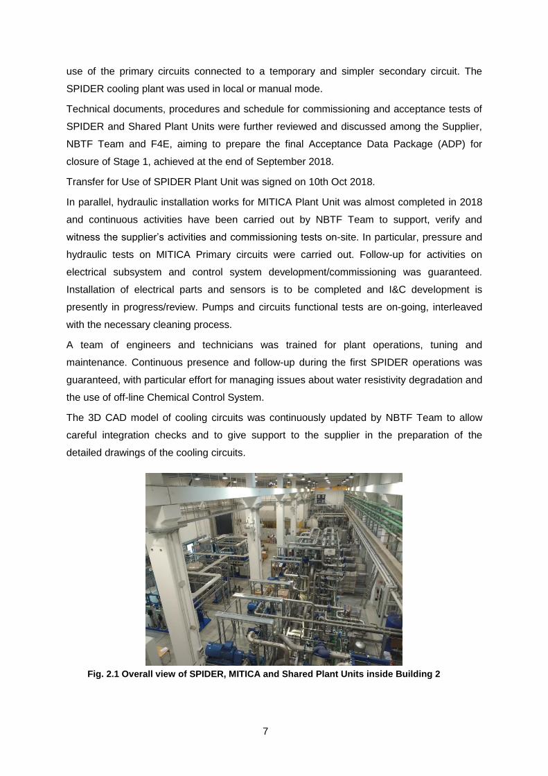
Fig. 2.1 Overall view of SPIDER, MITICA and Shared Plant Units inside Building 2

8
Overall views of pipes, pumps, heat exchangers and Chemical Control System inside
Building 2 are shown in Fig. 2.1. Pictures of pipes installed inside the MITICA Neutron Shield
at different levels are presented in Fig. 2.2.
2.1.1.3. Vacuum, gas injection and gas storage for SPIDER and MITICA
The SPIDER and Shared Plant Units were commissioned and tested in 2017. The Transfer
of Right to Use was signed and the plant was used for SPIDER operations in 2018. The final
Transfer for Use is planned in Q4 2018, after complete check of plant and submitted
documentation.
In parallel the review of the MITICA gas injection and vacuum system design progressed in
2018 and is presently on-going. Installation and SAT of the MITICA GVS Plant Unit are
planned to be completed in Q3-Q4 2019.
The following activities were carried out by engineers and technicians of NBTF Team as
technical follow-up support in 2018: participation to periodic technical meetings, controls and
solving of problems due to integration issues, review of documents submitted in F4E-IDM
(both for SPIDER and MITICA), preparation of maintenance contracts (with several
companies), continuous presence and follow-up during the SPIDER operational period.
2.1.1.4. Host activities
During 2018 significant amount of resources were invested on activities for construction
supervision and coordination, mainly concerning installation of experimental plants,
integration and conduction of SPIDER experiments. Particular effort was required to manage
interfaces between buildings and experimental plant units. Also the management of the
interfaces between plant units themselves required large effort: specifically to this end, the
interface management structure, run by NBTF Team, worked in a coordinate way with the
aim of reducing as much as possible clashes during installation of plants being able to define
in real-time the modifications required in any of the plants. A significant activity relevant to
integration management between different plants is represented by the component
interfacing the MITICA HV Transmission Line (JADA) and the HVD1-TL2 HV Bushing (F4E),
Fig. 2.2 Cooling pipes inside the MITICA Neutron Shield
Inlet/outlet cooling lines
for Beam Source
Inlet/outlet cooling lines for
Beam Line Components
Inlet and outlet cooling pipes at level -3 m

9
named Connecting Piece (CP). In origin this was a missing item and after a long negotiation
it was assigned to JADA. The development of an integrated mechanical model to calculate
the forces mutually transmitted between TL2 and HV Bushing in normal and seismic
conditions and the relevant analyses and verifications have been performed by NBTF Team.
On the basis of the obtained results the requirements for CP have been frozen and a special
mechanical structure to reinforce the system against seismic event has been designed,
provided and installed by NBTF Team.
The NBTF metrology team continued the site and components survey activities, where and
when necessary. Just as an example, metrology activities were fundamental during the
installation phase of the SPIDER Beam Source in the vacuum vessel and during the
installation of the MITICA HV Transmission Line.
The support to F4E and the other Domestic Agencies for the management of the
Construction-Erection All Risks insurance contract for the NBTF (CEAR), directly managed
by Consorzio RFX, continued. A flooding event in building #2, happened in November the
13th, was claimed to the insurance. Long negotiation was necessary due to difficulties in
finding agreement with the Cooling Plant supplier. At the end an agreement was found and
the recovery activity started with the support of a company expert on this type of activities.
The NBTF-site management, with reference to “Titolo IV of D.Lgs. 81/08” (Health and Safety
on-site), whose structure had been set up through the Implementation Agreement, continued
in 2018: the Responsible of Works and the Safety Coordinator continuously monitored and
periodically reported the state of the site. Significant resources were spent to assist F4E, in
particular by the Safety Coordinator who is in charge for issuing all the Plans for Safety and
Coordination (called PSC documents), being the latter an essential part for both the
procurement call for tenders and contracts management. RFX personnel (contract Liaison
Officer-LO and Deputy Liaison Officer-DLO) closely collaborated with the Safety Coordinator
to this end.
With the support of the Coordinator of the Directors of Works (namely CDL) the time
schedule for MITICA on-site activities was prepared and discussed among Consorzio RFX
and all involved Domestic Agencies during the year. During the July Programme Committee
the PM presented a proposal of modification of the schedule in order to reduce the impact on
some single procurement contracts in terms of duration and continuity of site works, to the
detriment of a partial modification of the purpose of JADA procurement. After internal
discussion among IO and DA’s the proposal was accepted and the new MITICA schedule
adopted. Furthermore, as a coordination method, more than 30 weekly Site Progress
Coordination Meetings (SPCMs) have been held, and the minutes distributed and uploaded

10
in F4E IDM. The SPIDER time schedule has been also managed by preparing, discussing
and verifying weekly the activity plan with a visibility of one week, 3 weeks and 3 months.
Several site inspections were performed by nearly all of the Companies and Domestic
Agencies that were operating.
General follow up activities were performed for all the companies working on-site and all the
companies working under “Balance of Plant” procurements. Further activities were devoted
to the follow-up of companies involved into the three signed Framework Contracts (CODAS-
Interlock-Safety, Diagnostics, Assembly).
Big effort has been given by the NBTF team to INDA and its suppliers concerning the
SPIDER AGPS system. In particular, support during completion of the installation,
commissioning and SAT, review of documentation in view of the transfer for use of the
system and management of the process to obtain the authorization of the use in the SPIDER
experiment.
As for the Licence to operate the two experiments:
- for SPIDER the authorization to use was obtained from the Local Authority
- for MITICA all the radioprotection technical reports have been completed and
submitted to the Italian Authorities
In 2018, the Transfer for Use to Consorzio RFX of some plants and components was
obtained. In October, the ownerships of SPIDER and of Cooling Plant SPIDER Plant Unit
have been transferred to IO and the responsibility for use to Consorzio RFX.
The management of safety and the organization of personnel works on roster for the
commissioning and experiment activities prosecuted during the whole year. In particular
NBTF Team guaranteed a continuous support in the management of the insulating SF6 Gas
in order to fill and empty HV components, also managing a contract of assistance with an
external company expert on this kind of activities.
Finally, NBTF Team managed and performed activities on SPIDER plant system in order to
guarantee the correct maintenance and intervention to solve troubleshooting and minor
faults.
SPIDER 2.1.2.
2.1.2.1. SPIDER Beam Source
The delivery of SPIDER Beam Source (BS) occurred in October 2017. Then the BS was
tested on-site and installed inside the Vacuum Vessel in February 2018. From April 2018 the
BS was used for SPIDER integrated commissioning and experiments, up to the end of 2018.
The Acceptance Data Package for the closure of SPIDER BS procurement contract was
11
delivered by the Supplier in Q2 2018, then reviewed by NBTF Team and F4E, and finally
approved in September 2018. The contract was then closed and the Final Transfer for Use
of SPIDER BS was signed on 10th October 2018.
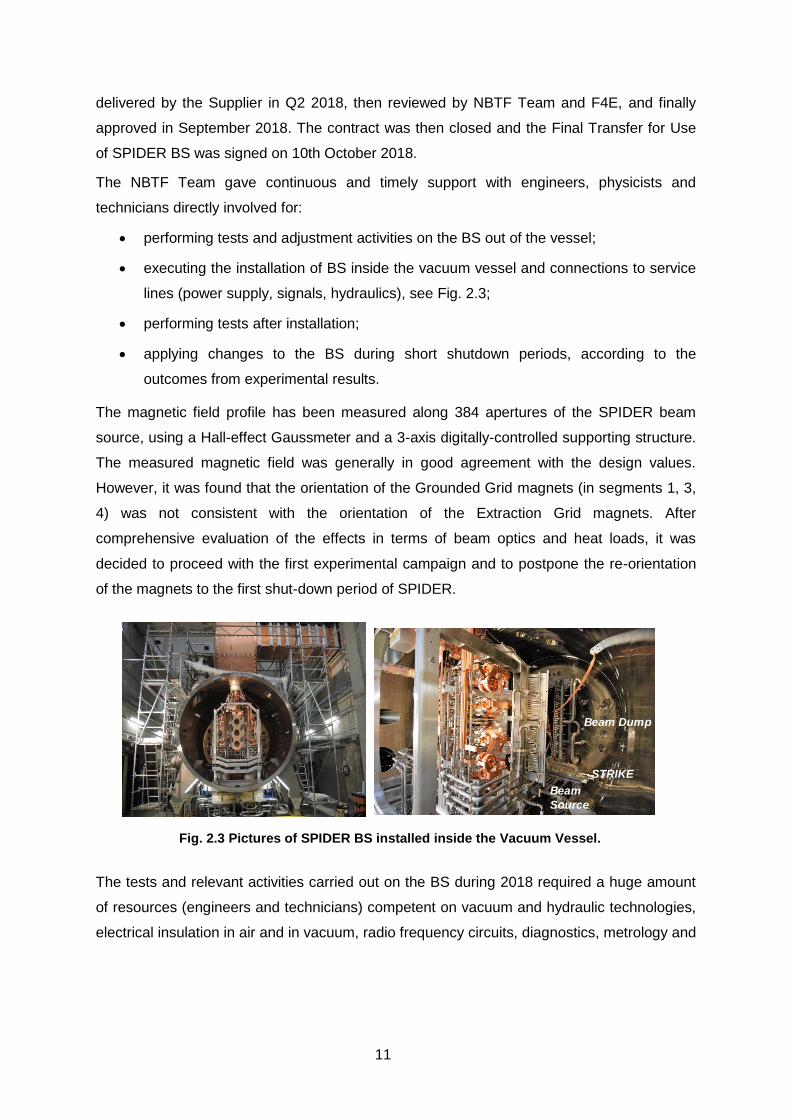
The NBTF Team gave continuous and timely support with engineers, physicists and
technicians directly involved for:
performing tests and adjustment activities on the BS out of the vessel;
executing the installation of BS inside the vacuum vessel and connections to service
lines (power supply, signals, hydraulics), see Fig. 2.3;
performing tests after installation;
applying changes to the BS during short shutdown periods, according to the
outcomes from experimental results.
The magnetic field profile has been measured along 384 apertures of the SPIDER beam
source, using a Hall-effect Gaussmeter and a 3-axis digitally-controlled supporting structure.
The measured magnetic field was generally in good agreement with the design values.
However, it was found that the orientation of the Grounded Grid magnets (in segments 1, 3,
4) was not consistent with the orientation of the Extraction Grid magnets. After
comprehensive evaluation of the effects in terms of beam optics and heat loads, it was
decided to proceed with the first experimental campaign and to postpone the re-orientation
of the magnets to the first shut-down period of SPIDER.
The tests and relevant activities carried out on the BS during 2018 required a huge amount
of resources (engineers and technicians) competent on vacuum and hydraulic technologies,
electrical insulation in air and in vacuum, radio frequency circuits, diagnostics, metrology and
Fig. 2.3 Pictures of SPIDER BS installed inside the Vacuum Vessel.
Beam
Source
STRIKE
Beam Dump
12
magnetic measurements 1. During the period of SPIDER operations a big effort was devoted
to investigate the issue of electrical discharges during pulses, both inside the BS and
towards the vacuum vessel. Accurate measurements, monitoring and studies were
performed investigating the effects of different RF parameters/configurations and of the
hydrogen pressure inside the vacuum vessel.
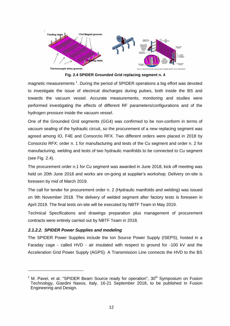
One of the Grounded Grid segments (GG4) was confirmed to be non-conform in terms of
vacuum sealing of the hydraulic circuit, so the procurement of a new replacing segment was
agreed among IO, F4E and Consorzio RFX. Two different orders were placed in 2018 by
Consorzio RFX: order n. 1 for manufacturing and tests of the Cu segment and order n. 2 for
manufacturing, welding and tests of two hydraulic manifolds to be connected to Cu segment
(see Fig. 2.4).
The procurement order n.1 for Cu segment was awarded in June 2018, kick off meeting was
held on 20th June 2018 and works are on-going at supplier’s workshop. Delivery on-site is
foreseen by mid of March 2019.
The call for tender for procurement order n. 2 (Hydraulic manifolds and welding) was issued
on 9th November 2018. The delivery of welded segment after factory tests is foreseen in
April 2019. The final tests on-site will be executed by NBTF Team in May 2019.
Technical Specifications and drawings preparation plus management of procurement
contracts were entirely carried out by NBTF Team in 2018.
2.1.2.2. SPIDER Power Supplies and modeling
The SPIDER Power Supplies include the Ion Source Power Supply (ISEPS), hosted in a
Faraday cage - called HVD - air insulated with respect to ground for -100 kV and the
Acceleration Grid Power Supply (AGPS). A Transmission Line connects the HVD to the BS
1 M. Pavei, et al. "SPIDER Beam Source ready for operation", 30th Symposium on Fusion Technology, Giardini Naxos, Italy, 16-21 September 2018, to be published in Fusion Engineering and Design.
Fig. 2.4 SPIDER Grounded Grid replacing segment n. 4

13
through the HV Bushing installed on the Vacuum Vessel (VV). A 3D view of the SPIDER
layout is shown in Fig. 2.5 .
AGPS has been procured by INDA, while all the other SPIDER PSs and auxiliary plants
necessary to operate SPIDER have been procured by F4E. As of 2018, the SPIDER Power
Supplies have been procured and commissioned.
Ion Source and Extraction Power Supply (ISEPS) system
Since 2017 the ISEPS is in operation. Following the installation of the BS, in 2018 ISEPS
has been extensively used in SPIDER experimental campaigns for the first time. A large
amount of activities has been performed to understand, troubleshoot and optimize ISEPS in
order to reach a reliable operation. In particular, the troubleshooting of the RF generators
and the characterization of the RF load in different operating conditions required a big effort.
In parallel, the activity on the modeling of the SPIDER power supplies progressed in
particular for the improvement and validation of the RF circuit models2, which took
advantage from the availability of the experimental data. The chaotic behaviour of coupled
RF circuits and oscillators has been reproduced, with results similar to those observed on
SPIDER, giving an important contribution to the understanding of the RF source behaviour.
Studies have started on the possibility to convert the oscillator to an amplifier (PP ultra-
linear), with minor hardware modifications (preamplifier power lower than 300W and
efficiency up to 65%). Some effort has been devoted to the general model of the breakdown
and to the effects on the RF circuits.
2 F. Gasparini, et al. "Investigation on stable operational regions for SPIDER RF oscillators", 30th Symposium on Fusion Technology, Giardini Naxos, Italy, 16-21 September 2018, to be published in Fusion Engineering and Design.
Fig. 2.5 3D view of SPIDER power supply system
14
Acceleration Grid Power Supply (AGPS) system
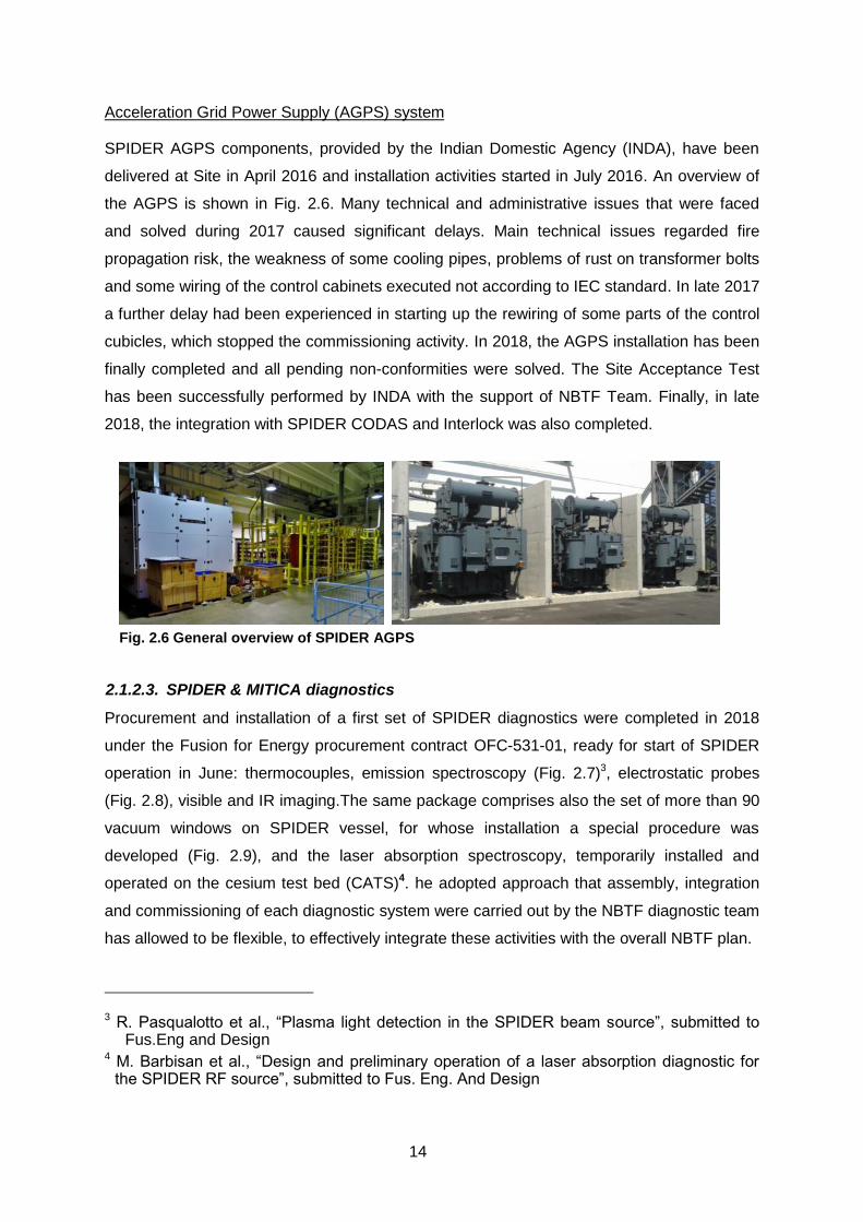
SPIDER AGPS components, provided by the Indian Domestic Agency (INDA), have been
delivered at Site in April 2016 and installation activities started in July 2016. An overview of
the AGPS is shown in Fig. 2.6. Many technical and administrative issues that were faced
and solved during 2017 caused significant delays. Main technical issues regarded fire
propagation risk, the weakness of some cooling pipes, problems of rust on transformer bolts
and some wiring of the control cabinets executed not according to IEC standard. In late 2017
a further delay had been experienced in starting up the rewiring of some parts of the control
cubicles, which stopped the commissioning activity. In 2018, the AGPS installation has been
finally completed and all pending non-conformities were solved. The Site Acceptance Test
has been successfully performed by INDA with the support of NBTF Team. Finally, in late
2018, the integration with SPIDER CODAS and Interlock was also completed.
2.1.2.3. SPIDER & MITICA diagnostics
Procurement and installation of a first set of SPIDER diagnostics were completed in 2018
under the Fusion for Energy procurement contract OFC-531-01, ready for start of SPIDER
operation in June: thermocouples, emission spectroscopy (Fig. 2.7)3, electrostatic probes
(Fig. 2.8), visible and IR imaging.The same package comprises also the set of more than 90
vacuum windows on SPIDER vessel, for whose installation a special procedure was
developed (Fig. 2.9), and the laser absorption spectroscopy, temporarily installed and
operated on the cesium test bed (CATS)4. he adopted approach that assembly, integration
and commissioning of each diagnostic system were carried out by the NBTF diagnostic team
has allowed to be flexible, to effectively integrate these activities with the overall NBTF plan.
3 R. Pasqualotto et al., “Plasma light detection in the SPIDER beam source”, submitted to Fus.Eng and Design
4 M. Barbisan et al., “Design and preliminary operation of a laser absorption diagnostic for the SPIDER RF source”, submitted to Fus. Eng. And Design
Fig. 2.6 General overview of SPIDER AGPS

15
The acceptance tests of these diagnostics were passed on 30th May, and then they have
been used for SPIDER operation; in particular spectroscopy and visible imaging, that
immediately provided valuable results, while thermocouples and electrostatic probes are still
being optimised against the induced RF noise.
For other diagnostics, R&D and partial procurement were carried out under F4E contracts
OFC-531-01 and OFC-531-02:
- STRIKE procurement progressed significantly with delivery in April of the CFC-1D
tiles, which successfully passed the acceptance tests; the remaining components are
now being procured, especially for the ex-vessel part, and their installation is being
prepared;5,6
5 M. Dalla Palma et al.,“Thermal analysis and high heat flux testing of unidirectional carbon–carbon composite for infrared imaging diagnostic”, Journal of Thermal Analysis and Calorimetry, 2018,
Fig. 2.7 Picture of the spectroscopy optical heads on SPIDER beam source (left) and
example of measured spectrum (right)
Fig. 2.8 Pictures of the custom 8 channels electronics module for the electrostatic probes on SPIDER beam source (left) and of the full electronics system in the two
dedicated cabinets (right)

16
- the neutron diagnostic progressed with procurement of the ex-vessel components,
beside repeating the removal and installation procedures of the in-vessel part; 7
- prototype custom cameras for beam tomography were completed and extensively
tested on the bench and on NIO1, also with a dual-camera configuration, and
procurement of the complete diagnostic started;
- procurement of Cavity Ring Down Spectroscopy (CRDS) started after acceptance of
the final specifications;
- drawings and specifications of the
electrostatic sensor prototypes for the beam
line components of MITICA were produced
(see Fig. 2.10) and will be manufactured in
house;
- specifications of fiber optic sensors to
perform thermo-mechanical measurements
on the beam line components of MITICA
6 A. Pimazzoni et al., “Thermal Characterization of the SPIDER Diagnostic Calorimeter” AIP Conference Proceedings
7 A. Muraro et al., “Directionality properties of the nGEM detector of the CNESM diagnostic system for SPIDER”, Nuclear Inst. and Methods in Physics Research, A (2018)
Fig. 2.9 Photo of a typical custom installation for the SPIDER vacuum
windows
Fig. 2.10 CAD models of electrostatic sensors prototypes for MITICA beam line components

17
were produced and procurement procedure started.
The OFC-531-01 contract was closed in October, as scheduled, after acceptance of the full
final documentation package.
The OFC-531-02 contract will be extended beyond 2019, to include custom radiation-hard
magnetic sensors for MITICA, as prototypes for the ITER HNB.
The collaboration with Milano Bicocca University and IFP-CNR contributed to develop the
neutron diagnostic, including a scintillator detector to measure the total neutron yield, and to
prepare the final design of the MITICA diagnostics8 under F4E-NBTF Work Programme
2018.
2.1.2.4. SPIDER CODAS, Central Interlock and Safety Systems
In 2018 the activity on the SPIDER CODAS,Central Interlock, and Central Safety Systems
was carried out under the task orders #02 and #03 of the F4E framework contract on the
NBTF control systems (F4E-OFC-280).
A set of completion activities were executed, aiming to
develop and produce the documentation of the interface with SPIDER/Shared cooling
and Gas and Vacuum System (GVS);
develop and debug the Central Interlock System;
implement the data acquisition systems of the SPIDER baseline diagnostics (source
thermocouples, emission spectroscopy, visible and infrared cameras, and
electrostatic probes);
produce the interface sheets and the manufacturing design for the data acquisition of
the SPIDER advanced diagnostics (STRIKE, neutrons monitor, tomography, cavity
ring-down spectroscopy).
The implementation of the SPIDER Central System was slowly progressed due to the
complexity of managing the system life cycle prescribed by the functional safety technical
standards, i.e. IEC 61508 for electrical/electronic/programmable electronic systems and IEC
61511 for industrial processes. The hardware architecture design was approved in Autumn
2018 9 and the Safety Instrumented Functions redefined. The system installation started in
8 M. Dalla Palma et al.,“Simulation of the beamline thermal measurements to derive particle beam parameters in the ITER neutral beam test facility”, Rev. Sci. Instrum. 89, 10J111 (2018)
9 S. Dal Bello, et al., Safety systems in the ITER neutral beam test facility, 30th Symposium of Fusion Technology, Giardini Naxos, Italy, Sept. 2018.

18
October 2018 and the Factory Acceptance Tests were executed in mid December.
Completion of installation and Site Acceptance Tests are planned for Q1/2019.
2.1.2.5. SPIDER integration and commissioning
The SPIDER integrated commissioning continued in 2018 with the optimization of the
operation of SPIDER CODAS, CIS, ISEPS and GVS, and with the integration of the SPIDER
Diagnostics10. The aim of the commissioning was to start as soon as possible the operation
of the SPIDER ion source, that was finally
achieved at the beginning of June 2018 with
the execution of the first SPIDER plasma
pulse11.
Several SPIDER diagnostics were tested
successfully with CODAS, namely the source
thermocouples, the diagnostic and inspection
imaging system, the emission spectroscopy,
and the electrostatic probes. An example of
data acquisition from the visible cameras is
given in Fig. 2.11.
The thermocouples required an ad-hoc campaign to optimize the signal quality that was
badly affected by a high-level noise, especially during the operation of the RF. Careful
earthing of I&C cubicles, proper connection of signal cable shields and insertion of filters on
cables were capable to cancel most of the signal noise injected in HVD.
Integration of SPIDER AGPS with CODAS and CIS was also prepared and the
commissioning campaign was carried out, starting from early December 2018.
2.1.2.6. SPIDER experiments: first results and issues
In mid-May 2018 SPIDER operation started.
First of all the following preparation activities were performed:
the gas injection system and the pumping system were characterised in order to
prepare the settings to control the pressure in the source during the pulses (when
operating with 8 cryogenic pumps a ratio of 4 is found between source and vessel
pressure);
10 A. Luchetta et al., SPIDER integrated commissioning, oral contribution presented at the 30th Symposium of Fusion Technology, Giardini Naxos, Italy, Sept. 2018.
11 G. Serianni, et al., SPIDER in the roadmap of the ITER Neutral Beams, invited talk presented at the 30th Symposium of Fusion Technology, Giardini Naxos, Italy, Sept. 2018.
Fig. 2.11 Real-time video streaming of
SPIDER visible cameras.
19
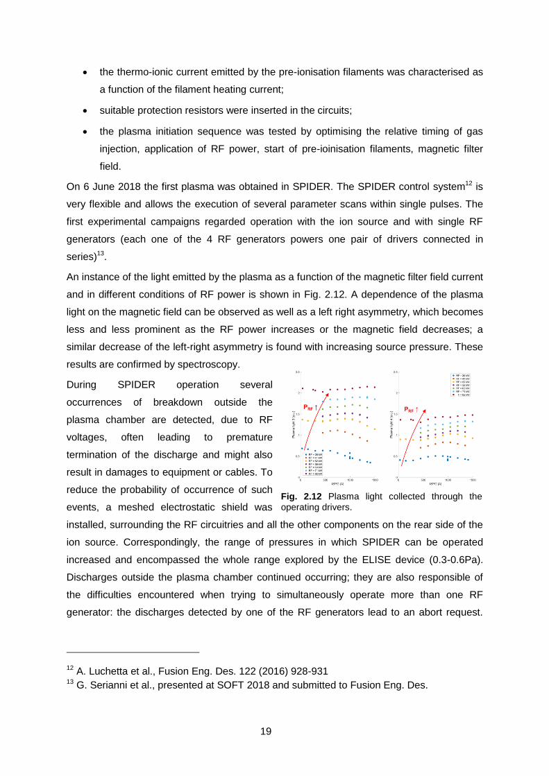
Fig. 2.12 Plasma light collected through the operating drivers.
the thermo-ionic current emitted by the pre-ionisation filaments was characterised as
a function of the filament heating current;
suitable protection resistors were inserted in the circuits;
the plasma initiation sequence was tested by optimising the relative timing of gas
injection, application of RF power, start of pre-ioinisation filaments, magnetic filter
field.
On 6 June 2018 the first plasma was obtained in SPIDER. The SPIDER control system12 is
very flexible and allows the execution of several parameter scans within single pulses. The
first experimental campaigns regarded operation with the ion source and with single RF
generators (each one of the 4 RF generators powers one pair of drivers connected in
series)13.
An instance of the light emitted by the plasma as a function of the magnetic filter field current
and in different conditions of RF power is shown in Fig. 2.12. A dependence of the plasma
light on the magnetic field can be observed as well as a left right asymmetry, which becomes
less and less prominent as the RF power increases or the magnetic field decreases; a
similar decrease of the left-right asymmetry is found with increasing source pressure. These
results are confirmed by spectroscopy.
During SPIDER operation several
occurrences of breakdown outside the
plasma chamber are detected, due to RF
voltages, often leading to premature
termination of the discharge and might also
result in damages to equipment or cables. To
reduce the probability of occurrence of such
events, a meshed electrostatic shield was
installed, surrounding the RF circuitries and all the other components on the rear side of the
ion source. Correspondingly, the range of pressures in which SPIDER can be operated
increased and encompassed the whole range explored by the ELISE device (0.3-0.6Pa).
Discharges outside the plasma chamber continued occurring; they are also responsible of
the difficulties encountered when trying to simultaneously operate more than one RF
generator: the discharges detected by one of the RF generators lead to an abort request.
12 A. Luchetta et al., Fusion Eng. Des. 122 (2016) 928-931 13 G. Serianni et al., presented at SOFT 2018 and submitted to Fusion Eng. Des.

20
This was confirmed by masking the apertures of the extraction grid thanks to a stainless
steel plate slid on the upstream surface of the grid.
The reduction of the overall conductance, corresponding to a ratio of 20 between source and
vessel pressure, allowed to investigate normal source pressure conditions with very low level
of vessel pressure: indeed all RF generators worked simultaneously. These experiments
gave also preliminary indications about the modifications to be implemented in the pumping
speed. The operational space explored during SPIDER operation is shown in Fig. 2.13; in
the “blocked” case the higher RF power is obtained thanks to the use of more than one RF
generator.
Without the extraction grid mask, a first assessment of DC voltage holding of the SPIDER
source was possible by the extraction grid power supply. No breakdowns were detected
when applying 12kV between source and vacuum vessel for several tens of seconds up to
0.18 Pa in the vacuum vessel.
MITICA 2.1.3.
2.1.3.1. Vacuum Vessel
The MITICA Vacuum Vessel (VV) is composed by three main parts: the VV support
structure, the Beam Source Vessel (BSV) (containing the Beam Source and connected to
the PS Transmission Line) and the Beam Line Vessel (BLV) (containing the Beam Line
Components). The procurement contract is on-going since January 2015 and the Supplier is
De Pretto Industrie (I).
The MITICA VV support structure and the Rear Lid Handling System were already
manufactured, installed and tested on-site in 2017 (see Fig. 2.14).
The BSV and BLV manufacturing proceeded in 2018 with an effective support given by
NBTF Team for technical follow-up. In particular the welding recovery activities on both BSV
Fig. 2.13 Explored operational space for SPIDER; in the “blocked” case the source pressure is 20 times the vessel pressure; in the other cases the ratio is 4.

21
and BLV were successfully completed,
with a huge effort for control of
deformations during the execution of
critical welding activities.
After welding recovery, the BSV final
machining and dimensional controls were
completed in Q4 2018 (see Fig. 2.15).
Further grinding of weld beads are on-
going and will be followed by the accurate
cleaning and dry-ice blasting of the
internal surfaces, to be carefully prepared
for HV holding reasons.
The tight schedule for BSV foresees the vacuum leak tests in Jan-Feb 2019, the delivery by
March and the completion of final installation and tests by mid May 2019.
As regards the BLV, welding recovery and sand blasting were completed in October 2018.
Dimensional controls after weld recovery were positively completed and final machining
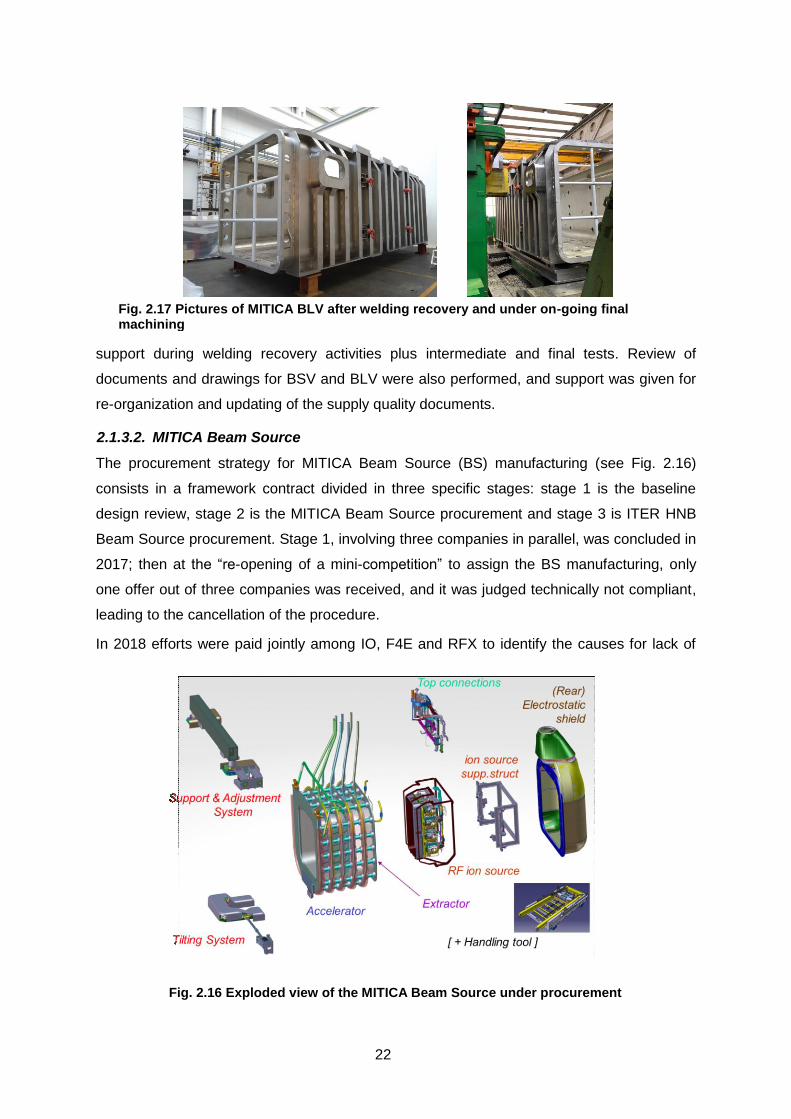
started mid November 2018 ((see Fig. 2.17). BLV delivery on-site is presently expected in
September 2019 and completion of tests on-site by mid November 2019.
All these activities and relevant milestones are carefully controlled and verified in order to get
an armonized and integrated schedule for MITICA injector installation, considering the
parallel on-going activities at PRIMA site for integration and tests of auxiliaries and power
supplies.
The NBTF Team guaranteed the technical follow-up during 2018. Frequent meetings and
inspections at Supplier’s premises (weekly) were necessary for continuous verifications and
Fig. 2.14 The MITICA VV support structure installed and tested on-site, inside the MITICA
Neutron Shield
Fig. 2.15 The MITICA BSV under machining and ready for dimensional controls.
22
support during welding recovery activities plus intermediate and final tests. Review of
documents and drawings for BSV and BLV were also performed, and support was given for
re-organization and updating of the supply quality documents.
2.1.3.2. MITICA Beam Source
The procurement strategy for MITICA Beam Source (BS) manufacturing (see Fig. 2.16)
consists in a framework contract divided in three specific stages: stage 1 is the baseline
design review, stage 2 is the MITICA Beam Source procurement and stage 3 is ITER HNB
Beam Source procurement. Stage 1, involving three companies in parallel, was concluded in
2017; then at the “re-opening of a mini-competition” to assign the BS manufacturing, only
one offer out of three companies was received, and it was judged technically not compliant,
leading to the cancellation of the procedure.
In 2018 efforts were paid jointly among IO, F4E and RFX to identify the causes for lack of
Fig. 2.17 Pictures of MITICA BLV after welding recovery and under on-going final machining
Fig. 2.16 Exploded view of the MITICA Beam Source under procurement

23
offers from bidders and the best way forward: technical and contractual specifications were
revised to take into account risks and difficulties perceived on the bidders’ side that impacted
the result. The tender was re-issued in June 2018 and three compliant offers were received
in August 2018. A thorough evaluation was carried out with the technical contribution by
RFX, leading to signature of the contract with Alsyom-Seiv in October and the KoM in
November 2018. NBTF Team provided feedback and technical support for checks and
review of technical/quality documents and for tenders evaluation.
Discussion over early documentation and preliminary phases has already begun after KoM.
2.1.3.3. MITICA Beam Line Components
A two stages contract was launched: Stage 1 for baseline review, Stage 2 for MITICA BLCs
procurement. Three suppliers were awarded for Stage 1: AVS Tecnalia (E), SIMIC (I), De
Pretto Industrie – ATT Angelantoni Consortium (I)
Stage 1 Kick-off meetings (one for each supplier) were held in December 2017 and the
activities were performed by the three competitors in parallel and carefully followed up by
NBTF Team. Stage 1 closure occurred in Q4 2018. Issue of Call for tender, tender
evaluation and awarding of stage 2 are planned in Q2-Q3 2019.
Technical support for the follow-up of Stage 1 was guaranteed by NBTF Team with weekly
and monthly meetings with three competitors. Substantial amount of resources were
involved for review of several documents and follow-up of prototypes manufacturing/testing
by three competitors in parallel. Welding processes, machining and assembly sequences,
tolerances and metrology for dimensional controls, vacuum compatibility requirements and
intermediate and final tests were deeply discussed and optimized together with the three
suppliers during stage 1. Pictures of prototypes manufactured during stage 1 are shown in
Fig. 2.18.
2.1.3.4. Cryopumps
Two large Cryopumps will be installed inside the MITICA Beam Line Vessel (BLV) to
Fig. 2.18 Pictures of MITICA BLCs prototypes for ERID and Calorimeter, manufactured and
tested during 2018
Calorimeter swirl tube elements

24
guarantee proper vacuum conditions inside the vessel during MITICA operation (see Fig.
2.19). The Cryopumps are based on adsorption pumping by charcoal coated cryopanels
(CPs), 8 m long, 2.8 m high and 0.45 m deep, operated between 4.5 K and 400 K. These
cryopanels are surrounded by a Thermal Radiation Shield (TRS) operated between 80 K
and 400 K. The CPs will be at the lower temperatures during normal operations, while 100 K
or 400 K will be achieved during periodic pump regenerations necessary to remove from the
CPs the adsorbed gas (H2 or D2). The pumping speed estimated for the two pumps
operating in parallel are 5000 m3/s for H2 and 3800 m3/s for D2.
The complex procurement of Cryopumps is subdivided in three lots, corresponding to
specific kowledge and expertise of different suppliers: Lot 1 for support frame and assembly,
Lot 2 for expansion profiles and Lot 3 for charcoal coating of pumping surfaces.
The contract for procurement was awarded in Q1 2018: SDMS (F) for Lot 1 and 3, Ravanat
(F) for Lot 2. The kick off meeting was held on 15th – 16th May 2018 and the procurement
activities are on-going.
During 2018 technical follow-up was carried out by NBTF Team for tender evaluation,
awarding of the contract and support during first procurement phases. Participation to bi-
weekly and monthly meetings and review of technical documents were guaranteed. In
Fig. 2.19 CAD views of MITICA Cryopumps

25
particular material purchase and specific manufacturing processes and prototypes for
qualification were thoroughly discussed. First tests for qualification of Aluminium surface
emissivity were directly managed by Consorzio RFX.
Further activities in 2018 were addressed to the design of the Cryopump Assembly Tool that
will be necessary for the installation of Cryopumps inside the MITICA VV.
The development of a detailed assembly sequence and the Assembly Tool design were
carried out (see Fig. 2.20) and Technical Specification for procurement are under
preparation. These activities have been managed by NBTF Team and carried out by CCFE
as third part under the Work Programme WP2018.
2.1.3.5. Cryogenic Plant
The MITICA Cryogenic Plant is designed to produce supercritical Helium (ScHe) at 4.6K and
gaseous Helium (GHe) at 81K and to feed these cryogenic fluids respectively to the
cryopanel (CP) and to the thermal radiation shield (TRS) assemblies of the cryopumps. The
expected heat loads to be removed in pulse-on scenario are 800 W on CP and 17.4 kW on
TRS assembly. The same plant shall also manage the regeneration of Cryopumps at
different temperatures.
The procurement contract for MITICA Cryogenic Plant was launched in September 2016 and
the supplier is ALAT (Air Liquide Advanced Technologies) (F).
The main equipment, components, warm lines and cryo lines have been delivered.
The installation activities, started in Q2 2018, are still on-going and are planned to be
completed by the end of 2018. Almost all of equipment and warm/cryogenic lines have been
installed inside Building #2 and Building #4 (see Fig. 2.21) and on the roof of Building #4.
The installation of cryogenic lines inside MITICA Neutron Shield is on-going and completion
is foreseen within January 2019.
Fig. 2.20 CAD views and results of structural analyses for MITICA Cryopump Assembly Tool

26
The electrical part of the plant is still waiting for tests at the factory and approval of
certificates before release for delivery and start of installation. In the meanwhile installation
of cable-trays is foreseen within January 2019. Completion of assembly, commissioning and
Site Acceptance Tests is expected within Q3 2019.
The NBTF Team guaranteed the technical follow-up during 2018. Frequent meetings were
necessary for continuous verifications and support during on-site installation activities.
Reviews of several documents submitted by the Supplier were also performed. Most of the
issues so far identified and solved regarded clashes with other plants, problems at interfaces
and details/verifications for fixing of equipment, pipes and cable trays to PRIMA Buildings
floors and walls. The effort for this follow up was much more then foreseen due to lack of
preliminary assessment and installation studies on-site by the supplier and sub-supplier in
charge for installation.
The procurements of further parts to be integrated with the Cryogenic Plant were also in
charge of NBTF Team in 2018: the cooling unit for He compressors and the liquid Nitrogen
tanks to be installed out of PRIMA buildings.
Training of NBTF Team engineers and technicians is a major task foreseen in 2019 during
commissioning and site acceptance tests. This is necessary to get the proper knowledge
and capability for operating and maintaining the MITICA Cryogenic Plant.
2.1.3.6. MITICA Conversion system (AGPS-CS, ISEPS, GRPS)
The MITICA Conversion system includes all the power supplies necessary for the operation
of the MITICA experiment, excluding the components for the generation of the High Voltage,
i.e. the AGPS Conversion System (AGPS-CS), the Ion Source and Extraction Power
Supplies (ISEPS) and the Ground Related Power Supplies (GRPS). Substantial progress in
Auxiliary
Cold Box Main
Cold Box
Fig. 2.21 Pictures of MITICA Cryogenic Plant components and piping inside Building 2.
27
the installation and commissioning of these power supplies has been made. NBTF Team
supported all the involved companies during the design, factory tests and activities at Site.
In the following, the progress achieved in 2018 for each subsystem is described.
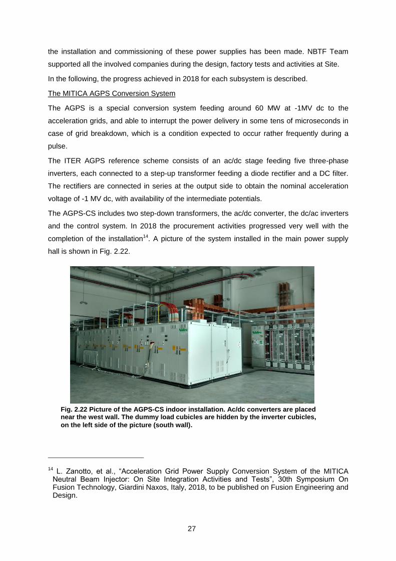
The MITICA AGPS Conversion System
The AGPS is a special conversion system feeding around 60 MW at -1MV dc to the
acceleration grids, and able to interrupt the power delivery in some tens of microseconds in
case of grid breakdown, which is a condition expected to occur rather frequently during a
pulse.
The ITER AGPS reference scheme consists of an ac/dc stage feeding five three-phase
inverters, each connected to a step-up transformer feeding a diode rectifier and a DC filter.
The rectifiers are connected in series at the output side to obtain the nominal acceleration
voltage of -1 MV dc, with availability of the intermediate potentials.
The AGPS-CS includes two step-down transformers, the ac/dc converter, the dc/ac inverters
and the control system. In 2018 the procurement activities progressed very well with the
completion of the installation14. A picture of the system installed in the main power supply
hall is shown in Fig. 2.22.
14 L. Zanotto, et al., “Acceleration Grid Power Supply Conversion System of the MITICA Neutral Beam Injector: On Site Integration Activities and Tests”, 30th Symposium On Fusion Technology, Giardini Naxos, Italy, 2018, to be published on Fusion Engineering and Design.
Fig. 2.22 Picture of the AGPS-CS indoor installation. Ac/dc converters are placed near the west wall. The dummy load cubicles are hidden by the inverter cubicles,
on the left side of the picture (south wall).

28
After the installation, the commissioning on the dummy load started around March 2018, and
was successfully completed during summer. Each AGPS-CS stage has been tested up to
the nominal current and voltage. The breakdown sequence has been proved to be effective.
Fig. 2.23 shows a picture taken during the Site Acceptance Tests. The AGPS-CS system is
now ready to be integrated with the rest of the MITICA Power Supply system.
The MITICA ISEPS
The ISEPS design adaptation to MITICA were completed in 2017. In 2018, the follow-up of
the contract continued as described hereinafter. The first part of the year was devoted to
discuss and prepare the installation activity foreseen for late 2018 and to integrate this
activity within the constraints of the overall MITICA schedule. In summer, the installation of
the fibre optics from HVD1 (where ISEPS must be installed) to the MITICA local control room
were laid down and checked. The review of the documentation was completed and
manufacture released for medium voltage and low voltage distribution boards. NBTF Team
then attended to FAT in Himmelwerk, IME and OCEM, where all various components and
subsystems of ISEPS underwent the contractual factory tests. In late 2018, the ISEPS
equipment has been positioned inside HVD1 after the dismantling of one wall of the deck, in
view of the bulk of the installation activity foreseen in 2019.
The MITICA GRPS
The MITICA GRPS is actually composed by the Residual Ion Dump (RID) power supply
only. This power supply has to provide an average voltage up to 25 kV, plus an ac low-
frequency voltage component with maximum amplitude of 5 kV, to spread the power
Fig. 2.23 Picture of the AGPS-CS Site Acceptance Tests. NIDEC’s engineer explaining to F4E, ITER, JADA and Consorzio RFX representatives the result of
the tests.
29
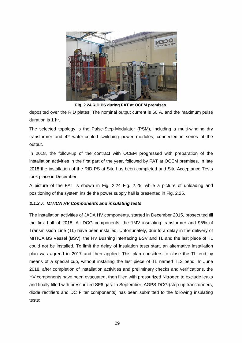
deposited over the RID plates. The nominal output current is 60 A, and the maximum pulse
duration is 1 hr.
The selected topology is the Pulse-Step-Modulator (PSM), including a multi-winding dry
transformer and 42 water-cooled switching power modules, connected in series at the
output.
In 2018, the follow-up of the contract with OCEM progressed with preparation of the
installation activities in the first part of the year, followed by FAT at OCEM premises. In late
2018 the installation of the RID PS at Site has been completed and Site Acceptance Tests
took place in December.
A picture of the FAT is shown in Fig. 2.24 Fig. 2.25, while a picture of unloading and
positioning of the system inside the power supply hall is presented in Fig. 2.25.
2.1.3.7. MITICA HV Components and insulating tests
The installation activities of JADA HV components, started in December 2015, prosecuted till
the first half of 2018. All DCG components, the 1MV insulating transformer and 95% of
Transmission Line (TL) have been installed. Unfortunately, due to a delay in the delivery of
MITICA BS Vessel (BSV), the HV Bushing interfacing BSV and TL and the last piece of TL
could not be installed. To limit the delay of insulation tests start, an alternative installation
plan was agreed in 2017 and then applied. This plan considers to close the TL end by
means of a special cup, without installing the last piece of TL named TL3 bend. In June
2018, after completion of installation activities and preliminary checks and verifications, the
HV components have been evacuated, then filled with pressurized Nitrogen to exclude leaks
and finally filled with pressurized SF6 gas. In September, AGPS-DCG (step-up transformers,
diode rectifiers and DC Filter components) has been submitted to the following insulating
tests:
Fig. 2.24 RID PS during FAT at OCEM premises.

30
1.2 MV dc for 1 hour
1.06 MV dc for 5 hours, followed by five fast ramps up to 1.26 MV
Tests were successfully passed, see Fig. 2.26, allowing to prosecute the setting up of the
plant for the next HV tests.
In November, the second set of HV tests have been performed in order to test the TLs. Also
in this case the test was successfully passed allowing to maintain the MITICA schedule
without significant delays.
In the last part of the year, after removal of the SF6 gas, the NBTF Team followed the works
for installation of the seismic reinforcement and for preparation of the plant for next
Fig. 2.25 RID PS installation.
1st Step 1200kV - 1 HOUR 2
nd Step 1060kV - 5 HOURS
Fig. 2.26 AGPS-DCG insulating tests.

31
installation of the Connecting Piece. Also in 2018, strong support has been given by NBTF
Team to the installation and test of JADA components. The activities were performed under
the supervision of QST laboratory of Naka and Hitachi experts, with specific contributions of
Consorzio RFX to finalize solutions for different issues encountered during daily operations,
with the assistance of a European company (Synecom) for the management of the SF6 gas
and assistance during HV tests.
2.1.3.8. MITICA I&C
The design of MITICA CODAS, Central Interlock and Safety Systems progressed with the
definition of the interfaces with MITICA GVS, Cooling Plant, Cryogenic Plant, ISEPS, AGPS,
and GRPS. miniCODAS was adapted for usage in the AGPS and GRPS factory acceptance
tests. The ITER high-performace networks were studied to understand their usability in
MITICA CODAS. The Time Communication Network technology was prototyped and the
software drivers were prepared and tested15. The data archiving network was also tested,
but it was considered an immature technology for application in MITICA. The Synchronous
databus Network was also tested and eventually considered as a viable and reliable
technology for MITICA.
Progress was also achieved in the definition of the MITICA CODAS and Central Interlock
system, identifying the ITER-relevant and NBTF-only components.16
ITER Neutral Beam Injector Physics 2.1.4.
MITICA beamlet optics and magnetic deflection compensation experiments
The analysis of the overall results of the 1st and 2nd Joint Experiment campaigns (carried
out on the NITS device at QST Naka, Japan in Feb-Mar 2016 and in Dec 2017) has been
completed using a new, more precise procedure for fitting the beamlet thermal images on
the CFC target. A comprehensive database correlating the beam thermal footprint and the
beamlet optics to the operating conditions of NITS and to the transverse magnetic field at the
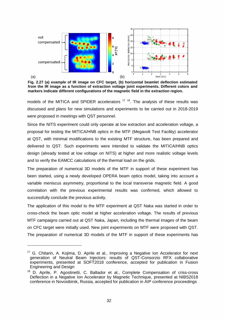
meniscus has been obtained, including all the data collected on NITS experiments (see Fig.
2.27).
The final part of these activities allowed to gain a better understanding on the effect of
transverse magnetic field on meniscus shape and therefore an improvement of the 3D optics
15 G. Manduchi, et al., The timing system of the ITER full-size neutral beam injector prototype, 30th Symposium of Fusion Technology, Giardini Naxos, Italy, Sept. 2018
16 N. Pomaro, et al., Design of MITICA control and interlock systems, 30th Symposium of Fusion Technology, Giardini Naxos, Italy, Sept. 2018.
32
models of the MITICA and SPIDER accelerators 17 18. The analysis of these results was
discussed and plans for new simulations and experiments to be carried out in 2018-2019
were proposed in meetings with QST personnel.
Since the NITS experiment could only operate at low extraction and acceleration voltage, a
proposal for testing the MITICA/HNB optics in the MTF (Megavolt Test Facility) accelerator
at QST, with minimal modifications to the existing MTF structure, has been prepared and
delivered to QST. Such experiments were intended to validate the MITICA/HNB optics
design (already tested at low voltage on NITS) at higher and more realistic voltage levels
and to verify the EAMCC calculations of the thermal load on the grids.
The preparation of numerical 3D models of the MTF in support of these experiment has
been started, using a newly developed OPERA beam optics model, taking into account a
variable meniscus asymmetry, proportional to the local transverse magnetic field. A good
correlation with the previous experimental results was confirmed, which allowed to
successfully conclude the previous activity.
The application of this model to the MTF experiment at QST Naka was started in order to
cross-check the beam optic model at higher acceleration voltage. The results of previous
MTF campaigns carried out at QST Naka, Japan, including the thermal images of the beam
on CFC target were initially used. New joint experiments on MTF were proposed with QST.
The preparation of numerical 3D models of the MTF in support of these experiments has
17 G. Chitarin, A. Kojima, D. Aprile et al., Improving a Negative Ion Accelerator for next generation of Neutral Beam Injectors: results of QST-Consorzio RFX collaborative experiments, presented at SOFT2018 conference, accepted for publication in Fusion Engineering and Design
18 D. Aprile, P. Agostinetti, C. Baltador et al., Complete Compensation of criss-cross Deflection in a Negative Ion Accelerator by Magnetic Technique, presented at NIBS2018 conference in Novosibirsk, Russia, accepted for publication in AIP conference proceedings
(a) (b)
Fig. 2.27 (a) example of IR image on CFC target, (b) horizontal beamlet deflection estimated from the IR image as a function of extraction voltage joint experiments. Different colors and
markers indicate different configurations of the magnetic field in the extraction region.
33
been started, using both OPERA and COMSOL simulations. Such experiments will also
allow to verify the EAMCC calculations of the thermal load on the grids for MITICA/HNB.
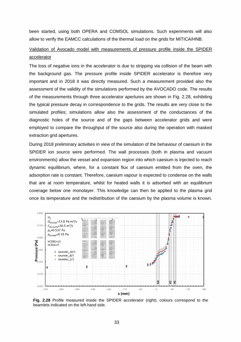
Validation of Avocado model with measurements of pressure profile inside the SPIDER
accelerator
The loss of negative ions in the accelerator is due to stripping via collision of the beam with
the background gas. The pressure profile inside SPIDER accelerator is therefore very
important and in 2018 it was directly measured. Such a measurement provided also the
assessment of the validity of the simulations performed by the AVOCADO code. The results
of the measurements through three accelerator apertures are shown in Fig. 2.28, exhibiting
the typical pressure decay in correspondence to the grids. The results are very close to the
simulated profiles; simulations allow also the assessment of the conductances of the
diagnostic holes of the source and of the gaps between accelerator grids and were
employed to compare the throughput of the source also during the operation with masked
extraction grid apertures.
During 2018 preliminary activities in view of the simulation of the behaviour of caesium in the
SPIDER ion source were performed. The wall processes (both in plasma and vacuum
environments) allow the vessel and expansion region into which caesium is injected to reach
dynamic equilibrium, where, for a constant flux of caesium emitted from the oven, the
adsorption rate is constant. Therefore, caesium vapour is expected to condense on the walls
that are at room temperature, whilst for heated walls it is adsorbed with an equilibrium
coverage below one monolayer. This knowledge can then be applied to the plasma grid
once its temperature and the redistribution of the caesium by the plasma volume is known.
Fig. 2.28 Profile measured inside the SPIDER accelerator (right); colours correspond to the beamlets indicated on the left-hand side.

34
In the plasma phase, caesium released from the walls by evaporation can be recycled back
to the same wall due to the presence of the plasma sheath.
Vacuum high voltage holding modeling and experiments 2.1.5.
2.1.5.1. HVPTF experiments
An experimental study on the relation between the conditioning process of the surface of the
electrodes and the topology of the electric field has been carried out. Using a dual power
supply and two electrodes inside a grounded vacuum vessel, one electrode at positive
potential and another at negative potential, the electrodes were fully conditioned under a
perfectly symmetric electric field configuration. When the voltage of the negative electrode to
ground was decreased by few kV, thus creating a lower electric field with slightly different
(asymmetric) electric field topology, the occurrence of micro-discharges was regularly
observed. These experiments confirmed that small variations of the surface conditions on
"facing spots" on the two electrodes are sufficient to trigger a discharge. In order to analyze
this phenomenon, a series of numerical analyses has also been carried out considering a
mutual exchange of charged particles between electrodes.
An experimental campaign using meshed “transparent" anode (i.e. anode covered by a thin
metallic mesh) has also been carried out at HVPTF: a sphere-plane configuration (gap
length 37.5 mm) was assumed as reference case to discriminate if the thin metallic mesh
can improve voltage holding in high vacuum (see Fig. 2.29).
An Infra-Red camera was also used for monitoring the electrode temperatures during the
test. During the campaign, the high voltage conditioning was carried out using an automatic
procedure. No voltage holding improvement was observed with respect to the reference
configuration constituted by a solid anode. The thermal measurements indicated that the
temperature variation of the electrode surface was negligible.
However, a considerable temperature increase was detected on the metallic support
sustaining the anode. A specific study allowed to understand the physical phenomenon
causing the power dissipation, probably related to an electron cascade regenerative
Fig. 2.29 Meshed (transparent) anode and temperature increase on metallic electrode support

35
phenomena 19.
A first experimental campaign was carried out using a spherical stainless steel cathode with
plasma-sprayed alumina coating ("lollipop electrode") and a plane electrode (see Fig. 2.30).
The high voltage conditioning was carried out using the automatic procedure. This electrode
setup demonstrated a voltage holding up to 440 kVdc. On the other hand, a maximum
voltage holding of 430 kV for the same sphere-plane configuration without alumina coating
was found. The conditioning required 300-400 breakdowns in both configurations. No
substantial improvement of voltage holding has been observed using the alumina coating.
After the tests, the alumina coating appeared to be cracked and locally damaged in several
locations.
A cross-check of the experimental results has been carried out in order to rule out the effect
of small dust and contaminants which were accumulating inside the vacuum chamber, in
particular on the surfaces of the support of the negative electrodes.
After thorough cleaning of the vacuum chamber and electrodes, the tests with sphere-plane
configuration were repeated. Although the conditioning procedure took a considerably
shorter time, in the end the voltage holding capability was similar to the one observed in the
previous session.
Additional tests on the 40 mm sphere-plane configuration with gap length of 72 mm were
carried out in high vacuum. After more than 140 hours of conditioning and almost 300
breakdowns, a "saturation" breakdown voltage at 580 kV was reached, confirming that the
maximum voltage achieved during the previous tests (with gap lengths lower than 72 mm)
depended on the electrode configuration under test rather than on the interaction with the
vacuum vessel wall; a similar result has been also obtained with a gap length of 148 mm.
19 N.Pilan, S. De Ambrosis, A. De Lorenzi et al, Evidences of accumulation points in cascade regenerative phenomena observed in high voltage dc devices insulated by vacuum, https://doi.org/10.1088/2399-6528/aaea95
Fig. 2.30 Spherical cathode with plasma-sprayed alumina coating

36
This result confirms the existence, for a single gap in high vacuum, of an upper limit in the
hold-off voltage of about 600 kV for vacuum gap length of tens of centimetres.
The beneficial “pressure effect” was also verified experimentally with Argon in sphere-plane
configuration with gap length of 30, 72 and 148 mm. When low pressure gas was injected
(about 5 10-2 Pa) a higher breakdown voltage between electrodes (up to 775 kV for 72 mm
gap and up to 800 kV for 148 mm gap) was achieved and a stable hold-off voltage of 780 kV
has been kept for more than 10 minutes without breakdowns. The left branch of the Paschen
curve in Argon has been also partially investigated.
The High Voltage Short Gap Test Facility (HVSGTF) to measure the Fowler Nordheim
emission current has been assembled at Consorzio RFX. The first HV tests in vacuum have
been carried out to the maximum voltage (100 kVdc) to verify the X ray biological screen. A
further activity aimed to implement a pico ammeter to measure the dark currents has been
started.
2.1.5.2. Vacuum High Voltage modelling and preparation of MITICA HV holding tests
The probabilistic model previously developed at Consorzio RFX for the prediction of HV
holding in vacuum has been further developed, including the capability to determine the
breakdown probability along all possible discharge trajectories between electrodes. The
model was validated also on the basis of the experimental results obtained during the tests
of the High Voltage Bushing for MITICA 20. The experimental results obtained at QST on the
reduced-size 500 kV voltage holding experiment in vacuum were also used to refine the
model. The model has been applied to the design and preparation of first HV holding tests at
1 MV in the MITICA vessel (see Fig. 2.31).
The main objectives of these tests are the following:
Experimental determination of the HV holding capability in high vacuum in MITICA
vessel under realistic conditions with large electrodes (some m2) and long gaps (up
to 0.6 -1.0 m);
Evaluation of the HV holding improvement achievable by a small increase of the gas
pressure (the so called "pressure effect", which typically takes place below 50 mPa);
Experimental determination of the HV holding capability in presence of an
intermediate electrostatic screen at 600 kV, optimization of the shape and
20 N. Pilan ; A. Kojima ; R. Nishikiori et al, Numerical–Experimental Benchmarking of a Probabilistic Code for Prediction of Voltage Holding in High Vacuum, IEEE Transactions on Plasma Science, 2018, 46, 5, https://doi.org/10.1109/TPS.2017.2775246

37
number/size of holes in the electrostatic screen, also with regard to the resulting gas
pressure distribution;
Characterization of the behaviour of the HV power supplies and transmission line in
case of breakdown;
Measurement of the currents under realistic conditions during the execution of the
tests as well as of the current and the EM noise in case of breakdown.
The test configuration considered for these tests includes a mock-up of the Beam Source
(sphere + cylinder), with and without an intermediate electrostatic screen. The intermediate
electrostatic screen will be provided with holes for allowing the gas flow. In order to start the
tests at low voltage, the distance between the mock-up of the Beam source (sphere) and the
ground electrode (plane) shall be adjustable (see Fig. 2.32). Using the above mentioned
numerical models, the optimization of the shape of the mock-up and of the screen has been
(a) (b)
Fig. 2.32 CAD view (a) and layout (b) of the Beam Source mock-up with the movable electrode
inside the MITICA vessel, as proposed for the first 1MV voltage holding tests
(a) (b) (c)
Fig. 2.31 (a): geometry of the MITICA Beam Source and intermediate electrostatic shield in the vessel; (b) and (c): configuration considered for the first 1 MV tests in the MITICA vessel,
including a beam source mock-up and an intermediate electrostatic shield mock-up with holes
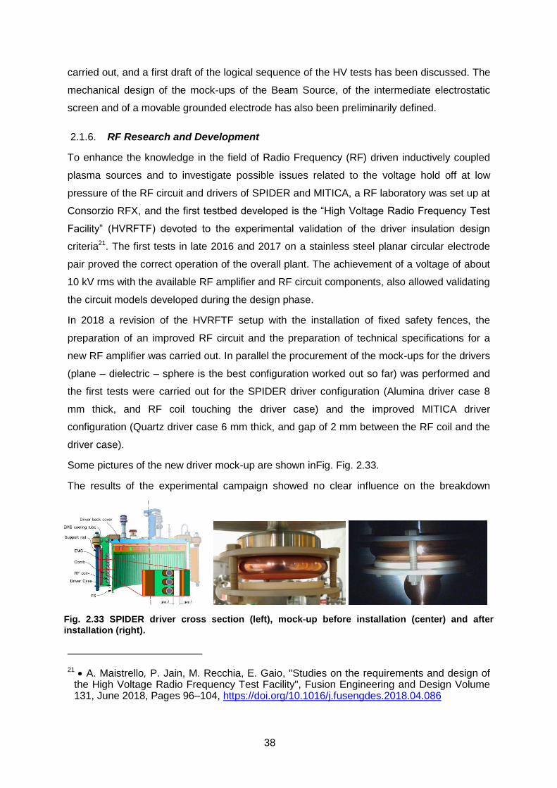
38
carried out, and a first draft of the logical sequence of the HV tests has been discussed. The
mechanical design of the mock-ups of the Beam Source, of the intermediate electrostatic
screen and of a movable grounded electrode has also been preliminarily defined.
RF Research and Development 2.1.6.
To enhance the knowledge in the field of Radio Frequency (RF) driven inductively coupled
plasma sources and to investigate possible issues related to the voltage hold off at low
pressure of the RF circuit and drivers of SPIDER and MITICA, a RF laboratory was set up at
Consorzio RFX, and the first testbed developed is the “High Voltage Radio Frequency Test
Facility” (HVRFTF) devoted to the experimental validation of the driver insulation design
criteria21. The first tests in late 2016 and 2017 on a stainless steel planar circular electrode
pair proved the correct operation of the overall plant. The achievement of a voltage of about
10 kV rms with the available RF amplifier and RF circuit components, also allowed validating
the circuit models developed during the design phase.
In 2018 a revision of the HVRFTF setup with the installation of fixed safety fences, the
preparation of an improved RF circuit and the preparation of technical specifications for a
new RF amplifier was carried out. In parallel the procurement of the mock-ups for the drivers
(plane – dielectric – sphere is the best configuration worked out so far) was performed and
the first tests were carried out for the SPIDER driver configuration (Alumina driver case 8
mm thick, and RF coil touching the driver case) and the improved MITICA driver
configuration (Quartz driver case 6 mm thick, and gap of 2 mm between the RF coil and the
driver case).
Some pictures of the new driver mock-up are shown inFig. Fig. 2.33.
The results of the experimental campaign showed no clear influence on the breakdown
21 A. Maistrello, P. Jain, M. Recchia, E. Gaio, "Studies on the requirements and design of the High Voltage Radio Frequency Test Facility", Fusion Engineering and Design Volume 131, June 2018, Pages 96–104, https://doi.org/10.1016/j.fusengdes.2018.04.086
Fig. 2.33 SPIDER driver cross section (left), mock-up before installation (center) and after
installation (right).

39
voltage of the “gap 2” shown in Fig. 2.33. A new driver mock-up is being prepared and will
be tested to further investigate the matter.
Caesium R&D 2.1.7.
Caesium R&D activities on CATS facility started in 2018: the first campaigns for Cs
characterization were carried out and simultaneously lots of debugging was done on
hardware and software, control and diagnostics. It was possible to start to obtain and
characterize the output of Cs flow from the oven prototype procured in 2017, with regard to
the control of the oven temperature in the reservoir and the duct. Various SPIDER-relevant
diagnostics, like Laser Absorption Spectroscopy and Surface Ionization Detector, were
operated in different conditions.
Further tests to characterize the behaviour of the oven at various parameters were then
carried out, with particular attention focussed on the valve and on the diagnostics, under
different possible conditions in order to give the green light for the production of the series
ovens for SPIDER source, which are being delivered at the end of 2018 for testing on CATS
before being installed on SPIDER.
Caesium is known to accumulate within the space in which it is injected over successive
evaporations when the pump rate is less than the flux of caesium from the oven, which alters
the signals obtained from diagnostic techniques. A mobile surface ionisation detector (SID)
and a microbalance were employed to measure the equilibrium flux of the vessel, and so to
directly measure the increase in the background level of caesium. These measurements can
then be applied to the fixed SID to determine which percentage of the flux measured is due
to the background level, and which is due to the caesium evaporated freshly from the oven.
The mobile SID therefore acts as a reference value, after saturation of the signal is attained.
Furthermore, the SID currents are space charge limited, so must be operated with a large
enough bias to reach a saturation current, whilst in a single probe configuration connected to
ground. The duct and reservoir temperatures of the oven can now be specifically selected to
generate the required flux of caesium from the caesium oven.
2.2. ITER Modelling
In 2018 the contribution to the ITER modelling activities on disruptions have extended the
kind of analysis and simulation results obtained in 2017 with the 3D code M3D for the JET
device, to the ITER case, also considering the presence of a finite population of runaway
electrons.
In 2017 it was shown for JET disruptions that the electromagnetic horizontal force (i.e. that
due to plasma asymmetries ) on the vessel increases, as a function of an increasing current
quench time normalized to the wall penetration time. This ratio for JET is around 8-10, which

40
maximizes the horizontal disruption forces. In ITER instead, being the estimated current
quench of the order of 50 to 150 ms and the wall penetration time of the order of 250-300
ms, the electromagnetic forces are expected to strongly decrease, i.e. forces similar to those
in JET could be predicted, even for the highest plasma current and toroidal magnetic field.
To confirm this, the ITER reference scenario at 15 MA have been simulated 22. The main
results are given in Fig. 2.34. The ITER cases confirm the trend found for JET and the strong
dependence of the forces on the above mentioned ratio between the current quench and the
wall times. One of the concern for ITER is the role of runaway electrons (RE) that can
develop during disruptions, due to the relatively low density (related to the loss of
confinement) and the high electric fields (due to fast changes of the plasma current). Since
the RE electron current tends to be damped slowly, as it is also verified in experiments, this
could change the conclusion about the ITER horizontal wall force. In Fig. 2.34 also cases
where a runaway current is present are shown. The RE have been treated as a fluid and the
Ohm’s law has been modified as23 :
∂ψ/∂t = ∇// Φ – η (J// − J//RE)
where is the poloidal flux and is the electrostatic potential, is the plasma collisional
resistivity and J//, J//RE are the plasma and RE parallel currents.
In Fig.1 the amount of the RE current varies from to be equal to be 1/2 of the plasma current
and accordingly the horizontal force changes.
The smaller force is observed for the smaller
fraction of RE current. The time history of the
relevant quantities is plotted in Fig. 2.35 for the
case where the RE brought 1/2 of the plasma
current.
The model uses some free parameters to
describe the time evolution of the RE and
plasma current. These results are therefore not
self-consistent and have a certain degree of
arbitrariness, since the time evolution of the
plasma and RE currents is, in practice, imposed. In this model the role of RE is simply to
22H. Strauss et.al.,Reduction of asymmetric wall force in JET and ITER including Runaway electrons, 27th IAEA Fusion Energy Conference, (Ahmedabad, India 2018), paper IAEA-CN-TH/4-4.
23 M.N. Rosenbluth, S.V. Putvinski, “Theory for avalanche of runaway electrons in tokamaks”, Nucl. Fusion, 37,1355 (1997).
Fig. 2.34 Horizontal force (in MN) vs cq/
wall for ITER cases with no RE and with
different RE currents, i.e. IRE / Ip =1, 2/3, ½ .
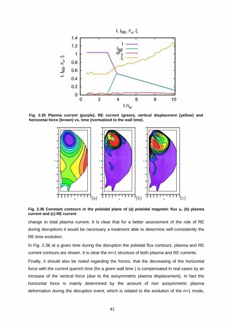
41
change to total plasma current. It is clear that for a better assessment of the role of RE
during disruptions it would be necessary a treatment able to determine self-consistently the
RE time evolution.
In Fig. 2.36 at a given time during the disruption the poloidal flux contours, plasma and RE
current contours are shown. It is clear the m=1 structure of both plasma and RE currents.
Finally, it should also be noted regarding the forces, that the decreasing of the horizontal
force with the current quench time (for a given wall time ) is compensated in real cases by an
increase of the vertical force (due to the axisymmetric plasma displacement). In fact the
horizontal force is mainly determined by the amount of non axisymmetric plasma
deformation during the disruption event, which is related to the evolution of the n=1 mode,
Fig. 2.35 Plasma current (purple), RE current (green), vertical displacemnt (yellow) and
horizontal force (brown) vs. time (normalized to the wall time).
Fig. 2.36 Constant contours in the poloidal plane of (a) poloidal magnetic flux , (b) plasma
current and (c) RE current

42
while the vertical force is simply related to the evolution of the n=0 vertical axisymmetric
plasma movement. The faster this movement, the stronger are the eddy currents induced on
the suroounding structures and on the conducting wall and, as a concequence, the resulting
vertical force.
During year 2018, the study of the pre-disruption phase of an high density, L-mode
discharge of ASDEX Upgrade has been continued. The interest in this type of scenario aims
at avoiding/controlling high density disruptions via ECRH heating24 . This scenario is also a
current topic in the MST-1 EUROfusion program and is very important for ITER. These
disruptions in ASDEX are believed to be dominated by stochastization due to the
superposition of many n=1, high-m harmonics (3≤m≤5) which resonate near the separatrix,
coupled to a dominant m=2, n=1 tearing mode (TM), which is braking and increasing in
amplitude near the final phase of the disruption25.
Electron transport was studied via the guiding center code ORBIT26. Fig. 2.37 shows co-
passing collisionless electron orbits, all with 𝜇 = 0, to show the nature of the resonances.
Clear resonance islands are seen for each n=1 harmonic, as well as a nonlinearly generated
resonance at m/n = 5/2. To study transport 300 eV electrons were launched with a uniform
pitch distribution, at a fixed initial flux surface, and a given pitch angle scattering rate,
consistent with the temperature and density of the discharge considered. The evolution of
the canonical momentum (averaged over a
large number of particles)
⟨(𝑃𝜁(𝑡) − 𝑃𝜁(0))2⟩ = 𝐷𝑡𝑝
was studied as a function of time, to see the
behaviour of the electrons in various
portions of the chaotic domain (red lines in
Fig. 2.37). Within the 2/1 island, transport
was found to be superdiffusive, with p=1.23;
in the resonance layer near the 5/2 island,
transport was strongly subdiffusive, with
p=0.2, while particles in the chaotic domain
of the m=3—5 islands was mildly
24 M. Maraschek, et al., Plasma Phys. Control Fusion 60 (2018) 014047 25 V. Igochine, et al., Nucl. Fusion 46 (2006) 741 26 R.B. White and M.S. Chance, Phys. Fluids 27 (1984) 2455
Fig. 2.37 Poincaré of co-passing, collisionless electron orbits during a pre-disruptive phase of ASDEX Upgrade

43
subdiffusive, with p=0.5. This result27 confirms the traditional picture that the 2/1 island has a
fundamental role in the thermal quench preceding disruption, since it determines fast
electron transport across the island, while the chaotic domain that dominates the outer part
of the plasma is characterized by much slower electron transport.
2.3. ITER DIagnostics
ITER core Thomson scattering 2.3.1.
Design activities of ITER core TS were put on hold in 2018 after closure of the
IO/16/CT/4300001320 ITER contract by end 2017. Afterwards we have been waiting for the
signature, expected early in 2019, of the Procurement Arrangement between IO and F4E to
start the procurement, which will be an open call to industry for the full system. Consorzio
RFX in the meanwhile has continued the contacts with IO and F4E to be ready for
consultancy in the next step and has participated to the design review of the ITER divertor
Thomson scattering.
Diagnostic systems Engineering Services 2.3.2.
During 2018 the two Task Orders launched in 2017 in the framework of the “ITER Diagnostic
Systems Engineering Services” contract have been almost completed.
Concerning the task TO#05 (Engineering and coordination for the Outer Vessel Steady-state
Sensors, PBS 55.A5/A6) the conceptual and preliminary design of the “in-port-plug steady
state sensors” have been completed and approved by ITER-Organization.28 29 For this
activity, CAD models of the magnetic sensor assembly have been developed in collaboration
with ITER Design Office (Fig. 2.39) and FEM thermal analyses have been carried out to
assess the most suitable location of installation for the assembly within the Diagnostic
Shielding Module (DSM) in order to achieve, in the operating conditions expected in ITER,
the same operating temperature relevant for DEMO operations (300°C)
27 G. Spizzo, R.White, M. Maraschek, V.Igochine, G.Granucci, the ASDEX Upgrade Team, 2018 Nucl. Fusion in press https://doi.org/10.1088/1741-4326/aaf07c
28 P. Agostinetti, G. Gambetta, “Conceptual design of the in-vessel steady state sensors”, <RFX-ITERDES-TN-004>, 27/02/2018
29 G. Gambetta, N. Marconato, “Preliminary design of the in-vessel steady state sensors”, <RFX-ITERDES-TN-05>, 05/12/2018

44
In the meantime, the manufacture of the sensor assembly for the Hall sensors prototypes to
be installed on the WEST tokamak,
designed during 2017, has been completed
and is now ready for operation ( Fig.
2.38).30
Concerning the task TO#06 (Update of the
design description and requirement
documentation of the ITER magnetic
diagnostic), the review and update of the
“Design Description Document” of the entire
ITER magnetic diagnostic system, with
particular focus on the system performance
assessment and on the definition of
interfaces with the diagnostic sub-systems,
has been completed in support of the ITER
Diagnostic Team.
30 M.Kocan, et al., “Steady state magnetic sensors for ITER and beyond: Development and final design”, Review of Scientific Instruments 89, 10J119 (2018); https://doi.org/10.1063/1.5038871
Fig. 2.38 Hall sensors system for WEST tokamak: (a) WEST cutaway view (white arrow indicating the Hall sensor holder); (b) Photograph of the holder assembly (total length ~1.5 m) with black arrow indicating the location of the sensor head;
(c) head before the installation of the sensors.
Fig. 2.39 Exploded view of the DSM magnetic sensor case assembly
45
EUROfusion Programme 3.
3.1. RFX-mod: experimental, modeling activities and upgrades
Introduction 3.1.1.
In 2018 the realization of the RFX-mod magnetic front-end modification has started after the
award of the industrial innovation project ‘MIAIVO’, granted by Regione Veneto to Consorzio
RFX in partnership with 3 companies of the Industrial District “Meccanica dell’Alto Vicentino”
(ALCA Technology Srl.; Ettore Zanon Spa.; Sisma SpA) in the framework of the POR-FESR
2014-2020 (Regional Operational Program for the European Regional Development Fund).
The progress in the design and implementation of such improvements, in particular related
to the modification of the main machine components (Vacuum Vessel, Stabilizing Shell and
First Wall) and the adaptation or development of the diagnostic systems, are summarised in
Section 3.1.3 and 3.1.6 respectively.
The research activities concerning RFP physics have also progressed developing along the
two general lines mentioned in 2018 activity program, i.e.:
Discussion of RFX-mod2 scientific program and design of new diagnostic systems
Advancement of RFX-mod data analysis and progress of the RFP modelling activities
Most of planned deliverables have been achieved, except some physiologic re-modulation of
the detailed development of few topics. Among them, it is worth mentioning the MHD
equilibrium and control, where, as reported in Section 3.1.14, a huge amount of work has
been done, though not fully consistent with the planned specific topic; it involves 3D
simulation of the effect of plasma-shell proximity on mode amplitude, real time assessment
of magnetic diagnostics in RFX-mod2, magnetic equilibrium reconstruction.
Analysis of the stabilizing shell gap 3.1.2.
The analysis of the effect of error fields, generated by the unavoidable shell inhomogeneity
due to holes for diagnostic access and toroidal and poloidal gaps for the penetration of the
electric and magnetic fields, is necessary to provide guidelines for the design and
implementation of the shell geometry. A previous study for RFX-mod231 assessed that error
field reduction in a butt-joint concept with active coils would have been very challenging. A
different concept, based on a separate copper sleeve extending over a wide poloidal gap, to
guarantee an insulation margin, has been investigated and compared to the RFX-mod
31 P. Bettini, L. Grando, G. Marchiori, “Feasibility study of a local active correction system of magnetic field errors in RFX-mod”, Fus. Eng. And Des., vol. 96–97 (2015) 649
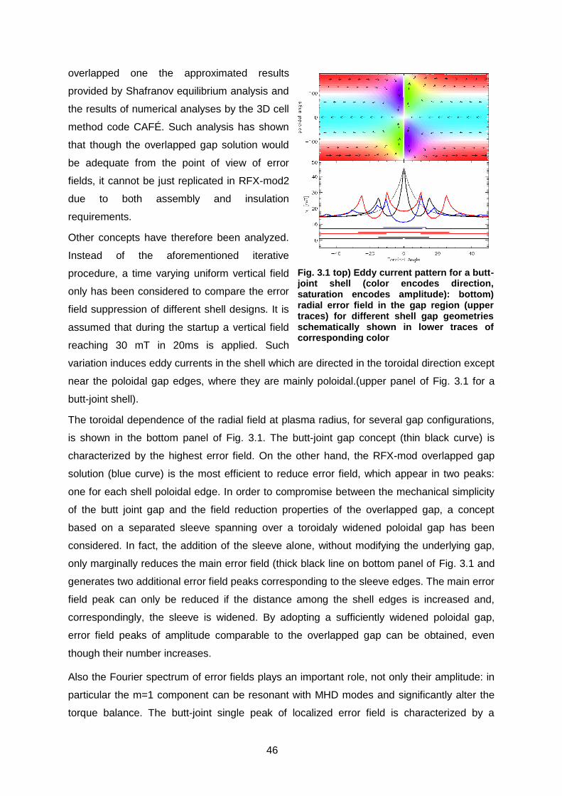
46
overlapped one the approximated results
provided by Shafranov equilibrium analysis and
the results of numerical analyses by the 3D cell
method code CAFÉ. Such analysis has shown
that though the overlapped gap solution would
be adequate from the point of view of error
fields, it cannot be just replicated in RFX-mod2
due to both assembly and insulation
requirements.
Other concepts have therefore been analyzed.
Instead of the aforementioned iterative
procedure, a time varying uniform vertical field
only has been considered to compare the error
field suppression of different shell designs. It is
assumed that during the startup a vertical field
reaching 30 mT in 20ms is applied. Such
variation induces eddy currents in the shell which are directed in the toroidal direction except
near the poloidal gap edges, where they are mainly poloidal.(upper panel of Fig. 3.1 for a
butt-joint shell).
The toroidal dependence of the radial field at plasma radius, for several gap configurations,
is shown in the bottom panel of Fig. 3.1. The butt-joint gap concept (thin black curve) is
characterized by the highest error field. On the other hand, the RFX-mod overlapped gap
solution (blue curve) is the most efficient to reduce error field, which appear in two peaks:
one for each shell poloidal edge. In order to compromise between the mechanical simplicity
of the butt joint gap and the field reduction properties of the overlapped gap, a concept
based on a separated sleeve spanning over a toroidaly widened poloidal gap has been
considered. In fact, the addition of the sleeve alone, without modifying the underlying gap,
only marginally reduces the main error field (thick black line on bottom panel of Fig. 3.1 and
generates two additional error field peaks corresponding to the sleeve edges. The main error
field peak can only be reduced if the distance among the shell edges is increased and,
correspondingly, the sleeve is widened. By adopting a sufficiently widened poloidal gap,
error field peaks of amplitude comparable to the overlapped gap can be obtained, even
though their number increases.
Also the Fourier spectrum of error fields plays an important role, not only their amplitude: in
particular the m=1 component can be resonant with MHD modes and significantly alter the
torque balance. The butt-joint single peak of localized error field is characterized by a
Fig. 3.1 top) Eddy current pattern for a butt-joint shell (color encodes direction, saturation encodes amplitude): bottom) radial error field in the gap region (upper traces) for different shell gap geometries schematically shown in lower traces of corresponding color

47
monotonically decaying broad m=1 spectrum, both with positive and negative toroidal
number n. When multiple error field peaks are present, as for the overlapped gap or the
sleeve gap concepts, an interference effect occurs modulating the spectrum according to the
distance among error field peaks. Two examples are shown in Fig. 3.2. Lower n (n<7)
harmonics correspond to marginally stable or unstable Resistive Wall Modes: even though
the plasma response will likely alter the vacuum harmonics spectrum for these helicities (as
shown in Resonant Magnetic Perturbation studies performed in RFX-mod: see e.g.32), the
RFX-mod MHD control system has routinely
kept these modes at negligible levels. Higher
n harmonics correspond to tearing modes;
their effect on plasma is simulated by means
of the cylindrical, zero pressure, spectral,
RFXlocking code33.The representation of
each m=1/n=7-19 TM eigenfunction is
modified in order to include the effect of the
corresponding error field harmonics, which is
assumed not to alter the mode amplitude at
the resonant surface. The error field is kept
fixed in order to have a conservative
estimate of the effect on tearing mode dynamics in RFX-mod2 and, in particular, of the
locking threshold. A parametric study is performed by considering the error field spectrum for
the overlapped gap multiplied up to 4 times. The average mode rotation frequencies do not
vary significantly unless the error field is multiplied by 4, a value that would imply an
unrealistically high applied vertical field during the startup phase.
Implementation of the machine toroidal assembly modifications 3.1.3.
During 2018 the activities devoted to the modification of RFX-mod experiment have been
further progressed with respect to the design developed in 201734, focussing on the main
components of the machine toroidal assembly, described in the following sub-sections. The
activities have been documented in 8 Technical Reports, submitted to the technical
32 Veranda M. et al., Nucl. Fus 57 (2017) 116029 33 Zanca, P., et al, Plasma Phys. Control. Fusion 51 (2009) 015006 34 S. Peruzzo et al., Detailed design of the RFX-mod2 machine load assembly, Fusion Eng.
and Design, 136 (2018) 1605-1613, https://doi.org/10.1016/j.fusengdes.2018.05.066
Fig. 3.2 Toroidal spectrum of m=1 error field generated by a startup error field
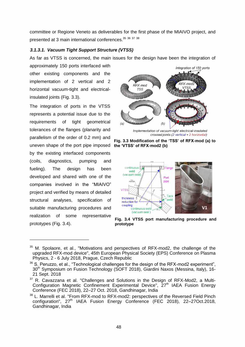
48
Fig. 3.3 Modification of the ‘TSS’ of RFX-mod (a) to
the ‘VTSS’ of RFX-mod2 (b)
committee or Regione Veneto as deliverables for the first phase of the MIAIVO project, and
presented at 3 main international conferences.35 36 37 38
3.1.3.1. Vacuum Tight Support Structure (VTSS)
As far as VTSS is concerned, the main issues for the design have been the integration of
approximately 150 ports interfaced with
other existing components and the
implementation of 2 vertical and 2
horizontal vacuum-tight and electrical-
insulated joints (Fig. 3.3).
The integration of ports in the VTSS
represents a potential issue due to the
requirements of tight geometrical
tolerances of the flanges (planarity and
parallelism of the order of 0.2 mm) and
uneven shape of the port pipe imposed
by the existing interfaced components
(coils, diagnostics, pumping and
fueling). The design has been
developed and shared with one of the
companies involved in the “MIAIVO”
project and verified by means of detailed
structural analyses, specification of
suitable manufacturing procedures and
realization of some representative
prototypes (Fig. 3.4).
35 M. Spolaore, et al., "Motivations and perspectives of RFX-mod2, the challenge of the upgraded RFX-mod device", 45th European Physical Society (EPS) Conference on Plasma Physics, 2 - 6 July 2018, Prague, Czech Republic
36 S. Peruzzo, et al., “Technological challenges for the design of the RFX-mod2 experiment”, 30th Symposium on Fusion Technology (SOFT 2018), Giardini Naxos (Messina, Italy), 16-21 Sept. 2018
37 R. Cavazzana et al. "Challenges and Solutions in the Design of RFX-Mod2, a Multi-Configuration Magnetic Confinement Experimental Device", 27th IAEA Fusion Energy Conference (FEC 2018), 22–27 Oct. 2018, Gandhinagar, India
38 L. Marrelli et al. "From RFX-mod to RFX-mod2: perspectives of the Reversed Field Pinch configuration", 27th IAEA Fusion Energy Conference (FEC 2018), 22–27Oct.2018, Gandhinagar, India
Fig. 3.4 VTSS port manufacturing procedure and prototype

49
One of the most critical aspects in the VTSS assembly is the requirement to guarantee
vacuum tightness and electrical insulation at the present poloidal and toroidal gaps. With the
proposed design solution the two lower and higher VTSS quarters are firstly horizontally tight
jointed (blue seam in Fig. 3.3), by means of existing stud bolts, with interposed semicircular
insulating spacers made of polyether–ether–ketone (PEEK) acting as “half gaskets”; vacuum
tightness is provided by proper “CF knife-edge” machined in the extremely narrow room (8
mm) available on the two surfaces of the mating VTSS quarters. The two VTSS halves are
then vertically jointed with interposed Viton O-rings, for vacuum tightness, and suitable
PEEK and G10 fiberglass spacers for electrical and structural function (red seam in Fig. 3.3).
To veriry this design concept a series of tests have been performed on a dedicated reduced-
scale VTSS mock-up, which initially provided satisfactory results but unfortunately showed
also some failure cases which imply the need of further investigations before freezing the
final design solution. In September 2018, after a detailed metrological survey, which will be
used as reference to assess possible deformations during the following manufacturing
processes, the Stainless Steel Toroidal Support Structure has been delivered to Zanon
workshop (Fig. 3.5).
3.1.3.2. Passive Stabilizing Shell (PSS)
The PSS for RFX-mod2 must be deeply modified, due to the removal of the present vessel,
in order to sustain the new first wall (2016 graphite tiles) and the wide system of in-vessel
diagnostics (more than 1000 electro-magnetic and thermo-mechanical sensors, Section
3.1.6.1) and to operate in vacuum conditions. The design of the new support structure has
been improved with further CAD and FEM analyses. In order to sustain the electromagnetic
loads expected in the worst conditions (plasma fast termination) the thermoplastic support
rings have been reinforced with additional fastening bands and stiffening ribs, which still
provide the suitable electrical discontinuity of the shell along the poloidal direction (Fig. 3.6).
The overlapped gap of the PSS spanning 30° along the toroidal direction, necessary to
minimize magnetic error fields (Section 3.1.2), represents a potential risk of arching between
Fig. 3.5 Loading of TSS at RFX on 6th
Sept. 2018 (left); TSS at Zanon workshop (right)

50
facing edges of the shell, being in contact with weakly ionized gas at the plasma boundary
and potentially exposed to overvoltage of the order of 1 kV during plasma operation39. To
minimize the risk of arching a feasibility study has been carried out aimed at obtaining an
insulating Al2O3 coating on a wide surface of the Cu shell. Among different thermal spray
coating processes, Detonation Gun Spraying (DGS)40 has been selected, for its potential
excellent bond strength, low porosity and cost effectiveness, and it was tested with a facility
available at ENEA Brasimone.
The results obtained on small samples coated with different layers of alumina (Fig. 3.7)
proved the capability to withstand overvoltage up to 2 kV in the operating conditions
expected at plasma boundary during RFX-mod2 operation. To assess the actual reliability of
the process, further tests have been planned, consisting in thermal cycles and mechanical
stress. In the meantime a market survey has been started to assess the availability of
suppliers for the execution of the coating on the entire RFX-mod2 shell with DGS or Air
Plasma Spray as an alternative.
39 R. Cavazzana et al., Design constraints on new vacuum components of RFX-mod2 upgrade using electrical modeling of reversed field pinch plasma, Fusion Engineering and Design, 136 (2018) 1209-1213, https://doi.org/10.1016/j.fusengdes.2018.04.103
40 S. Lakhwinder et al., A Review on Detonation Gun Sprayed Coatings”, Journal of Minerals & Materials Characterization & Engineering, 11 (2012) 243-265
Fig. 3.6 Detail of the components of the PSS assembly (left); Equivalent stress in the PSS
assembly in the worst expected condition (1/72 model of the torus) (right)
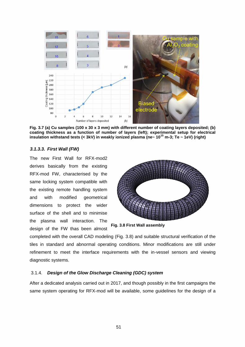
51
3.1.3.3. First Wall (FW)
The new First Wall for RFX-mod2
derives basically from the existing
RFX-mod FW, characterised by the
same locking system compatible with
the existing remote handling system
and with modified geometrical
dimensions to protect the wider
surface of the shell and to minimise
the plasma wall interaction. The
design of the FW thas been almost
completed with the overall CAD modeling (Fig. 3.8) and suitable structural verification of the
tiles in standard and abnormal operating conditions. Minor modifications are still under
refinement to meet the interface requirements with the in-vessel sensors and viewing
diagnostic systems.
Design of the Glow Discharge Cleaning (GDC) system 3.1.4.
After a dedicated analysis carried out in 2017, and though possibly in the first campaigns the
same system operating for RFX-mod will be available, some guidelines for the design of a
Fig. 3.7 (a) Cu samples (100 x 30 x 3 mm) with different number of coating layers deposited; (b) coating thickness as a function of number of layers (left); experimental setup for electrical insulation withstand tests (< 3kV) in weakly ionized plasma (ne~ 10
15 m-3; Te ~ 1eV) (right)
Fig. 3.8 First Wall assembly
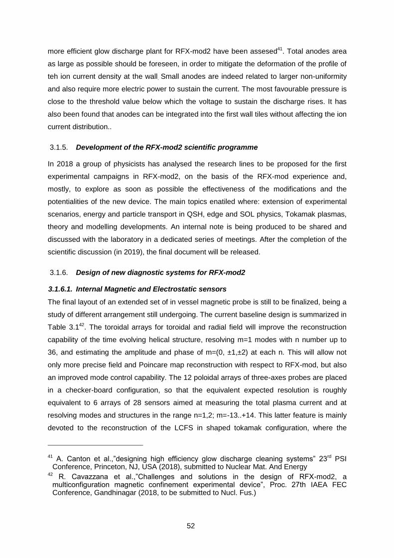
52
more efficient glow discharge plant for RFX-mod2 have been assesed41. Total anodes area
as large as possible should be foreseen, in order to mitigate the deformation of the profile of
teh ion current density at the wall. Small anodes are indeed related to larger non-uniformity
and also require more electric power to sustain the current. The most favourable pressure is
close to the threshold value below which the voltage to sustain the discharge rises. It has
also been found that anodes can be integrated into the first wall tiles without affecting the ion
current distribution..
Development of the RFX-mod2 scientific programme 3.1.5.
In 2018 a group of physicists has analysed the research lines to be proposed for the first
experimental campaigns in RFX-mod2, on the basis of the RFX-mod experience and,
mostly, to explore as soon as possible the effectiveness of the modifications and the
potentialities of the new device. The main topics enatiled where: extension of experimental
scenarios, energy and particle transport in QSH, edge and SOL physics, Tokamak plasmas,
theory and modelling developments. An internal note is being produced to be shared and
discussed with the laboratory in a dedicated series of meetings. After the completion of the
scientific discussion (in 2019), the final document will be released.
Design of new diagnostic systems for RFX-mod2 3.1.6.
3.1.6.1. Internal Magnetic and Electrostatic sensors
The final layout of an extended set of in vessel magnetic probe is still to be finalized, being a
study of different arrangement still undergoing. The current baseline design is summarized in
Table 3.142. The toroidal arrays for toroidal and radial field will improve the reconstruction
capability of the time evolving helical structure, resolving m=1 modes with n number up to
36, and estimating the amplitude and phase of m=(0, ±1,±2) at each n. This will allow not
only more precise field and Poincare map reconstruction with respect to RFX-mod, but also
an improved mode control capability. The 12 poloidal arrays of three-axes probes are placed
in a checker-board configuration, so that the equivalent expected resolution is roughly
equivalent to 6 arrays of 28 sensors aimed at measuring the total plasma current and at
resolving modes and structures in the range n=1,2; m=-13..+14. This latter feature is mainly
devoted to the reconstruction of the LCFS in shaped tokamak configuration, where the
41 A. Canton et al.,”designing high efficiency glow discharge cleaning systems” 23rd PSI Conference, Princeton, NJ, USA (2018), submitted to Nuclear Mat. And Energy
42 R. Cavazzana et al.,”Challenges and solutions in the design of RFX-mod2, a multiconfiguration magnetic confinement experimental device”, Proc. 27th IAEA FEC Conference, Gandhinagar (2018, to be submitted to Nucl. Fus.)
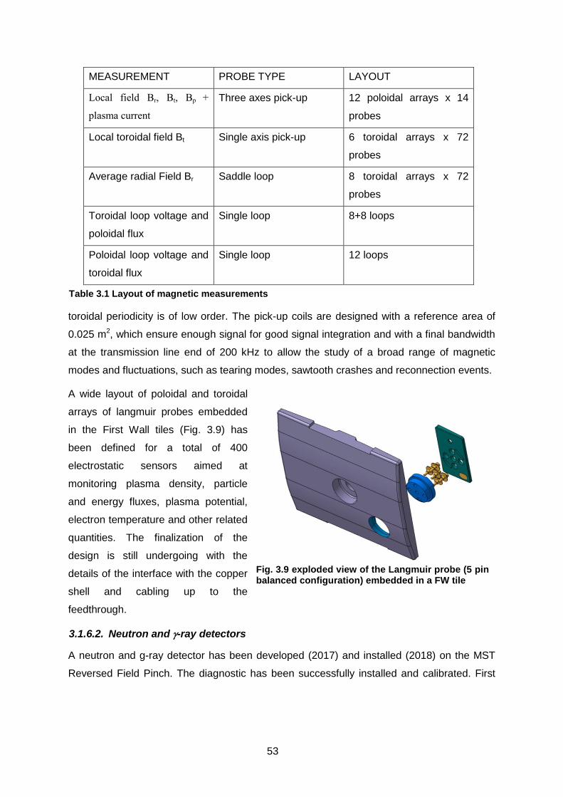
53
toroidal periodicity is of low order. The pick-up coils are designed with a reference area of
0.025 m2, which ensure enough signal for good signal integration and with a final bandwidth
at the transmission line end of 200 kHz to allow the study of a broad range of magnetic
modes and fluctuations, such as tearing modes, sawtooth crashes and reconnection events.
A wide layout of poloidal and toroidal
arrays of langmuir probes embedded
in the First Wall tiles (Fig. 3.9) has
been defined for a total of 400
electrostatic sensors aimed at
monitoring plasma density, particle
and energy fluxes, plasma potential,
electron temperature and other related
quantities. The finalization of the
design is still undergoing with the
details of the interface with the copper
shell and cabling up to the
feedthrough.
3.1.6.2. Neutron and -ray detectors
A neutron and g-ray detector has been developed (2017) and installed (2018) on the MST
Reversed Field Pinch. The diagnostic has been successfully installed and calibrated. First
MEASUREMENT PROBE TYPE LAYOUT
Local field Br, Bt, Bp +
plasma current
Three axes pick-up 12 poloidal arrays x 14
probes
Local toroidal field Bt Single axis pick-up 6 toroidal arrays x 72
probes
Average radial Field Br Saddle loop 8 toroidal arrays x 72
probes
Toroidal loop voltage and
poloidal flux
Single loop 8+8 loops
Poloidal loop voltage and
toroidal flux
Single loop 12 loops
Table 3.1 Layout of magnetic measurements
Fig. 3.9 exploded view of the Langmuir probe (5 pin balanced configuration) embedded in a FW tile

54
results have been presented at 2nd Asia-Pacific Conference on Plasma Physics (sec. 3.1.12)
43
3.1.6.3. Fast reciprocating manipulator (FaRM)
No specific activity was needed in 2018, the design of the system is ready for procurement,
once budget is assigned
3.1.6.4. Crystal spectrometer
A crystal spectrometer used in the past on FTU44454647 (where a large experience on this
diagnostic is available) will be installed on RFX-mod2, to provide core ion temperature and
possibly rotation velocity- measurements by observing lines from Neon and Argon (to be
puffed/injected into the plasma). The system is based on a Johan scheme. In 2018 a
preliminary study of the layout has been done. Crystals have been obtained via the on-going
JET Dispersal of Assets procedures, while the choice of the detector will be defined in 2019.
3.1.6.5. Temperature and SXR diagnostics
A new beam dump for Thomson scattering laser has been designed, to double the laser path
thus improving signal-to-noise ratio. New Multi Pixel Photon Counte (MPPC) detectors
combined with organic scintillators have been characterised for the RFX-mod2 SXR
diagnostic48. Such detectors proved to work in geometries and energy ranges of interest for
RFX-mod2 (3-10 keV), though the energy discrimination of incident photons is challenging.
To increase the photon budget, a double detector layout could be adopted.-
Loan of the AIST 1MW neutral beam 3.1.7.
The 1 MW neutral beam injector on loan from AIST, Tsukuba, will be applied to RFX-mod2
(in addition to the diagnostic Neutral Beam already installed in RFX-mod) in order to
measure ion temperature and flow and to address the study of the fast ions confinement. In
agreement with our Japanese colleagues the system has been lent free of charge to
Tokamak Energy Ltd, Cullham Innovation Center for a period of three years. The system has
43 L. Cordaro et al.,Neutron-gamma measurements at the Madison symmetric Torus presentation at 2nd Asia-Pacific Conference on Plasma Physics, 2018, Kanazawa, Japan
44 R. Bartiromo, F. Bombarda, R. Giannella, Nucl. Instr. And Methods in Physics Res. B9, 679 (1985)
45 R. Bartiromo, F. Bombarda, R. Giannella, Phys. Rev. A, 32, 531 (1985) 46 D. Pacella, M. leigheb, M. Mattioli, Phys. Scripta 57, 265 (1998) 47 R. Bartiromo, et al., workshop for Diagnosis of Contemporary Fusion Experiments, Book
Series: International School of Plasma Phys. piero Caldirola, vol. 9, pag. 959 48 A. Fassina, P. Franz, 45th EPS Conf. on Plasma Physics, Prague, p. P5.1004 (2018)
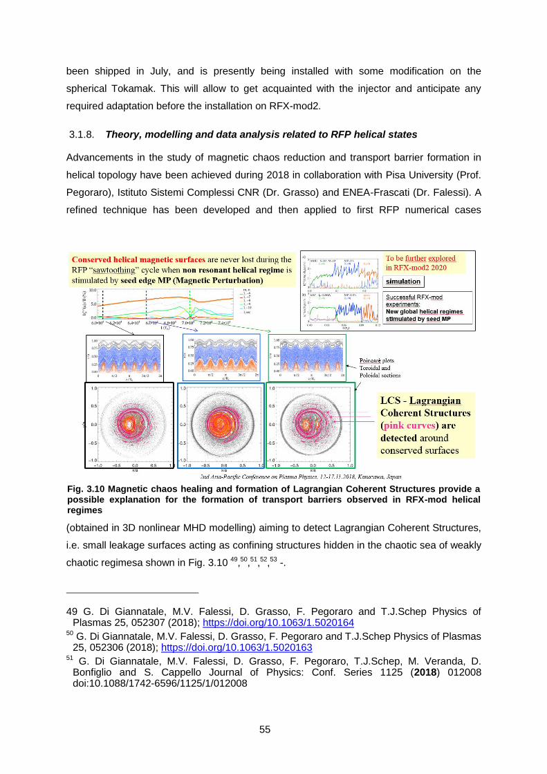
55
been shipped in July, and is presently being installed with some modification on the
spherical Tokamak. This will allow to get acquainted with the injector and anticipate any
required adaptation before the installation on RFX-mod2.
Theory, modelling and data analysis related to RFP helical states 3.1.8.
Advancements in the study of magnetic chaos reduction and transport barrier formation in
helical topology have been achieved during 2018 in collaboration with Pisa University (Prof.
Pegoraro), Istituto Sistemi Complessi CNR (Dr. Grasso) and ENEA-Frascati (Dr. Falessi). A
refined technique has been developed and then applied to first RFP numerical cases
(obtained in 3D nonlinear MHD modelling) aiming to detect Lagrangian Coherent Structures,
i.e. small leakage surfaces acting as confining structures hidden in the chaotic sea of weakly
chaotic regimesa shown in Fig. 3.10 49,50,51,52,53 -.
49 G. Di Giannatale, M.V. Falessi, D. Grasso, F. Pegoraro and T.J.Schep Physics of Plasmas 25, 052307 (2018); https://doi.org/10.1063/1.5020164
50 G. Di Giannatale, M.V. Falessi, D. Grasso, F. Pegoraro and T.J.Schep Physics of Plasmas 25, 052306 (2018); https://doi.org/10.1063/1.5020163
51 G. Di Giannatale, M.V. Falessi, D. Grasso, F. Pegoraro, T.J.Schep, M. Veranda, D. Bonfiglio and S. Cappello Journal of Physics: Conf. Series 1125 (2018) 012008 doi:10.1088/1742-6596/1125/1/012008
Fig. 3.10 Magnetic chaos healing and formation of Lagrangian Coherent Structures provide a possible explanation for the formation of transport barriers observed in RFX-mod helical regimes
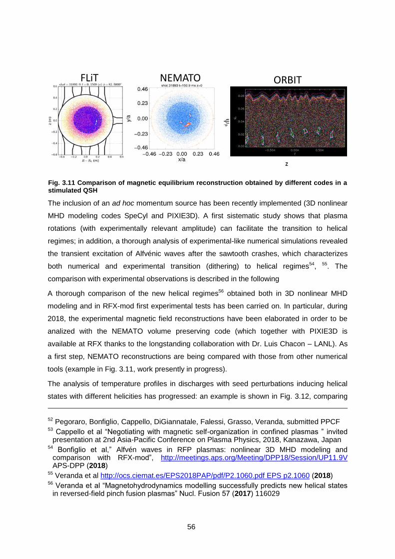
56
The inclusion of an ad hoc momentum source has been recently implemented (3D nonlinear
MHD modeling codes SpeCyl and PIXIE3D). A first sistematic study shows that plasma
rotations (with experimentally relevant amplitude) can facilitate the transition to helical
regimes; in addition, a thorough analysis of experimental-like numerical simulations revealed
the transient excitation of Alfvénic waves after the sawtooth crashes, which characterizes
both numerical and experimental transition (dithering) to helical regimes54, 55. The
comparison with experimental observations is described in the following
A thorough comparison of the new helical regimes56 obtained both in 3D nonlinear MHD
modeling and in RFX-mod first experimental tests has been carried on. In particular, during
2018, the experimental magnetic field reconstructions have been elaborated in order to be
analized with the NEMATO volume preserving code (which together with PIXIE3D is
available at RFX thanks to the longstanding collaboration with Dr. Luis Chacon – LANL). As
a first step, NEMATO reconstructions are being compared with those from other numerical
tools (example in Fig. 3.11, work presently in progress).
The analysis of temperature profiles in discharges with seed perturbations inducing helical
states with different helicities has progressed: an example is shown in Fig. 3.12, comparing
52 Pegoraro, Bonfiglio, Cappello, DiGiannatale, Falessi, Grasso, Veranda, submitted PPCF 53 Cappello et al “Negotiating with magnetic self-organization in confined plasmas ” invited
presentation at 2nd Asia-Pacific Conference on Plasma Physics, 2018, Kanazawa, Japan 54 Bonfiglio et al,” Alfvén waves in RFP plasmas: nonlinear 3D MHD modeling and
comparison with RFX-mod”, http://meetings.aps.org/Meeting/DPP18/Session/UP11.9V APS-DPP (2018)
55 Veranda et al http://ocs.ciemat.es/EPS2018PAP/pdf/P2.1060.pdf EPS p2.1060 (2018) 56 Veranda et al “Magnetohydrodynamics modelling successfully predicts new helical states
in reversed-field pinch fusion plasmas” Nucl. Fusion 57 (2017) 116029
Fig. 3.11 Comparison of magnetic equilibrium reconstruction obtained by different codes in a stimulated QSH
FLiT NEMATO ORBIT

57
a Multiple Helicity profile with n=7 and n=6 QSH’s in discharges at the same current (1.2MA)
and density (4 1019m-3); however, this analysis is still in progress and conclusions about a
comparison among different helicities cannot be drawn yet : the analysis will proceed in
2019.
By using Hamiltonian neo-adiabatic theory, it has been shown in a simpified geometry
applicable -for the moment- to Solar Corona heating issue, that, in contrast with standard
views, an irreversible energy transfer from a low frequency Alfvén wave to a charged particle
can take place, and that a single low-frequency Alfvén wave can provide a relevant heating
of this corona 57.
In addition, the contact established in 2018 with experts of the JOREK team at the Course
on non-linear extended MHD code JOREK, in view of our contribution on modelling of JET-
Mitigation of the disruption (section ), offered the opportunity to perform a more general
comparison with the 3DMHD codes available at RFX. In fact, first steps were performed
toward a comparison/benchmarck of the SpeCyl and PIXIE3D codes with the code
“Discontinuous Galerkin Spectral Element Method for nonlinear resistive MHD in 3D
geometry” (under development by Florian Hindenlang and Eric Sonnendruecker at the MPI-
IPP Numerical Methods in Plasma Physics (NMPP) division)58.
57 Escande, Gondret, Sattin; "A single low-frequency Alfvén wave can provide a relevant heating of the solar corona", submitted PRL ; preprint available HAL: https://hal.archives-ouvertes.fr/hal-01929112 (2018)
58 F. Hindenlang visit 2018/10/15-19 - RFX seminar 2018/10/16 (2018)
Fig. 3.12 Electron temperature profiles from Thomson scattering in a Multiple Helicity ( black), n=7 QSH (green) and n=6 QSH (red)
58
Assessment of RFP scaling laws 3.1.9.
RFX-mod database has been further analysed as a basis for a preliminary design of a hybrid
reactor with a RFP fusion core. In particular, a scaling of electron temperature with current
density as Te J1.1 has been assessed. From such relation, and assuming Spitzer-like
resistivity dependence (Te5/2 JE ) and no dependence of E on minor radius, the following
loop voltage scaling is obtained: V R Ip-0.65 a-0.35.
Based on such scaling, a preliminary design of a FFH reactor wibased on a RFP magnetic
configuration shows on the electromagnetic side the possibility to reach 20 MA plasma
current with presently available technologies, which can be combined to the relatively
simplicity of this solution both as construction and for remote maintenance59.
Transport studies 3.1.10.
Microturbulence studies. In 2018 the activity in microturbulence was planned to be
basically on the relation between microtearing modes and electron transport barrier. Actually
the studies have been focused on the behaviour of microtearing (MT) and also electron
temperature gradient (ETG) driven instabilities in helical states60,61. Helical states in the RFP
have positive impact on the performance, including the occurrence of electron transport
barriers with strong temperature gradients. However, in presence of such strong gradients,
which are related to reduced stochastic transport, radially localized microturbulence is likely
to devolop becoming important as transport driving mechanism in the region surrounding the
helical core. In fact, in previous years it was found that in helical states the ITG
microturbulence growth rate is higher than in axisymmetric states62. In 2018 the gyrokinetic
GENE code applied too the magnetic equilibria calculated by VMEC+GIST has been used to
focus on ETG instabilities at 0 and 0 with realistic magnetic 3D equilibria. Both MT
and ETG modes have been found to be unstable only across the barrier.
Compared to the axisymmetric case, as for ITG it has been found that both MT and ETG
modes have higher growth rates (with ETG particularly stabilized in the axisymmetric case),
see an example in Fig. 3.13, where solid lines corerspond to MT and dashed lines to ETG.
59 R. Piovan et al., 3th Int. Conf.on fusion Neutron Sources and Subcritical fission systems (FUNFI), Hefei, anhui, China (2018), invited talk
60 Predebon I. et al., Asia-Pacific Conference on Plasma Physics, Kanazawa, Nov.12-17 2018 (2018)
61 Predebon I. et al.,Joint Varenna-Lausanne Int. Workshop on Theory of Fusion Plasmas, Varenna,Aug.27-31 2018 (2018)
62 M. Zuin et al., Nucl. Fusion 57 102012 (2017)

59
Transport in presence of magnetic
islands. MT modes have also been
experimentally measured in RFX-
mod. Recently, an interpretation
based on such measurements has
been proposed for the results
obtained by the MAXs transport
code63 comparing DAx (Double Axis)
and SHAx (Single Helical axis)
plasmas. MAXs is a code based on a
Multiple Domain Scheme which
allows the description of transport in
presence of magnetic islands. It has
been applied both to RFX-mod and
LHD plasmas. More specifically, the
thermal diffusivity corresponding to
the temperature gradient region in
DAx and SHAx plasmas have been
compared (see Fig. 3.15 for the
temperature profiles in the two
regimes). The result is shown in Fig.
3.14, indicating a lower thermal
diffusivity corresponding to DAxs.
Correspondingly, different MT
spectra are measured in the two
configurations, with SHAXs related
to a more peaked spectrum. A sound
interpretation will require dedicated
non linear gyrokinetic simulations.
Impurities 3.1.11.
In the perspective of performing
impurity studies in RFX-mod2 exploiting the TESPEL (Tracer Encapsulated Solid Pellet)
diagnostic by the injection of heavy impurities in the plasma core, a modelling activity has
63 F. Auriemma et al., Nucl. Fus.58 096037 (2018)
Fig. 3.13 Growth rate of MT (solid) and ETG (dashed modes in 3D helical geometry (blue) and axisymmetric geometry (green) at the barrier.
Fig. 3.13
Fig. 3.14 Thermal diffusivity in DAx and SHAx RFX-mod plasmas and, for comparison three experimental MT spectra (green DAx, violet & pink SHA
Fig. 3.15 Comparison of DAx and SHAx magnetic surfaces with the corresponding temperature profiles
)

60
started in 2018. Impurity simulations are currently caaried out by 1D codes (with the usual
radius or with the helical flux as radial coordinate). Such codes are now being modified in
order to include an internal source term. In the meanwhile, an extensive benchmark and
updating of the atomic physics is in progress, comparing ADAS database with data used in
the ITC code.-64
Edge physics and Plasma-wall interaction: 2d filaments dynamics in tokamak 3.1.12.
plasmas
Filaments propagation from the edge to the SOL and vice versa couples the turbulence of
these two regions which might enhance the Scrape-Off-Layer (SOL) fluctuation and the
interaction with plasma-facing components. In addition, the intensification of cross-field
transport provided by filaments might compete with parallel transport and so impact the heat
flux width at the divertor. On the other hand, ExB shear regulates perpendicular velocity,
inhibiting the turbulence growth and decoupling edge-SOL turbulence65. The aim of this work
was to study turbulent filaments in different plasma conditions in the RFX-mod running as a
tokamak; from the regular ohmic L-mode to H-mode: ELMy and free-ELMs (both induced by
biasing technique). Results reported here were presented at the EPS conference 2018
6667and preliminary results on 2D features of ELMy bursts observed in RFX-mod tokamak
were reported in68 . The 2D filament dynamics was captured through measurements with the
U-probe by applying conditional average in the extreme events of an ion saturation current
signal (Is) considered as reference. Fig. 3.16 shows the Is blob dynamics in different radial
position (at the top) and the floating potential (Φf) map at different time slices (at the bottom),
both showing outward propagation. 2D cross-correlation was applied to obtain their 2D
64 M. Mattioli et al., J. Of Phys. B: Atomic Mol. Opt. Phys., 37, 13 (2004) 65 M. Spolaore,, et al.. Nuclear Fusion, 57(11), 116039 (2017). 66 Grenfell, M. Spolaore et al. 2-D filament dynamics in high and low shear flows in the edge
of the RFX-mod tokamak 45th EPS Conference on Plasma Physics, July 2-6,2018, Prague, P2.1101 (2018)
67 G. Grenfell, M. Spolaore, B. Van Millingen, C. Hidalgo, Electromagnetic turbulence in the edge of fusion plasmas: spontaneous and actively modulated features, ITER PhD event, Cadarache, November 6-9, 2018
68 M. Spolaore, K. Kovaric, G. Grenfell et al. ELM electromagnetic fine structure in tokamak discharges, Workshop on Electric Fields, Turbulence and Self-Organization in Magnetized Plasmas (EFTSOMP), Prague 9-10 July 2018, invited contribution (2018)
Fig. 3.16 The conditional average of filaments detected with the threshold criterion seen by a) the ion saturation signals (the redline is the reference) and b) 2D floating potential map in four
frames (#39136). The white arrows represent the ExB flow

61
velocity and size, as well as other relevant parameters . In H-mode, filaments are trapped
and dissipated at the shear layer location (Fig. 3.17), while they travel freely into the far SOL
in L-mode, with typically radial velocity of 2.5 km/s. In the ELMy phase, the relaxation of the
transport barrier allows bigger and/or slower structures to endure the background flow shear
and then reach outer regions.
Effect of high n mode locking in helical plasma-wall interaction The effect of toroidal
harmonic m=1 with 7<n<23 (secondary modes) in QSH plasmas has been analysed in
detail69. The secondary modes develop an interfernce pattern which produces a deformation
of the the magnetic field lines in large poloidal lobes. The latter hit the plasma facing
components, resembling the toroidal “homoclinic lobes” observed in the Tokamak divertor
with RMP application.
The local parameter Sk=sec/1/7 (with sec and 1/7 displacements related to local secondary
and dominant modes respectively) has been assumed as a good estimator of the PWI
strength. It has been found to be very well correlated with the global parameter bsec/b1/7,
which is in turn related to core diffusivity70, but in addition also contains information on the
mode phase.
As shown in Fig. 3.18, the condition Sk<0.7 corresponds to bsec/b1/7<0.3 that was found to be
a threshold for the development of electron temperature transport barriers. The relevance of
69 P. Scarin, M.Agostini, G. Spizzo, M. Veranda, “Helical Plasma-Wall interaction in the RFX-mod: effects of high-n mode locking”, Proc. 27th IAEA FEC Conference, Gandhinagar (2018, to be submitted to Nucl. Fus.)
70 F. Auriemma et al., Nucl. Fus. 55 043010 (2015)
Fig. 3.17 Same as previous figure but for the H-mode regime induced by electrode biasing
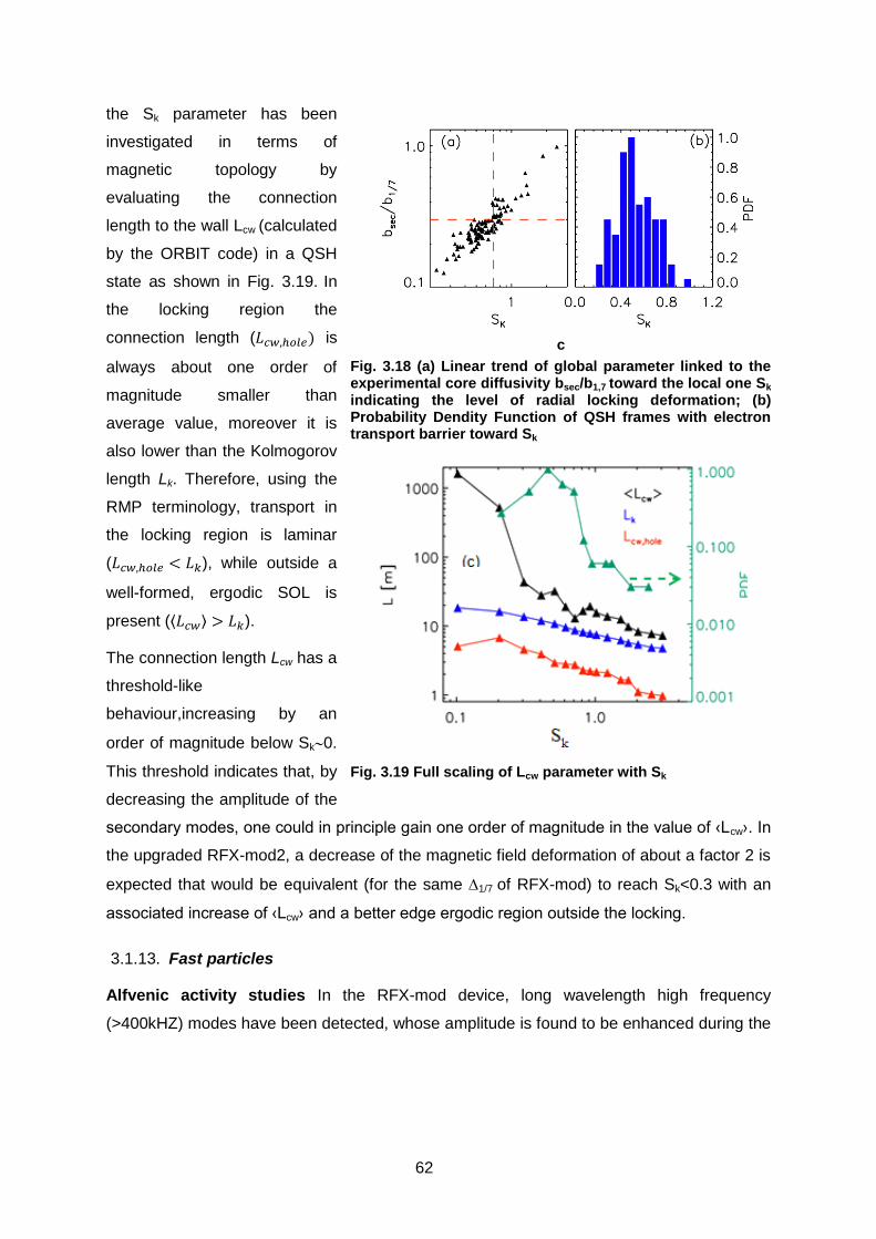
62
the Sk parameter has been
investigated in terms of
magnetic topology by
evaluating the connection
length to the wall Lcw (calculated
by the ORBIT code) in a QSH
state as shown in Fig. 3.19. In
the locking region the
connection length (𝐿𝑐𝑤,ℎ𝑜𝑙𝑒) is
always about one order of
magnitude smaller than
average value, moreover it is
also lower than the Kolmogorov
length Lk. Therefore, using the
RMP terminology, transport in
the locking region is laminar
(𝐿𝑐𝑤,ℎ𝑜𝑙𝑒 < 𝐿𝑘), while outside a
well-formed, ergodic SOL is
present (⟨𝐿𝑐𝑤⟩ > 𝐿𝑘).
The connection length Lcw has a
threshold-like
behaviour,increasing by an
order of magnitude below Sk0.
This threshold indicates that, by
decreasing the amplitude of the
secondary modes, one could in principle gain one order of magnitude in the value of ‹Lcw›. In
the upgraded RFX-mod2, a decrease of the magnetic field deformation of about a factor 2 is
expected that would be equivalent (for the same 1/7 of RFX-mod) to reach Sk<0.3 with an
associated increase of ‹Lcw› and a better edge ergodic region outside the locking.
Fast particles 3.1.13.
Alfvenic activity studies In the RFX-mod device, long wavelength high frequency
(>400kHZ) modes have been detected, whose amplitude is found to be enhanced during the
c
Fig. 3.18 (a) Linear trend of global parameter linked to the experimental core diffusivity bsec/b1,7 toward the local one Sk
indicating the level of radial locking deformation; (b) Probability Dendity Function of QSH frames with electron transport barrier toward Sk
Fig. 3.19 Full scaling of Lcw parameter with Sk

63
spontaneous reconnection processes
characterizing the RFP dynamics71. The
Alfvénic nature of such fluctuation has been
deduced by the linear dependence of the
associated frequency on the Alfvén velocity in
a variety of experimental conditions, with
different plasma current and electron density
values and isotope masses. Moreover, a lower
frequency branch of discrete coherent Alfvén
eigenmodes has been observed to be
destabilized in RFX-mod when the
spontaneous transition from an axysimmetric
to a single helical equilibrium occurs at high
plasma current levels (above 1MA).
In Fig. 3.21 an example is shown of a color-
coded contour spectrogram, i.e. the frequency
power spectrum resolved in time, of a signal
from a single magnetic probe, measuring the
time derivative of the poloidal magnetic field
fluctuation collected in a high plasma current
RFP discharge. The red overplotted curve is
the time behavior amplitude of the amplitude
of the toroidal component of the dominant
m/n=1/7 mode. The power spectrum at a
given time interval, indicated in Fig. 3.21 with a vertical arrow, exhibit five clear coherent
peaks, named a-e, as shown in Fig. 3.21. The first three, at lower frequencies (normally
below 500 kHz) are the ones emerging when the helical axis states form, while the two at
higher frequency are almost ubiquitously present in RFX-mod spectra.
The long wavelength nature of the observed modes has been deduced by applying the two-
point analysis technique to signals coming from high-frequency in-vessel magnetic coils
located in various poloidal and toroidal positions at the edge of the plasma column.
The spectral properties of such instabilities have been compared to those predicted by
dedicated numerical simulations performed with the 3D MHD nonlinear visco-resisitive code
71 ] S. Spagnolo et al., Nucl. Fusion 51, 083038 (2011)
Fig. 3.21 (top) time trace of the plasma current in a RFX-mod shot; (bottom) spectrogram of dBp/dt signal. In red, time trace of the amplitude of the toroidal component of the m/n=1/7 dominant mode
Fig. 3.21 Power spectrum measured around t=85ms (black arrow in fig. 3.4), showing 5
coherent modes

64
SpeCyl. The modeling results suggest
that reconnection processes, which
almost cyclically occur in the RFP
plasmas, can destabilize long
wavelength Global Alfvén eigenmodes,
not damped at radial locations where a
minimum of the Alfvén continuum
occurs, as well as compressional
modes, whose dispersion relation is a
solution of the magnetosonic Alfvén
waves. It is interesting to note that the
compressional branch of the Alfvén
spectrum is normally disregarded in
Tokamak plasmas, because of the
associated very high frequency.
Preliminary results from neutron-
gamma-rays measurements in MST.
The system installed and calibrated in
MST has been operated in a wide
range of operation conditions, both
with and without the injection of a
neutral beam (25 keV, 40 A). As an
example, Fig. 3.22 MST plasma
discharge, from top to bottom: plasma current (black) and loop voltage (red); reversal
parameter (black) and electron density (red); beam voltage and current;signal from the low
rtime esolution neutron-gamma detector; 6 channels (corresponding to 6 lines of sight) from
the new fast system, showing neutron (black) and neutron + gamma (red) signalsshows the
time traces from the six channels of the new detector in a plasma discharge with beam
injection, highlighting the strong improved time resolution with respect to the previously used
detector (also shown).First preliminary analyses show an excellent time resolution and the
capability of the diagnostic of withstanding high neutron and gamma-rays flow, up to several
Mcounts/ms72. The evaluation of the signal decay time after beam switching-off allows the
estimate of the fast particle confinement time.Thanks to the very high time resolution, very
72 L. Cordaro et al., .,”Neutron-gamma measurements at the Madison symmetric Torus” presentation at 2nd Asia-Pacific Conference on Plasma Physics, 2018, Kanazawa, Japan
Fig. 3.22 MST plasma discharge, from top to bottom: plasma current (black) and loop voltage (red); reversal parameter (black) and electron density (red); beam voltage and current;signal from the low rtime esolution neutron-gamma detector; 6 channels (corresponding to 6 lines of sight) from the new fast system, showing neutron (black) and neutron + gamma (red) signals

65
fast processes as those occurring at reconnections can be studied, when transient peaks of
both neutron and gamma rays are detected.
MHD equilibrium and control 3.1.14.
3D simulation of mode amplitude dependence on plasma-shell proximity. In order to
predict the m=1 mode scenario for RFX-mod2, a set of SpeCyl simulations have been
performed with Lunquist number S=105, Prandtl number P=10 and different values of the
plasma-shell proximity b/a starting from the reference case b/a=1 (corresponding to the
standard version of the SpeCyl code) up to b/a=1.2. RFX-mod value for shell proximity is
1.11, while RFX-mod2 design corresponds to 1.04.73 It is conservatively assumed that
temperature and loop voltage remain the same throughout the scan. The resistivity of the
wall at plasma radius is very high (more precisely the ratio between the wall time and the
Alfven time w/a=103) so that eddy currents induced into it are negligible on the relevant
simulation time scales.
The simulations are characterized by quasiperiodic sawtooth cycles with reconnection
events: the resonant m=1, n=-7,,-20 are the most active modes whose amplitudes spike at
the reconnection times. It is found that the time averaged edge value of the radial field
associated with these modes grows with the ideal shell distance, starting from zero for the
reference case in which the ideal shell corresponds to the plasma edge (b/a=1). Fig. 3.23
shows the scaling of normalized edge and
volune integrated amplitude of m=1 modes as
obtained by Specyl as a function of plasma-
shell proximity. Also predicted (and shown in
the same figure) is a reduction of overall mode
energy of about 30% for RFX-mod2 compared
to RFX-mod suggesting a decrease of internal
transport
Real time assessment of the magnetic
diagnostics in RFX-mod2. The magnetic
diagnostic system in fusion devices plays a
critical role in both real time plasma control and
off line in-depth analysis as it provides the most relevant information for the reconstruction of
the plasma shape and position. The failure or malfunction of one or more components can
73 L. Marrelli et al., Proc. 27th IAEA FEC Conference, Gandhinagar (2018, to be submitted to Nucl. Fus.)
Fig. 3.23 scaling of normalized edge and volume integrated amplitude of m=1 modes as obtained by Specyl as a function of
plasma shell proximity

66
cause negative consequences in several applications, including plasma equilibrium and
stability control.
Usually their assessment is carried out by suitably operating the devices in dry discharges or
in well controlled plasma conditions and suitable calibration coefficients are introduced. This
procedure was applied to RFX-mod for both reverse field pinch and tokamak discharges in
order to set a reliability flag to magnetic measurements after each discharge. This system is
presently applied only to Bt measurements using the expected waveforms applied to the
system before the plasma is actually produced. However this leaves to the operator the
assessment of the coils measuring other components of the magnetic field.
In the paper from Chiariello74 a new procedure has been proposed able to provide a check
up of all the main magnetic diagnostics (e.g. local probes, saddle coils and flux loops), to
identify the probes to be investigated, to provide each component with a reliable confidence
coefficient and, finally, to suggest reasonable corrections of the actual measurements. In this
approach a complete description of the plasma behavior is not needed in order to reduce the
computational burden, a linear plasma model can be adopted based on the equivalent
plasma currents model74-75-76: an equivalent current density on a suitable toroidal surface is
introduced, and its density is expressed as a truncated Fourier Series. The methodology is
based on a “mirror” operator performing two main actions; a first, inverse action models the
unknown sources including the plasma equivalent currents, and a second, direct action
reconstructs the magnetic field in the region of interest. The capability of the representation
in the first inverse step can be suitably calibrated to bring out, in the second direct step, the
discrepancies to be interpreted as faults or malfunctioning.
First test have been done for some RFX-mod discharges in order to test the feasibility of this
approach and possibly consider a future implementation in real-time
Equilibrium reconstruction for a shaped tokamak. The computation of plasma
equilibrium at RFX is addressed with different codes assuming a fully numerical or semi-
analytical approach. In the framework of the latter situation in the case of Reversed Field
Pinch discharges, the NCT code was developed77 providing a reconstruction based on a
perturbative approach in toroidal geometry. A similar procedure was devised to provide
74A.G. Chiariello, A. Formisano, F. Ledda, R. Martone and F. Pizzo, IEEE Transactions on Magnetics 54 (3) (2018) 1-4
75J. Luo, Plasma Science and Technology 4 (2) (2002) 76P. Bettini, A.G. Chiariello, A. Formisano, F. Ledda, G. Marchiori, R. Martone, F. Pizzo, D.
Terranova, Fusion Engineering and Design 123 (2017) 546-550 77 P. Zanca and D. Terranova, Plasma Phys. Control. Fusion 46 (2004) 1115

67
equilibria for the tokamak configuration taking into account a parametric representation of a
coordinate system suitable for describing a shaped tokamak in toroidal geometry78:
R(r,)=R0+(r)+[r-E(r)]cos()+(r)cos(2)
Z(r,)=[r+E(r)]sin()-(r)sin(2)
Where R and Z are the usual coordinates, E and are representative of plasma elongation
and triangularity, and is poloidal angle. As in previous work, parallel current density is
modelled with a two-power representation providing an adequate solution to represent
shaped configurations with up-down symmetry.
Given that this approach is based on a
perturbative analysis, the work addressed also
the range of values that can be allowed to the
free parameters (E and ) before the starting
assumptions are broken. An example for a test
case is presented in Fig. 3.24 representative of
a JET discharge.
Magnetic equilibria reconstruction in the
RELAX RFP. Experimentally measured states
in the low aspect ratio (R/a=2) RELAX device
have been compared with a cylindrical
relaxation theory79. the experimental states
have not been found to be consistent with the theoretical predictions, in particular in plasmas
with large reversal of the edge toroidal field. Further investigations, in collaboration with KIT,
should clarify these points in 2019.
78 R. Fitzpatrick et al., Nuclear Fusion 33 (1993) 10 79 R. Paccagnella, S. Masamune, A. Sanpei, Phys. of Plasmas 25 072507.(2018)
Fig. 3.24 Reconstructed equilibrium for
some representative JET parameters.
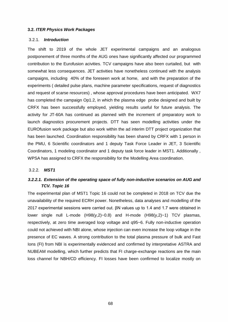
68
3.2. ITER Physics Work Packages
Introduction 3.2.1.
The shift to 2019 of the whole JET experimental campaigns and an analogous
postponement of three months of the AUG ones have significantly affected our programmed
contribution to the Eurofusion acivities. TCV campaigns have also been curtailed, but with
somewhat less consequences. JET activities have nonetheless continued with the analysis
campaigns, including 40% of the foreseen work at home, and with the preparation of the
experiments ( detailed pulse plans, machine parameter specifications, request of diagnostics
and request of scarse resources) , whose approval procedures have been anticipated. WX7
has completed the campaign Op1.2, in which the plasma edge probe designed and built by
CRFX has been successfully employed, yielding results useful for future analysis. The
activity for JT-60A has continued as planned with the increment of preparatory work to
launch diagnostics procurement projects. DTT has seen modelling activities under the
EUROfusion work package but also work within the ad interim DTT project organization that
has been launched. Coordination responsibility has been shared by CRFX with 1 person in
the PMU, 6 Scientific coordinators and 1 deputy Task Force Leader in JET, 3 Scientific
Coordinators, 1 modeling coordinator and 1 deputy task force leader in MST1. Additionally ,
WPSA has assigned to CRFX the responsibility for the Modelling Area coordination.
MST1 3.2.2.
3.2.2.1. Extension of the operating space of fully non-inductive scenarios on AUG and
TCV. Topic 16
The experimental plan of MST1 Topic 16 could not be completed in 2018 on TCV due the
unavailability of the required ECRH power. Nonetheless, data analyses and modelling of the
2017 experimental sessions were carried out. βN values up to 1.4 and 1.7 were obtained in
lower single null L-mode (H98(y,2)~0.8) and H-mode (H98(y,2)~1) TCV plasmas,
respectively, at zero time averaged loop voltage and q95~6. Fully non-inductive operation
could not achieved with NBI alone, whose injection can even increase the loop voltage in the
presence of EC waves. A strong contribution to the total plasma pressure of bulk and Fast
Ions (FI) from NBI is experimentally evidenced and confirmed by interpretative ASTRA and
NUBEAM modelling, which further predicts that FI charge-exchange reactions are the main
loss channel for NBH/CD efficiency. FI losses have been confirmed to localize mostly on

69
outer midplane using ASCOT code.80It was confirmed that internal transport barriers, which
are expected to maximize the bootstrap current fraction, have not been formed in either the
electron or the ion channel in the plasmas explored to date, despite a significant increase in
the toroidal rotation and FI fraction with NBI, which are known to reduce turbulence.
CRONOS modeling is being carried out to investigate this evidence. The results of this work
was presented at the 27th IAEA FEC
conference81.
3.2.2.2. Density Limit
The power-balance density limit (DL) model
presented in 82 has been compared to high-
density disrupted L-mode discharges perfomed
in TCV within the T-25 campaign. The model is
compatible with the experiments, but the
comparison is not definitive due to doubts about
the Zeff signal provided on these shots 83. A
similar analsyis has been carried out on JET
high-density disrupted L-mode discharges: the
model describes fairly well the maximum
observed densities, much better than the
empirical nG criterion, by including radiation
losses from impurities and edge neutrals Fig. 3.25 84.
3.2.2.3. Filamentary transport in high-power H-mode conditions and in no/small-ELM
regimes to predict heat and particle loads on PFCs for future devices- Topic 21
The investigation of filamentary transport in high density regimes in MST1 devices has
continued during 2018. The experimental activity has been limited to TCV tokamak, due to
the shifting of the corresponding programme on ASDEX-Upgrade. On TCV a series of NBI
assisted H-Mode discharges, shown in Fig. 3.26, were performed where plasma conditions
80 M. Vallar et al., Nonlinear contribution of neutral beam injection in TCV EC-heated advanced tokamak scenarios, 45th EPS conference on plasma physics, Prague, 2018
81 C. Piron et al, Extension of the operating space od high-βN fully non-inductive scenarios on TCV using neutral beam injection, 27th IAEA Fusion Energy Conference, Gandhinagar, India 2018
82 P. Zanca et al, A unified model of density limit in fusion plasmas, Nucl. Fusion 57 (2017) 056010
83 P. Zanca et al, L-mode density limit analyses in JET and TCV, internal document NT-FC/91, RFX, Padova (2018)
84 P. Zanca et al, 27th IAEA Fusion Energy Conference, Gandhinagar, India, TH/P5-22
Fig. 3.25 Experimental densities versus modeled DL, for JET, C-wall discharges. Red diamonds mark the disruptions. Grey: D shots. Orange: He shot.
0
0,2
0,4
0,6
0,8
0 0,4 0,8 1,2
<n
e>
(10
20m
-3)
nmodel

70
were varied through gas puff or Nitrogen seeding
with the aim of reaching a detached plasma.
Despite the attempt and the observed increased of
Divertor collisionality div no modification of the
upstream profiles has been observed, consistently
with the fact that the divertor remains attached in all
the explored conditions. In the meantime the
analysis of the database collected on both TCV and
AUG during 2017 continued during 2018.
An investigation has been done in order to
determine the dependence of shoulder formation on
current by performing current scan in L-Mode both
at constant toroidal field and at constant q95. In
ASDEX-Upgrade it has been clearly demonstrated
that the observation of the onset of shoulder
occurring earlier in density at lower current can be
well reconciled, both for the upstream and for the
target density, in terms of edge Greenwald fraction
(i.e. edge density from interferometer divided by Greenwald density) and this is true for both
the scans as seen Fig. 3.27. The behavior is similar for TCV for the current scan at constant
Bt whereas during the scan at constant q95 no
clear shoulder has been observed at lower
current levels. This has been attributed to the
lack of detachment at lower current and toroidal
field which is presently under investigation.
Concerning the blob behaviour no dependence
on plasma current has been observed nor in
AUG neither on TCV.
It is confirmed that Divertor collisionality is not a
qualifier for the increasing of blob-size or
flattening of upstream profile on TCV. The
investigation of shoulder formation in H-Mode
has continued on AUG with discharges with up
to 5.8 MW of heating power. A clear
dependence of shoulder amplitude has been
observed on mid plane pressure, with flatter
Fig. 3.26 From top to bottom. Plasma current, central density, Dalpha, NBH power, Deuterium fueling and N2 seeding during the H-Mode operation in TCV D
shots.
Fig. 3.27 Top: SOL density normalized to the value at the separatrix Middle row: Outer target density Profile. Bottom row: Divertor collisionality. The color code refer to different current levels, the different columns refer to different value of edge density normalized to Greenwald fraction.

71
profile observed when higher mid plane neutral pressure is observed ((see Fig. 3.28). An
intensive work has been done also for measuring the emission of neutral deuterium in the
divertor region, using two visible cameras with two filters for D and D. They observed the
divertor region from the outboard midplane and they are absolutely calibrated. Since they
observe along lines of sight (LoSs), they measure integrated signals, and in order to obtain a
2D map of emissivity ε, a tomographic algorithm has been developed. In order to introduce
as little as possible a-priori constraints, the pixel method is used, and the inversion is
performed with an iterative algorithm. So far it was possible to observe the movement of the
D_alpha radiation from the inner to the outer target with enhanced radiation in the main SOL
as soon as the shoulder develop.
3.2.2.4. Edge modeling studies in alternative configurations and with varying flux
expansion Topics 24 & 25
Edge modeling has been performed with the SOLEDGE2D-EIRENE code on pulses of
experimental campaigns Topic-24 and Topic-25. For Topic-24 Double Null (DN) divertor
configuration pulses both in L-mode and in H-mode have been analyzed. The main aim was
the evaluation of the transport parameters of DN in different regimes. Modeling evaluation
and validation of transport profiles was done by means of comparison with up-stream,
divertor and spectroscopic measurements. Transport profiles were used to infer density
and/or seeding requirements to achieve detachment. Estimated density and seeding values
will be used in next Double Null experiments. Part of the analysis of double null pulses have
been devoted also to the study of drift effect on the observed top/bottom asymmetries, this is
one of the first assessment of SOLEDGE ability to deal with drifts. For the same Topic-24 a
Fig. 3.28 E-folding length as a function of div (frames on the left) and as a function blob-size (frames on the right). In frames (a) and (b) color code refers to divertor neutral pressure,
whereas in (c) and (d) to midplane neutral pressure
72
modeling activity also started trying to understand why a clear dependence of detachment
threshold on flux expansion was not observed experimentally, differently from what predicted
by simple edge models. For Topic-25 it was continued the effort to model Snow Flake
configurations to assess their advantage with respect to the standard Single null
configuration in terms of lower power load at target and easier detachment.
3.2.2.5. International collaboration
International collaboration missions at General Atomics (USA) have been carried out for
studies of global MHD stability in presence of 3D geometries and kinetic effects. The tools
developed and the expertise gained can be applied to RWM stability/control, plasma
response studies with 3D structures and fields in particular. A special focus has been set on
stability studies of high beta Advanced Tokamak scenarios, with applications ranging from
present day experiments to forthcoming devices e.g. JT-60SA.
An international collaboration has also been exploited for developing a new coupling strategy
between linear MHD plasma response (MARS-F) and 3D boundaries (CARIDDI). This
strategy can account for non-ideal effects for plasma stability.
JET1 3.2.3.
3.2.3.1. LH Transition
A contribution to the study on the role of the ion heating channel in the L-H transition in JET,
has been given in terms of numerical simulations (JETTO+PENCIL/ASCOT withing
JINTRAC suite) within the analysis and modelling task T17-08 L-H transition physics merged
into the task M18-14 Isotope effects on L-H transition power threshold. The work has been
presented first at TTF 2018 meeting85 and also with an invited contribution at APS
conference 201886. The JET power balance analysis at the L-H transition will be also
presented in a dedicated paper. The current understanding is that the presence of a
minimum in plasma density of the L-H power threshold cannot be fully explained by the
direct ion heating and the thermal exchange between electron and ions.
3.2.3.2. Impurity transport studies Task T18-03 and Exp. M18-07
In the context of the task T18-03, the analysis of the impurity behaviour has been extended
from the core to the edge by using the suite of codes COCONUT that couples JETTO for the
85 E. R. Solano, E. Delabie, P. Vincenzi, C. Bourdelle, J. Hillesheim, C. Maggi, P. Carvalho, A. Huber, Power balance analysis at the L to H transition in JET-ILW, TTF, Seville, Spain, September 11-14
86 E. Delabie, et al., Reconciling L-H threshold dependencies on JET-ILW with the ErxB shear mechanism, 2018, APS Conference invited

73
core and EDGE2D for the EDGE,
including models for he ELMs, in such
a way that core transport studies can
be carried out using meaningful
boundary conditions. Particular work
has been devoted to test of gyrokinetic
models in JETTO. Fig. 3.29 shows a
sample result of the W flux at the
divertor simulated by COCONUT.
Preliminary results on the ELM imapct
on W and on the rimpurity penetration
across the pedestal layer have been
presented at the EPS conference in
Prague87. In parallel the preparatory work for the experiment M18-07 ( Impurity transport),
shifted to 2019, has been completed and the technical approval obtained.
3.2.3.3. M18-06 experiment preparation
In the contest of scientific coordination for experiment M18-06 “Impact of inner leg flux
geometry on W influx” pulse design activity has been done. The experiment is recognized to
be very important for the definition of the two JET reference DT scenarios: the baseline and
the hybrid ones, for this reason a detailed and well agree experiment preparation was
required. Experiment definition has been already done for the baseline scenario by selecting
the appropriate reference pulse to be used as starting point for geometry study. In
collaboration with Tuscia University various equilibrium with different flux expansion have
been generated with CRETE-NL code trying to keep fixed in the best way strike point
positions and plasma shape to be ovoid spurious effects. In figures Fig. 3.30 it is show as is
87 M Valisa L Carraro FJ Casson et al http://ocs.ciemat.es/EPS2018ABS/pdf/P2.1096.pdf
Fig. 3.29 Simualtion of W flux at the outer divertor
simulated by COCONUT in a 32 MW JET discharge
Fig. 3.30 Flux surfaces (spaced 3.6 mm at outer mid plane) in divertor region of reference
pulse and with reduced flux expansion (ID1=+5kA).

74
possible to compress flux surfaces toward separatrix with respect the reference pulse to
reduce heat flux on top targets (tanks to a higher distance from separatrix in terms of
magnetic flux). Edge modeling have been performed on the reference pulse and with the
same parameters on generated equilibrium to evaluate the reduction on heat load at the top
divertor target which was recognized to be an important source of tungsten core
contamination. The same activity is presently foreseen for the hybrid scenario also.
3.2.3.4. Real time control tools M18-09
The development and the integration of the RAPTOR suite of codes in the MARTe2
framework on JET was advanced in 2018. The upgrade of the real-time equilibrium
reconstruction EQUINOX code was completed, good agreement is achieved with EFIT
equilibrium modeling for a reference JET baseline discharge, a systematic comparison is
being carried out on a wider database. The integration of EQUINOX in MARTe2 was also
started. A real-time algorithm was implemented to map the diagnostic profiles from
geometric to normalized magnetic coordinates. Furthermore RABBIT, a code capable of
evaluating in real-time the Neutral Beam heating, current drive and fast ion radial deposition,
was integrated in the suite. Data I/O interfaces between the codes of the suite were
developed. Data exchange, storage and visualization is supported by the MDSplus software.
3.2.3.5. Pedestal gyrokinetic stability T17-05
In the framework of task T17-05, deliverable D3 (linear and non-linear gyrokinetic modelling
of pedestal transport; assess whether results are consistent with inter-ELM evolution,
pedestal structure, and limitations on pre-ELM pedestal pressure), the activity related to the
investigation of the isotope effect on pedestal micro-instabilities has further proceeded.
Three discharges have been considered for this purpose, with the aim to compare the
influence of the main gas species in two couples of discharges characterized by the same
stored energy and the same input power. In order to disentangle the isotope effect from
profile effects, we have artificially changed the main ion mass (D to H, and vice versa). An
extensive analysis has been carried out with the gyrokinetic code GENE, from low to high
poloidal wavenumbers (KBM/ITG to ETG range), at different radial wavenumbers (i.e.,
different ballooning angles), across the whole pedestal (i.e., differentiating top and steep
gradient region). In the cases investigated here, electrostatic instabilities turn out to be
dominant, KBMs being marginally unstable at very low wavenumbers. A mixing length
estimate of the resulting transport shows a moderate isotope effect across the steep gradient
region, yielding higher conductivities in H than in D in gyro-Bohm units. Further analysis is
required in 2019, extending our previous analysis to nonlinear simulations.
75
3.2.3.6. 3D equilibrium reconstruction . Task T17-15
Non axi-symmetric configurations are observed in JET on a limited extent during operation
with EFCC, when snake structures appear and in extreme conditions during a disruption
when the plasma undergoes a global 3D distortion. In the latter case in order to sort out
possible asymmetries, attempts of equilibrium reconstuction were done running EFIT++ with
separate octants information. This approach cannot provide a self-consistent view while the
VMEC88 code can address correctly (though with some limitations) this situaiton. This
analysis is presently ongoing along with the improvements in the benchmark with EFIT++
and the modelling of experimental measurements. In this respect, the main issue being
addressed involves the role of passive structures that close to disruptions play an important
role and impose some limitations in the modelling of magnetic data in a straight forward way
using the V3FIT89 code.
3.2.3.7. Isotope effect Exp. M18-23
Isotope effect on transport is one of the key topic in recent years JET activity, with the
foreseen campaigns in pure Trituim (TT) and Deuterium and Tritium mixture (DT). The
transport properties are ruled by many ingredients, one being the plasma rotation: numerical
simulations with TRANSP and NUBEAM have been performed (as part of M18-23
experiment) to assess the NBI injection geometries which provide similar plasma rotation in
plasma with different isotopes and mixture.
3.2.3.8. Prediction of high current performance. Task T17-07
Within M18-01 and M18-02 experiments (baseline scenarios and hybrid scenarios)
interpretative simulations of performing on pulses with the highest neutron yield of the last
campaign (92436 and 92398) hav ebeen carried out to predict the plasma performance at
higher current, field and heating power. TRANSP prediction of the plasma performance for
medium N = 1.9 plasmas has been done, as an alternative route to reach the highest fusion
power in DT plasma. The predictive capability of the Trapped Gyro Landau Fluid (TGLF)
code on hybrid discharges of JET has been investigated. TGLF is coupled to the predictive
version of TRANSP. TRANSP+TGLF have been used to predict the evolution of the hybrid
Deuterium shot 92398, which is the hybrid shot where the highest neutron rate has been
measured. The work is still ongoing since a only a subset of available TGLF options has
been used. In the reference discharges the Ti measurements are not available, hence Ti =
88 S.P. Hirshman and J.C. Whitson, Phys. Fluids 26 3554 (1983) 89 J.D. Hanson, S.P. Hirshman, S.F. Knowlton, L.L. Lao, E.A. Lazarus and J.M. Shields,
Nucl. Fusion 49 075031 (2009)

76
1.25 Te has been assumed. Simulations have been done using the settings agreed on the
wiki page https://users.eurofusion.org/tfwiki/index.php/TGLF_recommended_settings, in
particular Saturation equal 1 is used. When the experimental rotation profile is included,
density and ion temperature are well reproduced, while the electron energy transport is
overestimated, hence too a low electron temperature is calculated. This activity has been
performed within in the T17-07 modelling task.
3.2.3.9. Disruption mitigation: shattered pellets JOREK simulations.
In 2018 a new JET modelling activity started at Consorzio RFX with the participation of D.
Bonfiglio (from the CRFX Theoretical Physics group) to a training course organized by
EUROfusion for the use of the nonlinear 3D-MHD code JOREK. The specific topic proposed
when applying for participation to the JOREK training course was modelling of disruption
mitigation with Shattered Pellet Injection (SPI) in JET. After the training course, D. Bonfiglio
joined the team of JOREK modellers working on this topic, composed by D. Hu (ITER), E.
Nardon (CEA) and A. Pau (Cagliari University). After considering deuterium shattered pellets
90, in 2018 the effect of impurity pellets was studied 91. This modelling activity will continue in
2019 with the study of mixed pellets as planned for the upcoming JET campaigns.
DTT 3.2.4.
Following the constitution of an ad interim project structure, CRFX has been involved in the
process of DTT cost estimates validation, the definition of the day 1 diagnostics package, the
dimensionning of the neutral beam injection, the specification of the power supplies, the
qualification of the pysics targets and the revision of the overall project that should end up in
a new project document in early 2019. Modelling activities of the efficacies of different
divertor solutions have been carried out withing the WP DDT1 workpackage.
3.2.4.1. Beam losses estimation
A rather comprehensive evaluation of fast particle losses of the DTT NNBI has been
undertaken during year 2018. Evaluations have been carried out to support the choice of the
most suitable beam energy and injection angle92. In particular, a set of simulations have
90 D. Hu et al., Nucl. Fusion 58, 126025 (2018) https://doi.org/10.1088/1741-4326/aae614 91 D. Hu et al., “Study of full impurity Shattered Pellet Injection by non-linear 3D JOREK
simulation in JET”, APS-DPP 2018 http://meetings.aps.org/Meeting/DPP18/Session/TP11.76
92 P.Agostinetti, T. Bolzonella, M. Gobbin, P. Sonato, G. Spizzo, M. Vallar, and P. Vincenzi, in 30th Symposium on Fusion Technology (SOFT), Giardini Naxos, Sicily, 2018, poster P1.019

77
been carried out using the METIS93
code, considering the reference single
null (SN) scenario94 with two
tangential NNBI systems. These
simulations show that a beam energy
around 400 keV allows central heating
with enough beam penetration (see
Fig. 3.31a and Fig. 3.31b) and that
large injection angles give a more
balanced heating distribution and
increase current drive (see Fig. 3.31c
and Fig. 3.31d) while decreasing the
shine-through losses (see Fig. 3.31e).
Another important issue when
designing a high-energy NBI system,
is the rapid loss of fast particles in
presence of toroidal magnetic field
ripple95.
The expected ripple in DTT is 0.22%
in the low-field side (normalized to the
field on axis B0), not a large number, if
compared e.g. with standard values
expected in ITER96: the expected
fraction of lost particles (monoenergetic and collisionless) has been calculated with the
Hamiltonian, guiding center (GC) code ORBIT97 using as input the single-null equilibrium for
DTT (with ripple) and the initial ion positions calculated with the above mentioned METIS
code.
The result is that collisionless losses (without shine through, which is not accounted for in
ORBIT) amount to ~4% of injected particles, for energy E = 400 keV and tangency radius Rt
93 J.F.Artaud, et al., Nucl.Fusion 58 (2018) 105001 94 R. Albanese, Nucl. Fusion 57 (2017) 016010 95 R. B. White, et al., in Fusion Energy Conference (Proc. 12th Int. Conf. Nice), vol. 2 (1988)
p.111 96 V.Kiptily, et al., Nucl.Fusion 49 (2009) 065030 97 R.B. White and M.S. Chance, Phys. Fluids 27 (1984) 2455
Fig. 3.31 (a) NBI power and (b) current drive released to the plasma as a function of the injection angle; (c) NBI power and (d) current drive as a function of beam energy; (e) shine-through losses as a function
of angle and energy

78
= 1.77 m. This radius corresponds to
an injection angle 𝛼𝑖𝑛𝑗 = 40°,
measured w.r.t the first wall: this result
is shown in Fig. 3.32(left). These
collisionless losses can be divided in
prompt losses (particles lost in less
than 10 toroidal turns, black) and
ripple losses (red trace, loss time > 10
turns). The contribution of ripple
losses is rather modest, ~0:5%, and
decreases with the injection angle,
meaning that trapped particles are the main channel of losses when ripple is switched on. To
see this, one can plot the loss time, expressed in toroidal turns, as a function of the pitch
parameter, which is the velocity parallel to the field, divided by the total velocity: 𝜆 = 𝑣∥/𝑣.
While prompt losses are insensitive to pitch, ripple losses are localized at 𝜆 = 0.65,
corresponding to particles injected with 𝛼𝑖𝑛𝑗 ∼ 40° (see Fig. 3.32, right panel). These results
indicate that we are in presence of the resonance between trapped particle precession and
ripple periodicity, a collisionless mechanism which in principle can determine the rapid loss
of all high-energy, trapped particles, as found in the 1980’s on TFTR and TORE-SUPRA98:
for this reason, for a beam energy of ~400 keV it is safer to design the beamline with an
injection angle 𝛼𝑖𝑛𝑗 ≳ 40°.
As a consequence of the physics evaluation, the energy of 400 keV was chosen and the
injection angle was increased up to the mechanical limit (considering the presence of the
toroidal field coils) of 39.65° with respect to the direction perpendicular to the first wall. This
angle corresponds to a 30° angle measured with the radial direction at the vacuum vessel.
3.2.4.2. Conceptual design of the Neutral Beam injector for DTT
The main purpose of the Divertor Tokamak Test (DTT) is to study solutions to mitigate the
issue of power exhaust in conditions relevant for ITER and DEMO. The key feature of such a
study is to equip the machine with a significant amount of auxiliary heating power (45 MW) in
order to test different divertor solutions. The experiment shall be able to study different
divertor magnetic configurations and reach a reactor relevant power flow to the divertor. The
proposed mix of heating power foreseen to achieve the target value of 45 MW delivered to
98 R.B.White, Phys. Rev. E 58 (1998) 1774
Fig. 3.32 (left) fraction of prompt losses (black) and same quantity plus ripple losses (red) as a function of injection angle; (right) loss times, expressed as toroidal turns, as a function of the pitch parameter
(normalized parallel velocity)

79
the plasma will be provided by Electron Cyclotron Resonant Heating (ECRH), Ion Cyclotron
Resonant Heating (ICRH) and Negative-ion-based Neutral Beam Heating (NNBH).
In this framework, during 2018 a conceptual design of the DTT Neutral Beam Injector has
been developed at RFX in collaboration with ENEA-Frascati and IFP-Milano.
The design development was driven by integrated physics and engineering evaluations,
aiming at optimizing all the main critical aspects at the same time. Flexibility has been
considered as the main design guideline, following the needs of the DTT experiment.
Efficiency and RAMI have also been considered as guidelines. Most of the adopted
technologies are ITER-like, the main differences from the design of the ITER NBI being the
adoption of a modular beam source and of a hybrid cryogenic-plus-NEG pumping system.
The former solution is foreseen to obtain an easier manufacturing of the grids, to permit a
higher flexibility of the beam and to allow for a smaller testbed facility. The latter one aims at
increasing reliability and availability of the injector, while decreasing the costs.
3.2.4.3. Definition and design of the Divertor Tokamak Test facility
The activities devoted to the design of DTT divertor have performed with three main aims: to
assure that DTT design will allow the installation of the divertor selected by EUROfusion in
2022, to provide the input for the design of the divertor pumping system and finally to
contribute EUROfusion in selecting the divertor configuration that provides the better results
in the power exhaust. To the first aim the various proposed magnetic configuration have
been verified in terms of compatibility with the proposed vessel and wall structures. In
particular to provide the maximum performance with presently foreseen magnetic and
technological solution some modification to the initially proposed vessel and toroidal field
coils shapes have been requested and decided. Uno of the critical aspects of DTT design is
the requested flexibility in terms of compatibility with many divertor configurations and also
liquid metals targets. One element affected that is affected from this requirement is the
divertor pumping system. To design a system with the requested flexibility a collaboration
has been setup with the KIT laboratory, to find the optimum divertor configuration in terms of
high pumping efficiency they will use the results of our edge modeling simulation and their
DIVGAS (Divertor Gas Simulator) code. To last aim of help EUROfusion in selectin the best
divertor configuration a first comparison of the three main divertor configurations SND, DND
and SFD+/SFD- in term of power exhaust have been done with the SOLEDGE2-EIRENE
code. Comparison was performed in pure deuterium and with Neon or Argon seeding.
Without impurity seeding a power scan at high separatrix density has shown that SFD- and
con operate in detached condition at a power about 50% higher than this allowable in SND
see Fig. 3.33). SFD configurations when attached reach higher temperature at strike points
than other configurations (related to higher temperature at separatrix). Neon seeding

80
confirms the advantage of SFD configuration in term of a lower Zeff to reach detachment at
maximum PSOL. As observed in DEMO-ADC modeling SFDs require higher pumping speed
than SND and DND probably related to the more open divertor geometry, this suggest that a
better divertor geometry could further improve this configuration.
WPDTT-AC 3.2.5.
The coordination of the DTT1-AC4 “Power exhaust modelling" has been continued together
with the modelling of the alternative DEMO configurations. With the SOLEDGE2D-EIRENE
edge code have been modeled all the alternative divertor configurations proposed for
DEMO. In particular modeling has been done for Snowflake plus and minus (SFP and SFM),
X-Divertor (XD), Super-X divertor (SXD) and Double null divertor (DND) configurations. In
pure deuterium PSOL power scans have been done for all previous configurations and
reference single Null (SND) one at two density levels using transport parameters (D=0.42
m2/s and =0.18 m2/s) corresponding to a parallel heat flux decay length of ≈3 mm. At
middle separatrix density (nsep=2.4∙1019 m-3) detachment was achieved up to PSOL≈50 MW
in all alternative configurations this can be compared to the much lower value of PSOL≈30
MW allowed to the SND case. Alternative configurations outperform SND one also in term of
peak heat flux providing a lower one at PSOL values close to detachment. Results are
similar at high separatrix density value y (nsep=4.0∙1019 m-3), in this case detachment was
achieved up to PSOL≈85 MW in all alternative configurations and up to PSOL≈75 MW in
SND case. The smaller relative difference between alternative configuration and SND at high
density can probably be attributed to the neutrals effect and the better divertor closure with
considered divertor geometry is probably better in SND case.
Fig. 3.33 Maximum target temperature at inner and outer target for considered divertor configurations

81
WPSA 3.2.6.
3.2.6.1. Enhancement projects: Thomson scattering and VUV spectrometer
Within the collaboration between EU and QST-Japan for the procurement of components for
the JT-60SA experiment, C RFX has contributed in 2018 to drafting the procurement call of
two systems: the core and edge Thomson scattering (TS) diagnostics and the VUV divertor
survey spectrometer. Regarding the TS system, the activity has also been a first step
towards the provision of four subsystems: the collection optics with their mechanical
structure and the laser of edge TS system, the fibers and polychromators for both core and
edge TS systems. In particular CRFX has developed optical design studies of the collection
optics, has coordinated the design of the the mechanical structure, performed by the
Romanian Institute of Atomic Physics (IAP), has performed preliminary design of the
prolychromators, agreed with QST the technical specification of the optical fibers and
proposed a dedicated laser for the edge system. On the front of the VUV spectrometer, the
activity consisted in the definition of possible solutions for the spectrometer and the related
optical coupling compatible with the geometrical and environmental constraints, with the
suggetion to enhance the diagnostic potential from a generic survey to an imaging system.
Late in 2018 Eurofusion has appointed CRFX responsible laboratory for the procurement of
of both TS and VUV spectrometer, partly funded by Eurofusion, partly procured directly by
F4E. The contracts will start in 2019 and are due to be completed in 2020 for the VUV
spectrometer and 2021 for the TS system .
3.2.6.2. Resistive wall modes studies
Extending activities started between 2016 and 2017, Resistive Wall Mode stability studies
have been carried out for the high beta JT60-SA Scenario 5 with the linear codes MARS-F
and MARS-K. With the latter in particular, stabilization of the most unstable n=1 RWM at low
plasma rotation has been found. The stabilizing mechanisms is identified with precession
drift resonance with thermal ions. The effect of plasma flow on kinetic-RWM stability has
been studied with a rotation profile calculated consistently with the JT-60SA beam geometry.
A work summarizing the latest developments on this topic, as well as on active feedback
stabilization, has been presented at the IAEA Fusion Energy Conference99.
99 L Pigatto et al :27th IAEA FEC , Gandhinagar, India, 22-27 October 2018, paper TH/P5-23

82
3.2.6.3. Neutral Beam injection studies
Simulations of NBI injection have continued from 2017, with applications of the ASCOT code
to the JT-60SA reference scenarios (2,3,4,5 as from the Research Plan)100. Activities related
to the evaluation of fast ion losses with the effect of external 3D fields (and plasma
response) have started in 2018 and will be continued in 2019.
WPS1 3.2.7.
3.2.7.1. LHD campaign: transport in magnetic islands and isotope effects
Participation to the LHD Deuterium experimental campaign has been addressed to the study
of the heat and particle transport properties in plasma with islands and to enhance the
comprehension of the isotope effects in stellarators. The later topic is still controversial, since
no strong evidences have been found in previous smaller devices. To study the transport
properties in LHD, heat and cold pulse experiments have been performed in plasma with 2/1
RMP islands. The analysis is ongoing.
The analysis of 2017 experiments, where iced pellets were injected in LHD plasmas with
(1,1) RMP island, have been presented at the 2nd AAPPS-DPP conference, as an invited
talk. In particular a MAxS particle transport analysis has been shown, highlighting that also
for particles the island acts as a low diffusivity region surrounded by a 10 times higher
diffusivity plasma. Fig. 3.34 shows the temporal evolution of the density radial profile
measured by the Thomson Scattering
(stars) compared with the MAxS
predictive simulations (solid line). The
transport coefficients are shown in the
lower panel, where the important
decrease of the diffusivity inside the
island is evident.
3.2.7.2. Procurement Installation
an first use of insertable
probe
During 2018, following the final
approval of the Consorzio RFX design
101 by the IPP Greifswald team, the
100 M Vallar, PDH Thesis 101 P. Agostinetti, et al. "Design of a High Resolution Probe Head for Electromagnetic Turbulence
Investigations in W7-X." IEEE Transactions on Plasma Science (2018).
Fig. 3.34 Temporal evolution of the density radial profile measured by the Thomson Scattering (stars) compared with the MAxS predictive simulations
(solid line

83
High Resolution Probe Head (HRP) to be installed on the W7-X experiment, was built and
finally assembled in Padova, then delivered to W7-X in Greifswald. In particular the aim was
to provide information on parallel current density associated to L-mode filamentary turbulent
structures as well as on ELMy structures in H-mode102,103,104,105. Furthermore the possibility
to measure the time evolution of radial profiles of flow was considered as a further
interesting part of the study, given the strong interplay expected between the turbulent
fluctuation and the average flows. Special attention was devoted to the design of a shield for
magnetic sensors embedded into the probe head, which would allow the magnetic
fluctuation measurements (fmeas 1 MHz) and at the same time the shielding from ECRH
(fECRH=140GHz) used for additional heating. The probe head was then installed on the W7-X
Multi-Purpose fast reciprocating Manipulator (MPM) and successfully commissioned. The
HRP probe was then exploited during the OP1.2b W7-X experimental campaign in July and
October 2018. As an example the spectrograms of different magnetic field component
fluctuations exhibiting a bursty behavior is shown in the right panel of Fig. 3.35. This
phenomenology is consistent with the presence of the localized electromagnetic filamentary
structures [105].
3.2.7.3. Thomson Scattering
In 2018, following previous informal contacts with W7-X researchers, a formal collaboration
has been established between the Thomson scattering teams of RFX and W7-X Teams, with
the purpose of carrying out in W7-X a test the dual-laser, self-calibrating Thomson scattering
technique, proposed for ITER. These experiments will use a new Nd:YAG laser system
operating at 1319 nm, under development for W7-X. In the framework of this collaboration
one CRFX post-doc visited the W7-X group at IPP-Greifswald during the summer 2018 and
collaborated to the TS measurements during the OP1.2b experimental campaign.
WPISA 3.2.8.
In 2018 the new version Universal Access Layer (UAL) has been finalized and is currently
being released. In this context, the activity carried out at RFX has been related to the low
level layer, i.e. the layer that provides direct access to the backend components actually
reading and writing data. In particular two backends have been implemented: MDSplus
102 M. Spolaore,et al. Phys. Rev. Lett. 102, 165001 (2009) 103 N. Vianello et al. Nucl. Fusion 50, 042002 (2010). 104 Furno I., Spolaore M., Theiler C., N. Vianello, et al., Phys. Rev. Lett. 106, 245001 (2011). 105 Spolaore, M., et al. Nuclear Materials and Energy 12 (2017): 844-851.

84
backend for reading and writing data to/from MDSplus pulse files, and Memory backend, for
caching in memory data used in simulation.
3.3. ITER NBI Physics activities and accompanying program
Introduction 3.3.1.
Aimed to train the personnel and to complement the ITER NBI activities at Consorzio RFX
by investigating research lines not included in the main program, during 2018 the
accompanying activity to the ITER NBI program have been carried out by operating the
experiment NIO1, by realizing and operating the alternative ion source ATHENIS and by
developing new numerical tools to tackle the controllability of a NBI system . In the following
the main activities on NIO1 and ATHENIS are presented.
NIO1 Experiment 3.3.2.
The operation of the NIO1 experiment in 2018 was devoted to improve the performances of
the negative ion source in pure volume operation. The aim was to increase the accelerated
current, to reduce the fraction of co-extracted electrons and improve the voltage holding
capability of the acceleration system. This was pursued by exploiting the flexibility of the
machine, mainly by changing the magnetic configurations of the Extraction Grid (EG), of
the front magnet multipole.
The phases of the operation of NIO1 throughout 2018 are described here below.
At the beginning of the year, NIO1 operated in the magnetic configuration with the vertical
field given by the only current flowing in the Plasma Grid (PG) and with an horizontal field in
Fig. 3.35 Left: HRP probe, different views of the probe head: 4 Mach probes radially distributed, 2 set of 5-pins triple probe (2 radial positions), 3 set of 3-axial magnetic coils (2D array). Right: Example of br, bp and bt magnetic fluctuation spectrograms measured in the
W7-X SOL, during OP1.2b experimental campaign.

85
front of the plasma grid of 15 mT.. The extraction grid was equipped with Asymmetric
Deflection Compensation Magnets (ADCM), to minimize the beam deflection. The profiles of
magnetic field in vertical (x axis) and horizontal (y axis) direction along the source axis (z)
are plotted for configuration d in Fig. 3.36. where z=0 corresponds to the knife edge of the
PG apertures. From the operation it resulted that the EG field, which penetrates in the
source volume, was insufficient to limit the co-extraction of electrons.
From 01/03/2018 to 24/04/2018 a shutdown of the machine took place, to substitute the EG
magnets in order to produce a stronger filter field. The pyrex cylinder which separates the
source volume from the RF coil was substituted.
From 24/04/2018 to 16/07/2018 the source resumed operation .
From 16/07/2018 to 26/07/2018 another shutdown took place, to change the magnetic
configuration: the extraction grid was left unaltered, while the front multipole was modified in
order to create a vertical, downwards magnetic field of 5 mT (3 times lower than the previous
one). The (vertical) magnetic filter field created by the plasma grid current (max 3 mT @ 400
A) was found capable of modifying the total field more effectively.
From 26/07/2018 to 09/11/2018 the source resumed operation. The operative capabilities of
the source were limited by an internal short circuit on the bias plate, which prevented it from
being polarized. Moreover, the plasma became more evidently affected by some transient
behaviors, characterized by a rapid (~1÷2 min.) drop in plasma luminosity, correlated to a
dramatic increase (up to a factor 10) of the accelerated current. Each phenomenon was then
followed by a regrowth of plasma luminosity and by a corresponding decrease of the
accelerated current.
From 09/11/2018 to 21/11/2018 a shutdown was performed to solve the bias plate short
circuit, and to modify the PG electric circuit in order to easily switch the current direction, and
so the produced magnetic field.
Fig. 3.36 Vertical (Bx) and horizontal (By) profile of the permanent magnetic filter field in
NIO13.

86
From 21/11/2018 the source resumed operation with the bias plate now operative. It has
been found that the temperature of the pyrex cylinder is strongly affecting the plasma
conditions. The investigation on this phenomenon is ongoing.
The performances of the source in the 3 magnetic configurations adopted in 2018 can be
compared in Fig. 3.37. The plots in the figure show the EG current, which can be assumed
as the coextracted electron current, and the fraction of co-extracted electrons, calculated as
the EG current over the sum of the currents collected on the other grids (PA and repeller)
and on the CFC tile. The modeling activity on negative ion beam acceleration for NIO1 was
improved by considering the effect of the secondary particles produced in the beam gas-
interaction.by the code IbSimu. In particular, the stripping of the primary beam, the ionization
of the background gas and the secondary emission of electrons due to the beam-grids
interactions has been now considered.
The results on the beam-gas and beam-grids interaction were successfully compared to
those obtained by the code EAMCC. The agreement with the experimental from the visible
cameras in the drift region was consistently enhanced and is now quite satisfactory, as
Fig. 3.37 EG current and fraction of coextracted electrons, plotted for each data point collected
in 2018, as function of the extraction voltage.
(a) (b)
Fig. 3.38 (a) Emissivity from beam-gas interaction in the horizontal direction measured by a visible camera at about 400 mm downstream the accelerator. (b) Beam profile along the
horizontal direction at 400 mm downstream the accelerator calculated by IbSimu.

87
shown in Fig. 3.38

88
In order to analyze the space charge compensation (SCC) phenomenon in NIO1, a single
Langmuir probe was installed in the diagnostic tube downstream the accelerator. Data have
been collecting varying the beam current, the beam energy and the pressure in the vacuum
vessel. The latter was varied by switching on and off the NIO1 cryopump. The effect on the I-
V characteristic is given in
Fig. 3.39 a. The different contributions affect different portions of the I-V characteristic and
may be determined by a multi-variable fit. The dependence of the different contributions on
the beam energy is instead given
a b
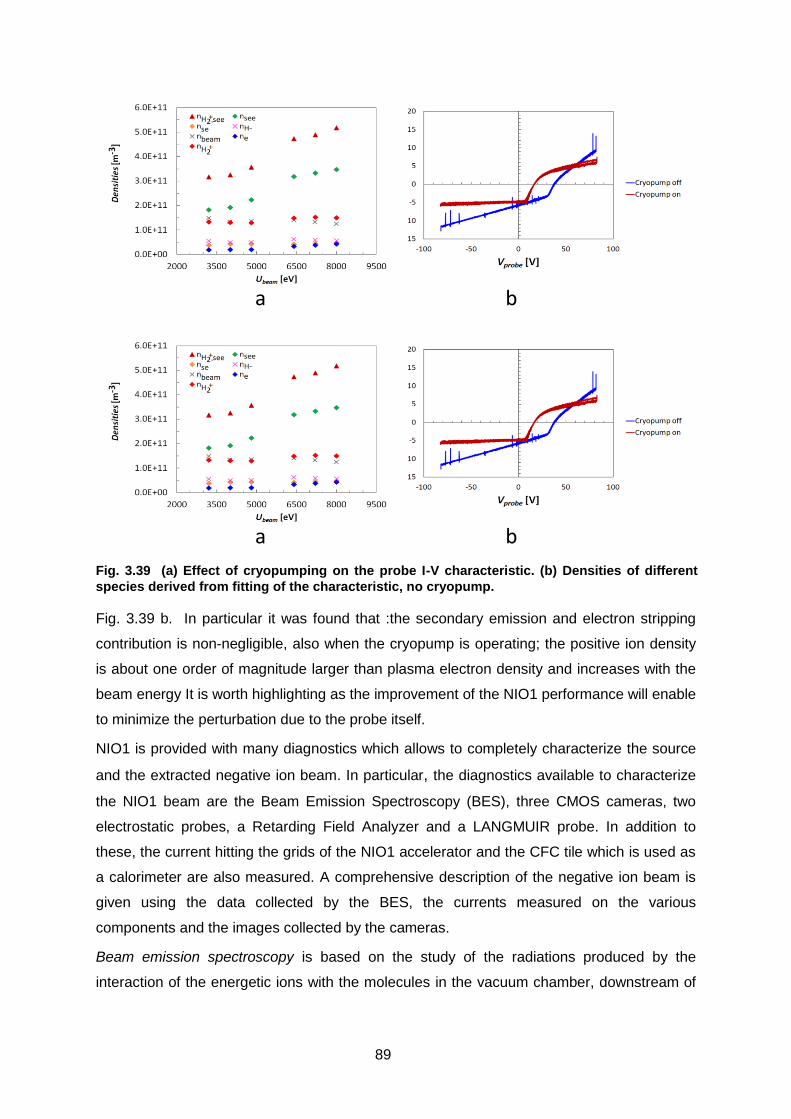
89
Fig. 3.39 b. In particular it was found that :the secondary emission and electron stripping
contribution is non-negligible, also when the cryopump is operating; the positive ion density
is about one order of magnitude larger than plasma electron density and increases with the
beam energy It is worth highlighting as the improvement of the NIO1 performance will enable
to minimize the perturbation due to the probe itself.
NIO1 is provided with many diagnostics which allows to completely characterize the source
and the extracted negative ion beam. In particular, the diagnostics available to characterize
the NIO1 beam are the Beam Emission Spectroscopy (BES), three CMOS cameras, two
electrostatic probes, a Retarding Field Analyzer and a LANGMUIR probe. In addition to
these, the current hitting the grids of the NIO1 accelerator and the CFC tile which is used as
a calorimeter are also measured. A comprehensive description of the negative ion beam is
given using the data collected by the BES, the currents measured on the various
components and the images collected by the cameras.
Beam emission spectroscopy is based on the study of the radiations produced by the
interaction of the energetic ions with the molecules in the vacuum chamber, downstream of
a b
Fig. 3.39 (a) Effect of cryopumping on the probe I-V characteristic. (b) Densities of different
species derived from fitting of the characteristic, no cryopump.
a b

90
the ion source grids. It enables to measure the beamlet divergence, uniformity and direction
of propagation. The beam divergence depends on both the acceleration and extraction
voltage as shown in
Fig. 3.40a, where the minimum of beam divergence in the d configuration shifts towards
higher extraction voltage value as the acceleration voltage increases.
From April 2018, three telescopes are used to monitor the beam evolution. Such telescopes
are installed at different vertical positions in order to characterize also the vertical properties
of the beam. The beamlet divergence obtained is comparable with the beamlet divergence
measured by the single telescope (around 45 mrad as mean value).
The beam emission spectroscopy allows also the measurement of the stripping integral and
emphasize the effect of the cryogenic pumps, with a decrease in the ratio 𝑰𝒔𝒕𝒓𝒊𝒑𝒑 𝑰𝒅𝒐𝒑𝒑𝒍𝒆𝒓⁄
Fig. 3.40 (a) Beam divergence evolution as a function of extraction voltage at different
acceleration voltages. (b) 𝑰𝒔𝒕𝒓𝒊𝒑𝒑 𝑰𝒅𝒐𝒑𝒑𝒍𝒆𝒓⁄ as a function of the acceleration voltage at different
pressures and with/without cryopump.

91
larger than a factor 2.5 (
Fig. 3.40b).
Visible tomography. Tomography aims at measuring the emission or the absorption of
radiation through a large number of lines of sight (LOSs). Beam tomography aims at
measuring beam spatial uniformity which is found to be one of the most difficult issue to
solve.
NIO1 tomography system was composed by two visible CMOS cameras positioned at 90
degrees with respect each other. A third camera was installed in July 2018 in order to
achieve a more complete beam reconstruction: using a mirror inside the NIO1 vacuum
vessel, the third camera is able to see the beam at an angle of almost 80 degrees with
respect the horizontal plane. By fitting the data with three Gaussians it has been possible to
determine the horizontal displacement of the beamlets due to the effect of the filter current. -
Alternative ion Source ATHENIS 3.3.3.
During 2018 ATHENIS (Alternative Thruster Hall Effect Negative Ion Source) has been
completed and operated to test the plasma generated in the source. This alternative scheme
is based on a Hall Effect Thruster (HET), and the HET is used as a plasma generator with
tunable ion energy by means of the operational voltage. According to the project, the source
will be complemented within the end of the year by an extraction system and by a system of
grids to partially shield the plasma and highlight the contribution of the dissociated atoms.
Fig. 3.41 shows a scheme of ATHENIS: the inner diameter is 6mm, the outer diameter is
12.6mm and the length is 58.5mm. The magnetic field is generated by permanent magnet
disks inserted in rings of aluminum (15 magnets for each ring).
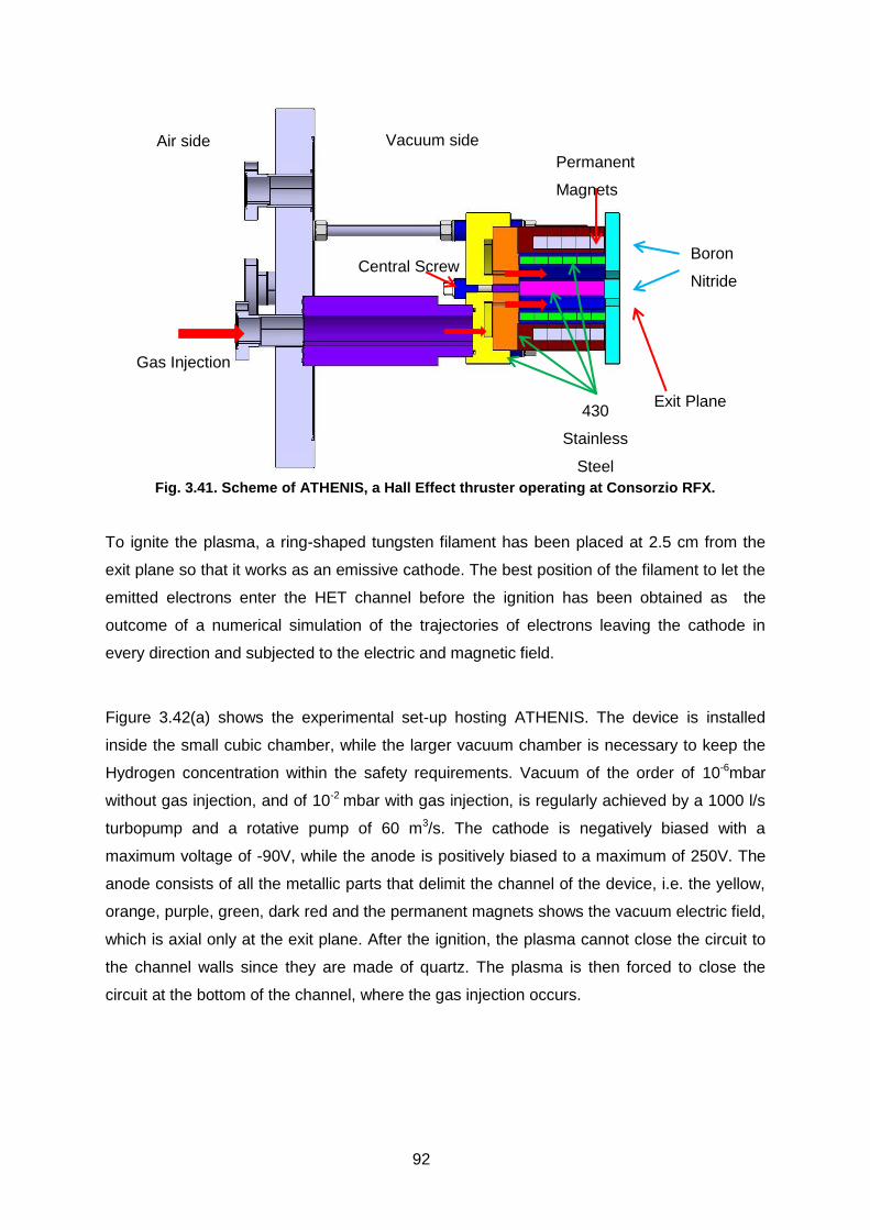
92
Fig. 3.41. Scheme of ATHENIS, a Hall Effect thruster operating at Consorzio RFX.
To ignite the plasma, a ring-shaped tungsten filament has been placed at 2.5 cm from the
exit plane so that it works as an emissive cathode. The best position of the filament to let the
emitted electrons enter the HET channel before the ignition has been obtained as the
outcome of a numerical simulation of the trajectories of electrons leaving the cathode in
every direction and subjected to the electric and magnetic field.
Figure 3.42(a) shows the experimental set-up hosting ATHENIS. The device is installed
inside the small cubic chamber, while the larger vacuum chamber is necessary to keep the
Hydrogen concentration within the safety requirements. Vacuum of the order of 10-6mbar
without gas injection, and of 10-2 mbar with gas injection, is regularly achieved by a 1000 l/s
turbopump and a rotative pump of 60 m3/s. The cathode is negatively biased with a
maximum voltage of -90V, while the anode is positively biased to a maximum of 250V. The
anode consists of all the metallic parts that delimit the channel of the device, i.e. the yellow,
orange, purple, green, dark red and the permanent magnets shows the vacuum electric field,
which is axial only at the exit plane. After the ignition, the plasma cannot close the circuit to
the channel walls since they are made of quartz. The plasma is then forced to close the
circuit at the bottom of the channel, where the gas injection occurs.
Vacuum side Air side
Gas Injection
Boron
Nitride
Permanent
Magnets
Central Screw
Exit Plane 430
Stainless
Steel

93
(a) (b)
Figure 3.42. (a) ATHENIS facility; (b) 3D drawing of ATHENIS assembled parts.
3.3.3.1. Langmuir probe measurements
In order to characterize the plasma generated by the device, a Langmuir probe has been
installed on a z-shifter manipulator. The main results in Nitrogen are shown in Figure 3.43
and Figure 3.44. The temperature and density plots in the bulk plasma, spanning a distance
of 4 cm from the ion source exit, show an almost constant temperature of the order of 3 eV
except for the region near the cathode (see Figure 3.43). Figure 3.44 shows, that density
and temperature values increase with the applied voltage and are uniform over the spatial
range spanned by the probe. From these results it appears, that the voltage plasma
discharge is the main drive of the plasma parameters. To control this parameter, both in
Hydrogen and Nitrogen, it has been found that we have to decrease the cathode current. For
operation in Nitrogen an optimum value of mass flow rate has been found at which plasma
density and electronic temperature reach their maximum value. For the Hydrogen case, only
low values of mass flow rate were considered in order to keep the pressure low enough to
guarantee a mean free path of the H0 atoms of the order of some cm so to allow them to hit
the caesiated target. It has been found that the plasma parameters keep the same trend for
both values of mass flow rate studied, even though a more stable behavior has been
observed for the higher one.

94
(a) (b)
Figure 3.43. (a) Plasma density axial profile for several N2 mass flow rates. (b) Electron temperature axial profile for several N2 mass flow rates. Plasma voltage discharge varies from 65V to 95V with a fixed cathode current of 6.3A. The position of the filament (the cathode) is also shown
(a) (b)
Figure 3.44. (a) Plot of plasma density according to plasma voltage discharge. (b) Plot of electronic temperature according to plasma voltage discharge. Current plasma discharge varies from 0.4A (65V) to 1.2A (90V). Cathode current 5.8A.
Preliminary results from the experimental campaign in Hydrogen show (see Figure 3.45),
that the plasma density is almost spatially uniform while the temperature tends to decrease
with the distance from the HET exit.
(a) (b)
Figure 3.45. (a) Plasma density axial profile with different voltage discharge and similar mass flow rate. (b) Electronic temperature axial profile with different voltage discharge and similar mass flow. Current plasma discharge 1.312A with cathode current 5.6/5.8A.
Cathode
position
Cathode
position
Cathode
position
Cathode
position

95
3.4. PPPT Projects
WPHCD – Heating and Current Drive systems 3.4.1.
The injection of high energy neutral beams is one of the main tools to heat the DEMO
plasma up to fusion conditions. A conceptual design of the Neutral Beam Injector (NBI) for
the DEMO fusion reactor is currently being developed by Consorzio RFX in collaboration
with other European research institutes. High injector efficiency and RAMI (Reliability,
Availability, Maintainability and Inspectability), which are fundamental requirements for the
success of DEMO, must be taken into special consideration for the DEMO NBI.
A novel design of the beam source for the DEMO NBI is being developed featuring multiple
sub-sources, following a modular design concept, capable of increasing the reliability and
availability of the DEMO NBI.
During 2018, the DEMO NBI conceptual design has been discussed with the interested
working groups of EUROfusion, working on the main related issues (physics, integration,
breeding blanket, remote maintenance, neutronics). Moreover, an External Design Review
Panel has been organized in February 2018, which has given a feedback on the proposed
design solutions, and meetings with industry were held in order to understand the industrial
feasibility of some critical components.
Based on these discussions, the following activities were carried out in 2018 in collaboration
with the EUROfusion groups working on the heating and current drive systems, on the
breeding blanket and on the remote maintenance, the CCFE groups studying neutronics and
remote handling, and the CIEMAT group designing the BB with the Dual Coolant Lithium
Lead (DCLL) concept:
RAMI (Reliability, Availability, Maintenability, Inspectability) analysis of the beam source
Engineering design of design solution featuring a plasma neutralizer
General improvement of conceptual CAD of the NBI injector
Advancements in the design integration.
Photoneutralization is regarded as one of the most interesting alternatives to stripping
neutralizers in NBI systems. R&D activity on photoneutralization at Consorzio RFX involves
the construction and test of a non-resonant cavity for second laser harmonic trapping, fed by
a pulsed Nd-Yag laser. During 2018, the cavity has been under operation and has
demonstrated the possibility to achieve stable optical configurations, with a particular focus
on the studies regarding the capability to maintain a continuous and constant second
harmonic beam in an optical cavity using a pulsed laser source.

96
WPDC – Diagnostic and Control 3.4.2.
In 2018 WPDC underwent some modifications in order to focus the effort on the priority
activities. The 2016/2017 RFX tasks were not considered among these and the RFX
research group working on WPDC has been asked to modify the 2018 work proposal to
meet the priority issue. In this context, in 2018 the activity concerned the support to IFP in
Milan working on diagnostic design for MHD detection. In particular, the activity focused on
the proposal (searching in the literature) for diagnostic systems alternative to the ECE
systems (e.g. interferometer and polarimeter). For this activity the ppy allocation has been
squeezed to 0.1 ppy.
A preliminary activity concerned also a more accurate definition of the diagnostic systems
features to be used for MHD detection. As a part of 2019 activity, diagnostic signals will be
simulated and the possible time/space resolution and S/N ratio will be investigated for the
DEMO equilibria. However, the final decision on the 2019 activity will be agreed with respect
to the WPDC priority.
WPFTV - Tritium, Fuelling and Vacuum Pumping Systems 3.4.3.
Consorzio RFX is involved in the development of new pumping systems within the WPTFV,
with a dedicated research activity related to the development of Non Evaporable Getters as
viable option for replacing cryogenic pumps in Neutral Beam Injectors.
The final design of the large-scale mockup pump was completed in July 2018 with a review
meeting, after which the manufacturing activities could begin. In parallel to the manufacturing
of the pump, the design and preparation of the power supplies and control system began.
The requirements for the experimental tests, and therefore the upgrade requests for the
TIMO facility where the tests will be carried out, were also defined.
The design activity of the large NEG pump mock-up has been finalized. The results of
numerical simulations (thermal and gas distribution) and of experimental campaigns on
intermedium size getter pumps (performed by SAES) have been used to define the best
conceptual solution comparing 3 different configurations. The mock-up pump is based on the
configuration which has a good compromise between engineering requirements and
performance (see Fig. 3.46). It is composed by 9108 disks divided in 204 stacks with an
overall size of 390x300x980 mm, with a total mass of getter of about 32 kg. This solution
shows a good uniformity among different 6-stack modules and non-uniformities are limited
within the module itself. Each module is provided of 4 heaters for redundancy, connected
two by two in series. The cartridges have a plug-in system for the installation on the support
frame.

97
In December 2018 the construction of the pump cartridges and the support structure has
been completed. The support structure was designed for the installation of the pump in
TIMO facility (KIT laboratory) for the next tests to be carried out in the second half of 2019.
The power supply of the heating system and the control software has been defined with
SAES.
In the meanwhile, a prototype of one getter cartridge (about 258 sintered ZAO alloy disks),
has been characterized in terms of thermal behavior, thus determining possible
improvements of the heating system that are being investigated. A new version of the
heating system is expected to be prepared before May 2019. In December an experimental
campaign has begun in order to study the regeneration and the pumping performance of the
NEG prototype cartridge.
Fig. 3.46 Pictures of mockup assembly and tests on the protoype single cartridge: (a) support structure for the 34 getter cartridges during assembly (b) alumina bead insulated cables for powering cartridge heaters (c) in vacuum connectors and cables (d) prototype cartridge during regeneration (e) prototype cartrige wired with thermocouples

98
WPMAG – Magnet System 3.4.4.
The studies on DEMO TF circuit topologies have continued this year. Four different
topologies (called A, B, C and D) have been identified as possible candidate for the DEMO
TF circuit, differing for the earthing system (ITER-like or JT-60SA like) and for the connection
of the discharge resistors: in parallel to the FDU circuit breaker or to the coil.
Additional fault conditions have been identified which led to discard two of them, since in
case of untimely intervention of one FDU only, the transient voltage peak applied to the coil
could raise to very high values before the intervention of a backup circuit breaker. However,
their relative merits could be kept in further mixed topologies, that could be studied in the
future. The results of numerical simulations of the TF circuit operation for both the cases with
16 and 8 coil sectors and for A and B topologies have shown minor merits of one topology
versus the other in terms of maximum values of voltage at the coil terminals, across the coils
and i2t in the coils during the discharge. Both of them could be adopted for DEMO: deeper
analyses will be possible after having defined the technology of the FDU circuit breaker and
at least a tentative layout to evaluate the stray impedances of the TF circuit connections so
as to better estimate the transient voltage waveforms at the coil discharge and gain more
arguments for the topology selection.
As for the reduction of the number of TF coil sectors to eight, the analyses suggest to
maintain the present reference TF circuit topology with 16 sectors.
WPBOP PES – Plant Electrical System 3.4.5.
In 2018, the Plant Electrical System (PES) design activities, included in the WPPMI work
package in the previous years, have become a sub-project of the Balance of Plant work
package (WPBOP). The PES design covers the Electrical power generation system and the
Power Supply (PS) systems necessary for feeding all the plant loads, including H&CD power
supplies and fast converters for error field correction, plasma stability and MHD mode
controls.
This year, the work has remained mainly concentrated on the DEMO SuperConducting (SC)
Coil Power Supply (PS); the estimation of the reactive power demand has been concluded
developing a comprehensive analytical model, assuming the voltage and current profiles
provided by CREATE Consortium and a traditional design approach based on thyristor
rectifiers. The model includes the same current control algorithm for the converter units and
the sequential control of series connected units applied in ITER. Then, also the bypass
control of series connected units has been implemented in the model.
99
The results of the estimations of active and reactive profiles to be required from the grid,
showed in Fig. 3.47, proved to be far beyond limits generally fixed by the power grid
operators. Since these limits are expected to become even more stringent in the future
scenarios with weaker grids because of the extensive use of distributed renewable energy
source, studies have started to explore innovative design solutions to supply the SC coils.
One of the two approaches explored this year s based on Active Front End (AFE) technology
for the power converters to supply the SC coils. The suitability for DEMO has been verified
with a dedicated numerical model also to investigate the impact in term of reactive power
required to the grid. A preliminary design has been perfomed also with the aim to estimate
the area occupancy of DEMO base converters using this technology in comparison with the
ITER-like solution. This study will be expanded in the next year to investigate on possible
issues related to the integration of AFE converters in the DEMO coil circuits.
Another design approach that seems very promising has been conceived this year; it
consists in a new Magnetic Energy Storage and Transfer (MEST) system, whose scheme is
shown in Fig. 3.48. The basic idea is to provide an additional Superconducting Magnetic
Energy Storage coil (TC), pre-charged along with the coil to be supplied to the same current
value and then to transfer step by step the energy from one to the other and viceversa
during the different phases of the plasma pulse, via switched capacitor.
A model of the system has been developed and numerical simulations have been performed
to reproduce its operation; the results have shown that the proposed scheme can effectively
support the plasma ramp-up and sustainment with a smart interface with the electrical grid,
since no high power peaks and reactive power are required, but only the active power to
sustain for the plasma and compensate for the circuit losses. The application of this design
approach to the DEMO CS magnet is in progress and will proceed during the next year.

100
3.5. Socio Economic Studies (SES) and DEMO
Fusion power plant assessment studies 3.5.1.
The task under the EUROfusion Work Package PMI on cost sensitivity studies with
PROCESS, originally planned for 2017, has been extended to 2018 with no additional
resources. Sensitivity analyses have been carried out for the identification of the cost range
of the most relevant components that increases the capital cost by no more than 10%. The
outcomes of the study provide indications on where efforts should be addressed to reduce
the overall costs of a DEMO power plant and, as a second step, a commercial power plant.
The activities on the FRESCO code developments (upgrades for modelling Reversed Field
Pinch reactors and Fusion-Fission hybrid reactors) have been postponed to 2019.
The role of fusion in long term energy scenarios 3.5.2.
The resources allocated on the EUROfusion Work Package on Socio Economic Studies
encompass both project management and research activities.
Within the research activities, Consorzio RFX contributed to the development of new
scenarios for the estimation of the impact of external costs, that are the monetary
Fig. 3.47 Active and reactive power profiles for the DEMO plasma breakdown phase
Fig. 3.48 equivalent scheme of CS magnet coupled with the plasma and PS for coil charge and losses compensation
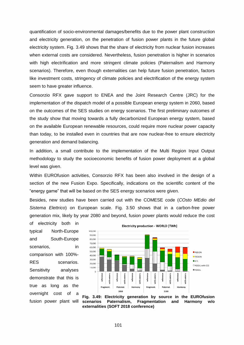
101
quantification of socio-environmental damages/benefits due to the power plant construction
and electricity generation, on the penetration of fusion power plants in the future global
electricity system. Fig. 3.49 shows that the share of electricity from nuclear fusion increases
when external costs are considered. Nevertheless, fusion penetration is higher in scenarios
with high electrification and more stringent climate policies (Paternalism and Harmony
scenarios). Therefore, even though externalities can help future fusion penetration, factors
like investment costs, stringency of climate policies and electrification of the energy system
seem to have greater influence.
Consorzio RFX gave support to ENEA and the Joint Research Centre (JRC) for the
implementation of the dispatch model of a possible European energy system in 2060, based
on the outcomes of the SES studies on energy scenarios. The first preliminary outcomes of
the study show that moving towards a fully decarbonized European energy system, based
on the available European renewable resources, could require more nuclear power capacity
than today, to be installed even in countries that are now nuclear-free to ensure electricity
generation and demand balancing.
In addition, a small contribute to the implementation of the Multi Region Input Output
methodology to study the socioeconomic benefits of fusion power deployment at a global
level was given.
Within EUROfusion activities, Consorzio RFX has been also involved in the design of a
section of the new Fusion Expo. Specifically, indications on the scientific content of the
“energy game” that will be based on the SES energy scenarios were given.
Besides, new studies have been carried out with the COMESE code (COsto MEdio del
Sistema Elettrico) on European scale. Fig. 3.50 shows that in a carbon-free power
generation mix, likely by year 2080 and beyond, fusion power plants would reduce the cost
of electricity both in
typical North-Europe
and South-Europe
scenarios, in
comparison with 100%-
RES scenarios.
Sensitivity analyses
demonstrate that this is
true as long as the
overnight cost of a
fusion power plant will
Fig. 3.49: Electricity generation by source in the EUROfusion scenarios Paternalism, Fragmentation and Harmony w/o
externalities (SOFT 2018 conference)

102
be lower than 8500 Eur/kW in the North-Europe case and lower than 12500 Eur/kW in the
South-Europe case. Studies on the economic impact of the electric grid expansion due to the
increased share of electricity from renewables have been postponed to 2019.
SES economic studies – dissemination and communication of results 3.5.3.
In 2018, dissemination and communication of the SES foresight activities started with the
upgrade of the SES pages of the EUROfusion website. In particular, larger emphasis was
put: a) on the presentation of the stakeholder consultation on storylines and scenarios
carried out through a Delphi survey, to give reason for the interesting results collected from
stakeholders’ opinion; b) on the illustration of the first data obtained from the European
Survey on public attitudes towards fusion energy and research carried out in 2018 by SES in
view of their analysis in 2019.
3.6. Education and Training
In 2017 the Universities of Padua and Gent, on the basis of the successful experience in
running two international leading programmes (the Padua-Lisbon-Munich and the Erasmus
Mundus Fusion Doctoral College), have implemented a Joint Doctorate Programme in
Fusion Science and Engineering aiming at the continued formation of a suitable number of
doctoral students at the highest level of excellence. So far, 8 PhD students have been
enrolled in academic year 2017/18 (XXIII cycle) and 2018/19 (XXIV cycle).
Moreover, in academic year 2016/17 10 PhD students enrolled in the last cohort(XXXII
cycle) of the previous Doctorate Programme in Fusion Science and Engineering,
coordinated by Padua University under an international agreement between the Universities
of Padua, Lisbon and Naples “Federico II”.
Fig. 3.50: Probability density distribution of the LCOTE generated with the COMESE code (SOFT 2018)

103
Overall, in 2019 18 PhD students will operate at Consorzio RFX and partners’ premises,
under the tutoring of members of the PhD Academic Council and RFX researchers.
The other educational and training actions carried out at Consorzio RFX have continued as
usual, with tutoring of 24 Master/Bachelor students in Physics or Engineering , with
internships of master students and with summer stages of high school students.
One master student in Physics has carried out a thesis project in the field of fusion at the
Eindhoven Technical University, under an Erasmus student exchange program coordinated
by the Physics and Astronomy Department of Padova University.
Moreover the following 7 regular courses on Plasma Physics, Fusion Technology and
Industrial Applications of Plasmas were held by teachers from Consorzio RFX at Padua
University:
Basic principles of Plasma Physics (6 ECTS, 1st Level Degree, Physics)
Physics of Nuclear Fusion and Applications of Plasmas (6 ECTS, 2nd Level Degree,
Physics)
Fluid and Plasmas Physics (6 ECTS, 2nd Level Degree, Physics)
Fission and Fusion Nuclear Plants (9 ECTS, 2nd Level Degree, Engineering)
Energy Technology and Economics (9 ECTS, 2nd Level Degree, Engineering)
In addition a national prize of the Consorzio RFX for the best thesis project in the field of
controlled fusion has been awarded to 4 master studentes, 2 in Physics and 2 in
Engineering.
3.7. Communication and outreach
The information activity carried out in 2018 at Consorzio RFX developed, in
collaboration with ITER IO and F4E communication offices and Eurofusion Public
Information network, along two main lines of activities:
production of information content;
outreach and communication initiatives;
Informative material (brochures and posters), multimedia content and production
(photos, videos) and press kits were regularly produced on the occasion of events
and initiatives, the most significant are listed below.
The first months of 2018 were dedicated to the preparation of the ceremony of
SPIDER Inauguration, which took place on 11 June 2018. Weekly video-conference
discussions among IO, F4E and RFX communicators were regularly organized to
agree on shared approaches and schedule of the event. About 360 people attended

104
the ceremony in the presence of ITER and its stakeholders. During the ceremony,
plasma was generated in the beam ion source for the first time and the event was
seen in streaming worldwide.
In order to prepare the Italian press to report on it and increase the media interest on fusion
research and ITER NBI research, a course for Italian journalists was held on 6 June 2018 at
NBTF premises in collaboration with the Order of the Journalists of the Veneto. The event
was attended by 26 journalists, some of them wrote articles covering the Spider event.
The preparation of the European Night of Researchers (28 September 2018) started soon
after, with the realization of an education game on the optimization of negative beam
production in SPIDER and with the organization of the exhibition at the University of Padua,
guided by a team of about 10 researchers from Consorzio RFX. Within the activities of the
European Night of Researchers, a promo video on SPIDER-NBTF was realized in parallel; it
was shown at Porto Astra Multiplex, a large cinema in Padova, before each shows in all the
movie theatres, free of charge, for a couple of weeks, thus reaching a large audience. An
evaluation of the feedback could not be taken from the audience, since no questionnaire
could be prepared in time; still really positive comments arrived from Porto Astra, who could
monitor the public reaction, and from personal contacts.
In August, Consorzio RFX presented the NBTF project at the 75 Mostra Internazionale di
Arte Cinematografica of Venice during an event organized by the Veneto Region at Hotel
Excelsior. The presentation focused on how fusion and plasma heating can be seen through
the video camera. The event sow the participation of industrialists and representatives of the
Veneto Region and of the author of some videos produced at Consorzio RFX. The event
was successful and led to a new interest from the Region towards the research.
During the summer, Topolino, the Italian version of the Walt Disney production, could finalize
the story "Topolino e il padrone del buio" ("Mickey Mouse and the owner of the dark"). It'll be
published and the beginning of 2019.
Two other important events were organized towards the end of the year: in late October
about 50 industrialists from the Salone di Impresa Organization visited the Consorzio RFX
laboratories; on 19 November the Urban Sketcher Claudio Patanè organized a workshop of
Science Sketching at Consorzio RFX in collaboration with Accatagliato Association, Observa
and the City of Padua.
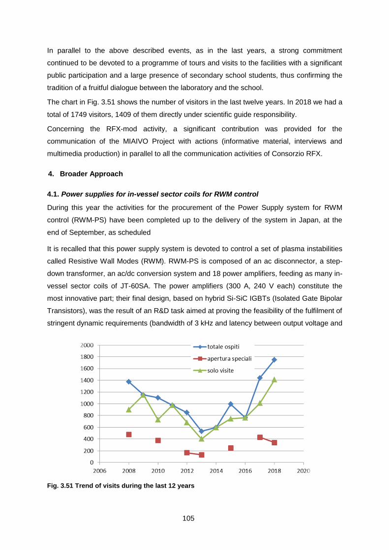
105
In parallel to the above described events, as in the last years, a strong commitment
continued to be devoted to a programme of tours and visits to the facilities with a significant
public participation and a large presence of secondary school students, thus confirming the
tradition of a fruitful dialogue between the laboratory and the school.
The chart in Fig. 3.51 shows the number of visitors in the last twelve years. In 2018 we had a
total of 1749 visitors, 1409 of them directly under scientific guide responsibility.
Concerning the RFX-mod activity, a significant contribution was provided for the
communication of the MIAIVO Project with actions (informative material, interviews and
multimedia production) in parallel to all the communication activities of Consorzio RFX.
Broader Approach 4.
4.1. Power supplies for in-vessel sector coils for RWM control
During this year the activities for the procurement of the Power Supply system for RWM
control (RWM-PS) have been completed up to the delivery of the system in Japan, at the
end of September, as scheduled
It is recalled that this power supply system is devoted to control a set of plasma instabilities
called Resistive Wall Modes (RWM). RWM-PS is composed of an ac disconnector, a step-
down transformer, an ac/dc conversion system and 18 power amplifiers, feeding as many in-
vessel sector coils of JT-60SA. The power amplifiers (300 A, 240 V each) constitute the
most innovative part; their final design, based on hybrid Si-SiC IGBTs (Isolated Gate Bipolar
Transistors), was the result of an R&D task aimed at proving the feasibility of the fulfilment of
stringent dynamic requirements (bandwidth of 3 kHz and latency between output voltage and
Fig. 3.51 Trend of visits during the last 12 years

106
reference lower than 50 s), which were beyond the standard industrial performances,
adopting a simple H-bridge topology.
The contract for the procurement of the whole system was placed at the beginning of 2016.
After the completion of the detailed design and the development and test of the prototype
completed in June 2017, the system manufacturing was completed this year, in late spring.
The factory tests and final integrated tests with the whole system, connected like in the final
conditions on Site, fully confirmed the expected performance. For each power amplifier
connected to the dummy load, the dynamic performance in terms of bandwith and latency
were verified; the test results confirmed the fullfilment of the requirements with significant
margin. Other key features were verified too, like the compensation of the non-linearities due
to the dead-time to be introduced in the power switches commands to prevent the
simultaneous conduction of two switches in the same leg of the fast inverter H-bridge, the
effectiveness of the differential output filter to reduce the resonances on the long output
cable, and of the common mode filter to smooth the Common Mode voltage oscillations at
the load. The correct operation of a dynamic voltage clamp circuit provided in parallel to the
dc-link so as to enhance the protection capability for the possible overvoltages induced in
case of plasma fast terminations, was also successfully verified. Fig. 4.1 shows the whole
RWM-PS system in the final test arrangement.
Fig. 4.1 - Arrangement of the whole RWM-PS system for the final integrated tests

107
Unfortunately, during the unpacking of the components in Naka, it has been realized that a
cabinet including 9 inverters (PCC-B) sustained severe damages during the transportation.
The reason and the time when the damages occurred are not yet been clarified. A
clarification process among the insurance companies (of the companies in charge fro the
packaging, the sea transportation and the ground transportation in Japan) is in progress.
Industrial and non-fusion related collaborations 5.
5.1. Electrostatic design of Vacuum Interrupters using the Voltage Holding Prediction
Model
In 2018 the activity has been almost stopped in absence of an official Agreement with
Siemens. Anyhow, in the last quarter of the year discussion with Siemens has taken place to
finalize the content of a new agreement. To this purpose, at the Dept. of Electrical
Engineering, Padova University a Lightning Impulse Voltage Waveform (LIVW) pulse
generator has been set up - see Fig. 5.1 - to perform preliminary tests on two samples of
Vacuum Interrupters sent by Siemens Berlin.
A new procedure of voltage application has been implemented, that proved to be more
effective in producing Weibull voltage breakdown distribution. The agreement is presently
under signature in Berlin
5.2. Biomedical plasma applications
As in previous years, a substantial effort has been devoted to the improvement of the array
of plasma sources available for the research on biomedical plasma applications. In the past,
all the activities were performed using a radiofrequency (RF) plasma source for indirect
Fig. 5.1 LIVW generator arranged to produce a 300 kV pulse. Inside the transparent tank is visible the VI under test. On the right, the voltage breakdown distribution (8 mm contact gap),
and its Weibull distribution fit
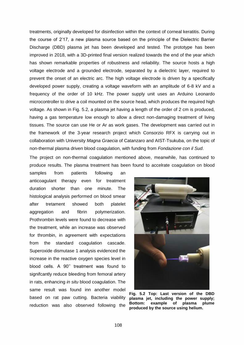
108
treatments, originally developed for disinfection within the context of corneal keratitis. During
the course of 2’17, a new plasma source based on the principle of the Dielectric Barrier
Discharge (DBD) plasma jet has been developed and tested. The prototype has been
improved in 2018, with a 3D-printed final version realized towards the end of the year which
has shown remarkable properties of robustness and reliability. The source hosts a high
voltage electrode and a grounded electrode, separated by a dielectric layer, required to
prevent the onset of an electric arc. The high voltage electrode is driven by a specifically
developed power supply, creating a voltage waveform with an amplitude of 6-8 kV and a
frequency of the order of 10 kHz. The power supply unit uses an Arduino Leonardo
microcontroller to drive a coil mounted on the source head, which produces the required high
voltage. As shown in Fig. 5.2, a plasma jet having a length of the order of 2 cm is produced,
having a gas temperature low enough to allow a direct non-damaging treatment of living
tissues. The source can use He or Ar as work gases. The development was carried out in
the framework of the 3-year research project which Consorzio RFX is carrying out in
collaboration with University Magna Graecia of Catanzaro and AIST-Tsukuba, on the topic of
non-thermal plasma driven blood coagulation, with funding from Fondazione con il Sud.
The project on non-thermal coagulation mentioned above, meanwhile, has continued to
produce results. The plasma treatment has been found to accelrate coagulation on blood
samples from patients following an
anticoagulant therapy even for treatment
duration shorter than one minute. The
histological analysis performed on blood smear
after tretament showed both platelet
aggregation and fibrin polymerization.
Prothrombin levels were found to decrease with
the treatment, while an increase was observed
for thrombin, in agreement with expectations
from the standard coagulation cascade.
Superoxide dismutase 1 analysis evidenced the
increase in the reactive oxygen species level in
blood cells. A 90’’ treatment was found to
signifcantly reduce bleeding from femoral artery
in rats, enhancing in situ blood coagulation. The
same result was found inn another model
based on rat paw cutting. Bacteria viability
reduction was also observed following the
Fig. 5.2 Top: Last version of the DBD plasma jet, including the power supply; Bottom: example of plasma plume
produced by the source using helium.

109
plasma treatment, confirming that coagulation induction is accompanyied by a sterlizing
effect.
Concerning the RF source developed at Consorzio RFX, a detailed characterization of the
physical and chemical properties of the produced plasma was carried out, with techniques
including electrical measurements, Schlieren imaging, emission spectroscopy and fomration
of reactive oxygen and nitrogen species in the liquid phase through water treatment. In
particular, the dissipated power over the plasma was evaluated to be 0.4 W, a plasma
density of 1020 m-3 and an electron temperature of 0.18 eV were evaluated. Rotational and
vibrational temperatures were derived from N2 and OH spectral lines. It was found that
rotational temperature is a good estimator of the translational one and the vibrational
temperature is consistent with the electron temperature. The total UV emission in the range
200–315 nm was estimated through an absolute calibration of the UV part of the spectrum,
and found to be below safety EU prescriptions for treatment times shorter than 6 min. The
study on the liquid phase indicates that OH radicals are formed very efficiently in treated
water and may thus be the prevailing species responsible for the observed effects in
previous applications.
The disinfectant effect of the RF source was also studied in detail. In particular, it was found
that the plasma treatment induces a membrane permeabilization in both the outer and inner
membrane of Gram-negative bacteria, and also a depolarization of the membrane. The
disrtuption of the cytoplasmic (inner) membrane prevents the generation of antibiotic-
resistant forms, as was demonstrated thrugh repeated exposure to the plasma effect.
Moreover, the plasma was found to synergistically cooperated with common antimicrobial
drugs to maximize antibacterial activity, likely by facilitating penetration of antimicrobial drugs
through damage of bacterial layers. The antibacterial activity was found to be independent of
the cell wall thickness and structure, thus confirming the plasma treatment as and effective
inactivation strategy for the treatment of polymicrobial infections in living tissues.
Details on the ongoing activities were communicated to the scientific community in invited
talks at the International Confernce on Plasma Medicine (ICPM-7) in Philadelphia, at the
ISPlasma conference in Nagoya and at the ISNTP-11 conference in Montegrotto Terme.
5.3. Plasma study for GALILEO Passive Hydrogen Maser
Anomalous operation is occasionally affecting the space Passive Hydrogen Maser (PHM),
the master clock on the Galileo navigation payload manufactured by Leonardo-
Finmeccanica and SpectraTime. This anomaly is attributed to malfunctioning of the
Hydrogen Dissociator, with reduced dissociation efficiency and consequent reduced flux of
atomic Hydrogen from the Dissociator to the Maser cavity. The physics of the Dissociator

110
has some important analogies with that of the RF source for ITER NBTF. In late 2017
Leonardo has signed a contract with Consorzio RFX and with Nanotech-Bari for a
characterization of the Dissociator, aiming at the identification of possible causes of
malfunctioning. The contact foresees three phase: preliminary joint analysis of the available
documentation, modeling the Dissociator by Nanotech, experimental investigation of an
available module using spectroscopic techniques by Consorzio RFX. In 2018 the first phase
has been completed. Consorzio RFX has prepared and actively contributed to a failure
investigation review meeting with Leonardo, ESA and other project parties and eventually
produced a report with the analysis of available measurements and a literature survey
relevant to the understanding of the dissociator operation and possible
failure routes: capacitive-to-inductive coupling hysteresis and the hyodroxylation kinetics on
the bulb surface were considered the most relevant candidates and will therefore constitute
the focus of the simulation.