acoustic performance – case studies · 2018-04-13 · 1 building physics – acoustic performance...
TRANSCRIPT

Building Physics – Acoustic Performance
Acoustic Performance – Case Studies
Acoustic Performance of Steel in Residential Buildings Different forms of steel construction are commonly used for residential developments where good acoustic performance is required. The benefits of steel construction, including speed, quality and off-site prefabrication, are important to meeting the demands of construction for modern residential buildings, often on confined urban or brownfield sites. The Building Regulations and Approved Document E set minimum standards of acoustic performance for the walls and floors in multi occupancy residential developments. The SCI has published several design guides on the acoustic detailing of steel buildings. However, the following eight case studies reinforce the guidance given in those publications by providing actual acoustic test data from developments using steel construction of various forms.
Project sponsored by:
Case Study 1: The Waterfront, Grantham: Steel frame with composite floors
Case Study 2: St Peters Court, Bristol: Steel frame with precast floors
Case Study 3: The Paragon Project, London: High rise modular construction
Case Study 4: Light steel floors with Gyvlon screed
Case Study 5: Zero4, Plymouth: Hot-rolled steel frame with Slimdek floors
Case Study 6: Basingstoke: Modular steel frame construction
Case Study 7: Riverview, Hereford: Hot-rolled steel frame with composite fibre-reinforced slab floors
Case Study 8: Brightwell Court and Minerva Lodge, London: Fusion light steel structural framing SCI P371

1
Building Physics – Acoustic Performance
Acoustic Performance – Case Study 1
The Waterfront, Grantham: Steel Frame with Composite Floors
The Waterfront is a major new residential complex developed by Urban Residential Development and Investment Ltd (URDI) in Grantham town centre. The building has been constructed using a hot-rolled steel frame with composite beams, composite floor slabs using metal decking and light steel infill walls.
The structural frame has conventional Universal Beam and Universal Column sections. The composite floor is a 175 mm slab on 60 mm deep trapezoidal metal decking with normal weight concrete. The acoustic performance of the floor is achieved by the mass of the slab combined with a platform floor treatment above and a suspended ceiling below.
The infill walls are only 150 mm thick consisting of light steel studs with resilient bars on one side, insulation between the studs and both sides of the wall lined with two layers of sound resistant plasterboard.
A hot-rolled steel frame was chosen for the development because of the speed of construction and because a steel frame was predicted to be less expensive than a concrete frame structure. The structural steelwork was erected in just six weeks.
The acoustic performance of the floors has substantially exceeded The Building Regulation requirements, by an average of 10 dB for airborne sound and by an average of 19 dB for impact sound. The walls also easily satisfy the acoustic performance standards required by the Building Regulations[1] and Approved Document E[2].
Acoustic performance summary
Element Sound reduction Measured Required
Floor Airborne 55 dB ≥ 45 dB
Floor Impact 43 dB ≤ 62 dB
Wall Airborne 49 dB ≥ 45 dB
A G J Way
MEng CEng MICE
Car park below apartments
Composite deck on steel beams
Project sponsored by:

2
Acoustic Performance: The Waterfront, Grantham
Floor and wall details
The detailed construction of the separating floor and wall are illustrated and summarised below. Acoustic enhancement of the floor was generally provided by a platform floor treatment and a suspended ceiling. In some locations within the development, an isolated screed was used as the floor treatment.
For highly serviced areas such as kitchens, a service void was constructed by an additional layer of gypsum-based board (as shown below) to ensure the acoustic integrity of the separating wall is not compromised by service penetrations.
12.5
25
18
Metal frame for ceiling
25 mm thick dense mineral woolresilient layer
18 mm thick tongue and groove chipboardwalking surface
Normal weight concrete(min. 2200 kg/m²)
175
Trapezoidal deck(60 mm deep) Single layer of 12.5 mm thick
plasterboard suspended ceiling
Separating floor: • 18 mm tongue and groove
chipboard • 25 mm of dense mineral wool • 175 mm composite floor slab
on shallow trapezoidal decking (60 mm deep) with normal weight concrete
• 12.5 mm plasterboard ceiling (nominal 8 kg/m2) supported on proprietary metal frame.
Separating wall construction
Service void on surface of separating wall
Timber or light steel stud
Electrical socketor switch etc.
One layer of gypsum-basedboard
Service void detail in separating wall
Separating wall:
• Two layers of 15 mm sound resistant plasterboard
• Horizontal resilient bar spaced a 600 mm centres
• 70 mm light steel stud section
• 50 mm of mineral wool insulation between studs
• Two layers of 15 mm sound resistant plasterboard
Elevation of the Waterfront Development

3
Acoustic testing
On-site acoustic testing was carried out in accordance with BS EN ISO 140: Part 4[3] for the airborne sound and BS EN ISO 140: Part 7[4] for the impact sound. The Standard Weighted Level Difference DnT,w , the Standard Weighted Impact Sound Pressure Level L’nT,w , and the spectrum adaptation term Ctr were calculated in accordance with BS EN ISO 717[5]. The measured results for the acoustic performance of the separating floors and walls are shown in Table 1 and Table 2, respectively.
Table 1: On-site acoustic test results for floors
Floor test results Measured Building
Regulations
Test 1 56 dB ≥ 45 dB
Test 2 57 dB ≥ 45 dB
Test 3 60 dB ≥ 45 dB
Test 4 54 dB ≥ 45 dB
Test 5 50 dB ≥ 45 dB
Test 6 49 dB ≥ 45 dB
Test 7 57 dB ≥ 45 dB
Test 8 59 dB ≥ 45 dB
Airborne
(DnT,w + Ctr)
Average 55 dB ≥ 45 dB
Test 1 44 dB ≤ 62 dB
Test 2 42 dB ≤ 62 dB
Test 3 41 dB ≤ 62 dB
Test 4 45 dB ≤ 62 dB
Test 5 44 dB ≤ 62 dB
Test 6 46 dB ≤ 62 dB
Test 7 36 dB ≤ 62 dB
Test 8 42 dB ≤ 62 dB
Impact
(L’nT,w)
Average 43 dB ≤ 62 dB
Table 2: On-site acoustic test results for walls
Wall test results Measured Building
Regulations
Test 1 49 dB ≥ 45 dB
Test 2 50 dB ≥ 45 dB
Test 3 48 dB ≥ 45 dB
Test 4 48 dB ≥ 45 dB
Test 5 47 dB ≥ 45 dB
Test 6 48 dB ≥ 45 dB
Test 7 49 dB ≥ 45 dB
Test 8 51 dB ≥ 45 dB
Airborne (DnT,w + Ctr)
Average 49 dB ≥ 45 dB
The test results show that the requirements of the Building Regulations for separating walls and floors were easily satisfied.
The tests were carried out from April to July 2007 by the Building Test Centre. The tests were commissioned by The Steel Construction Institute as part of their on-going programme of acoustic data collection for steel framed building. The results were used towards pre-completion testing (PCT) to demonstrate Building Regulations compliance for Building Control.
Junction details
High density compressed board
Two layers of gypsum-based board Unfaced mineral wool
Floor insulationAcoustic sealantResilient flanking strip
Resilient bar, one side
1 layer of 12.5 mm plywood
Mineral wool packing
Acoustic sealant
Shallow decking
Metal frame ceiling hanger
Metal frame for ceiling
One layer of gypsum-basedboard nominal 8 kg/m²
Junction detail between separating floor and separating wall
Junction details used in the project are shown in the two figures opposite and below. These details are carefully designed to minimise the transmission of flanking sound at the wall and floor junctions.
4
Acoustic Performance: The Waterfront, Grantham
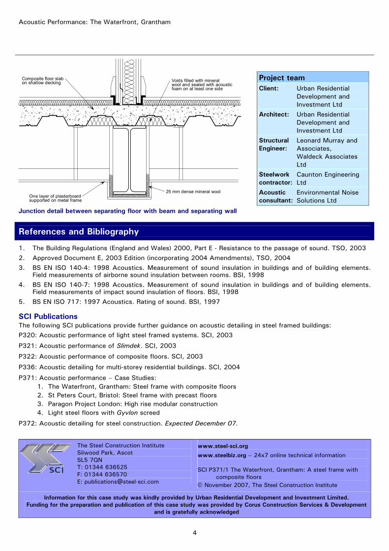
One layer of plasterboardsupported on metal frame
Composite floor slabon shallow decking
25 mm dense mineral wool
Voids filled with mineralwool and sealed with acousticfoam on at least one side
Junction detail between separating floor with beam and separating wall
Project team Client: Urban Residential
Development and Investment Ltd
Architect: Urban Residential Development and Investment Ltd
Structural Engineer:
Leonard Murray and Associates, Waldeck Associates Ltd
Steelwork contractor:
Caunton Engineering Ltd
Acoustic consultant:
Environmental Noise Solutions Ltd
References and Bibliography
1. The Building Regulations (England and Wales) 2000, Part E - Resistance to the passage of sound. TSO, 2003 2. Approved Document E, 2003 Edition (incorporating 2004 Amendments), TSO, 2004 3. BS EN ISO 140-4: 1998 Acoustics. Measurement of sound insulation in buildings and of building elements.
Field measurements of airborne sound insulation between rooms. BSI, 1998 4. BS EN ISO 140-7: 1998 Acoustics. Measurement of sound insulation in buildings and of building elements.
Field measurements of impact sound insulation of floors. BSI, 1998 5. BS EN ISO 717: 1997 Acoustics. Rating of sound. BSI, 1997
SCI Publications The following SCI publications provide further guidance on acoustic detailing in steel framed buildings: P320: Acoustic performance of light steel framed systems. SCI, 2003
P321: Acoustic performance of Slimdek. SCI, 2003
P322: Acoustic performance of composite floors. SCI, 2003
P336: Acoustic detailing for multi-storey residential buildings. SCI, 2004
P371: Acoustic performance – Case Studies: 1. The Waterfront, Grantham: Steel frame with composite floors 2. St Peters Court, Bristol: Steel frame with precast floors 3. Paragon Project London: High rise modular construction 4. Light steel floors with Gyvlon screed
P372: Acoustic detailing for steel construction. Expected December 07.
The Steel Construction Institute
Silwood Park, Ascot SL5 7QN T: 01344 636525 F: 01344 636570 E: [email protected]
www.steel-sci.org
www.steelbiz.org – 24x7 online technical information SCI P371/1 The Waterfront, Grantham: A steel frame with
composite floors © November 2007, The Steel Construction Institute
Information for this case study was kindly provided by Urban Residential Development and Investment Limited. Funding for the preparation and publication of this case study was provided by Corus Construction Services & Development
and is gratefully acknowledged

1
Building Physics – Acoustic Performance
Acoustic Performance – Case Study 2
St Peters Court, Bristol: Steel Frame with Precast Floors
St Peters Court is a £13 million mixed use development in Bristol’s Bedminster area, comprising 86 residential units, a health centre, offices, library, and conversion of an existing Grade II listed Police Station building into a public house and restaurant. PG Enterprises Limited formed a partnership with Bristol City Council Library Services to acquire the rights to develop the adjacent site which includes a Grade II listed building housing the Bedminster library. The existing library has been relocated and the vacated building has been refurbished to establish a ground floor art gallery with offices above.
The construction of the development is mainly a hot-rolled steel frame with Bison precast concrete floor units. The separating floors have a Gyvlon screed which is isolated from the precast units by a foam layer and a layer of dense mineral wool. A suspended plasterboard ceiling is also provided. Gyvlon is a pump grade liquid gypsum screed developed by Lafarge Plasterboard Limited. The screed provides a flat level surface and has excellent acoustic properties. The separating walls between dwellings are of light steel stud construction. Twin stud frames are constructed with a cavity between them which is filled with glass wool insulation. The faces of the walls are lined with two layers of sound resistant plasterboard.
The acoustic performance of the floors has significantly exceeded The Building Regulation[1] and Approved Document E[2] requirements by 9 dB for airborne sound and 15 dB for impact sound. The walls also easily satisfy the minimum standards set by The Building regulations by 7 dB
Acoustic performance summary
Element Sound reduction Measured Required
Floor Airborne 54 dB ≥ 45 dB
Floor Impact 47 dB ≤ 62 dB
Wall Airborne 52 dB ≥ 45 dB
A G J Way
MEng CEng MICE
Bracing details
Hollow core units on steel frame
Project sponsored by:

2
Acoustic Performance: St Peters Court Bristol
Floor and wall details
The detailed construction of the separating floors and walls are illustrated and summarised below. The acoustic performance of the floor is achieved by the combination of a suspended ceiling, hollow core precast floor units and a Gyvlon screed isolated from the precast floor units.
The walls rely on separate light steel stud walls, insulation and two layers of sound resistance plasterboard on each side for its acoustic performance.
Section 4.3 of SCI publication P351[6] provides guidance on the acoustic detailing of precast floors in steel framed buildings.
Separating floor:
• 40 mm Gyvlon screed • 5 mm resilient foam layer • 25 mm dense mineral fibre • 200 mm hollow core precast concrete unit
(300 kg/m3) • 100 mm cavity • 12.5 mm sound resistant plasterboard ceiling
supported on proprietary metal frame.
Separating floor construction
Separating wall:
• Two layers of 15 mm sound resistant plasterboard • 50 mm light steel C section stud frame • 50 mm glass mineral wool (24 kg/m3) in cavity
between twin stud frames • 50 mm light steel C section stud frame • Two layers of 15 mm sound resistant plasterboard.
Separating wall construction
Curved roof detail
Steel balconies
Bathroom BathroomKitchen
Living room Living roomBedroom Bedroom Bedroom
Kitchen
Cup'd Cup'd
Typical layout of apartments at St Peters Court
3
Acoustic testing
On-site acoustic testing was carried out in accordance with BS EN ISO 140: Part 4[3] for the airborne sound and BS EN ISO 140: Part 7[4] for the impact sound. The Standard Weighted Level Difference DnT,w , the Standard Weighted Impact Sound Pressure Level L’nT,w , and the spectrum adaptation term Ctr were calculated in accordance with BS EN ISO 717[5]. The measured results for the acoustic performance of the separating floors and walls are shown in Table 1 and Table 2, respectively. Table 1: On-site acoustic test results for floors
Floor test results Measured Building
Regulations
Test 1 54 dB ≥ 45 dB
Test 2 51 dB ≥ 45 dB
Test 3 54 dB ≥ 45 dB
Test 4 55 dB ≥ 45 dB
Test 5 54 dB ≥ 45 dB
Test 6 54 dB ≥ 45 dB
Test 7 52 dB ≥ 45 dB
Test 8 56 dB ≥ 45 dB
Airborne
(DnT,w + Ctr)
Average 54 dB ≥ 45 dB
Test 1 49 dB ≤ 62 dB
Test 2 48 dB ≤ 62 dB
Test 3 43 dB ≤ 62 dB
Test 4 47 dB ≤ 62 dB
Test 5 47 dB ≤ 62 dB
Test 6 47 dB ≤ 62 dB
Test 7 47 dB ≤ 62 dB
Test 8 47 dB ≤ 62 dB
Impact
(L’nT,w)
Average 47 dB ≤ 62 dB
Table 2: On-site acoustic test results for walls
Wall test results Measured Building
Regulations
Test 1 54 dB ≥ 45 dB
Test 2 53 dB ≥ 45 dB
Test 3 51 dB ≥ 45 dB
Test 4 51 dB ≥ 45 dB
Test 5 53 dB ≥ 45 dB
Test 6 51 dB ≥ 45 dB
Test 7 55 dB ≥ 45 dB
Test 8 50 dB ≥ 45 dB
Airborne (DnT,w + Ctr)
Average 52 dB ≥ 45 dB
The results show that the floor and wall constructions used to separate the apartments have acoustic performance well in excess of that required by the Building Regulations. The level of acoustic performance which was achieved exceeds the requirements of Robust Details.
The tests were carried out by Philip Dunbavin Acoustics Ltd and Noise.co.uk Ltd.
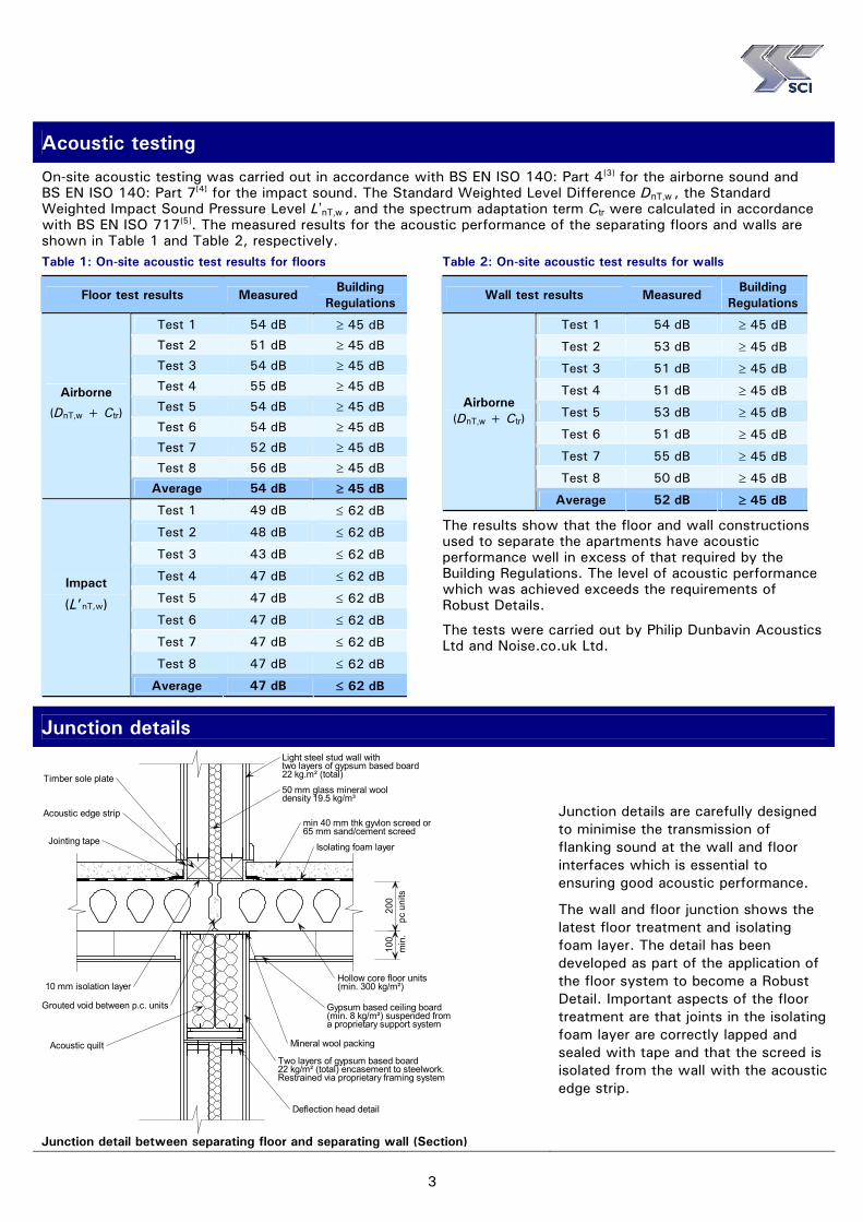
Junction details
min 40 mm thk gyvlon screed or65 mm sand/cement screed
Isolating foam layer
200
100
pc u
nits
min
.
Hollow core floor units(min. 300 kg/m²)
50 mm glass mineral wooldensity 19.5 kg/m³
Light steel stud wall withtwo layers of gypsum based board22 kg.m² (total)
Acoustic edge strip
Timber sole plate
Jointing tape
Grouted void between p.c. units
Acoustic quiltTwo layers of gypsum based board22 kg/m² (total) encasement to steelwork. Restrained via proprietary framing system
Gypsum based ceiling board(min. 8 kg/m²) suspended froma proprietary support system
Deflection head detail
Mineral wool packing
10 mm isolation layer
Junction detail between separating floor and separating wall (Section)
Junction details are carefully designed to minimise the transmission of flanking sound at the wall and floor interfaces which is essential to ensuring good acoustic performance.
The wall and floor junction shows the latest floor treatment and isolating foam layer. The detail has been developed as part of the application of the floor system to become a Robust Detail. Important aspects of the floor treatment are that joints in the isolating foam layer are correctly lapped and sealed with tape and that the screed is isolated from the wall with the acoustic edge strip.
4
Acoustic Performance: St Peters Court, Bristol
External wallBreather membrane
Cavity barrier
Lafarge acoustic sealant
Abutment studs onRAFT50 resilient tape
Lafarge thermalsheathing
Lafarge 12.5 mmVapourcheck wallboard
Lafarge 12.5 mm Firecheck wall board
Junction detail between external wall and separating wall (Plan)
Project team Client: PG Enterprises Ltd
Architect: Atkins Walter &
Webster Structural Engineer:
Hastings Clements & Leech
Precast supplier:
Bison Concrete Products Ltd
Steelwork contractor:
Kier Western
Acoustic consultant:
Philip Dunbavin Acoustics Ltd
References and Bibliography
1. The Building Regulations (England and Wales) 2000, Part E - Resistance to the passage of sound. TSO, 2003 2. Approved Document E, 2003 Edition (incorporating 2004 Amendments), The Stationary Office, 2004 3. BS EN ISO 140-4: 1998 Acoustics. Measurement of sound insulation in buildings and of building elements.
Field measurements of airborne sound insulation between rooms. BSI, 1998 4. BS EN ISO 140-7: 1998 Acoustics. Measurement of sound insulation in buildings and of building elements.
Field measurements of impact sound insulation of floors. BSI, 1998 5. BS EN ISO 717: 1997 Acoustics. Rating of sound. BSI, 1997 6. Precast concrete floors in steel framed buildings (P351). SCI, 2006
SCI Publications The following SCI publications provide further guidance on acoustic detailing in steel framed buildings: P320: Acoustic performance of light steel framed systems. SCI, 2003 P321: Acoustic performance of Slimdek. SCI, 2003 P322: Acoustic performance of composite floors. SCI, 2003 P336: Acoustic detailing for multi-storey residential buildings. SCI, 2004 P371: Acoustic performance – Case Studies:
1. The Waterfront, Grantham: Steel frame with composite floors 2. St Peters Court, Bristol: Steel frame with precast floors 3. Paragon Project London: High rise modular construction 4. Light steel floors with Gyvlon screed
P372: Acoustic detailing for steel construction. Expected Dec 07
The Steel Construction Institute
Silwood Park, Ascot SL5 7QN T: 01344 636525 F: 01344 636370 E: [email protected]
www.steel-sci.org
www.steelbiz.org – 24x7 online technical information SCI P371/2 St Peters Court, Bristol: A steel frame with
precast floors © November 2007, The Steel Construction Institute
Information for this case study was kindly provided by Bison Concrete Products Limited. Funding for the preparation and publication of this case study was provided by Corus Construction Services & Development
and is gratefully acknowledged

1
Building Physics – Acoustic Performance
Acoustic Performance – Case Study 3
The Paragon Project, London: High Rise Modular Construction
The Paragon project in West London is Europe’s tallest modular structure. It comprises of five separate buildings, ranging in height from four to 17 storeys providing accommodation for over 1000 key workers and students within an urban environment.
The site has been developed by Berkeley First in conjunction with Thames Valley University. It is a mixed tenure project consisting of flats for purchase, flats for rent and student bedrooms. Modules for the Paragon project, supplied by Caledonian Building Systems, are a hybrid of hot-rolled and light steel sections. The frames of the modules are created from hot-rolled steel with fully welded connections and light steel is used for the floor and ceiling joists and wall studs. The modules were fitted out as complete rooms, including plumbing, wiring, full completion of en-suites, decorations and furniture fitting, prior to delivery and erection on site.
Stability is provided by concrete shear walls in the circulation cores for the taller blocks but all vertical forces are transferred to ground level directly through the modules themselves. The ability to design modular units to support the loadings of the tall structures without a secondary frame was a key in achieving both the programme and cost requirements of the Paragon project.
A summary of the acoustic test results for Block A of the Paragon project which provides key worker accommodation are shown below. The acoustic details were value engineered to comply with the Building Regulation[1] and the Approved Document E[2] requirements for rooms for residential purposes.
Acoustic performance summary
Element Sound reduction Measured Required
Floor Airborne 48 dB ≥ 45 dB
Floor Impact 54 dB ≤ 62 dB
Wall Airborne 47 dB ≥ 45 dB
A G J Way
MEng CEng MICE
Ariel view of Paragon project
Cladding detail of Block A
Project sponsored by:
2
Acoustic Performance: The Paragon Project, London
Construction details
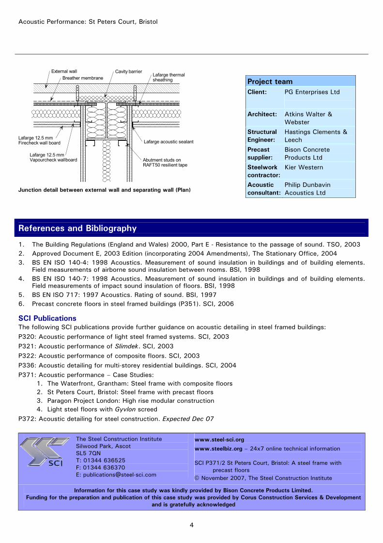
The vertical posts of the module frames are Square and Rectangular Hollow Sections with hot-rolled channels and Universal Beam section used for the horizontal elements. A typical module size is 12 m x 2.8 m, but some modules are manufactured up to 4.2 m wide, which achieved the required internal space planning and is the maximum for motorway transport. The steel frame allows for design flexibility, with angled modules and panel sections capable of being incorporated alongside the more typical rectangular modules.
Over 800 modules were used in the project, over 400 of which were in the 17 storey building. Sandwiched between the M4, suburban housing and a local school, the site presented major difficulties for access, delivery, storage of materials and site facilities for workers and equipment. Modular construction solved many of these problems, being essentially an off-site technology. Modules were delivered at an average rate of 8 per day and were installed in a 40 minute turn-around without requiring closure of roads.
Parallel flangechannel edge beams
Rectangular hollowsection columns
Light steel floor joists
Steel elements of a standard module prior to fit-out
Lifting an open-sided module
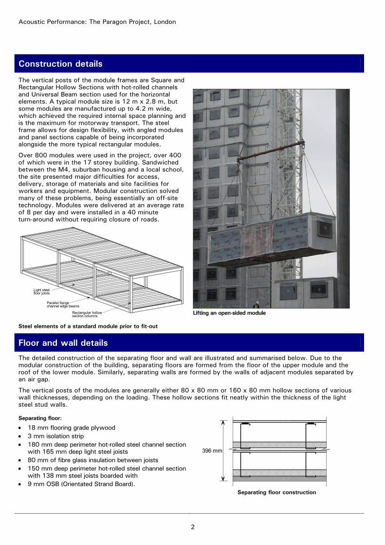
Floor and wall details
The detailed construction of the separating floor and wall are illustrated and summarised below. Due to the modular construction of the building, separating floors are formed from the floor of the upper module and the roof of the lower module. Similarly, separating walls are formed by the walls of adjacent modules separated by an air gap.
The vertical posts of the modules are generally either 80 x 80 mm or 160 x 80 mm hollow sections of various wall thicknesses, depending on the loading. These hollow sections fit neatly within the thickness of the light steel stud walls.
Separating floor:
• 18 mm flooring grade plywood • 3 mm isolation strip • 180 mm deep perimeter hot-rolled steel channel section
with 165 mm deep light steel joists • 80 mm of fibre glass insulation between joists • 150 mm deep perimeter hot-rolled steel channel section
with 138 mm steel joists boarded with • 9 mm OSB (Orientated Strand Board).
396 mm
Separating floor construction
3
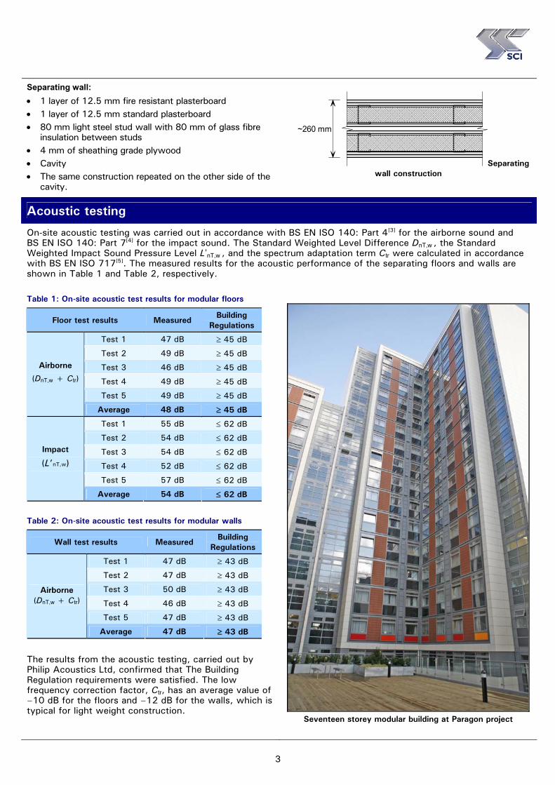
Separating wall: • 1 layer of 12.5 mm fire resistant plasterboard • 1 layer of 12.5 mm standard plasterboard • 80 mm light steel stud wall with 80 mm of glass fibre
insulation between studs • 4 mm of sheathing grade plywood • Cavity • The same construction repeated on the other side of the
cavity.
~260 mm
Separating wall construction
Acoustic testing
On-site acoustic testing was carried out in accordance with BS EN ISO 140: Part 4[3] for the airborne sound and BS EN ISO 140: Part 7[4] for the impact sound. The Standard Weighted Level Difference DnT,w , the Standard Weighted Impact Sound Pressure Level L’nT,w , and the spectrum adaptation term Ctr were calculated in accordance with BS EN ISO 717[5]. The measured results for the acoustic performance of the separating floors and walls are shown in Table 1 and Table 2, respectively.
Table 1: On-site acoustic test results for modular floors
Floor test results Measured Building
Regulations
Test 1 47 dB ≥ 45 dB
Test 2 49 dB ≥ 45 dB
Test 3 46 dB ≥ 45 dB
Test 4 49 dB ≥ 45 dB
Test 5 49 dB ≥ 45 dB
Airborne
(DnT,w + Ctr)
Average 48 dB ≥ 45 dB
Test 1 55 dB ≤ 62 dB
Test 2 54 dB ≤ 62 dB
Test 3 54 dB ≤ 62 dB
Test 4 52 dB ≤ 62 dB
Test 5 57 dB ≤ 62 dB
Impact
(L’nT,w)
Average 54 dB ≤ 62 dB
Table 2: On-site acoustic test results for modular walls
Wall test results Measured Building
Regulations
Test 1 47 dB ≥ 43 dB
Test 2 47 dB ≥ 43 dB
Test 3 50 dB ≥ 43 dB
Test 4 46 dB ≥ 43 dB
Test 5 47 dB ≥ 43 dB
Airborne (DnT,w + Ctr)
Average 47 dB ≥ 43 dB
The results from the acoustic testing, carried out by Philip Acoustics Ltd, confirmed that The Building Regulation requirements were satisfied. The low frequency correction factor, Ctr, has an average value of –10 dB for the floors and –12 dB for the walls, which is typical for light weight construction.
Seventeen storey modular building at Paragon project

4
Acoustic Performance: The Paragon Project, London
Junction details
As for all types of construction, the junction details between modules and between walls and floors need careful detailing to ensure the acoustic performance is maintained by minimising the transfer of flanking sound. In modular construction, walls of two adjacent modules combine to create a separating wall and at the edge of the building the orthogonal walls of the module form the internal leaf of the external wall. In the Caledonian Building System modules, hollow section posts of the module fit neatly within the thickness of the light steel stud walls. The modular system can support a range of claddings and external finishes. Block A, a 4-storey building consisting of 48 modules was completed well in advance of the other phases and demonstrated the visual detail of the façades using lightweight insulated render and clay tiles.
Bathroom Bathroom
Bathroom
Kitchen Kitchen
Kitchen
Cup'd
Cup'd
Cup'd
Studio room Studio room Studio room
Typical layout of studio rooms in Block A
References and bibliography
1. The Building Regulations (England and Wales) 2000, Part E - Resistance to the passage of sound. TSO, 2003 2. Approved Document E, 2003 Edition (incorporating 2004 Amendments), TSO, 2004 3. BS EN ISO 140-4: 1998 Acoustics. Measurement of sound insulation in buildings and of building elements.
Field measurements of airborne sound insulation between rooms. BSI, 1998 4. BS EN ISO 140-7: 1998 Acoustics. Measurement of sound insulation in buildings and of building elements.
Field measurements of impact sound insulation of floors. BSI, 1998 5. BS EN ISO 717: 1997 Acoustics. Rating of sound. BSI, 1997 6. Precast concrete floors in steel framed buildings (P351). SCI, 2006
SCI Publications The following SCI publications provide further guidance on acoustic detailing in steel framed buildings:
P320: Acoustic performance of light steel framed systems. SCI, 2003
P321: Acoustic performance of Slimdek. SCI, 2003
P322: Acoustic performance of composite floors. SCI, 2003
P336: Acoustic detailing for multi-storey residential buildings. SCI, 2004
P371: Acoustic performance – Case Studies: 1. The Waterfront, Grantham: Steel frame with composite floors 2. St Peters Court, Bristol: Steel frame with precast floors 3. Paragon Project London: High rise modular construction 4. Light steel floors with Gyvlon screed
P372: Acoustic detailing for steel construction. Expected Dec 07
Project team Client: Berkeley First
Architect: Carey Jones Architects
Structural engineer:
Capita Symonds
Module contractor:
Caledonian Building Systems Ltd
Structural engineer (modules):
Alan Wood and Partners
Acoustic consultant:
Capita Symonds
The Steel Construction Institute Silwood Park, Ascot SL5 7QN T: 01344 636525 F: 01344 636370 E: [email protected]
www.steel-sci.org
www.steelbiz.org – 24x7 online technical information SCI P371/3 The Paragon project, London: High rise modular
construction © November 2007, The Steel Construction Institute
Information and images for this case study were kindly provided by Caledonian Building Systems Ltd. Funding for the preparation and publication of this case study was provided by Corus Construction Services & Development
and is gratefully acknowledged

1
Building Physics – Acoustic Performance
Acoustic Performance – Case Study 4
Light Steel Floors with Gyvlon Screed
King Edward Court occupies the prestigious site next to the Royal Station at Windsor and has been completely re-built to create a spacious public concourse and shopping area. The 5th to 8th floors on the street-side are the location of a new Travelodge hotel and are constructed entirely in light steel framing. The 4-storey building uses braced light steel cross-walls, comprising 100 x 1.6 mm C sections, at 3.8 m spacing and in some cases up to 5.9 m spacing. The flooring system is 350 mm deep and comprises light steel lattice joists, shallow steel decking and a Gyvlon screed. The façade uses insulated render on cement particle board that is screw fixed to the light steel framework.
The same technology has been used on projects in Middlesbrough and Brighton for 3- and 5-storey residential buildings. The motivation for using a Gyvlon screed floor was improved stiffness (reduced deflection), enhanced acoustic performance and a reduced self weight in comparison to a reinforced concrete alternative. Gyvlon is the trade name for a self-levelling synthetic anhydrite screed from Lafarge Plasterboard Limited. Metek UK Limited has pioneered the use of Gyvlon by combining it with light steel lattice floor joists. This unique combination of material technologies is specific to Metek and Lafarge.
The enhanced acoustic performance of the system was proven by on-site testing carried out at the first residential project in Brighton. The average acoustic performance of the floors exceeded The Building Regulation[1] [2] requirements by 6 dB for airborne sound and by 8 dB for impact sound.
Acoustic performance summary
Element Sound reduction Measured Required
Floor Airborne 51 dB ≥ 45 dB
Floor Impact 54 dB ≤ 62 dB
A G J Way MEng CEng MICE
R M Lawson BSc PhD CEng MICE
MIStructE MASCE ACGI
King Edward Court, Windsor
Light steel framing system
Broomlands, Middlesbrough
Project sponsored by:
2
Acoustic Performance: Gyvlon Screed System, used with light steel frames
Floor and wall details
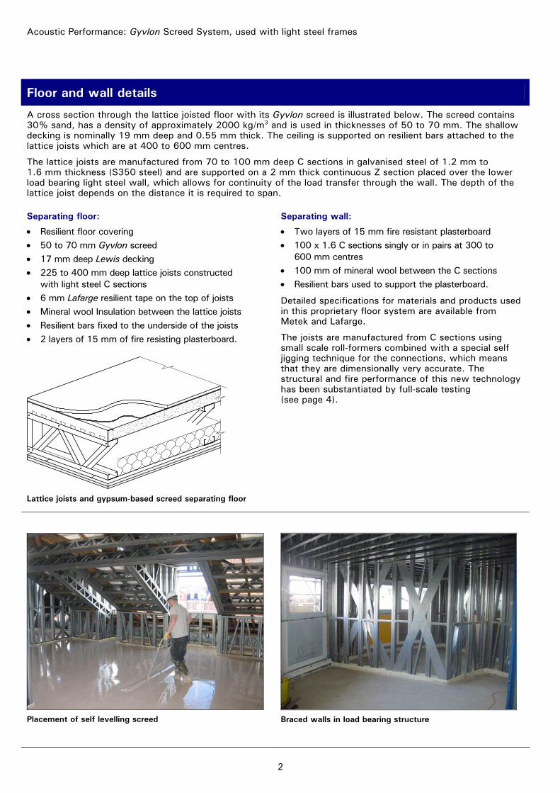
A cross section through the lattice joisted floor with its Gyvlon screed is illustrated below. The screed contains 30% sand, has a density of approximately 2000 kg/m3 and is used in thicknesses of 50 to 70 mm. The shallow decking is nominally 19 mm deep and 0.55 mm thick. The ceiling is supported on resilient bars attached to the lattice joists which are at 400 to 600 mm centres.
The lattice joists are manufactured from 70 to 100 mm deep C sections in galvanised steel of 1.2 mm to 1.6 mm thickness (S350 steel) and are supported on a 2 mm thick continuous Z section placed over the lower load bearing light steel wall, which allows for continuity of the load transfer through the wall. The depth of the lattice joist depends on the distance it is required to span.
Separating floor:
• Resilient floor covering • 50 to 70 mm Gyvlon screed • 17 mm deep Lewis decking • 225 to 400 mm deep lattice joists constructed
with light steel C sections • 6 mm Lafarge resilient tape on the top of joists • Mineral wool Insulation between the lattice joists • Resilient bars fixed to the underside of the joists • 2 layers of 15 mm of fire resisting plasterboard.
Lattice joists and gypsum-based screed separating floor
Separating wall:
• Two layers of 15 mm fire resistant plasterboard • 100 x 1.6 C sections singly or in pairs at 300 to
600 mm centres • 100 mm of mineral wool between the C sections • Resilient bars used to support the plasterboard.
Detailed specifications for materials and products used in this proprietary floor system are available from Metek and Lafarge.
The joists are manufactured from C sections using small scale roll-formers combined with a special self jigging technique for the connections, which means that they are dimensionally very accurate. The structural and fire performance of this new technology has been substantiated by full-scale testing (see page 4).
Placement of self levelling screed
Braced walls in load bearing structure
3
Acoustic testing
Laboratory acoustic tests carried out by Lafarge gave excellent results, and the first project in Brighton gave an opportunity to confirm these results by on-site tests. The acoustic test results are presented in Table 1.
On-site acoustic testing was carried out in accordance with BS EN ISO 140: Part 4[3] for the airborne sound and BS EN ISO 140: Part 7[4] for the impact sound. The Standard Weighted Level Difference DnT,w , the Standard Weighted Impact Sound Pressure Level L’nT,w , and the spectrum adaptation term Ctr were calculated in accordance with BS EN ISO 717[5].
The layers of the floor construction for the site tests are listed below (from top down): • Resilient floor covering • Gyvlon screed 65 mm deep including 16 mm deep decking • Light steel joists 225 mm deep placed at 600 mm centres - constructed from 65 × 1.2 mm C sections • 6 mm Lafarge resilient tape on top of joists • Mineral wool batts 100 mm thick placed between the lattice joists • Lafarge resilient bar fixed to the lattice joists • Lafarge Soundbloc plasterboard in two 15 mm layers.
The floor construction for the laboratory test was the same except there was no resilient floor covering and the Gyvlon was only a 50 mm deep (not 65 mm). These two differences would be expected to affect the results for impact sound significantly. The averages of the four on-site test results in relation to the laboratory tests are presented in Table 1.
The laboratory tests do not include the same level of flanking sound transmission as experienced with on-site testing. Therefore, laboratory testing generally gives better acoustic performance.
The airborne insulation value was 6 dB better than the required minimum with a range of 2 to 12 dB better. The average Ctr value is –5 dB, which indicates that the low frequency correction is small for this type of flooring.
For impact sound, the on-site test result was 9 dB better than the minimum, with a range of 5 to 10 dB. In comparison, the laboratory impact test without a resilient floor covering and a shallower screed was 1 dB below The Building Regulations requirement. This highlights the importance of the resilient layer in reducing impact sound transmission.
Table 1: On-site test results for the separating floor in comparison to laboratory tests
Airborne sound reduction Impact sound transmission Floor test results
Measured value Building
Regulations Measured value
Building Regulations
Comments
In-situ test (Average of 4 tests)
DnT,w + Ctr = 51 dB ≥45 dB L’nT,w = 54 dB ≤62 dB With resilient floor covering
and 65 mm screed
Laboratory test Rw + Ctr = 52 dB NA Ln,w = 64 dB NA No resilient floor covering
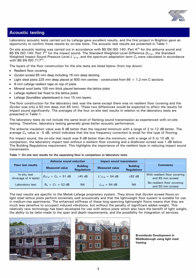
and 50 mm screed The test results are specific to the Metek-Lafarge proprietary system. They show that Gyvlon screed floors on light steel lattice joists perform extremely well acoustically and that the lightweight floor system is suitable for use in medium-rise apartments. The enhanced stiffness of these long spanning lightweight floors means that they are much less sensitive to occupant induced vibrations, but without the penalty of significant added weight. This relatively new technology has been developed for use with lattice joists which also have the benefit of light weight, the ability to be tailor-made to the span and depth requirements, and the possibility for integration of services.
Broomlands Development in Middlesbrough using light steel framing
4
Acoustic Performance: Gyvlon Screed System, used with light steel frames
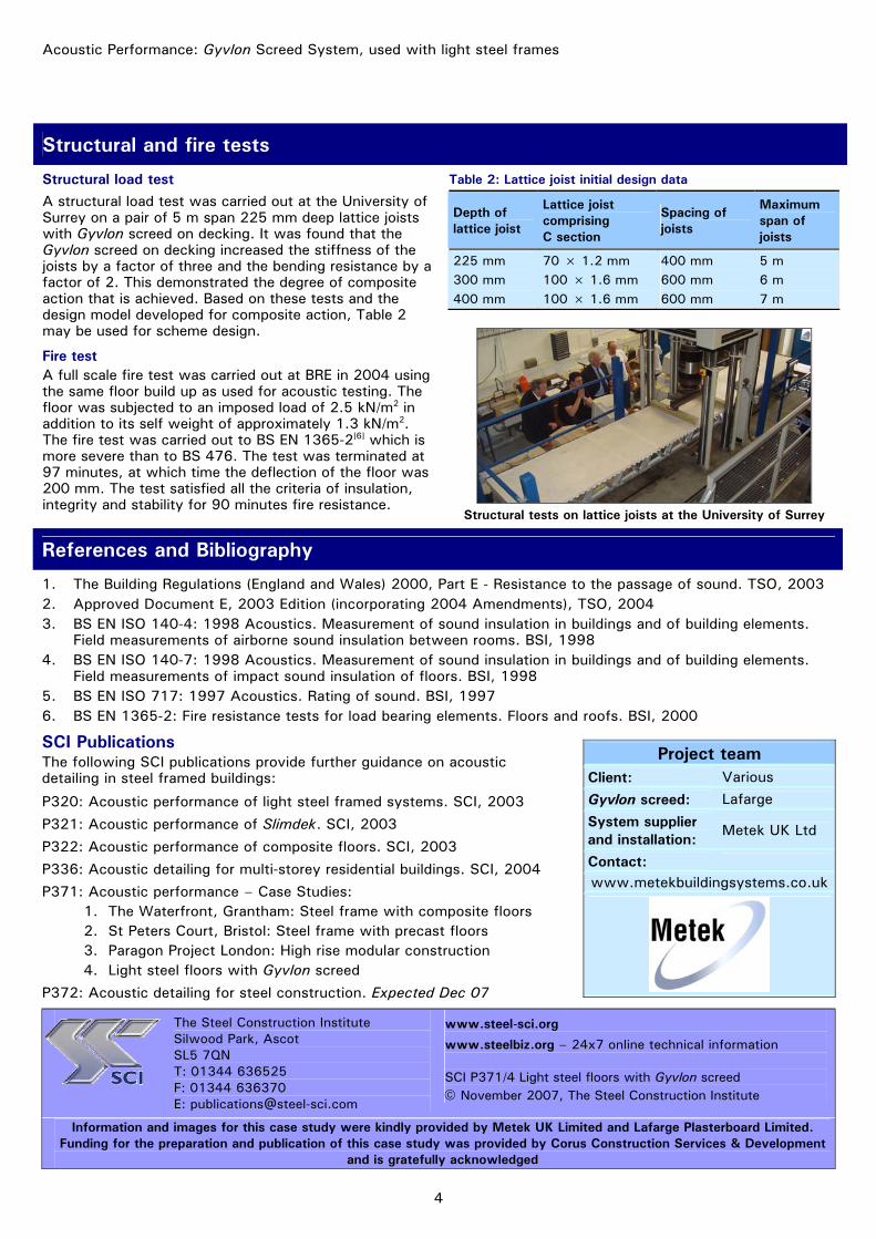
Structural and fire tests
Structural load test A structural load test was carried out at the University of Surrey on a pair of 5 m span 225 mm deep lattice joists with Gyvlon screed on decking. It was found that the Gyvlon screed on decking increased the stiffness of the joists by a factor of three and the bending resistance by a factor of 2. This demonstrated the degree of composite action that is achieved. Based on these tests and the design model developed for composite action, Table 2 may be used for scheme design.
Fire test A full scale fire test was carried out at BRE in 2004 using the same floor build up as used for acoustic testing. The floor was subjected to an imposed load of 2.5 kN/m2 in addition to its self weight of approximately 1.3 kN/m2. The fire test was carried out to BS EN 1365-2[6] which is more severe than to BS 476. The test was terminated at 97 minutes, at which time the deflection of the floor was 200 mm. The test satisfied all the criteria of insulation, integrity and stability for 90 minutes fire resistance.
Table 2: Lattice joist initial design data
Depth of lattice joist
Lattice joist comprising C section
Spacing of joists
Maximum span of joists
225 mm 300 mm 400 mm
70 × 1.2 mm 100 × 1.6 mm 100 × 1.6 mm
400 mm 600 mm 600 mm
5 m 6 m 7 m
Structural tests on lattice joists at the University of Surrey
References and Bibliography
1. The Building Regulations (England and Wales) 2000, Part E - Resistance to the passage of sound. TSO, 2003 2. Approved Document E, 2003 Edition (incorporating 2004 Amendments), TSO, 2004 3. BS EN ISO 140-4: 1998 Acoustics. Measurement of sound insulation in buildings and of building elements.
Field measurements of airborne sound insulation between rooms. BSI, 1998 4. BS EN ISO 140-7: 1998 Acoustics. Measurement of sound insulation in buildings and of building elements.
Field measurements of impact sound insulation of floors. BSI, 1998 5. BS EN ISO 717: 1997 Acoustics. Rating of sound. BSI, 1997 6. BS EN 1365-2: Fire resistance tests for load bearing elements. Floors and roofs. BSI, 2000
SCI Publications The following SCI publications provide further guidance on acoustic detailing in steel framed buildings:
P320: Acoustic performance of light steel framed systems. SCI, 2003
P321: Acoustic performance of Slimdek. SCI, 2003
P322: Acoustic performance of composite floors. SCI, 2003
P336: Acoustic detailing for multi-storey residential buildings. SCI, 2004
P371: Acoustic performance – Case Studies: 1. The Waterfront, Grantham: Steel frame with composite floors 2. St Peters Court, Bristol: Steel frame with precast floors 3. Paragon Project London: High rise modular construction 4. Light steel floors with Gyvlon screed
P372: Acoustic detailing for steel construction. Expected Dec 07
Project team Client: Various
Gyvlon screed: Lafarge
System supplier and installation:
Metek UK Ltd
Contact: www.metekbuildingsystems.co.uk
The Steel Construction Institute Silwood Park, Ascot SL5 7QN T: 01344 636525 F: 01344 636370 E: [email protected]
www.steel-sci.org
www.steelbiz.org – 24x7 online technical information SCI P371/4 Light steel floors with Gyvlon screed © November 2007, The Steel Construction Institute
Information and images for this case study were kindly provided by Metek UK Limited and Lafarge Plasterboard Limited. Funding for the preparation and publication of this case study was provided by Corus Construction Services & Development
and is gratefully acknowledged

1
Building Physics – Acoustic Performance
Acoustic Performance – Case Study 5
Zero4, Plymouth: Hot-rolled steel frame with Slimdek floors
Zero4 is a large residential and commercial development that forms part of the redevelopment of Plymouth city centre. The 10-storey building comprises bars, restaurants and shops on the ground floor, a basement car park, and 120 apartments on the floors above. The apartments range from one bedroom studios to three bedroom luxury duplex apartments.
The structural solution of a hot-rolled steel frame with Slimdek floors was selected because it allows flexibility of layout to accommodate the different size apartments. The Slimdek solution also offered a fast construction programme, which was necessary for the city centre site, and minimum floor-to-floor heights.
The site was previously the home of the Ballard Centre and municipal swimming pool, which were demolished in 2005. The plan form of the new building on the site is rectangular, approximately 58 × 28 m. The structural grid is 7.5 m square and is designed to incorporate 12 flats of various sizes per floor. The building is divided into two parts, one nine and the other 10 storeys high, both with pitched roofs.
The acoustic performance of the floors has substantially exceeded requirements of the Building Regulations, by an average of 10 dB for airborne sound and by an average of 19 dB for impact sound. The walls also easily satisfy the acoustic performance standards required by the Building Regulations[1] and Approved Document E[2].
Acoustic performance summary
Element Sound reduction Measured Required
Floor Airborne 55 dB ≥ 45 dB
Floor Impact 43 dB ≤ 62 dB
Wall Airborne 51 dB ≥ 45 dB
A G J Way
MEng CEng MICE
Curved balcony detail
Project sponsored by:
2
Acoustic Performance: Zero4, Plymouth
Floor and wall details
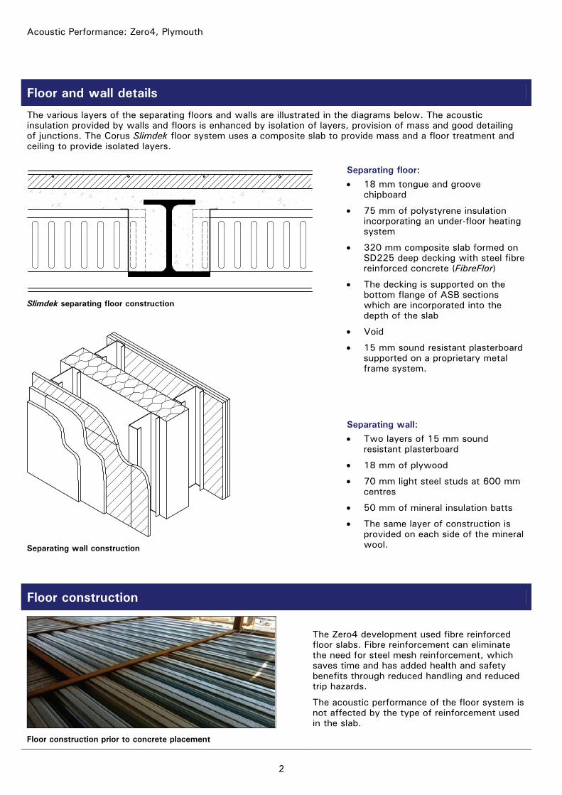
The various layers of the separating floors and walls are illustrated in the diagrams below. The acoustic insulation provided by walls and floors is enhanced by isolation of layers, provision of mass and good detailing of junctions. The Corus Slimdek floor system uses a composite slab to provide mass and a floor treatment and ceiling to provide isolated layers.
Separating floor: • 18 mm tongue and groove
chipboard
• 75 mm of polystyrene insulation incorporating an under-floor heating system
• 320 mm composite slab formed on SD225 deep decking with steel fibre reinforced concrete (FibreFlor)
• The decking is supported on the bottom flange of ASB sections which are incorporated into the depth of the slab
• Void
• 15 mm sound resistant plasterboard supported on a proprietary metal frame system.
Slimdek separating floor construction
Separating wall construction
Separating wall: • Two layers of 15 mm sound
resistant plasterboard
• 18 mm of plywood
• 70 mm light steel studs at 600 mm centres
• 50 mm of mineral insulation batts
• The same layer of construction is provided on each side of the mineral wool.
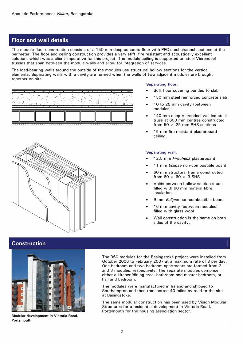
Floor construction
Floor construction prior to concrete placement
The Zero4 development used fibre reinforced floor slabs. Fibre reinforcement can eliminate the need for steel mesh reinforcement, which saves time and has added health and safety benefits through reduced handling and reduced trip hazards.
The acoustic performance of the floor system is not affected by the type of reinforcement used in the slab.

3
Acoustic testing
On-site acoustic testing was carried out in accordance with BS EN ISO 140: Part 4[3] for the airborne sound and BS EN ISO 140: Part 7[4] for the impact sound. The Standard Weighted Level Difference DnT,w, the Standard Weighted Impact Sound Pressure Level L’nT,w and the spectrum adaptation term Ctr were calculated in accordance with BS EN ISO 717[5]. The measured results for the acoustic performance of the separating floors and walls are shown in Tables 1, 2 and 3.
Table 1: On-site acoustic test results for floors
Floor test results Measured Building Regulations
Test 1 56 dB ≥ 45 dB Test 2 64 dB ≥ 45 dB Test 3 62 dB ≥ 45 dB Test 4 61dB ≥ 45 dB Test 5 54 dB ≥ 45 dB Test 6 54 dB ≥ 45 dB Test 7 58 dB ≥ 45 dB Test 8 57 dB ≥ 45 dB Test 9 53 dB ≥ 45 dB
Test 10 54 dB ≥ 45 dB Test 11 56 dB ≥ 45 dB Test 12 56 dB ≥ 45 dB Test 13 48 dB ≥ 45 dB Test 14 50 dB ≥ 45 dB Test 15 48 dB ≥ 45 dB Test 16 47 dB ≥ 45 dB Test 17 59 dB ≥ 45 dB Test 18 55 dB ≥ 45 dB
Airborne (DnT,w + Ctr)
Average 55 dB ≥ 45 dB
Table 2: On-site acoustic test results for walls
Wall test results Measured Building Regulations
Test 1 56 dB ≥ 45 dB Test 2 54 dB ≥ 45 dB Test 3 53 dB ≥ 45 dB Test 4 53 dB ≥ 45 dB Test 5 50 dB ≥ 45 dB Test 6 46 dB ≥ 45 dB Test 7 54 dB ≥ 45 dB Test 8 55 dB ≥ 45 dB Test 9 48 dB ≥ 45 dB
Test 10 48 dB ≥ 45 dB Test 11 48 dB ≥ 45 dB Test 12 52 dB ≥ 45 dB Test 13 54 dB ≥ 45 dB Test 14 49 dB ≥ 45 dB Test 15 53 dB ≥ 45 dB
Airborne (DnT,w + Ctr)
Average 51 dB ≥ 45 dB
Table 3: On-site acoustic test results for floors
Floor test results Measured Building Regulations
Test 1 39 dB ≤ 62 dB Test 2 39 dB ≤ 62 dB Test 3 39 dB ≤ 62 dB Test 4 40 dB ≤ 62 dB Test 5 41 dB ≤ 62 dB Test 6 42 dB ≤ 62 dB Test 7 44 dB ≤ 62 dB Test 8 44 dB ≤ 62 dB Test 9 44 dB ≤ 62 dB
Test 10 44 dB ≤ 62 dB Test 11 49 dB ≤ 62 dB Test 12 42 dB ≤ 62 dB Test 13 43 dB ≤ 62 dB Test 14 44 dB ≤ 62 dB Test 15 46 dB ≤ 62 dB Test 16 44 dB ≤ 62 dB Test 17 47 dB ≤ 62 dB Test 18 45 dB ≤ 62 dB
Impact (L’nT,w)
Average 43 dB ≤ 62 dB
Tests 1 and 2 were conducted by Noise.co.uk in June 2008. The other acoustic tests were performed by SB Consulting Engineering Acoustics Ltd also in June 2008.
The results show that the Building Regulation requirements were exceeded in all cases.
Junction details
The detailing of junctions between separating walls and floors is important to avoid flanking sound paths which reduce the sound insulation provided between adjacent living spaces. Example details are shown on the next page. Joints between wall and ceiling linings are filled with sealant and the wall boards are not in direct contact with the floor treatment. The plasterboard wall linings are not continuous through the wall junction in any direction. The joints between plasterboard layers are staggered and filled with sealant at the corners.

4
Acoustic Performance: Zero4, Plymouth
Sound resilient plasterboard
Plywood
Mineral woolinsulation
Light steelstuds
Cavitybarrier
Junction detail between two separating walls
Junction detail between the floor and external wall
Acousticsealant
Rain screencladdingsystem
Rigidinsulationboard
Insulationbetweenstuds
Acousticsealant
Flankingstrip
Cavitybarrier
References and Bibliography
1. The Building Regulations (England and Wales) 2000, Part E - Resistance to the passage of sound. TSO, 2003 2. Approved Document E, 2003 Edition (incorporating 2004 Amendments), TSO, 2004 3. BS EN ISO 140-4: 1998 Acoustics. Measurement of sound insulation in buildings and of building elements.
Field measurements of airborne sound insulation between rooms. BSI, 1998 4. BS EN ISO 140-7: 1998 Acoustics. Measurement of sound insulation in buildings and of building elements.
Field measurements of impact sound insulation of floors. BSI, 1998 5. BS EN ISO 717: 1997 Acoustics. Rating of sound. BSI, 1997
SCI Publications The following SCI publications provide further guidance on acoustic detailing in steel framed buildings. P320: Acoustic performance of light steel framed systems. SCI, 2003 P321: Acoustic performance of Slimdek. SCI, 2003 P322: Acoustic performance of composite floors. SCI, 2003 P336: Acoustic detailing for multi-storey residential buildings. SCI, 2004 P371: Acoustic performance – Case Studies:
1. The Waterfront, Grantham: A steel frame with composite floors 2. St Peters Court, Bristol: A steel frame with precast floors 3. Paragon Project London: High rise modular construction 4. Light steel floors with Gyvlon screed 5. Zero4, Plymouth: Hot-rolled steel frame with Slimdek floors 6. Vision, Basingstoke: Modular steel frame 7. Riverview, Hereford: Hot-rolled steel frame with composite
fibre-reinforced slab floors 8. Brightwell Court and Minerva Lodge, London: Light steel frame,
walls and floors P372: Acoustic detailing for steel construction. SCI, 2008
Project team Client: Penrose Main contractor and developer:
Prestige Homes
Architect: SMC Architects Structural Engineer:
Airey & Coles
Steelwork contractor:
SIAC Tetbury Steel
Acoustic testing: Noise.co.uk and SB Consulting Engineering Acoustics
The Steel Construction Institute Silwood Park, Ascot SL5 7QN T: 01344 636525 F: 01344 636570 E: [email protected]
www.steel-sci.org
www.steelbiz.org – 24x7 online technical information SCI P371/5 Zero4, Plymouth © January 2009, The Steel Construction Institute
Information for this case study was kindly provided by Prestige Homes. Funding for the preparation and publication of this case study was provided by Corus Construction Services & Development
and is gratefully acknowledged.

1
Building Physics – Acoustic Performance
Acoustic Performance – Case Study 6
Basingstoke: Modular steel frame construction
The Vision modular system from Vision Modular Structures has been used to provide 160 apartments for private and social tenure in the Houndsmill area of Basingstoke. Fully modular construction was used to meet the challenge of fast-build high quality procurement in the residential sector. The building concept was developed by architects PRP acting for Fleming Developments, based on a client’s master plan by HTA Architects.
The development, which consists of 3, 6 and 11 storey buildings, is one of the first major projects in the UK using Vision modules. All the buildings are constructed from load-bearing modules. The system is up to 16 storeys when stabilised by a concrete or braced steel core.
Modular construction was chosen because of speed of construction, minimum disturbance to the nearby hospital, and its ability to achieve the 11 storeys required for this high density project.
The acoustic performance of the floors has substantially exceeded requirements of the Building Regulation, by an average of 8 dB for airborne sound and by an average of 10 dB for impact sound. The walls also easily satisfy the acoustic performance standards required by the Building Regulations[1] and Approved Document E[2].
Acoustic performance summary
Element Sound reduction Measured Required
Floor Airborne 53 dB ≥ 45 dB
Floor Impact 52 dB ≤ 62 dB
Wall Airborne 51 dB ≥ 45 dB
A G J Way
MEng CEng MICE
11 storey modular block
Module during construction
Project sponsored by:
2
Acoustic Performance: Vision, Basingstoke
Floor and wall details
The module floor construction consists of a 150 mm deep concrete floor with PFC steel channel sections at the perimeter. The floor and ceiling construction provides a very stiff, fire resistant and acoustically excellent solution, which was a client imperative for this project. The module ceiling is supported on steel Vierendeel trusses that span between the module walls and allow for integration of services.
The load-bearing walls around the outside of the modules use structural hollow sections for the vertical elements. Separating walls with a cavity are formed when the walls of two adjacent modules are brought together on site.
Separating floor: • Soft floor covering bonded to slab
• 150 mm steel reinforced concrete slab
• 10 to 25 mm cavity (between modules)
• 140 mm deep Vierendeel welded steel truss at 600 mm centres constructed from 50 × 25 mm RHS sections
• 15 mm fire resistant plasterboard ceiling.
Separating wall: • 12.5 mm Firecheck plasterboard
• 11 mm Eclipse non-combustible board
• 60 mm structural frame constructed from 60 × 60 × 3 SHS
• Voids between hollow section studs filled with 60 mm mineral fibre insulation
• 9 mm Eclipse non-combustible board
• 16 mm cavity (between modules) filled with glass wool
• Wall construction is the same on both sides of the cavity.
Construction
Modular development in Victoria Road, Portsmouth
The 360 modules for the Basingstoke project were installed from October 2006 to February 2007 at a maximum rate of 8 per day. One-bedroom and two-bedroom apartments are formed from 2 and 3 modules, respectively. The separate modules comprise either a kitchen/dining area, bathroom and master bedroom, or hall and bedroom.
The modules were manufactured in Ireland and shipped to Southampton and then transported 40 miles by road to the site at Basingstoke.
The same modular construction has been used by Vision Modular Structures for a residential development in Victoria Road, Portsmouth for the housing association sector.
3
Acoustic testing
On-site acoustic testing was carried out in accordance with BS EN ISO 140: Part 4[3] for the airborne sound and BS EN ISO 140: Part 7[4] for the impact sound. The Standard Weighted Level Difference DnT,w, the Standard Weighted Impact Sound Pressure Level L’nT,w and the spectrum adaptation term Ctr were calculated in accordance with BS EN ISO 717[5]. The measured results for the acoustic performance of the separating floors and walls are shown in Table 1 and Table 2, respectively.
Table 1: On-site acoustic test results for floors
Floor test results Measured Building
Regulations
Test 1 52 dB ≥ 45 dB
Test 2 56 dB ≥ 45 dB
Test 3 52 dB ≥ 45 dB
Test 4 50 dB ≥ 45 dB
Airborne (DnT,w + Ctr)
Average 53 dB ≥ 45 dB
Test 1 51 dB ≤ 62 dB
Test 2 51 dB ≤ 62 dB
Test 3 52 dB ≤ 62 dB
Test 4 52 dB ≤ 62 dB
Impact
(L’nT,w)
Average 52 dB ≤ 62 dB
Table 2: On-site acoustic test results for walls
Wall test results Measured Building
Regulations
Test 1 50 dB ≥ 45 dB
Test 2 51 dB ≥ 45 dB
Test 3 51 dB ≥ 45 dB
Test 4 52 dB ≥ 45 dB
Airborne (DnT,w + Ctr)
Average 51 dB ≥ 45 dB
The acoustic tests were conducted by Acoustical Investigation & Research Organisation Ltd (AIRO) in September 2007.
The results show that the Vision modular construction easily satisfies the airborne and impact sound insulation requirements of the Building Regulations.
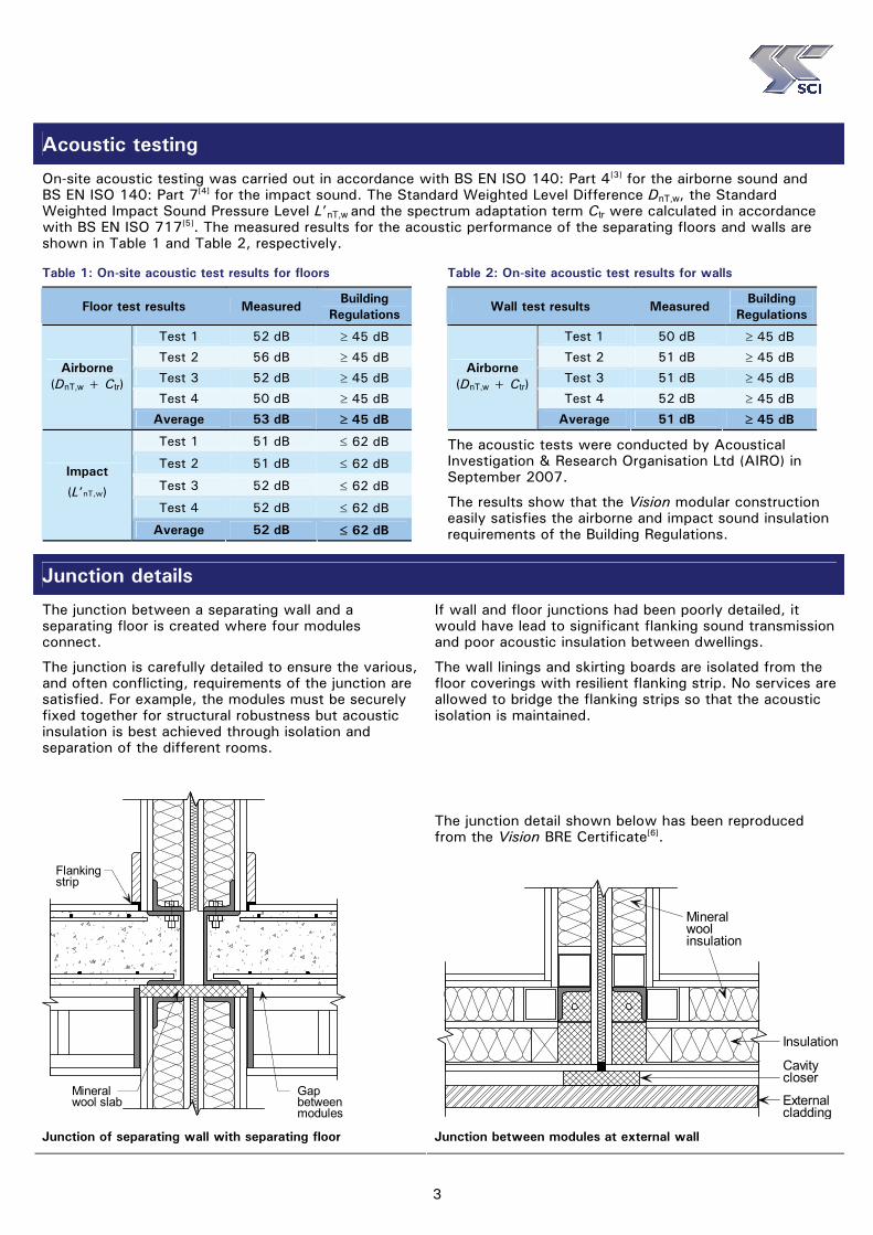
Junction details
The junction between a separating wall and a separating floor is created where four modules connect.
The junction is carefully detailed to ensure the various, and often conflicting, requirements of the junction are satisfied. For example, the modules must be securely fixed together for structural robustness but acoustic insulation is best achieved through isolation and separation of the different rooms.
If wall and floor junctions had been poorly detailed, it would have lead to significant flanking sound transmission and poor acoustic insulation between dwellings.
The wall linings and skirting boards are isolated from the floor coverings with resilient flanking strip. No services are allowed to bridge the flanking strips so that the acoustic isolation is maintained.
The junction detail shown below has been reproduced from the Vision BRE Certificate[6].
Flankingstrip
Mineralwool slab
Gap betweenmodules
Junction of separating wall with separating floor
Externalcladding
Cavitycloser
Insulation
Mineralwoolinsulation
Junction between modules at external wall
4
Acoustic Performance: Vision, Basingstoke
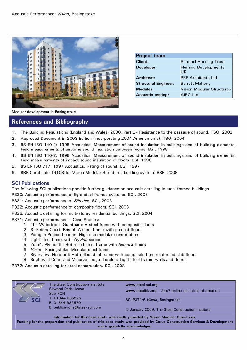
Modular development in Basingstoke
Project team Client: Sentinel Housing Trust Developer: Fleming Developments
UK Architect: PRP Architects Ltd Structural Engineer: Barrett Mahony Modules: Vision Modular Structures Acoustic testing: AIRO Ltd
References and Bibliography
1. The Building Regulations (England and Wales) 2000, Part E - Resistance to the passage of sound. TSO, 2003 2. Approved Document E, 2003 Edition (incorporating 2004 Amendments), TSO, 2004 3. BS EN ISO 140-4: 1998 Acoustics. Measurement of sound insulation in buildings and of building elements.
Field measurements of airborne sound insulation between rooms. BSI, 1998 4. BS EN ISO 140-7: 1998 Acoustics. Measurement of sound insulation in buildings and of building elements.
Field measurements of impact sound insulation of floors. BSI, 1998 5. BS EN ISO 717: 1997 Acoustics. Rating of sound. BSI, 1997 6. BRE Certificate 14108 for Vision Modular Structures building system. BRE, 2008
SCI Publications The following SCI publications provide further guidance on acoustic detailing in steel framed buildings. P320: Acoustic performance of light steel framed systems. SCI, 2003 P321: Acoustic performance of Slimdek. SCI, 2003 P322: Acoustic performance of composite floors. SCI, 2003 P336: Acoustic detailing for multi-storey residential buildings. SCI, 2004 P371: Acoustic performance – Case Studies:
1. The Waterfront, Grantham: A steel frame with composite floors 2. St Peters Court, Bristol: A steel frame with precast floors 3. Paragon Project London: High rise modular construction 4. Light steel floors with Gyvlon screed 5. Zero4, Plymouth: Hot-rolled steel frame with Slimdek floors 6. Vision, Basingstoke: Modular steel frame 7. Riverview, Hereford: Hot-rolled steel frame with composite fibre-reinforced slab floors 8. Brightwell Court and Minerva Lodge, London: Light steel frame, walls and floors
P372: Acoustic detailing for steel construction. SCI, 2008
The Steel Construction Institute Silwood Park, Ascot SL5 7QN T: 01344 636525 F: 01344 636570 E: [email protected]
www.steel-sci.org
www.steelbiz.org – 24x7 online technical information SCI P371/6 Vision, Basingstoke © January 2009, The Steel Construction Institute
Information for this case study was kindly provided by Vision Modular Structures. Funding for the preparation and publication of this case study was provided by Corus Construction Services & Development
and is gratefully acknowledged.

1
Building Physics – Acoustic Performance
Acoustic Performance – Case Study 7
Riverview, Hereford: Hot-rolled steel frame with composite fibre-reinforced slab floors
Riverview is a Perfection Homes development of 23 luxury apartments in the heart of the city of Hereford with accommodation provided over five storeys. Many of the apartments offer views over the River Wye. The project includes new-build, renovation and conversion.
There are three main parts to the Riverview development. The largest part is a new-build five-storey steel frame structure with composite beams and slabs. The slabs are reinforced with the Corus FibreFlor system rather than traditional mesh reinforcement. The west side of the development consists of an existing steel frame that has been renovated and supplemented with new steel sections. A local landmark Art Deco façade has also been retained and restored. The third part of the development is the conversion of a Wesleyan Chapel that dates back to 1829. The chapel has been converted into four apartments and includes the addition of a contemporary architectural rear extension.
The steel framed parts of this development use the Robust Detail E-FS-1 for the acoustic separating floors. Therefore, because a Robust Detail floor has been used, the floors were not required to be tested for acoustic performance. However, the separating walls did need to be tested. Testing has shown that the walls satisfied the acoustic performance standards required by the Building Regulations[1] and Approved Document E[2].
Acoustic performance summary
Element Sound reduction Measured1 Required2
Floor Airborne (56 dB) ≥ 45 dB
Floor Impact (38 dB) ≤ 62 dB
Wall Airborne 53 dB ≥ 45 dB
1 Values for the floors are the average performance for Robust Detail E-FS-1[5]. 2 These are the values required by Building Regulations. Robust Details are
required to provide an improved level of acoustic performance.
A G J Way
MEng CEng MICE
View from across the river
Structural steel frame
Project sponsored by:

2
Acoustic Performance: Riverview, Hereford
Floor and wall details
The detailed constructions of the separating walls and floors are illustrated and summarised below. The floor construction is the ever-popular composite floor slab with a floor treatment above and a suspended plasterboard ceiling below.
By satisfying certain detailing requirements, the floor becomes a Robust Detail separating floor (E-FS-1). The concrete density must be at least 2200 kg/m3 (i.e. normal weight concrete), the slab must be at least 130 mm thick at the deepest point and at least 80 mm thick at the shallowest point, and the distance from the top of the slab to the underside of the ceiling must be at least 300 mm.
Separating floor: • 18 mm tongue and groove
chipboard walking surface
• 60 mm deep timber battens with 10 mm pre-bonded resilient layer
• Under-floor heating system installed between battens incorporating thermal quilt (Not shown in diagram)
• 150 mm deep FibreFlor composite slab on trapezoidal decking ComFlor 70, supported on rolled steel beam
• Plasterboard ceiling supported on proprietary metal frame system.
Walls The Riverview development uses several different types of wall construction. Separating walls (between dwellings) are blockwork lined with plasterboard on dabs and plaster skimmed. Internal walls (within dwellings) are generally either light steel stud walls or timber stud walls. Both types of stud wall are lined with plasterboard.
Acoustic testing
On-site acoustic testing was not required for the separating floors because they were registered with Robust Details Limited and complied with the detailing requirements of Robust Detail E-FS-1. The acoustic performance values for the separating floor E-FS-1 are shown in Table 1. The separating walls did require on-site testing. The tests were carried out in accordance with BS EN ISO 140: Part 4[3] for the airborne sound. The Standard Weighted Level Difference DnT,w and the spectrum adaptation term Ctr were calculated in accordance with BS EN ISO 717[4]. The measured results for the acoustic performance of the separating walls are shown in Table 2.
The acoustic testing was carried out by JSD Air and Acoustic Testing (Buildings) Ltd. The results show that the performance required by the Building Regulations for separating walls has been achieved.
Table 1: Acoustic test results for floor (E-FS-1)
Floor test results Measured Building
Regulations
Minimum 50 dB ≥ 45 dB
Maximum 64 dB ≥ 45 dB Airborne
(DnT,w + Ctr) Average 56 dB ≥ 45 dB
Minimum 24 dB ≤ 62 dB
Maximum 46 dB ≤ 62 dB Impact
(L’nT,w) Average 38 dB ≤ 62 dB
Source: Robust Details Handbook – Third Edition[5]
Table 2: On-site acoustic test results for walls
Wall test results Measured Building
Regulations
Test 1 50 dB ≥ 45 dB
Test 2 52 dB ≥ 45 dB
Test 3 55 dB ≥ 45 dB
Test 4 56 dB ≥ 45 dB
Airborne (DnT,w + Ctr)
Average 53 dB ≥ 45 dB
3
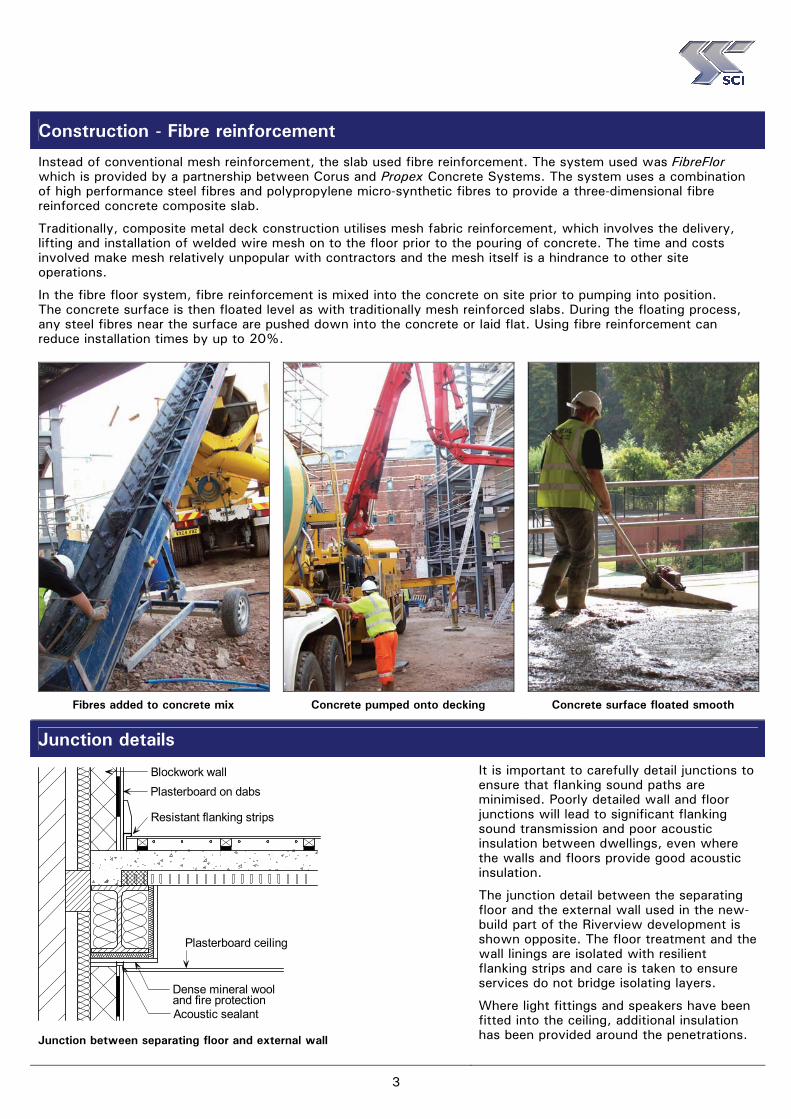
Construction - Fibre reinforcement
Instead of conventional mesh reinforcement, the slab used fibre reinforcement. The system used was FibreFlor which is provided by a partnership between Corus and Propex Concrete Systems. The system uses a combination of high performance steel fibres and polypropylene micro-synthetic fibres to provide a three-dimensional fibre reinforced concrete composite slab.
Traditionally, composite metal deck construction utilises mesh fabric reinforcement, which involves the delivery, lifting and installation of welded wire mesh on to the floor prior to the pouring of concrete. The time and costs involved make mesh relatively unpopular with contractors and the mesh itself is a hindrance to other site operations.
In the fibre floor system, fibre reinforcement is mixed into the concrete on site prior to pumping into position. The concrete surface is then floated level as with traditionally mesh reinforced slabs. During the floating process, any steel fibres near the surface are pushed down into the concrete or laid flat. Using fibre reinforcement can reduce installation times by up to 20%.
Fibres added to concrete mix
Concrete pumped onto decking
Concrete surface floated smooth
Junction details
Dense mineral wooland fire protection
Blockwork wallPlasterboard on dabs
Resistant flanking strips
Acoustic sealant
Plasterboard ceiling
Junction between separating floor and external wall
It is important to carefully detail junctions to ensure that flanking sound paths are minimised. Poorly detailed wall and floor junctions will lead to significant flanking sound transmission and poor acoustic insulation between dwellings, even where the walls and floors provide good acoustic insulation.
The junction detail between the separating floor and the external wall used in the new-build part of the Riverview development is shown opposite. The floor treatment and the wall linings are isolated with resilient flanking strips and care is taken to ensure services do not bridge isolating layers.
Where light fittings and speakers have been fitted into the ceiling, additional insulation has been provided around the penetrations.

4
Acoustic Performance: Riverview, Hereford
Buildings around Riverview courtyard
Project team Client and Developer:
Perfection Homes Limited
Architect: Hook Mason Associates
Structural Engineer:
Neil Foster
Steelwork contractor:
Pinnacle Structures Limited
Agent: Arkwright Owens Chartered Surveyors
Acoustic testing:
JSD Air and Acoustic Testing (Buildings) Ltd
References and Bibliography
1. The Building Regulations (England and Wales) 2000, Part E - Resistance to the passage of sound. TSO, 2003 2. Approved Document E, 2003 Edition (incorporating 2004 Amendments), TSO, 2004 3. BS EN ISO 140-4: 1998 Acoustics. Measurement of sound insulation in buildings and of building elements.
Field measurements of airborne sound insulation between rooms. BSI, 1998 4. BS EN ISO 717: 1997 Acoustics. Rating of sound. BSI, 1997 5. Robust Details Handbook, Third Edition. Resistance to the passage of sound. Robust Details Limited, 2007
SCI Publications The following SCI publications provide further guidance on acoustic detailing in steel framed buildings. P320: Acoustic performance of light steel framed systems. SCI, 2003 P321: Acoustic performance of Slimdek. SCI, 2003 P322: Acoustic performance of composite floors. SCI, 2003 P336: Acoustic detailing for multi-storey residential buildings. SCI, 2004 P371: Acoustic performance – Case Studies:
1. The Waterfront, Grantham: A steel frame with composite floors 2. St Peters Court, Bristol: A steel frame with precast floors 3. Paragon Project London: High rise modular construction 4. Light steel floors with Gyvlon screed 5. Zero4, Plymouth: Hot-rolled steel frame with Slimdek floors 6. Vision, Basingstoke: Modular steel frame 7. Riverview, Hereford: Hot-rolled steel frame with composite fibre-reinforced slab floors 8. Brightwell Court and Minerva Lodge, London: Light steel frame, walls and floors
P372: Acoustic detailing for steel construction. SCI, 2008
The Steel Construction Institute Silwood Park, Ascot SL5 7QN T: 01344 636525 F: 01344 636570 E: [email protected]
www.steel-sci.org
www.steelbiz.org – 24x7 online technical information SCI P371/7 Riverview, Hereford © January 2009, The Steel Construction Institute
Information for this case study was kindly provided by Perfection Homes Limited. Funding for the preparation and publication of this case study was provided by Corus Construction Services & Development
and is gratefully acknowledged.

1
Building Physics – Acoustic Performance
Acoustic Performance – Case Study 8
Brightwell Court and Minerva Lodge, London: Fusion light steel structural framing
Brightwell Court (shown above) and Minerva Lodge are both 4-storey, light steel framed care homes constructed in London by Fusion Building Systems. Brightwell court contains 35 apartments and Minerva Lodge contains 54.
These properties have replaced out-dated buildings and now provide quality homes to meet the needs of older people. The residents have the opportunity to continue living independent lives in homes that are built and designed to Lifetime Homes Standards (www.lifetimehomes.org.uk).
The walls and floors, which form the structural frame, are constructed from light steel framing. Large open space was achieved on the ground floor of Brightwell Court by incorporating hot-rolled steel transfer structures above the ground floor. The bathrooms at Minerva Lodge were fully integrated prefabricated pods.
The acoustic performance of the floors has substantially exceeded requirements of the Building Regulations, by an average of 7 dB for airborne sound and by an average of 10 dB for impact sound. The walls also easily satisfy the acoustic performance standards required by the Building Regulations[1] and Approved Document E[2]
, exceeding the requirements, by an average of 9 dB.
Acoustic performance summary
Element Sound reduction Measured Required
Floor Airborne 52 dB ≥ 45 dB
Floor Impact 52 dB ≤ 62 dB
Wall Airborne 54 dB ≥ 45 dB
A G J Way
MEng CEng MICE
Light steel joist
Light steel framing
Project sponsored by:
2
Acoustic Performance: Brightwell Court and Minerva Lodge, London
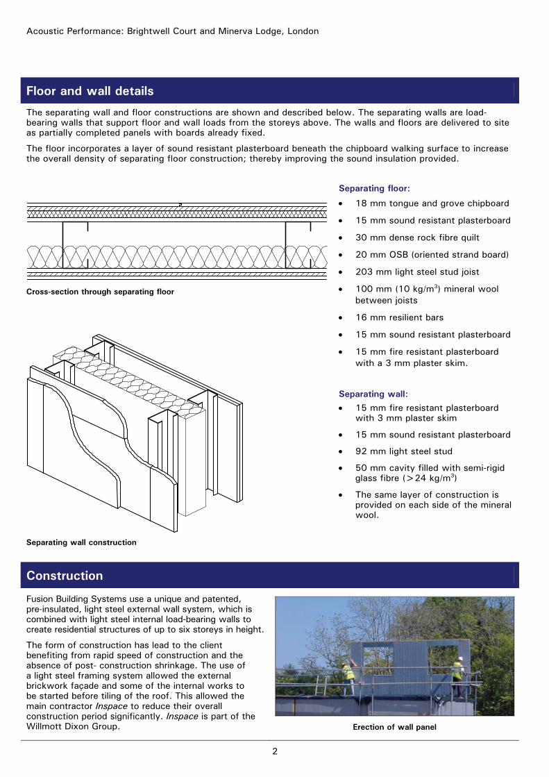
Floor and wall details
The separating wall and floor constructions are shown and described below. The separating walls are load-bearing walls that support floor and wall loads from the storeys above. The walls and floors are delivered to site as partially completed panels with boards already fixed.
The floor incorporates a layer of sound resistant plasterboard beneath the chipboard walking surface to increase the overall density of separating floor construction; thereby improving the sound insulation provided.
Separating floor:
• 18 mm tongue and grove chipboard
• 15 mm sound resistant plasterboard
• 30 mm dense rock fibre quilt
• 20 mm OSB (oriented strand board)
• 203 mm light steel stud joist
• 100 mm (10 kg/m3) mineral wool between joists
• 16 mm resilient bars
• 15 mm sound resistant plasterboard
• 15 mm fire resistant plasterboard with a 3 mm plaster skim.
Cross-section through separating floor
Separating wall construction
Separating wall: • 15 mm fire resistant plasterboard
with 3 mm plaster skim
• 15 mm sound resistant plasterboard
• 92 mm light steel stud
• 50 mm cavity filled with semi-rigid glass fibre (>24 kg/m3)
• The same layer of construction is provided on each side of the mineral wool.
Construction
Fusion Building Systems use a unique and patented, pre-insulated, light steel external wall system, which is combined with light steel internal load-bearing walls to create residential structures of up to six storeys in height.
The form of construction has lead to the client benefiting from rapid speed of construction and the absence of post- construction shrinkage. The use of a light steel framing system allowed the external brickwork façade and some of the internal works to be started before tiling of the roof. This allowed the main contractor Inspace to reduce their overall construction period significantly. Inspace is part of the Willmott Dixon Group.
Erection of wall panel

3
Acoustic testing
On-site acoustic testing was carried out in accordance with BS EN ISO 140: Part 4[3] for the airborne sound and BS EN ISO 140: Part 7[4] for the impact sound. The Standard Weighted Level Difference DnT,w, the Standard Weighted Impact Sound Pressure Level L’nT,w and the spectrum adaptation term Ctr were calculated in accordance with BS EN ISO 717[5]. The measured results for the acoustic performance of the separating floors and walls are shown in Table 1 and Table 2, respectively.
Table 2: On-site acoustic test results for walls
Wall test results Measured Building Regulations
Test 1 51 dB ≥ 45 dB Test 2 55 dB ≥ 45 dB Test 3 54 dB ≥ 45 dB Test 4 52 dB ≥ 45 dB Test 5 54 dB ≥ 45 dB Test 6 45 dB ≥ 45 dB Test 7 52 dB ≥ 45 dB Test 8 49 dB ≥ 45 dB Test 9 60 dB ≥ 45 dB
Test 10 58 dB ≥ 45 dB Test 11 53 dB ≥ 45 dB Test 12 52 dB ≥ 45 dB Test 13 58 dB ≥ 45 dB Test 14 58 dB ≥ 45 dB Test 15 54 dB ≥ 45 dB Test 16 54 dB ≥ 45 dB
Airborne (DnT,w + Ctr)
Average 54 dB ≥ 45 dB
Note: Tests 1 to 4 in Tables 1 and 2 are from Brightwell Court, Tests 5 to 16 are from Minerva Lodge. All the acoustic tests were conducted by Sound Research Laboratories Limited (SRL). It can be seen from the tests that the system gives consistent acoustic performance for walls and floors. The consistency is, at least in part, due to the factory controlled conditions in which the system is produced. The test results show that the Building Regulation requirements for separating walls and floors were easily satisfied.
Table 1: On-site acoustic test results for floors
Floor test results Measured Building Regulations
Test 1 52 dB ≥ 45 dB Test 2 55 dB ≥ 45 dB Test 3 47 dB ≥ 45 dB Test 4 50 dB ≥ 45 dB Test 5 53 dB ≥ 45 dB Test 6 52 dB ≥ 45 dB Test 7 52 dB ≥ 45 dB Test 8 51 dB ≥ 45 dB Test 9 53 dB ≥ 45 dB
Test 10 52 dB ≥ 45 dB Test 11 50 dB ≥ 45 dB Test 12 51 dB ≥ 45 dB Test 13 51 dB ≥ 45 dB Test 14 51 dB ≥ 45 dB Test 15 52 dB ≥ 45 dB Test 16 52 dB ≥ 45 dB
Airborne (DnT,w + Ctr)
Average 52 dB ≥ 45 dB Test 1 54 dB ≤ 62 dB Test 2 53 dB ≤ 62 dB Test 3 54 dB ≤ 62 dB Test 4 52 dB ≤ 62 dB Test 5 51 dB ≤ 62 dB Test 6 52 dB ≤ 62 dB Test 7 52 dB ≤ 62 dB Test 8 52 dB ≤ 62 dB Test 9 50 dB ≤ 62 dB
Test 10 51 dB ≤ 62 dB Test 11 52 dB ≤ 62 dB Test 12 50 dB ≤ 62 dB Test 13 52 dB ≤ 62 dB Test 14 50 dB ≤ 62 dB Test 15 52 dB ≤ 62 dB Test 16 52 dB ≤ 62 dB
Impact (L’nT,w)
Average 52 dB ≤ 62 dB
Reverberation of sound Requirement E3 of The Building Regulations[1] is that the common internal areas (i.e. corridors and hallways) of buildings containing flats or rooms for residential purposes should be designed and constructed so that reverberation of sound within the common area is within reasonable limits. Approved Document E[2] states that Requirement E3 can be satisfied by providing sufficient surface area of sound absorbent material.
In Brightwell Court and Minerva Lodge Requirement E3 was satisfied by providing a layer of Class C absorber ceiling in all corridors and common areas. The additional ceiling is demountable and is suspended below the plasterboard ceiling described on page 2.
The requirement to control reverberation must be considered during the structural design stage as it may affect storey heights and ceiling dead load.

4
Acoustic Performance: Brightwell Court and Minerva Lodge, London
Resilientbars
Resilientflankingstrip
Floor to wall junction detail
The same project team was used for both the Brightwell Court and Minerva Lodge projects.
Project team: Client: Circle Anglia Architect: PRP Architects Developer: Inspace Light steel framing:
Fusion Building Systems
Contractor: Inspace Acoustic testing:
Sound Research Laboratories Limited
References and Bibliography
1. The Building Regulations (England and Wales) 2000, Part E - Resistance to the passage of sound. TSO, 2003 2. Approved Document E, 2003 Edition (incorporating 2004 Amendments), TSO, 2004 3. BS EN ISO 140-4: 1998 Acoustics. Measurement of sound insulation in buildings and of building elements.
Field measurements of airborne sound insulation between rooms. BSI, 1998 4. BS EN ISO 140-7: 1998 Acoustics. Measurement of sound insulation in buildings and of building elements.
Field measurements of impact sound insulation of floors. BSI, 1998 5. BS EN ISO 717: 1997 Acoustics. Rating of sound. BSI, 1997
SCI Publications The following SCI publications provide further guidance on acoustic detailing in steel framed buildings. P320: Acoustic performance of light steel framed systems. SCI, 2003
P321: Acoustic performance of Slimdek. SCI, 2003
P322: Acoustic performance of composite floors. SCI, 2003
P336: Acoustic detailing for multi-storey residential buildings. SCI, 2004
P371: Acoustic performance – Case Studies: 1. The Waterfront, Grantham: A steel frame with composite floors 2. St Peters Court, Bristol: A steel frame with precast floors 3. Paragon Project London: High rise modular construction 4. Light steel floors with Gyvlon screed 5. Zero4, Plymouth: Hot-rolled steel frame with Slimdek floors 6. Vision, Basingstoke: Modular steel frame 7. Riverview, Hereford: Hot-rolled steel frame with composite fibre-reinforced slab floors 8. Brightwell Court and Minerva Lodge, London: Light steel frame, walls and floors
P372: Acoustic detailing for steel construction. SCI, 2008
The Steel Construction Institute Silwood Park, Ascot SL5 7QN T: 01344 636525 F: 01344 636570 E: [email protected]
www.steel-sci.org
www.steelbiz.org – 24x7 online technical information SCI P371/8 Brightwell Court and Minerva Lodge, London © January 2009, The Steel Construction Institute
Information for this case study was kindly provided by Fusion Building Systems. Funding for the preparation and publication of this case study was provided by Corus Construction Services & Development
and is gratefully acknowledged.