acoustic performance of hybrid renewable polyurethane...
TRANSCRIPT

ACOUSTIC PERFORMANCE OF HYBRID RENEWABLE POLYURETHANE
BLENDED WITH SYNTHETIC EPOXY FOAM WITH AND WITHOUT
TITANIUM DIOXIDE FILLER UPON IRRADIATED EXPOSURE
NOOR QURATUL AINE BINTI ADNAN
Universiti Tun Hussein Onn Malaysia
ACOUSTIC PERFORMANCE OF HYBRID RENEWABLE POLYURETHANE
BLENDED WITH SYNTHETIC EPOXY FOAM WITH AND WITHOUT
TITANIUM DIOXIDE FILLER UPON IRRADIATED EXPOSURE
NOOR QURATUL AINE BINTI ADNAN
A thesis submitted in fulfilment of the requirement for the award of the
Degree of Master of Mechanical Engineering
Faculty of Mechanical and Manufacturing Engineering
Universiti Tun Hussein Onn Malaysia
JANUARI 2016

iii
DEDICATION
“Special dedicated to my beloved family, my lecturers and my friends who always
gave me support and encouragement”
iv
ACKNOWLEDGEMENT
First and foremost, I would like to express grateful thanks to my respectful
supervisor, PM Dr Anika Zafiah Mohd Rus whose encouragement, guidance, and
support from the initial till final level which enabled me to develop an understanding
of the subject. Her willingness to motivate me contributed tremendously to the
project.
Thank you to Mr. Fazlannuddin Hanur bin Harith who help me during
specimen fabrication stage and also during the mechanical testing. Thank to Mr. Md
Zainorin bin Kasron who helps me to set up the sound absorption test.
I would not forget to thank to my beloved family, my lecturers and my fellow
friends for their concern and support and helps when I faced difficulty in the
research.
Finally, I wish to extend my gratitude to University Tun Hussein Onn
Malaysia (UTHM) for supporting and providing students with the training and
education for a brighter future. Last but not least, thank you God for making the
project successful.

v
ABSTRACT
Waste cooking oils are problematic disposal especially in the developed countries.
Options for disposing of waste cooking oil are limited. Therefore, in this research,
vegetable waste cooking oil is used as raw material to produce renewable polymer
foam as an alternative product. This is started with the crosslinking of renewable
monomer with isocyanate to generated renewable polymer foam. Further process is
comprised with the addition of synthetic epoxy or titanium dioxide (TiO2) by
different ratio (wt/wt) of renewable monomer. Fabricated samples was divided into
three types of foam namely as epoxy foam (EF), renewable polymer foam (RF)
loaded with different percentage loading of titanium dioxide (TiO2) as filler namely
as EF1-3 and RF1-3 and epoxy/renewable polymer foam (ERF). At prolonged UV
irradiation exposure, the density of all specimens was increase but the pore sizes
were decreased as the percentages of TiO2 were increased. For EF, RF and EFR
samples shows highest at frequency absorption level (Hz) of α at each individual
category with 0.965 at 2943 Hz, 0.995 at 3106 Hz, 0.945 at 3684 Hz. The lowest α at
frequency absorption level (Hz) of EF, RF and ERF is 0.878 at 3181 Hz, 0.823 at
3184 Hz, 0.876 at 3526 Hz respectively. Meanwhile for composite samples EF1-3 and
RF1-3 shows higher α at absorption frequency level (Hz) of each individual category
with 0.968 at 3928 Hz, 0.998 at 3728 Hz and lowest α at frequency absorption level
(Hz) of 0.836 at 3512 Hz, 0.878 at 3915 Hz respectively. As a general remark, the
highest loading of TiO2 show RF3 resulted in reduced of cell sizes after UV
irradiation exposure and contributed the higher α. Thus, the morphological study of
SEM was revealed that RF3 have smallest cell sizes after UV irradiation exposure
with 681 μm diameter. In other words, the decrement in cell sizes of higher TiO2
loading was improved the sound absorption property at prolonged UV irradiation
hours 1000 hours.

vi
ABSTRAK
Sisa minyak masak adalah bahan buangan yang menyumbang kepada masalah
pelupusan bagi di negara-negara membangun. Pilihan untuk melupuskan sisa minyak
masak adalah terhad. Dalam kajian ini, sisa minyak masak sayuran digunakan
sebagai bahan mentah untuk menghasilkan span polimer yang boleh diperbaharui.
Ianya bermula dengan silangan monomer dan isosianat untuk menghasilkan span
polimer yang diperbaharui. Proses selanjutnya terdiri dengan penambahan sintetik
epoxy atau titanium dioksida (TiO2) dengan nisbah yang berbeza (berat/berat) untuk
monomer yang diperbaharui. Penghasilan samples dibahagikan kepada tiga jenis
iaitu span epoksi (EF), span polimer yang diperbaharui yang dicampurkan dengan
perbezaaan peratusan titanium dioksida (TiO2) yang dinamakan EF1-3 dan RF1-3 dan
epoksi/span polimer yang diperbaharui (ERF). Pada pendedahan sinaran ultra (UV),
ketumpatan semua sample telah meningkat tetapi saiz liang telah berkurang
mengikut peningkatan peratusan TiO2. Untuk EF, RF dan ERF sample menunjukkan
tahap tertinggi penyerapan frekuensi (Hz) bagi α pada setiap kategori adalah
sebanyak 0.965 pada 2943 Hz, 0.995 pada 3106 Hz, 0.945 pada 3684 Hz.
Penyerapan frekuensi (Hz) terendah bagi α untuk EF, RF, ERF masing-masing
adalah 0.878 pada 3181 Hz, 0.823 pada 3184 Hz, 0.876 pada 3526 Hz. Manakala,
bagi sample komposit EF1-3 dan RF1-3 tahap tertinggi penyerapan frekuensi (Hz) bagi
α pada setiap kategori adalah 0.968 pada 3928 Hz, 0.998 pada 3728 Hz dan
penyerapan frekuensi (Hz) terendah bagi α masing-masing adalah 0.836 pada 3512
Hz, 0.878 pada 3915 Hz. Umumnya, peningkatan TiO2 menunjukkan penurunan
bilangan saiz liang selepas pendedahan sinaran ultra (UV) dan menyumbang kepada
kenaikkan α. Kemudian, kajian morfologi SEM menunjukkan span RF3
menghasilkan saiz sel diameter terkecil selepas pendedahan sinaran UV iaitu 681
µm. Kesimpulan, penurunan sel saiz pada peratusan tertinggi TiO2 dapat membantu
penyerapan bunyi dan pada kenaikkan penyinaran UV pada 1000 jam.

vii
TABLE OF CONTENTS
CONTENTS PAGE
TITLE i
DECLARATION ii
DEDICATION iii
ACKNOWLEDGEMENT iv
ABSTRACT v
ABSTRAK vi
TABLE OF CONTENTS vii
LIST OF TABLES x
LIST OF FIGURES xii
LIST OF SYMBOLS xv
LIST OF ABBREVIATIONS xvi
LIST OF APPENDIXES xviii
CHAPTER 1 INTRODUCTION 1
1.1 Background of study 1
1.2 Problem Statement 3
1.3 Hypothesis of research 4
1.4 Objective of research 4
1.5 Scope of research 5
1.6 Signification of research 5
1.7 Thesis organization 6
viii
CHAPTER 2 LITERATURE REVIEW 7
2.1 Introduction 7
2.2 Renewable polymer 7
2.2.1 Renewable polymer from renewable
resources
9
2.2.2 Composite and important of vegetable oils in
polymer production
13
2.3 Formation of polymer foam 17
2.3.1 Foam Formula and Generation 20
2.4 Polyurethane foam 26
2.5 Raw materials of Polyurethane Foam (PU) foam 29
2.5.1 Polyol 29
2.5.2 Flexible isocyanate 31
2.5.3 Covalent crosslink 32
2.6 Properties of polyurethane (PU) foam and it’s
composite
33
2.7 Composite of Polymer foam 40
2.7.1 Titanium dioxide (TiO2) in polymer 41
2.7.2 Titanium dioxide (TiO2) as photocatalyst 43
2.8 Sound absorption properties of polymer (PU) and its
composite foam
45
2.9 The effect of UV irradiation on acoustic behaviour
of polymer (PU) and its composite foam
51
CHAPTER 3 RESEARCH METHODOLOGY 56
3.1 Introduction 56
3.2 Methodology chart 48
3.3 Fabrication of Epoxy foam (EF), renewable polymer
foam (RF) and it’s composite (EF1-3 and RF1-3) and
epoxy/renewable polymer foam (ERF) composition
ratio foam production process
58
3.4 Physical characterization tests of EF, RF and it’s
composite (EF1-3 and RF1-3) and ERF
63
ix
3.4.1 Density and porosity measurements 64
3.4.2 Scanning Electron Microscope (SEM) 65
3.5 Mechanical characterization of EF, RF and it’s
composite (EF1-3 and RF1-3) and ERF on sound
acoustic test
66
3.5.1 Sound absorption test of EF, RF and it’s
composite (EF1-3 and RF1-3) and ERF
67
3.6 UV irradiation Test of EF, RF and it’s composite
(EF1-3 and RF1-3) and ERF samples
69
3.7 Noise reduction coefficient of of EF, RF and it’s
composite (EF1-3 and RF1-3) and ERF samples
72
CHAPTER 4 RESULTS AND DISCUSSION 73
4.1 Introduction 73
4.2 Density 73
4.3 Porosity analysis 75
4.4 EF, RF and it’s composite (EF1-3 and RF1-3) and ERF
foam morphology structure by Scanning Electron
Microscope (SEM)
79
4.5 Acoustic behaviour of EF, RF and it’s composite
(EF1-3 and RF1-3) and ERF
83
4.6 Noise reduction coefficient of of EF, RF and it’s
composite (EF1-3 and RF1-3) and ERF
88
CHAPTER 5 CONCLUSION AND RECOMMENDATION 90
5.1 Introduction 90
5.2 Future recommendation 92
REFERENCES 93
APPENDICES 90
VITA 133
LIST OF PUBLICATION 134
x
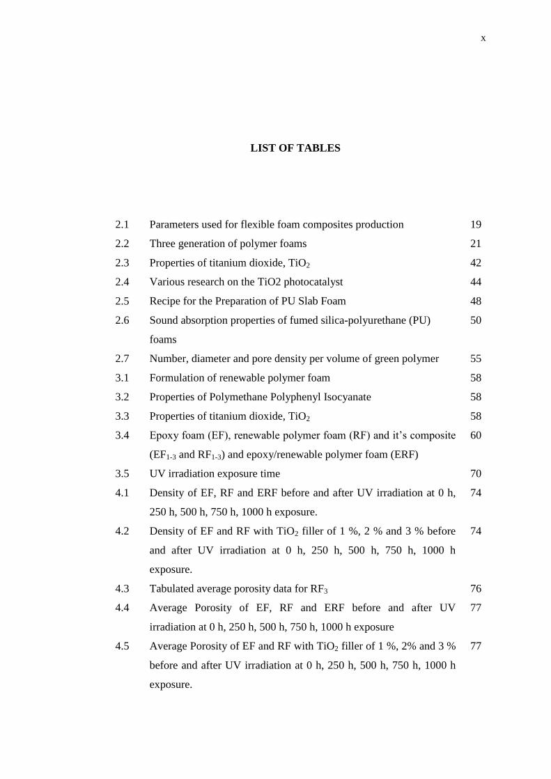
LIST OF TABLES
2.1 Parameters used for flexible foam composites production 19
2.2 Three generation of polymer foams 21
2.3 Properties of titanium dioxide, TiO2 42
2.4 Various research on the TiO2 photocatalyst 44
2.5 Recipe for the Preparation of PU Slab Foam 48
2.6 Sound absorption properties of fumed silica-polyurethane (PU)
foams
50
2.7 Number, diameter and pore density per volume of green polymer 55
3.1 Formulation of renewable polymer foam 58
3.2 Properties of Polymethane Polyphenyl Isocyanate 58
3.3 Properties of titanium dioxide, TiO2 58
3.4 Epoxy foam (EF), renewable polymer foam (RF) and it’s composite
(EF1-3 and RF1-3) and epoxy/renewable polymer foam (ERF)
60
3.5 UV irradiation exposure time 70
4.1 Density of EF, RF and ERF before and after UV irradiation at 0 h,
250 h, 500 h, 750 h, 1000 h exposure.
74
4.2 Density of EF and RF with TiO2 filler of 1 %, 2 % and 3 % before
and after UV irradiation at 0 h, 250 h, 500 h, 750 h, 1000 h
exposure.
74
4.3 Tabulated average porosity data for RF3 76
4.4 Average Porosity of EF, RF and ERF before and after UV
irradiation at 0 h, 250 h, 500 h, 750 h, 1000 h exposure
77
4.5 Average Porosity of EF and RF with TiO2 filler of 1 %, 2% and 3 %
before and after UV irradiation at 0 h, 250 h, 500 h, 750 h, 1000 h
exposure.
77

xi
4.6 The higher average sound absorption coefficient [α] EF, RF and
ERF of UV irradiation exposure hours
85
4.7 The average sound absorption coefficient [α] of EF1, EF2 and EF3 of
UV exposure hours
86
4.8 The average sound absorption coefficient [α] of RF1, RF2 and RF3 of
UV exposure time
87

xii
LIST OF FIGURES
1.1 Major application of PU foam 1
2.1 The cyclic process of biodegradable polymer yielded through
fermentation by agricultural processes, back into useful natural polymers
8
2.2 Mechanism of photodegradation 12
2.3 Chemical structure of fats and oils 14
2.4 Hydrolysis reaction produces glycerol and fatty acids 14
2.5 The structure of triglycerides and the five most common fatty acid
substituents for vegetable oils
15
2.6 Gelation reaction or PU cross-linkage reaction 21
2.7 Blow reaction between isocyanate and water 22
2.8 Development of polyurethane (PU) foam 23
2.9 Morphology of polyurethane (PU) foam 24
2.10 Sample sputter-coater with gold 26
2.11 Polyurethane Pre-polymers 27
2.12 Applications of polyurethane (PU) foams 28
2.13 Polyether polyols made from ethylene oxide (top) and propylene oxide
(bottom). The initiator used, for illustration purposes, is glycerol and R
and R* represent the same structures as shown
29
2.14 Reaction of triolein with ozone and ethylene glycol 30
2.15 Diisocyanates commonly used in foaming: a) 2,4-toluene diisocyanate,
b) 2,6-toluene diisocyanate, c) 4,4-methylene diphenyl diisocyanate, d)
2,4-methylene diphenyl diisocyanate, e) 2,2-methylene diphenyl
diisocyanate, and f) polymeric MDI Common used diisocyanate.
31
2.16 The secondary reactions of isocyanate 32
xiii
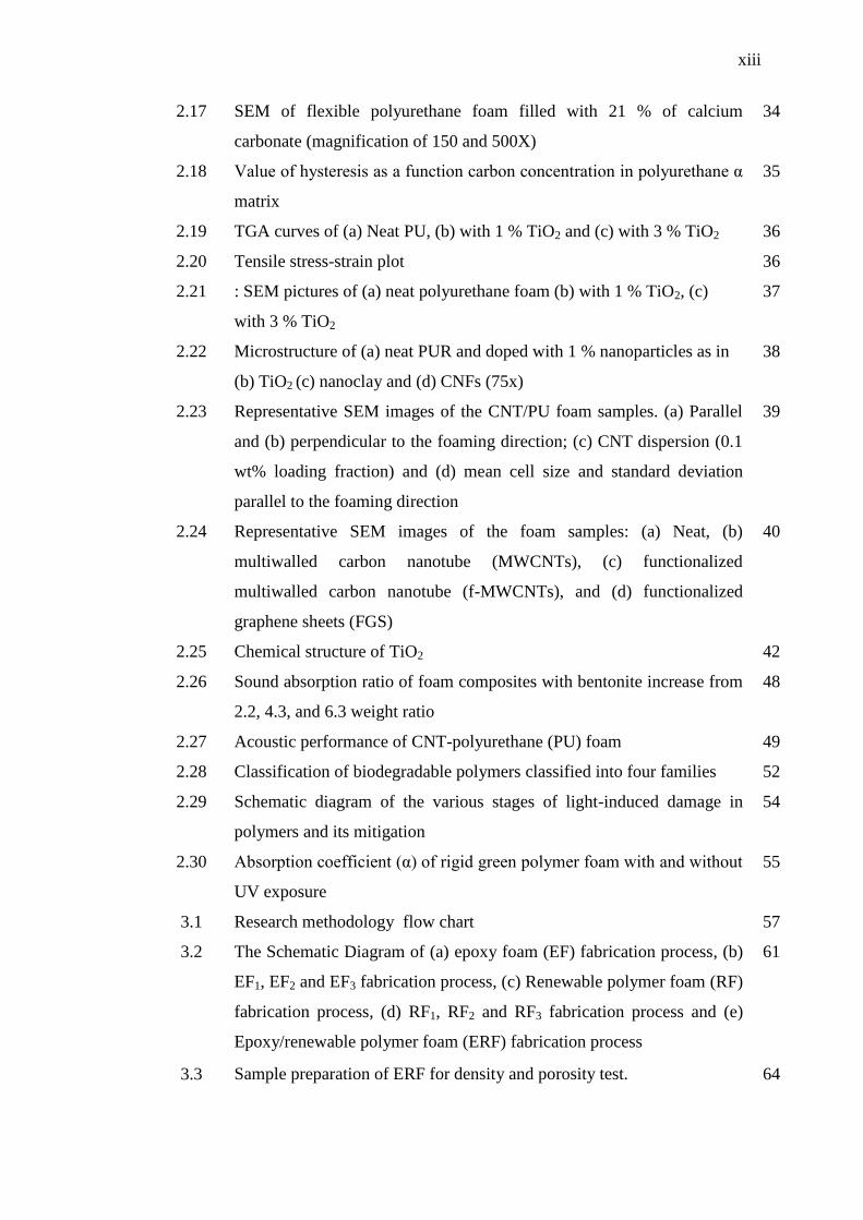
2.17 SEM of flexible polyurethane foam filled with 21 % of calcium
carbonate (magnification of 150 and 500X)
34
2.18 Value of hysteresis as a function carbon concentration in polyurethane α
matrix
35
2.19 TGA curves of (a) Neat PU, (b) with 1 % TiO2 and (c) with 3 % TiO2 36
2.20 Tensile stress-strain plot 36
2.21 : SEM pictures of (a) neat polyurethane foam (b) with 1 % TiO2, (c)
with 3 % TiO2
37
2.22 Microstructure of (a) neat PUR and doped with 1 % nanoparticles as in
(b) TiO2 (c) nanoclay and (d) CNFs (75x)
38
2.23 Representative SEM images of the CNT/PU foam samples. (a) Parallel
and (b) perpendicular to the foaming direction; (c) CNT dispersion (0.1
wt% loading fraction) and (d) mean cell size and standard deviation
parallel to the foaming direction
39
2.24 Representative SEM images of the foam samples: (a) Neat, (b)
multiwalled carbon nanotube (MWCNTs), (c) functionalized
multiwalled carbon nanotube (f-MWCNTs), and (d) functionalized
graphene sheets (FGS)
40
2.25 Chemical structure of TiO2 42
2.26 Sound absorption ratio of foam composites with bentonite increase from
2.2, 4.3, and 6.3 weight ratio
48
2.27 Acoustic performance of CNT-polyurethane (PU) foam 49
2.28 Classification of biodegradable polymers classified into four families 52
2.29 Schematic diagram of the various stages of light-induced damage in
polymers and its mitigation
54
2.30 Absorption coefficient (α) of rigid green polymer foam with and without
UV exposure
55
3.1 Research methodology flow chart 57
3.2 The Schematic Diagram of (a) epoxy foam (EF) fabrication process, (b)
EF1, EF2 and EF3 fabrication process, (c) Renewable polymer foam (RF)
fabrication process, (d) RF1, RF2 and RF3 fabrication process and (e)
Epoxy/renewable polymer foam (ERF) fabrication process
61
3.3 Sample preparation of ERF for density and porosity test. 64

xiv
3.4 Mettler Toledo Weighing for density test of polymer foam, EF, RF and
it’s composite (EF1-3 and RF1-3) and ERF
65
3.5 The (a) SEM machine and (b) Auto Fined Coater 66
3.6 T-Jaw 3600 Vertical Band Saw machine 66
3.7 Image of ERF foam used in sound absorption test with 100 mm and 28
mm diameter
68
3.8 Set-up of sound absorption for ERF samples 68
3.9 The diagram of impedence tube kit 69
3.10 QUV Accelerated Weathering Tester HD-703 70
3.11 ERF samples holder mounted on the chamber 71
3.12 Yellowing of ERF polymer foam: (a) before UV irradiation exposure
and (b) after UV irradiation exposure of acoustic sound absorption
sample.
71
4.1 Schematic drawing of surfaces in core of foam composite 79
4.2 The SEM micrographs of EF, RF and ERF of UV irradiations exposure
hours
80
4.3 The SEM micrographs of EF1, EF2 and EF3 of UV irradiation exposure
hours
81
4.4 The SEM micrographs of RF1, RF2 and RF3 of UV irradiation exposure
hours
82
4.5 Mean cell size of EF, RF and it’s composite (EF1-3 and RF1-3) and ERF
from SEM microscope graph
83
4.6 The higher average sound absorption coefficient [α] EF, RF and ERF of
UV irradiation exposure hours
85
4.7 The average sound absorption coefficient [α] of EF1, EF2 and EF3 of UV
exposure hours
86
4.8 The average sound absorption coefficient [α] of RF1, RF2 and RF3 of UV
exposure time
87
4.9 NRC of EF, RF and ERF with UV irradiation exposure hours 88
4.10 NRC of EF1-3 and RF1-3 with UV irradiation exposure hours 89

xv
LIST OF SYMBOLS
α - Sound absorption coefficient or viscoelastic parameter
ρ - Density
W, M, m - Total mass or total riding mass
EF - 100 % Epoxy with 0 % Renewable monomer
RF - 0 % Epoxy with 100 % Renewable monomer
ERF80/20 - 80 % Epoxy with 20 % Renewable monomer
ERR60/40 - 60 % Epoxy with 40 % Renewable monomer
ERF40/60 - 40 % Epoxy with 60 % Renewable monomer
ERF20/80 - 20 % Epoxy with 80 % Renewable monomer
EF1 - 1 % of TiO2 for Epoxy
EF2 - 2 % of TiO2 for Epoxy
EF3 - 3 % of TiO2 for Epoxy
RF1 - 1 % of TiO2 for Renewable monomer
RF2 - 2 % of TiO2 for Renewable monomer
RF3 - 3 % of TiO2 for Renewable monomer
WW - Mass of an immersed and suspended specimen in air.
WD - Mass of air dried specimen
WS - Mass of immerse and suspend specimen in liquid
xvi
LIST OF ABBREVIATIONS
UV - Ultraviolet
TiO2 - Titanium dioxide
PU - Polyurethane
PET - Polyethylene Terephthalate
wt. - weight
UTHM - Universiti Tun Hussein Onn Malaysia
SEM - Scanning Electron Microscopy
ASTM - American Society for Testing and Materials
MDI - Methylene Diphenyl Diisocyanate
NRC - Noise Reduction Coefficient
PLA - Polylactic asid
CaCO3 - Calcium Carbonate or Calcite
BP - Biodegradable polymer
CO2 - Carbon Dioxide
TAG - Triacylglycerol
CNFS - Carbon nanofibres
CNTS - Carbon nanotube
OH - Hydroxide
O - Oxygen
CFD - Compression force deflection
MWCNTs - Multiwalled carbon nanotube
f-MWCNTs - Functionalized multiwalled carbon nanotube
FGS - Functionalized graphene sheets
NA-MMT - Sodium montmorillonite

xvii
EF - 100 % Epoxy 0 % Renewable monomer, 0.5 % of
isocyanate
RF - 80 % Epoxy 20 % Renewable monomer, 0.5 % of
isocyanate
ERF80/20 - 60 % Epoxy 40 % Renewable monomer, 0.5 % of
isocyanate
ERF60/40 - 40 % Epoxy 60 % Renewable monomer, 0.5 % of
isocyanate
ERF40/60 - 20 % Epoxy 80 % Renewable monomer, 0.5 % of
isocyanate
ERF20/80 - 0 % Epoxy 100 % Renewable monomer, 0.5 % of
isocyanate
EF1 - 100 % of Epoxy, 0.5 % of isocyanate, 1.0 % of TiO2
EF2 - 100 % of Epoxy, 0.5 % of isocyanate, 2.0 % of TiO2
EF3 - 100 % of Epoxy, 0.5 % of isocyanate, 3.0 % of TiO2
RF1 - 100 % of Renewable monomer, 0.5 % of isocyanate,
1.0 % of TiO2
RF2 - 100 % of Renewable monomer, 0.5 % of isocyanate,
2.0 % of TiO2
RF3 - 100 % of Renewable monomer, 0.5 % of isocyanate,
3.0 % of TiO2

xviii
LIST OF APPENDICES
A Porosity determination of EF, RF and it’s composite (EF1-3
and RF1-3) and ERF
91
Example calculation for porosity of renewable polymer
foam (RF)
93
B Mean cell size of EF, RF and it’s composite (EF1-3 and
RF1-3) and ERF
94
C Sound absorption coefficient (α) of EF, RF and it’s
composite (EF1-3 and RF1-3) and ERF
97
D Specification of titanium dioxide (TiO2) 131

CHAPTER 1
INTRODUCTION
1.1 Background of study
Polymeric foams are important and versatile material due to their outstanding
strength-to-weight ratio, resilience, electrical, thermal and acoustic insulating
properties, among other characteristics. Polyurethane is one of the largest and most
versatile families of polymer (Verdego et al., 2009). Some notable applications of
this foam material include mattresses, upholstery, furniture, footwear and textiles in
our homes and office, and as packing, appliances, electronics, machinery and
foundry, and as cushioning material in automobiles as well as in the industries as
shown in Figure 1.1.
Figure 1.1: Major application of flexible PU foam (Polyurethane Foam Association
1992, 1996 and 1997)

2
Furthermore, as refer to Klempner and Sendijarevic (2004), polymeric foams
shows excellence in being lightweight, strength to weight ratio performance, and
most importantly, if offers a degree of comfort, protection, and utility not matched by
other single material. By proper choice of raw materials, additive and manufacturing
technology, the properties of flexible PU foam can be changed to satisfy desired
application. Generally, the characteristic of flexible PU foam can be soft or rigid
chemical composition of raw material, in particular polyol and isocyanate.
During the formation of flexible PU foam, polyol and isocyanate are mixed to
form polyurethane linkage. However, due to the fluctuation of oil prices, these petro-
chemical feed stocks would rise in price and this in fact could influence the
production cost of automotive seats (Latinwo et al., 2010a).
Various experiment aimed in improving both the mechanical properties and
cost effectiveness of renewable polymer foam has been conducted. One attempt of
achieving this involved the chemical modification of its structure. Another
modification involved the use of fillers to achieve flexible polyurethane / filler
composite formation. Inorganic filler materials are available as nano-, micro-, and
macro-scale crystals (Latinwo et al., 2010b). According Sant’anna et al.,(2008),
among the inorganic material utilized as filler, notable ones include: calcium
carbonate, aluminium hydroxide, silica, titanium dioxide and talc. Some of the
organic materials more commonly used are carbon black and natural fibers. Their
effects on plastic foam material have been known to strongly depend on their sizes,
aspect ratio, hybrid morphology, and dispersion quality. It is also well known that
fillers increase cell density and decrease cell size. By affecting the macroscopic cell
geometry, it can act as reinforcement material in polyurethane foam composites
(Latinwo et al., 2010b).
Therefore in this research, waste cooking oil has been utilized and is
converted into monomer to produce renewable polymer foam. Renewable polymer
foam with and without filler has been prepared to measure the mechanical and
physical properties as well as it’s resistance to ultraviolet (UV) irradiation exposure
on the polymer foam. The properties of polymer were examined by using density
test, Scanning Electron Microscope (SEM), UV test, and sound absorption test
according to ASTM standard.

3
1.2 Problem Statement
In polymer industry, vegetable oil which represents a major potential source of
chemicals has been utilized as an alternative feedstock for monomers. PU foam made
from castor oil has existed for many years. Other oil such as soybean oil and
rapeseed oil-based polyol has been used to make PU foams as well (Narine et al.,
2007).
In recent year, waste cooking oil has proven to be problematic material.
Many people cannot solve the problem and did not know how to manage the problem
instead of poured the oil into the drain or toilet. By recycling, the waste oils to
substitute the petroleum based product as well as by improving the physical and
mechanical properties and to reduce the environment pollution.
Furthermore, the use of renewable sources in the preparation of various
industrial materials has been revitalized because of the environment concerns. Thus,
the problem is to generate new idea and formulae either in automotive, packaging or
building structure application by improving the performance of the foam. In specific,
the problem of noise absorbing material in an automotive field or packaging needed
alternative new material that can be used to replace substitute the existing products
(Hulme and Goodhead, 2003).
Moreover, industries that produce flexible polyurethane foams use fillers to
modify the material’s properties as well as to reduce manufacturing cost. This is also
to achieve dimensional stability, ease of retraction from the mold and service density
(Usman et al., 2012). A variety of particulate or fibrous fillers is used for cost
reduction or mechanical properties improvement. The fillers are mainly include:
silica, glass fibers, aluminium hydroxide or starch, CaCO3, Ca3(PO4)2, CaSO4 and
talc and even nanostructured fillers, such as carbon nanotube and nanoclays (Mello et
al.,2009).
According to Usman et al., (2012), when adding a filler to a polymer, it is to
form a conjugated biphasic material. The tension applied to the polymeric matrix will
be transferred to the disperse filler phase in which it’s provide superior properties
than the pure polymer. Thus, in this research, waste cooking oil monomer is used
mixed with cross-linker to form renewable polymer foam. The selected filler such as
titanium dioxide (TiO2) is used to retard the degradation of polymeric materials as
well as renewable polymer foam. The degradation of polymer could be occurs in a

4
wide variety of environment and service conditions, and very often limits the service
lifetime.
In addition, polymer properties can be slightly affected during their
processing, storage, and transportation, the most significant degradation occurs
during expose to the environment. The aging is severe for polymeric materials
because it combines the photo-physical and photo-chemical effect. The combine
effects are due to ultraviolet (UV) irradiation with oxidative and hydrolytic effect of
the outdoor environment (Xu et al., 2011).
1.3 Hypothesis of research
i. To prove that a proper weight percentage (wt %) of epoxy foam and
treated renewable polymer foam may offer good acoustic
characteristic material.
ii. The epoxy foam and renewable polymer foam with and without TiO2
have the potential to increase the dissipation of energy through
absorption and sound.
1.4 Objective of research
i. To fabricated foam types samples namely as epoxy foam (EF),
renewable polymer foam (RF) loaded with different percentage
loading of titanium dioxide (TiO2) as filler namely as EF1-3 and RF1-3
and epoxy/renewable polymer foam (ERF).
ii. To determine EF, RF and it’s composite (EF1-3 and RF1-3) and ERF
for density and porosity before and after UV irradiation exposure up
to 1000 hours.
iii. To UV irradiate EF, RF and it’s composite (EF1-3 and RF1-3) and ERF
for sound and noise absorption.

5
1.5 Scope of research
i. Literature review on the fundamental of polymer foam fabrication
process with different percentage ratio of renewable monomer
blended with synthetic epoxy and titanium dioxide (TiO2).
ii. The fabrication process is to prepare the epoxy foam (EF), renewable
polymer foam (RF) loaded with different percentage loading of
titanium dioxide (TiO2) as filler namely as EF1-3 and RF1-3 and
epoxy/renewable polymer foam (ERF).
iii. The physical and mechanical properties is determine on EF, RF and
it’s composite (EF1-3 and RF1-3) and ERF such as density, porosity and
morphology characteristic by Scanning Electron Microscope (SEM).
iv. The acoustic sound and noise of UV irradiation exposure
characteristic of EF, RF and it’s composite (EF1-3 and RF1-3) and ERF
by using sound absorption test according to ASTM standard is
conducted.
1.6 Signification of research
i. This research intended to improve the sound absorbing properties of
EF, RF and it’s composite (EF1-3 and RF1-3) and ERF to be used in
motor vehicle and packaging industry as well as any suitable
application.
ii. To determine whether this research is able to increase the value of
sound absorption coefficient (α) of EF, RF and it’s composite (EF1-3
and RF1-3) and ERF
iii. The EF, RF and it’s composite (EF1-3 and RF1-3) and ERF had been
developed especially for automotive application, particularly in the
focus on improving the comfort and tranquillity for a variety of uses.
iv. The EF, RF and it’s composite (EF1-3 and RF1-3) and ERF can be
replace as the component in application which offer a great
production cost reduction due to the used of waste cooking oil.

6
1.7 Thesis organization
CHAPTER 1 has highlighted the general introduction on this research, background
of study, problem statement, hypothesis, objective, scope and its significance of
research. It discussed the reason of research aimed in developing of FC using wood
filler which can provide better sound absorption.
In CHAPTER 2, reviews of literature were focusing on epoxy, renewable
polymer, foam production and its parameter and sound absorption coefficient.
CHAPTER 3 shows the methodology that used to conduct the whole study.
The technique density and porosity preparation, the physical and morphology
characteristic test is described in details.
CHAPTER 4 and CHAPTER 5 cover the results and discussion of the
experimental carried out from this research. The particles of foam are discussed in
CHAPTER 4. It also shows the physical properties of the foam characterized using
SEM and density measurement. In CHAPTER 5, the results of sound absorption
before and after UV irradiation exposure were discussed in details.
CHAPTER 2
LITERATURE REVIEW
2.1 Introduction
This chapter is discussed and reviewed previous studies from other researchers on
development and characteristics of renewable polymer foam or blended with epoxy
and titanium dioxide (TiO2) as sound and noise absorption application. The testing
methods used for evaluating the foam composite. It is to provide more information
on in renewable polymer foam blended with synthetic epoxy foam and TiO2 filler on
its mechanical and physical properties for any new application.
2.2 Renewable polymer
Renewable polymer is polymers produced by living organisms. Since they are
polymers, it is monomeric units are covalently bonded to form larger structure. There
are three main classes of renewable polymer based on the differing monomeric units
used and the structure of the renewable polymer formed. The resulting properties of
these materials, from light weight with enhanced mechanical properties to greater
sustainability, has meant a growing number of application in such areas as building,
construction, automotive engineering and etc.
Renewable polymer can be sustainable, carbon neutral and are always
renewable, because they are made from plant materials which can be grown year on
year indefinitely. These plant materials come from agricultural non-food crops.
Therefore, the use of renewable polymers would create a sustainable industry. In

8
contrast, the feed stock for polymers derived from petrochemicals will eventually run
out (Mohanty et al.,1999). In addition, renewable polymer has the potential to cut
carbon emission and reduce carbon dioxide (CO2) quantities in the atmosphere. This
is because CO2 released as they degrade and can be reabsorbed by crops grown to
replace them. Thus, this makes them close to carbon neutral.
Renewable polymers are biodegradable, and some are also compostable.
Some renewable polymer is biodegradable: they are broken down into CO2 and water
by microorganisms. Some of these biodegradable renewable polymers are
compostable: they can be put into an industrial composting process and will break
down by 90 % within six months. Renewable polymer that does this can be marked
with a „compostable‟ symbol (Mohanty et al., 1999). Packing marked with this
symbol can be put into industrial composting processes and will break down within
six months or less.
Figure 2.1: The Cyclic process of renewable polymer yielded through fermentation
by agricultural processes, back into useful natural polymers (Mohanty et al., 1999)

9
2.2.1 Renewable polymer from Renewable Resources
Large amount of plastic waste generated by industries poses serious environmental
problem which may require for total degradation (Mantia et al., 2008). An approach
to decrease the solid waste is to substitute conventional material with biodegradable
raw materials to reduce costs and to enhance the degradation of the final product. By
renewable resources is meant agricultural product mainly from five principal crops:
soybean, oil palm, rapseed, sunflower and coconut where the materials are
synthesized by sunlight (Suresh et al., 2007). Many researches have provided
overviews of various partially and completely biodegradable resins and composites.
Among these are various cellulose, protein and starch based materials, soy protein
with low cost, easy availability and biodegradability.
The respect of the environment is a capital point in a sustainable development
context. We should act in this way to preserve fossil resources and reduce the
pollution of the Earth. The fabrication of industrial product must consume less
energy and the raw materials must be in priority renewable resources, in particular
from agriculture origin. Currently, two approaches are explored to minimize the
impact of polymers on the environment:
i. The design of polymeric materials for long duration (e.g. aeronautic devices,
construction materials, coating and containers), these materials must combine
unalterability and be fashioned preferentially from renewable resources (e.g
plant oil in thermoset, wood fiber in composites materials).
ii. Technological innovation designed for the production of polymer for short
duration (e.g. disposable package, agricultural mulches, horticultural post,
etc) must have the intention of fast biodegradability. Most biodegradability
polymers belong to thermoplastics (e.g. poly (lactic acid),
poly(hydoroxyalkanoate), poly(vinyl alchohol)) or plant polymers (e.g.
cellulose and starch). Thermoplastics from polyolefin are not biodegradable,
even if some of them have pro-oxidant additives making them photo and or
thermo degradable (Lucas et al.,2008)
10
As an effort to develop polymers with high modulus and strength, more
polymerizable functional groups are introduced onto the triglyceride molecules,
resulting in high cross-linked network. The high cross-link density leads to polymers
with high glass transition temperature, high modulus and high strength. However,
with increasing cross-link density, the flexible character of the fatty acid chains
changes as the mobility decreases, making them very brittle with poor resistance to
crack initiation and propagation (Lu et al., 2008).
The most well-know and widely used renewable biodegradable polymer is
those from polysaccharides. The principal polysaccharide of interest to polymer
chemists is starches, which is polymer of glucose. In addition to these, fibers,
polylactic asid (PLA) and traicylglycerols of oils are of particular interst for the
development of biodegradable industrial polymers.
Narine and Kong (2005) presented the starch is the most common polymer in
plants. Large amounts of starch can be obtained from tubers such as potatoes, from
cereals such as rice and from seeds such as corn. The starch molecule is heavily
hydrated as it contains many exposed hydroxyl group, which form hydrogen bond on
coming into contact with water. The starch –filled polyethylene films become porous
after extraction of starch. This porous film can then be readily invaded by micro-
organisms and rapidly saturated with oxygen, thereby increasing polymer
degradation by biological and oxidative methods.
Alternatively waste cooking oil is used because of their potential to substitute
petrochemical derivatives. Waste cooking oil usually has large amount of fatty acids,
triglycerides, polymers and decomposition product (Guner et al., 2006). This residue
poured down the drain, resulting in problem for waste water treatment or plant and
energy loss, or it‟s integrated into the food chain through animal feeds, thus
becoming a potential cause of health problem.
The term "waste cooking oil" includes any vegetable oil (e.g., soybean oil,
peanut oil, sunflower oil, linseed oil, coconut oil, cottonseed oil, canola oil, corn oil,
safflower oil, walnut oil, castor oil, tung oil, etc.), animal fat (e.g., lard, fish oil,
poultry fat, tallow, etc.), or by product or combination that has been heated to a high
temperature or used in the preparation of food or other products.
Traditionally, these waste oils were used as an additive to animal feed.
However, many harmful compounds are produced during the frying of vegetable oils.
The European Union (EU), aware of this problem, banned the use of waste cooking

11
oils in the composition of animal feed in 2002. Most of the toxic compounds in the
waste cooking oil are oxidation products from fatty acids, especially from
polyunsaturated fatty acids (Bautista. L. F., Vicente, G., 2009).
Waste cooking oil can pose a pollution hazard if not handled properly. To
prevent pollution of waterways and clogging of private and municipal drain systems,
restaurants and other food preparation facilities typically storage of used cooking oil
and employ sewage traps to filter grease out of waste water streams. Yellow and
brown grease (also commonly referred to as trap grease, sewage grease, or black
grease) are two forms of waste cooking oil that are readily available in bulk
quantities. Yellow grease is of a slightly higher quality than brown grease and
typically has a free fatty acid (FFA) content of between about 4 and 15 weight
percent, while brown grease typically has a FFA content of up to about 60 weight
percent. The current supply of yellow and brown grease exceeds the demand for
these feedstocks.
Wang, Y., (2007) studied that waste cooking oils (WCO), which contain large
amounts of free fatty acids produced in restaurants, are collected by the
environmental protection agency in the main cities of China and should be disposed
in a suitable way. Most restaurants, especially fast food restaurants, use commercial
deep frying units to cook food items such as, for example, french fries, chicken, or
fish by submersing the food items in hot cooking oil. The cooking oil (typically
vegetable oil) has a limited shelf life, as it degrades and becomes contaminated by
pieces of food as well as water and fats released from food during the cooking
process. As a result, the cooking oil is changed on a regular basis.
Photodegradation changes the physical and optical properties of the plastic.
The most damaging effects are the visual effect (yellowing), the loss of mechanical
properties of the polymers, the changes in molecular weight and the molecular
weight distribution for the same (Martin et al., 2003; Hamid et al., 1995; Andrady et
al., 1993). PE and PP films when exposed to solar UV radiation readily lose their
extensibility, mechanical integrity and strength along with decrease in their average
molecular weight (Abadal et al., 2006).

12
In photo-oxidative degradation, mechanism involves auto-oxidation cycle
comprising various steps shown in Figure 2.2
Figure 2.2: Mechanism of photodegradation (Hanaor and Sorrell, 2011).
The mechanism of photodegradation involves: (a) initiation, (b) propagation
reaction, and (c) termination reactions.
Initiation is where the absorption of UV light that has sufficient energy to
break the chemical bonds in the main polymer chain leads to the initiation of
mechanism responsible for polymer degradation. It involves a radical chain
mechanism for the formation of initial radical. Different initiation steps under varied
conditions have been undertaken in different polymers.
The propagating reactions of auto-oxidation cycle are common to all carbon
backbone polymers. These reactions lead to generation of hydroperoxide species and
are not directly led to backbone cleavage but are the key intermediates to further
reactions as shown in Figure 2.2. Hydroperoxide species generated in propagating
step lead to backbone degradation through cleavage of hydroperoxide O-O bond
followed by b-scission.
The termination of photodegradation is achieved by „mopping up‟ the free
radicals to create inert products. This occurs naturally by combining free radicals or
assisted by using stabilizers in the plastic. Macroalkyl radicals may combine to give
a crosslinked, branched or disproportionated product. Peroxyl radicals eventually
Initiation
Initiator
Propagation
Termination

13
terminate by reaction with other radicals to give dialkyl peroxides, carbonyl species
or alcohols.
Oxidation usually leads to increase brittleness and deterioration in strength.
Generally, the mechanism of oxidative degradation is free radical formation and is
initiated by the thermal or photolytic cleavage of bonds. The free radicals then react
with oxygen to yield peroxides and hydroperoxides.
It should be indicated that irradiated polymeric materials undergo a series of
oxidative reactions that lead to photochemical degradation (Zhang et al., 1999) and
with consequences like brittleness, loss of brightness, and color changes. Besides the
cross-linking of the polymeric processes, a number of other changes may take place
in polymeric chains during photodegradation (Rabek, 1995; Fechine, 2002).
2.2.2 Composition and important of vegetable oils in polymer production
Vegetable oils are one of the cheapest and most abundant, annually renewable
natural resources available in large quantities from various oilseeds, and are now
being used in an increasing number of industrial applications. Vegetable oils, such as
soybean oil, palm oil and rapeseed oil are extracted primarily from the seeds of
oilseed plants and have a wide variety of application: as food, fuels (biofuels),
lubricants, paints, cosmetics, pharmaceuticals, plasticizers, and construction material.
They are also attractive monomers for polymer chemistry due to their natural
abundance and reactive functionality.
In recent years, there has been a growing trend in using vegetable oil as raw
material in resin production. Among the advantages are:
i. The vegetable oils are renewable in perpetuity,
ii. Products derived from natural oils and fats are more readily
biodegradable than the corresponding products made from petroleum
and hence their impact on the environment is less, and
iii. The long fatty acid chains of vegetable oils impart desirable flexibility
and toughness to otherwise brittle resin systems such as epoxy,
urethane and polyester resins.
14
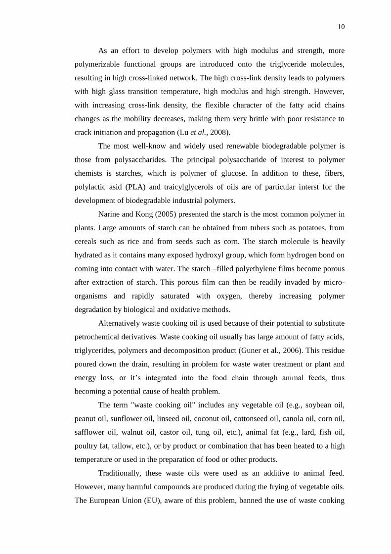
Fats and oils generally function in the latter capacity. Fats differ from oils
only in that they are solid at room temperature, while oils are liquid. Fats and oils
share a common molecular structure, which is represented in Figure 2.3.
Figure 2.3: Chemical structure of fats and oils (Shakhashiri, 2008).
This structural formula in Figure 2.4 shows that fats and oils contain three
ester functional groups which is tri-alcohol, glycerol (or glycerine). In the fatty acids,
Ra, Rb, and Rc, represent groups of carbon and hydrogen atoms in which the carbon
atoms are attached to each other in an unbranched chain (Shakhashiri, 2008).
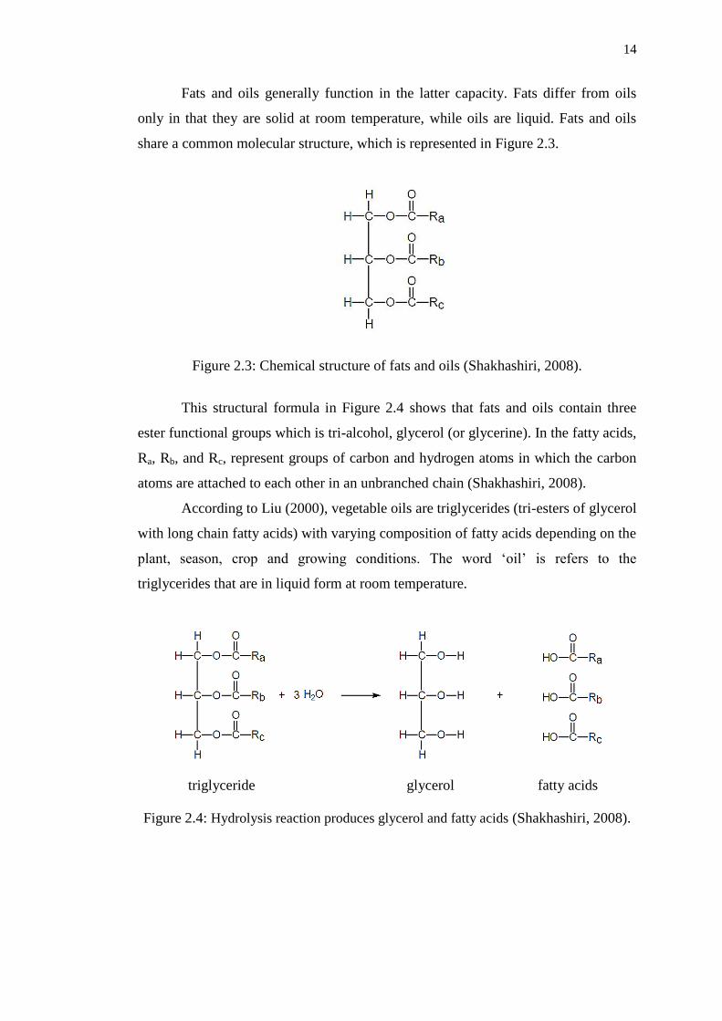
According to Liu (2000), vegetable oils are triglycerides (tri-esters of glycerol
with long chain fatty acids) with varying composition of fatty acids depending on the
plant, season, crop and growing conditions. The word „oil‟ is refers to the
triglycerides that are in liquid form at room temperature.
Figure 2.4: Hydrolysis reaction produces glycerol and fatty acids (Shakhashiri, 2008).
triglyceride glycerol fatty acids

15
However, their use as monomers presents challenges due to their
heterogeneous and variable structures. Indeed, it can be expensive to separate and
extract the different triglycerides present because the oils are typically expressed in
low concentrations and the composition of particular oil can vary seasonally. The key
chemical building blocks of vegetable oils are triglycerides: triesters of glycerin and
fatty acids as shown in Figure 2.5. Of the five commonly occurring fatty acids, two
are saturated (palmitic and stearic) and three are unsaturated (oleic, linoleic, and
linolenic) (Williams, et al., 2008).
Figure 2.5: The structure of triglycerides and the five most common fatty acid
substituents for vegetable oils (Williams et al., 2008)
Vegetable oils are one of the most abundant biological sources and important
raw materials for the production of bio-based polyurethanes because of their
numerous advantages: low toxicity, inherent biodegradability, and high purity. As a
result of the hydrophobic nature of triglycerides, vegetable oils produce
polyurethanes that have excellent chemical and physical properties such as enhanced
hydrolytic tendencies, high tensile strength and elongation, high tear strength, and
thermal stability (Oprea, 2010). On the other hand, these materials have relatively
low thermal stability, primarily due to the presence of urethane bonds. The onset of

16
urethane bond dissociation is somewhere between 150 °C and 220 °C, depending on
the type of substituents, on the isocyanate and polyol side. Saturated hydrocarbons
are known to have relatively good thermal and thermo-oxidative resistance compared
to polyether and polyester polyols derived from petrochemicals (Monteavaro, 2005).
In addition to these renewable resources, naturally occurring triacylglycerol
(TAG) oils are also significant starting materials for the production of biodegradable
polymers. Vegetable oils are abundant and widely available; they are relatively low
cost materials and offer a possibility of biodegradable. Polymer prepared from
vegetable oils has a number of excellent properties due to the hydrophobic nature of
triglycerides. On the other hand; these materials have relatively low thermal stability,
primarily due to the presence of urethane bond (Monteavaro, 2005).
They consist of triglyceride molecules that are esters of glycerol and fatty
acids, predominantly unsaturated fatty acids. These triglycerides present many
reactive sites able to be reacted in order to obtain a product for the polymer industry.
This is because triglycerides contain several reactive positions that are amenable to
chemical reactions: ester groups, C=C double bonds, allylic positions and the
position of ester groups.
Plant oils mainly consist of triacylglycerols (TAG), which can be processed
into high-value biochemical for various industries. In polymer application, the
conversion of oilseed crops into bioplastics could be a sustainable alternative which
could compete with plastics obtained from petroleum chemicals. It has been already
shown that polyurethane (PU) produced using vegetable oils such as soybean oil
present some excellent properties such as enhanced hydrolytic and thermal stability
(Bouzidi et al., 2007).
In recent years, extensive work has been done to develop polymers with
triglycerides of fatty acids as the main component. Raw materials from vegetable oils
are important sources for green polyols. As a matter of fact, vegetable oils have a
number of excellent properties which could be utilized in producing valuable
polymeric materials such as epoxy, polyesteramide, alkyd and polyurethane in
addition to their many applications in other areas. Other traditional seeds such as
linseed, soybean, amaranth, castor, sunflower kernels, cashew nut, and karanja have
been used or still under development for the synthesis of different kinds polymeric
resin (Velayuthama et al.,2009).

17
Renewable polymer is used to describe the complete mineralization of the
starting compound to simpler ones like CO2, H2O, NO3 and other inorganic
compounds (Nair, C, I., Jayachandran, K. & Shashidar, S. 2008). Renewable
polymer is governed by different factors that include polymer characteristics, type of
organism, and nature of pretreatment. The polymer characteristics such as its
mobility, tacticity, crystallinity, molecular weight, the type of functional groups and
substituents present in its structure, and plasticizers or additives added to the polymer
all play an important role in its degradation. During degradation the polymer is first
converted to its monomers, and then these monomers are mineralized. Most
polymers are too large to pass through cellular membranes, so they must first be
depolymerized to smaller monomers before they can be absorbed and biodegraded
within microbial cells. The initial breakdown of a polymer can result from a variety
of physical and biological forces. Physical forces, such as heating/cooling,
freezing/thawing, or wetting/drying, can cause mechanical damage such as the
cracking of polymeric materials. The growth of many fungi can also cause small-
scale swelling and bursting, as the fungi penetrate the polymer solids.
2.3 Formation of polymer foam
In producing and fabricating a good specimen for sound absorption, there is a need to
consider the properties of each material chosen, thus the effects on sound absorption
material to absorb most of the sound rather than to reflect the sound. There are some
materials required to produce sound absorption foam, polyurethane, such as flexible
isocyanate, polyol and titanium dioxide (TiO2). The characteristic of polyurethane
foam can be changes via adjusting the chemical composition of the raw materials, in
particular polyol and isocyanate in which the polyurethane properties mainly
depends on the types of polyol such as functionality and hydroxyl value (Lim and
Kim 2008).
The forming process of polyurethane foam consist three basic stages such as
bubble initiation, bubble growth and cell opening (Klempner and Sendijarevic,
2004). The bubble initiation was initially introduced by physically bending air into
the mixture. The bubble growth occurs when the gas diffused and expands the gas
phase due to increasing the temperature. The gas may originate from sources such as
a gas involved by water reaction, blowing agents, carbon dioxide and surfactant. The

18
heat generated during the reactions due to exothermic process play an important role
in expansion to form a cellular structure. The bubble continued to growth, it will
begin the cell opening to produce polyurethane foam.
Polyurethane (PU) foam is produced by one-shot and free rise method
(Klempner & Sendijarevic, 2004 and Sung et al., 2007). The one shot and free rise
means that the isocyanate, polyol, water and other ingredients are rapidly and
intensively mixed and immediately poured to carry out the foaming.
Generally, polyurethane (PU) foams are made via two types of fabrication
process which are molded and slab-stock foaming (Zhang, 2008). Moulded foams
are largely used in transportation application such as automotive seating whereas
slab-stock foams are used in furnishing industry such as mattress and carpet backing
(Zhang, 2008). For molded foams, the process begins by mixing all of the reactants
together and transferring the foaming mixture to a closed mold (Klempner &
Sendijarevic, 2004). The foams are then raised to take on the shape of the mold.
However, for slab-stock foams, the process is performed in an open environment
(Klempner & Sendijarevic, 2004). That is, the well-mixed reactants are spread onto
a conveyor belt, and as the conveyor belt moves forward, the foaming mixture
expands and rises to shape.
For the small or laboratory scale production, the polyurethane (PU) foams
could be made as a simple hand or cup-foam mixes to techniques of box-foaming
mixes according to Klempner & Sendijarevic (2004). In this process, the foam is
prepared as free-rise bun. It was noted that the production routes from many
laboratory scale foam composite fabrication are actually similar (Table 2.1). The
differences between all of the previous works were duration of the components to
mix and for the foams to cure. Table 2.1 lists the time consumed at each stage for
polyurethane (PU) foam composites production.

19
Table 2.1: Parameters used for flexible foam composites production
Year Author Preparation of Foam Foam Cured
2008 Sant'Anna et
al.
i. Polyol and fillers were stirred until completed
homogenization.
ii. Amine, surfactant, and water were added to
mixtures and mechanical stirred for 1 minute.
iii. Catalysts was added and stirred for 30 seconds.
iv. Isocyanate was introduced to mixtures and stirred
for 6 seconds.
The foams were
left to cured for
three days.
2009 Mello et al.
The foams were produced at room temperature.
i. Mechanical stirred the polyol and PET particles for
15seconds.
ii. The mixtures, water, silicone, catalysts, and
stannous octoate at 850 rpm were again stirred for 1
minute.
iii. Addition of isocyanate and methylene chloride to
the mixtures and stirred for 5 seconds.
After the foam
development,
the foam was
demould and
left to rest for
24 hours.
2009 Verdejo et al.
i. A fixed weight of carbon nanotube was mixed with
polyol at 2000 rpm for 10 minutes using an
overhead stirrer equipped with dispersion disc.
ii. The surfactant, catalyst, distilled water were added
to mixtures and mixed at 2000 rpm for 1 minute.
iii. Isocyanate was added and stirred for 15 seconds
before foaming occurred.
The foam in
mould is
transferred into
oven at 50°C
overnight and
demould.
2010 Latinwo., et al
i. The mixture of polyol with filler (calcium
carbonate) was added to the content of the mixing
chamber and stirred for 6 s.
ii. The surfactant, catalyst and water as the blowing
agent were added to the mixture the polyol and
filler in the mixing chamber and thoroughly
premixed.
iii. The isocyanate was weighed directly into this
mixture and the completed formulation was stirred
with an overhead mechanical mixer for 4 s.
iv. The foam was poured in open mould which was
treated with mould release agent to produce with
free-rise foam
After 10 min
the foams is
removed from
the mould and
left to cure for
at least 7 days

20
Table 2.1: (Continued)
2011 Ting et al.
i. The desired fumed silica was mixed with
isocyanate using a magnetic stirrer for 30 minutes.
ii. Polyol with catalyst, surfactant and blowing agent
contain were added into mixture and stirred at 500
rpm for 15 seconds.
The foams is
transferred into
an oven at 50°C
for 3 hours and
demould.
2012 Bernal et al.
i. The polyol and carbon nanofillers were stirred
using overhead stirrer equipped with dispersion
disc for 6 hours and 2400 rpm.
ii. The surfactant, catalysts, and distilled water were
added to mixtures and stirred at 2400 rpm for 3
minutes.
iii. Finally, isocyanate was added and mixed again for
20 seconds.
The foaming
process
occurred in an
open mould
2.3.1 Foam Formula and Generation
Foam is an important engineering material. It offers unique advantages in terms of
low cost and weight, easy to manufacture and has good energy absorption properties.
It is used in many applications; acoustic absorption, impact retardation and
mechanical damping (Singh et al., 2003 and Lee et al., 2007).
In most modern automotive seats, static comfort and vibration isolation are
now achieved through the use of foam alone. Polymer foams represent one of many
types of polymeric materials such as solid (nonporous), reinforced, laminated, etc.
Schematically in Table 2.2, all types of polymer foam can be classified in three
generations and each type of foam has different technical characteristics and also
different cellular structure (Klempner and Sendijarevic, 2004).

21
Table 2.2: Three generation of polymer foams
Generation Type of Foam
First Generation:
1940-1970
Isotropic foams
Sandwich structures
Second Generation:
1970-1985
Structural (Integral) foams
Syntactic foams
Reinforced and filled foams
Foamed laminates
RIM and RRIM foams
Microcellular foams
Third Generation:
1985 until present
One-sided structural foams
Inverse structural foams
Syntactic - structural foams
Foamed syntactic foams
Foamed fibres and films
Macro/Micro (bi – modal) fomas
Foam-in Foam structure
Nano foams
Basically, polyurethane (PU) foam is made from a formula that contains a
host of ingredients selected to aim in achieving the desired grade of foam. These
components included polyol, isocyanate, water, catalysts, surfactants, cross-linkage
agent, auxiliary blowing agent, and additives such as colorant, flame retardant,
antistatic agent, bacteriostat or UV stabilizer. Among all, polyol and isocyanate are
the main components used to forms polyurethane linkage (Figure 2.6).
Figure 2.6: Gelation reaction or PU cross-linkage reaction (Kaushiva, 1999)
The reaction between polyol and isocyanate is called gelation reaction
(Kaushiva, 1999). It is an exothermic process for which heat of reaction had been
reported approximately 24 kcal/mol of urethane (Klempner & Sendijarevic, 2004).
H H H
Isocyanate Alcohol Urethane

22
There is another reaction occurred during foam generation. It is called blow reaction
(Kaushiva, 1999).
Figure 2.7: Blow reaction between isocyanate and water (Kaushiva, 1999)
Figure 2.7 illustrates the blow reaction generation. In this reaction, water
reacts with isocyanate to produce carbon dioxide (CO2) which diffuses to the existing
gas bubbles in the polyol and so expands the foam. It was reported that the internal
temperature of foam bun/rise would build up on the order of 140 °C during foam
generation (Klempner & Sendijarevic, 2004)
Other components in formula are working as: surfactants are necessary
components in foam formation in order to produce a well open-celled morphology.
They perform to reduce surface tension in polyurethane, emulsifying incompatible
ingredients, promoting bubble nucleation, stabilizing the rising foam, thus reducing
the deformation effect and the most important is to stabilise the cell wall.
As reported by Klempner & Sendijarevic (2004), surfactant prevents the
coalescence of rapidly growing cells until those cells have attained sufficient strength
through polymerization to become self supporting. Without this, cell coalescence
would lead to a total foam collapse. Catalysts are generally used in foam formulation
for establishing a balance between the chain propagation in of gelation reaction and
blow reaction (Klempner & Sendijarevic, 2004). Besides, it is also for assuring
completeness of reaction or “cure” in finished foam (Klempner & Sendijarevic,
2004).
There are three basic stages found in foam foaming process. They are bubble
initiation, bubble growth, and cell opening (Klempner & Sendijarevic, 2004). Figure
2.8 illustrates the development and formation of a polyurethane (PU) foam in an
open-mould. The first stage is the bubble initiation of foam is started by introducing
the physical blending air into the mixture. This could be done by using a high shear
H
Isocyanate Water Carbon
Dioxide
Carbamide
Acid
Amine

23
mixing machine or a stirring device that works in a certain rotational speed for
entrance of enough bubbles to account for all of the cells present in the PU foam
(Latinwo et al., 2010a and Zhang et al., 2011).
The second stage is called bubble growth. This occurs when the gas diffuses
and expands the gas phase due to the increase in foaming temperature. The gas may
originate from sources such as gas evolved by water reaction, as the gas dissolves in
the liquid reactant, auxiliary blowing agents vaporizes and gas evolves by thermal
decomposition of additives or components (Kaushiva, 1999). According to the
Figure 2.4, the gas diffuses to bubbles which is carbon dioxide (CO2). The heat
generated during the reactions (exothermic process) play an important role in
expansion for example CO2 to form a cellular structure.
TIME
PHYSICAL
EVENTS
KINETIC
EVENTS
MORPHOLOGY
EVENTS
Figure 2.8: Development of polyurethane (PU) foam (Klempner & Sendijarevic,
2004)
Air
Polyol,
Water,
Additive
Isocyanate
Raw
Materials
Mixing &
Bubble
Nucleation
Cream &
Initial
Rise
Rising
Foam
Blow off
and
Gelation
Cure
0 10 30-90 Hours To
Seconds Seconds Days
Bubbles
Formed
Bubbles
Grow
Color
Change
Viscosity
Increase
Cell Opening
Modulus Growth
IFD
Spread
Collisional Water React.
Polyol
React. Diffusional
CO2 Sat. Mol. Wt.
Increase
Homogeneous
Mixture
Two-Phase
System Morphology Set
Monomer
Begin
Reacting
Urea and
Urethane
Segment
Grow
Solid-Liquid
Phase
Separation
Verification
at
Berghman‟s
Point
Network
Ripens

24
It was noted that as bubbles continued to grow, it will begin to impede with
each other in the foam system (Kaushiva, 1999). At this time, the solid phase of
matrix is forced to distribute itself around and form as lamellae and plateau borders
in between the cells.
This solid phase can be referred to the Figure 2.9 which illustrates the
morphology of cured polyurethane (PU) foam. From this figure, there is a
polyhedrons development inside foam (Kaushiva, 1999). It was reported that the
bubbles packaging during foam rising is very incontrollable (Kaushiva, 1999).
Hence, the cellular-structure of foam may shows anisotropic. Gibson & Ashby
(1997) mentioned that almost all man-made foams are anisotropic.
Figure 2.9: Morphology of polyurethane (PU) foam (Klempner & Sendijarevic,
2004)
In the third stage which is the cell opening, closed cells started to open when
one or more bubbles rupture. These ruptures are actually caused by excessive
thinning of lamellae which could not withstand the pressure in the cell. Struts are
formed once the lamellae of closed cell rupture. At the end, the open-celled
polyurethane (PU) foam is obtained once the foam finish is cured. However, it is not
easy to obtain well open-celled foam due to problems like blowing agents escape in
close cells, which may result in the cells remaining closed at all the time (Kaushiva,
1999).
In order to produce well open-celled foams, there are two critical elements to
meet, which are adjustment of (i) the rate of foaming, and (ii) the rate of
Plateau
Borders
Closed Window (Lamellae) Struts
Open
Window
Cells