aci structural journal technical paper - …sites.utoronto.ca/sheikh/sheikhpapers final...
TRANSCRIPT
ACI Structural Journal/July-August 2002 451
ACI Structural Journal, V. 99, No. 4, July-August 2002.MS No. 01-289 received September 12, 2001, and reviewed under Institute publica-
tion policies. Copyright © 2002, American Concrete Institute. All rights reserved,including the making of copies unless permission is obtained from the copyright pro-prietors. Pertinent discussion will be published in the May-June 2003 ACI StructuralJournal if received by January 1, 2003.
ACI STRUCTURAL JOURNAL TECHNICAL PAPER
Damage sustained by foundation walls and large beams in a build-ing was simulated in full-size to near-full-scale model specimens inthe laboratory. The damaged specimens were repaired with carbonand glass fiber-reinforced polymer (CFRP and GFRP) sheets andwraps, and tested to failure. Companion control specimens werealso tested to failure without rehabilitation to provide a basis forcomparison and evaluate the effectiveness of the repair techniques.Test results showed that fiber-reinforced polymers (FRPs) wereeffective in strengthening for flexure as well as shear. Over-reinforcing in flexure resulted in shifting the failure to shearmode, which in some cases may be undesirable. Strengthening of amember in shear, on the other hand, resulted in increasing the ultimatedisplacement by more than tenfold, and toughness by a factor of morethan 26. Available analytical procedures and building code provisionswere found to simulate the behavior of specimens retrofitted withFRP reasonably well.
Keywords: fibers; flexure; polymer; shear.
INTRODUCTIONThe upgrading of existing structures is an integral part of
structural engineering practice and requires a dedicated solu-tion to a problem at hand. Retrofitting may be required tostrengthen the structures either damaged by environmentaleffects or that need to meet new code requirements. Thereare always design- and construction-related deficiencies thatneed to be corrected. Steel and cementitious materials arecommonly employed for most of the retrofitting work, butthey have not always proved effective, durable, or economical.Due to the heavy weight of the materials, these techniques areequipment- and labor-intensive. The duration of repair mayalso be quite long, often requiring the facility to close for along period of time, which could be very costly. In the caseof bridges and other transportation structures, the duration ofrepair time is a particularly critical factor in the decision-making process. In many situations, retrofitting with fiber-reinforced polymers (FRPs) provides a more economical andtechnically superior alternative to traditional techniques.FRPs are lighter, durable, and have higher strength-to-weightratios than traditional materials such as steel. Working withFRP is, therefore, less labor- and equipment-intensive, whichcan shorten the time required for retrofitting and allow theconstruction to proceed without closing the facility.
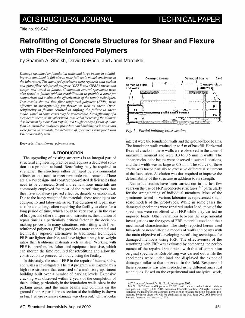
In this study, the use of FRP in the repair of beams, slabs,and walls is investigated. The test program was inspired by ahigh-rise structure that consisted of a multistory apartmentbuilding built over a number of parking levels. Extensivecracking was observed within 2 years of the completion ofthe building, particularly in the foundation walls, slabs in theparking areas, and the main beams and columns on theground floor. A partial cross section of the building is shownin Fig. 1 where extensive damage was observed.1 Of particular
interest were the foundation walls and the ground-floor beams.The foundation walls retained up to 5 m of backfill. Horizontalflexural cracks in these walls were observed in the zone ofmaximum moment and were 0.3 to 0.5 mm in width. Theshear cracks in the beams were observed at several locations,and their width was as large as 0.8 mm. The source of thesecracks was traced partially to excessive differential settlementof the foundation. A solution was thus required to improve thedeformability of the structure in addition to its strength.
Numerous studies have been carried out in the last fewyears on the use of FRP in concrete structures,2-7 particularlyfor the strengthening of individual members. Most of thespecimens tested in various laboratories represented small-scale models of the prototypes. While in some cases thedamaged specimens were repaired under load, most of thespecimens were retrofitted with FRP while they carried noimposed loads. Other variations between the experimentalinvestigations are the types of FRP materials used and theirmechanical characteristics. The study reported herein usedfull-scale or near-full-scale models of walls and beams withthe main objective of developing retrofitting techniques fordamaged members using FRP. The effectiveness of theretrofitting with FRP was evaluated by comparing the perfor-mance of the repaired specimens with that of companionoriginal specimens. Retrofitting was carried out while thespecimens were under load and displayed the extent ofdamage similar to that observed in the field. Response ofthese specimens was also predicted using different analyticaltechniques. Based on the experimental and analytical work,
Title no. 99-S47
Retrofitting of Concrete Structures for Shear and Flexure with Fiber-Reinforced Polymersby Shamim A. Sheikh, David DeRose, and Jamil Mardukhi
Fig. 1—Partial building cross section.

ACI Structural Journal/July-August 2002452
retrofitting schemes were designed for various componentsof the building structure.
EXPERIMENTAL PROGRAMThree wall-slab specimens and two beam specimens were
constructed and tested. The three slab specimens were casttogether and each beam was cast separately.
Wall-slab specimensEach of the wall-slab specimens was 250 mm thick, 1200 mm
wide, and 2.1 m long, representing a full-scale model of thefoundation wall. Reinforcement in the direction of spanconsisted of four 10M (100 mm2) bottom bars and three10M top bars. Transverse reinforcement was provided byfive 10M top-and-bottom bars. Small steel plates (40 x 25 mm)were welded to the ends of the longitudinal bars to ensureanchorage. All dimensions and reinforcement detailingare provided in Fig. 2. Each wall-slab specimen was instru-mented with 15 electric strain gages on the longitudinal bars.The location of gages are also shown in Fig. 2. Due to roughtimber formwork, the bottom surfaces of the specimens wereuneven. Because two of the three specimens were to be repairedwith FRP, it was decided to grind the bottom surfaces to yielda smooth, clean surface that would ensure a good bond betweenthe concrete and the FRP.
Beam specimensFigure 3 shows the dimensions and reinforcement details
of the beam specimens in which the test section was 1000 mmdeep and 550 mm wide, a 5/6th-scale simulation of thebeams in the building. The beam was scaled down slightlyto accommodate construction in the laboratory. Thebeams in the building were framed into walls. This wassimulated by building a haunched region and increasingthe amount of reinforcement for that half of the beam. Asa result, shear failure was expected in the shallower part ofthe beam (Section B-B in Fig. 3), similar to what has beenobserved in the field.
Each beam specimen contained 21 electric strain gagesinstalled on the longitudinal and transverse steel. The locationsof these gages are also shown in Fig. 3. The wooden frameworkwas prepared to cast one specimen at a time. The casting wascarried out in two steps. In the first step, the beam was castwithout the haunch. Soon after casting, the specimen wascovered with moist burlap and polyethylene sheeting for3 days. At this point, the additional formwork was built tocast the haunched portion. The surface of the existing concreteat the cold joint was roughened before the new concrete wasplaced. Once again, the specimen was cured with wet burlapand polyethylene sheeting for 3 days after casting. Eightcylinders were also cast for each specimen to providecompressive strength data.
ConcreteReady-mixed concrete with a specified compressive
strength of 30 MPa and 20 mm maximum-size coarse aggregatewas used. The strength of concrete in the wall-slab specimensvaried between 48.4 and 53.9 MPa, while in the two beamspecimens, the strength was 44.7 and 45.7 MPa.
Shamim A. Sheikh, FACI, is a professor of civil engineering at the University ofToronto, Toronto, Ontario, Canada. He currently chairs Joint ACI-ASCE Committee441, Reinforced Concrete Columns, and is a member of ACI Committee 374, Performance-Based Seismic Design of Concrete Buildings. In 1999, he received the ACI StructuralResearch Award for a paper on the design of ductile concrete columns. His researchinterests include earthquake resistance and seismic upgrade of concrete structures,confinement of concrete, use of fiber-reinforced polymer in concrete structures, andexpansive cement and its applications.
David DeRose is involved in the new design and restoration of building enclosures atHalsall Associates Ltd. in Toronto. He received his MASc in civil engineering in 1997from the University of Toronto. His research interests include retrofitting with fiber-reinforced polymers.
ACI member Jamil Mardukhi is a principal of NCK Engineering, Ltd., Toronto. Hisresearch interests include design and construction of special structures.
Fig. 2—Wall-slab specimen details.
Fig. 3—Beam specimen details.

ACI Structural Journal/July-August 2002 453
SteelDeformed bars were used in all the specimens. U.S. No. 3
(71 mm2) bars were of Grade 60 steel, while Grade 400 steelwas used for Canadian sizes 10M, 25M, and 30M (100, 500,and 700 mm2). Figure 4 shows the stress-strain curves for thesteel bars used in the test program. Each curve represents theaverage of a minimum of three tension tests.
Fiber-reinforced polymerA commercially available FRP system was used for repairing
the beam and wall-slab specimens. Two types of fabrics wereused in this study. The glass fabric was nominally 1.25 mmthick, and the carbon fabric was designated as 1.0 mmthick. The test coupons for FRP were made from the fabricimpregnated with epoxy and cured to harden. Two typesof epoxies were used in the test; one of these was more viscousthan the other. Each epoxy consisted of two components, A andB, that were mixed for 5 min. with a mixer at a speed of 400to 600 rpm. Details of the test coupons and the load-straincurves for the two types of FRP are shown in Fig. 5. Eachcurve is an average of at least three tests. Because the thicknessof the composite specimen depends on the amount of epoxyused, the tensile strength is represented in force per unitwidth instead of force per unit area, that is, stress.
TESTINGWall-slab specimens
The three wall-slab specimens were tested under deformationcontrol in a 2700 kN universal testing machine. Two line loadswere applied to the specimens to produce flexural crackingsimilar to that observed in the field. The loading, supportconditions, and the external instrumentation are shown in Fig. 6.Two curvature meters and three linear variable differentialtransducers (LVDTs) were used to obtain information aboutdeformations during loading in addition to the strain gagesinstalled on the steel cages. The cracks, as they developedunder load, were also monitored in specimen Wall1 to deter-mine the point at which the other two specimens (Wall2 andWall3) would be repaired. Specimen Wall1 failed in flexureat a total load of 193 kN (Fig. 7).
Specimen Wall2 was to be rehabilitated with the carbonfabric. This specimen was initially loaded to 135 kN. Theaverage strain at the center of the bottom flexural steelwas 3.3 × 10⁻³ at this stage. Two flexural cracks had formedat this load. The crack width at various locations varied
between 0.3 and 0.7 mm at the bottom of the slab with anaverage width of approximately 0.4 mm. These crackswere similar to those measured in the field. As a result, thedisplacement was maintained at the level while the repairwas carried out by the supplier of the FRP composite material.All external instrumentation was removed to apply the fabric.
For the application of FRP to the underside of the slab, twotypes of epoxies were used as discussed previously. Themore-viscous epoxy was applied directly to the concretesurface. This tacky coat of epoxy was essential to ensurethat the fabric would adhere to the underside of the slab. Thecarbon fabric was saturated with the less-viscous (regular)
Fig. 4—Tensile stress-strain characteristics of steel.Fig. 5—Tensile load-strain behavior of FRP.
Fig. 6—Loading and support conditions for wall-slabspecimens.
Fig. 7—Specimen Wall1 after failure.

454 ACI Structural Journal/July-August 2002
epoxy prior to its application to the slab surface. Three stripsof fabric, approximately 600 mm in width, were used asshown in Fig. 8. The outer strips of fabric were folded up andbonded to the sides of the specimen. Previous research5 hadshown that this provided an effective anchorage in beams toeliminate premature FRP separation from concrete. In thefield, sufficient anchorage length was available to developfull strength of FRP. The epoxy was allowed to cure for 3 daysbefore the repaired specimen was tested. During the time ofrepair and curing, the load fell to approximately 115 kNunder constant displacement mode of the testing machine.At this time, the external instrumentation was reapplied, andthe load was increased until the specimen was damaged
extensively. The specimen failed in shear with large inclinedcracks and delamination of CFRP (Fig. 9). The maximumload carried by the specimen was 478 kN.
The third specimen (Wall3) was tested the same way asWall2, except that glass FRP (GFRP) was used for repair.The behavior of Wall3 was similar to that of Wall2, but thefailure load was smaller. Shear failure occurred at the appliedload of 422 kN.
Beam specimensBoth the beams were tested using a hydraulic jack connected
to a rigid, 5400 kN testing machine frame. A load cell connectedto the data acquisition system was used to measure the appliedload. A single-point load was applied on the haunchedportion (Fig. 10) to test the beam and produce crackingsimilar to that encountered in the field. External instrumenta-tion, shown in Fig. 10, was used to obtain information about theshear strain and the deflection profile as the test progressed.
The first specimen, Beam1, was considered as a controlspecimen against which the performance of FRP-retrofittedbeam was to be measured. Figure 11 shows the testedBeam1. As the load was increased, several shear cracksappeared that were monitored to determine the similarityof distress between the specimen and the beams in the building.At a load of approximately 1000 kN, extensive shear crackingwas observed, with the maximum crack width equal to0.75 mm. As the load increased to 1600 kN, the crackwidths exceeded 2.0 mm, and the beam failed in a brittlemanner at a load of 1700 kN. This mode of failure is typicalof large beams that are shear-critical and contain very lightshear reinforcement.
In addition to providing information about the safety of thebeam in the field, the crack monitoring also helped identifythe point at which the second beam specimen would beretrofitted with CFRP. The haunched region of the secondbeam was strengthened in shear by using a clamp consistingof steel beams and steel bars. This was done to ensure thatthis portion of the beam would not fail in shear after therepair of the test region had taken place.
Beam2 was loaded to 1180 kN when five diagonal cracks,ranging in width from 0.2 to 0.8 mm, were observed. Theaverage strain at the center of the bottom flexural steelwas approximately 1.5 × 10⁻³ at this stage. The crack patternand the crack widths appeared similar to what was observed inthe beams of the building. As a result, the displacement imposed
Fig. 8—Application of FRP on wall-slab specimens.
Fig. 9—Specimen Wall2 after failure.
Fig. 10—Loading and support conditions for beam specimens.
Fig. 11—Specimen Beam1 after failure.
ACI Structural Journal/July-August 2002 455
on the beam was maintained while the repair procedure wasinitiated by first removing all the external instrumentation.
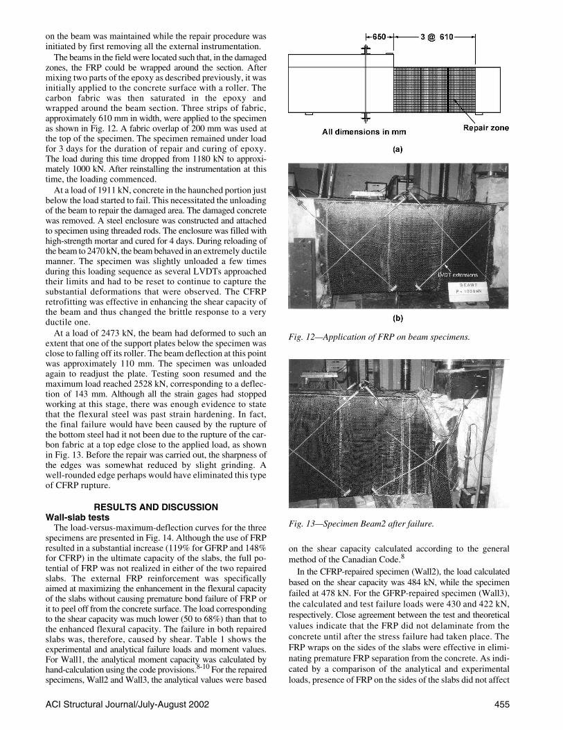
The beams in the field were located such that, in the damagedzones, the FRP could be wrapped around the section. Aftermixing two parts of the epoxy as described previously, it wasinitially applied to the concrete surface with a roller. Thecarbon fabric was then saturated in the epoxy andwrapped around the beam section. Three strips of fabric,approximately 610 mm in width, were applied to the specimenas shown in Fig. 12. A fabric overlap of 200 mm was used atthe top of the specimen. The specimen remained under loadfor 3 days for the duration of repair and curing of epoxy.The load during this time dropped from 1180 kN to approxi-mately 1000 kN. After reinstalling the instrumentation at thistime, the loading commenced.
At a load of 1911 kN, concrete in the haunched portion justbelow the load started to fail. This necessitated the unloadingof the beam to repair the damaged area. The damaged concretewas removed. A steel enclosure was constructed and attachedto specimen using threaded rods. The enclosure was filled withhigh-strength mortar and cured for 4 days. During reloading ofthe beam to 2470 kN, the beam behaved in an extremely ductilemanner. The specimen was slightly unloaded a few timesduring this loading sequence as several LVDTs approachedtheir limits and had to be reset to continue to capture thesubstantial deformations that were observed. The CFRPretrofitting was effective in enhancing the shear capacity ofthe beam and thus changed the brittle response to a veryductile one.
At a load of 2473 kN, the beam had deformed to such anextent that one of the support plates below the specimen wasclose to falling off its roller. The beam deflection at this pointwas approximately 110 mm. The specimen was unloadedagain to readjust the plate. Testing soon resumed and themaximum load reached 2528 kN, corresponding to a deflec-tion of 143 mm. Although all the strain gages had stoppedworking at this stage, there was enough evidence to statethat the flexural steel was past strain hardening. In fact,the final failure would have been caused by the rupture ofthe bottom steel had it not been due to the rupture of the car-bon fabric at a top edge close to the applied load, as shownin Fig. 13. Before the repair was carried out, the sharpness ofthe edges was somewhat reduced by slight grinding. Awell-rounded edge perhaps would have eliminated this typeof CFRP rupture.
RESULTS AND DISCUSSIONWall-slab tests
The load-versus-maximum-deflection curves for the threespecimens are presented in Fig. 14. Although the use of FRPresulted in a substantial increase (119% for GFRP and 148%for CFRP) in the ultimate capacity of the slabs, the full po-tential of FRP was not realized in either of the two repairedslabs. The external FRP reinforcement was specificallyaimed at maximizing the enhancement in the flexural capacityof the slabs without causing premature bond failure of FRP orit to peel off from the concrete surface. The load correspondingto the shear capacity was much lower (50 to 68%) than that tothe enhanced flexural capacity. The failure in both repairedslabs was, therefore, caused by shear. Table 1 shows theexperimental and analytical failure loads and moment values.For Wall1, the analytical moment capacity was calculated byhand-calculation using the code provisions.8-10 For the repairedspecimens, Wall2 and Wall3, the analytical values were based
on the shear capacity calculated according to the generalmethod of the Canadian Code.8
In the CFRP-repaired specimen (Wall2), the load calculatedbased on the shear capacity was 484 kN, while the specimenfailed at 478 kN. For the GFRP-repaired specimen (Wall3),the calculated and test failure loads were 430 and 422 kN,respectively. Close agreement between the test and theoreticalvalues indicate that the FRP did not delaminate from theconcrete until after the stress failure had taken place. TheFRP wraps on the sides of the slabs were effective in elimi-nating premature FRP separation from the concrete. As indi-cated by a comparison of the analytical and experimentalloads, presence of FRP on the sides of the slabs did not affect
Fig. 12—Application of FRP on beam specimens.
Fig. 13—Specimen Beam2 after failure.

456 ACI Structural Journal/July-August 2002
their mechanical behavior. The repair procedure restored thestiffness values of the slabs to that of the original, undamagedspecimen (Fig. 14). The response of both the repairedspecimens was reasonably ductile and resulted in a largeenergy dissipation, though not as ductile as the controlspecimen. The GFRP-repaired specimen showed higherductility than the CFRP-repaired specimen. If higher ductility,rather than the strength, is desired, a lesser amount of FRPreinforcement than that used in the tests should be applied.
From the available analytical procedures based on straincompatibility, the moment-curvature responses of the threewall-slab specimens were developed. The Hognestad paraboliccurve for the concrete stress-strain curve was used alongwith the steel and FRP properties shown in Fig. 4 and 5,respectively. In addition to hand-calculations, a computerprogram developed at the University of Toronto, RESPONSE,9,11
was used to calculate the analytical response. For Wall1, hand-calculations were performed without tension-stiffeningeffects, with a tension-stiffening factor of 0.5. As shown inFig. 15, the yield and the ultimate moment capacities are betterpredicted by ignoring the tension-stiffening factor. RESPONSE
adjusts the effect of tension stiffening based on the informa-tion provided about the section. For the control specimen,the analytical responses match the experimental behaviorvery well.
In the repaired specimens, the initial curvature at the timeof repair was considered in the analysis by allowing for theinitial strains in the slab section. The strain in the bottom ofthe slab section thus became the locked-in strain differencebetween the concrete and FRP. Typical strain profiles encoun-tered in the analysis have also been included in Fig. 15.RESPONSE allows the user to enter initial strains. As a result, twoanalyses were performed for each repaired specimen: the firstup to the repair point; and the second after the repair, consid-ering initial strain and addition of FRP. The analytical curvesfrom RESPONSE shown in Fig. 15 are the curves obtainedfrom merging the results from the two analyses. The initial
Table 1—Load and moment values at failure in wall-slab specimens
Specimen
Experimental Analytical
Failure modeLoad, kN
Moment, kN-m Load, kN
Moment, kN-m
Wall1 193 62.7 182 59.1 Flexure
Wall2 478 155.4 484 157.3 Shear
Wall3 422 137.2 430 139.8 Shear
Fig. 14—Load-deflection behavior of wall-slab specimens.
Fig. 15—Experimental and predicted responses of wall-slabspecimens.

ACI Structural Journal/July-August 2002 457
experimental behavior of the GFRP-retrofitted wall-slabspecimen (Wall3) was somewhat stiffer than predicted,which may be the result of a lower-than-actual stiffness valueused for GFRP in the analysis. Overall analytical curves,however, predict the behavior reasonably well up to thefailure of the specimen when both the specimens failed inshear. The analytical curves are shown to a point where aquick drop in load was observed. The moment values corre-sponding to the shear capacity, predicted by the generalmethod of the Canadian Code,8 are given in Table 1. It can beconcluded that the available techniques with appropriate materialproperties can be used to evaluate the performance of slabsrepaired in flexure with FRP.
Beam testsThe load-deflection curves for the two beams are shown in
Fig. 16. While Beam1 failed in shear at a load of 1700 kN,Beam2, retrofitted with CFRP, had an ultimate capacity of2528 kN and failed in flexure. The maximum deflection atfailure in the original beam was 14 mm under the load point,which increased to 143 mm in the repaired beam. The repairedbeam was retrofitted with CFRP for shear resistance under aload of 1180 kN when the maximum beam deflection wasless than 8 mm. The energy dissipation capacity, or thetoughness, of the repaired beam was more than 2600% ofthat of the original beam.
The failure load for the control beam, based on the shearcapacity calculated from the Canadian Code,8 was between1095 kN (simplified method) and 1167 kN (general method).The beam capacity calculated from the ACI code10 equationsis 1561 kN. Load estimates from both the codes wereconservative, as the shear failure of the beam occurred at aload of 1700 kN.
The shear span-depth ratio of the beam was approximatelyequal to 2.0, which may have contributed to the developmentof compression struts after significant cracking had occurred.9
This may have contributed to the larger shear capacity observedin the test. The capacity based on the modified compressionfield theory was calculated to be 1710 kN,12 which isreasonably close to the test value.
For the application of code equations to predict the shearcapacity of the repaired beam, the carbon fabric was consid-ered as a series of equivalent stirrups. The total failure load,based on the general method of the Canadian Code,8 was5245 kN. The predicted failure load, based on shear capacityaccording to the simplified method of the Canadian Codeand the ACI Code,10 was 4985 kN. The beam, however,failed in flexure at a load of 2528 kN. The moment-curvatureresponse of the beam section subjected to the maximummoment is shown in Fig. 17 along with the behavior obtainedfrom the test. The two curves agree quite well. It shouldbe noted that the analytical moment-curvature response,shown in Fig. 17, is for a steel-reinforced section and isunaffected by the presence of FRP. As mentioned previ-ously, retrofitting was required to enhance strength aswell as deformability of the structure. The FRP wraps thatwere wrapped around the section not only increased the shearcapacity of the beam, but also enhanced the deformationcapacity of the concrete in compression, resulting in largeflexural ductility. In situations where complete wrapping of asection is not possible, the bonding between concrete and FRPmust be ensured to obtain strength enhancement.
Figure 18 shows the shear force-shear strain response of asection approximately 475 mm from the load application
point in Beam1, as obtained from the test. A similar behaviorwas also measured for a section 1675 mm from the load pointin the test region of the beam. This section was at the inter-section of one set of the diagonal LVDTs used to calculatethe shear strain. Analytical behavior curve using RESPONSE forthis section is also shown in Fig. 18. The initial portion of themeasured and predicted curves match quite well. The predictedshear capacity of less than 600 kN, however, is considerablylower than the measured capacity of 805 kN. A compressivestrut may have formed that influenced the behavior aftersubstantial cracking had occurred. Predicted and measuredshear capacities were similar at a section 1675 mm awayfrom the load.
Measured and predicted shear plots for the repairedspecimens are shown in Fig. 19 for a section approximately475 mm from the load point. An analytical curve obtainedfrom RESPONSE provided a reasonably accurate simulation ofthe section’s behavior. The carbon wrap prevented thewidening of shear cracks, which allowed the concretecontribution to shear resistance to be maintained. With addi-tional shear capacity from CFRP, the beam was able to developfull flexural capacity and large deformation before failure.Although the fabric ruptured at a corner initiating the finalfailure of the beam, it can be argued that this may have beentriggered by very large flexural deformations.
Fig. 16—Load-deflection behavior of beam specimens.
Fig. 17—Experimental and predicted responses of specimenBeam2.

ACI Structural Journal/July-August 2002458
SUMMARY AND CONCLUSIONSThe structural distress encountered at various locations in
a multistory building was simulated in near full-scale specimensin the laboratory. Specimens were damaged to the same degreeas the prototype structural members in the field, and therepair was carried out under load using CFRPs andGFRPs. The repaired specimens were tested to failure.Companion control specimens were also tested to failurewithout rehabilitation to provide a basis for comparisonand evaluate the effectiveness of the repair techniques.Because the damage to the building was partly caused byexcessive differential foundation settlement, enhancement inductility was one of the main focuses in designing the retro-fitting schemes, particularly in the case of beams showingsigns of failure in shear. Another factor in the selection of therepair technique was the continued use of the structure fornormal activities.
The experimental program included testing of three wall-slabspecimens and two beams. The wall-slab specimens were250 mm thick, 1200 mm wide, and 1.2 m long, and the beamswere 550 mm wide, 1000 mm deep, and 4.8 m long. Variousanalytical techniques were used to simulate experimentalbehavior of the specimens. The following conclusions can bedrawn from the study.
Retrofitting with FRPs provides a feasible rehabilitationtechniques for wall-slabs and beams. FRPs were effective inenhancing strength in both flexure and shear. No prematuredelamination of FRP was observed in the test specimens.Both carbon and glass composites provided significantenhancement (more than 148%) in flexural strength to theextent that the failure of the wall-slab specimens shifted toshear mode which, in some cases, may not be acceptable. Ifneeded, the shear failure can be avoided by limiting theflexural strength enhancement—achieved by limiting theamount of FRP used. This will allow a more-efficient use ofFRP and result in a more-ductile behavior.
The wrapping of the beam of section size 550 x 1000 mmwith one layer of CFRP resulted in changing the brittle modeof shear failure at 1700 kN to a very ductile flexure failure at2528 kN. The deflection at failure increased from 14 mm inthe control specimen, to 143 mm in the retrofitted specimen.The theoretical failure load for the retrofitted beam based onits shear capacity was approximately 5000 kN.
The available analytical techniques provided reasonablesimulations of the behavior of the specimens retrofitted with
CFRP and GFRP. Provisions of the Canadian and ACI buildingcodes8,10 were found to provide reasonable estimates ofthe capacities for the retrofitted specimens.
ACKNOWLEDGMENTSThe experimental work reported herein was conducted with the financial
assistance from the Natural Sciences and Engineering Research Councilunder Grant No. STR 195771. The tests were conducted in the StructuresLaboratories at the University of Toronto. Technical and financial assistancefrom R. J. Watson, Inc., of East Amherst, N.Y., Fyfe Co. of San Diego,Calif., and RoadSavers Central Ltd. of Toronto, is gratefully acknowledged.
REFERENCES1. DeRose, D., and Sheikh, S.A., “Rehabilitation of a Concrete Structure
using Fibre-Reinforced Plastics,” Research Report, Department of CivilEngineering, University of Toronto, Toronto, Ontario, Canada, 1997, 170 pp.
2. Mufti, A. A.; Erki, M.; and Jaeger, L. G., Advanced CompositeMaterials with Applications to Bridges, Canadian Society of CivilEngineering, 1991, 297 pp.
3. Meier, U., and Kaiser, H., “Strengthening of Structures with CFRPLaminates,” Advanced Composite Materials in Civil Engineering Struc-tures, Proceedings of the Speciality Conference, Las Vegas, Nev., ASCE,Jan. 31-Feb. 1, 1991, pp. 288-301.
4. Saadatmanesh, H., and Ehsani, M., “RC Beams Strengthened withGFRP Plates: Part I and Part II,” Journal of Structural Engineering, ASCE,V. 117, No. 11, 1991, pp. 3417-3455.
5. Sharif, A.; Al-Sulaimani, G. J.; Basunbul, I. A.; Baluch, M. H.; and Bhaleb,B.N., “Strengthening of Initially Loaded Reinforced Concrete Beams using FRPPlates, ACI Structural Journal, V. 91, No. 2, Mar.-Apr. 1994, pp. 160-168.
6. Fam, A. Z., and Rizkalla, S. H., “Behavior of Axially Loaded Con-crete-Filled Circular Fiber-Reinforced Polymer Tubes,” ACI StructuralJournal, V. 98, No. 3, May-June 2001, pp. 280-289.
7. Shahawy, M.; Chaallal, O.; Beitelman, T. E.; and El-Saad, A., “FlexuralStrengthening with Carbon Fiber-Reinforced Polymer Composites ofPreloaded Full-Scale Girders,” ACI Structural Journal, V. 98, No. 5, Sept.-Oct. 2001, pp. 735-743.
8. “Code for the Design of Concrete Structures for Building (CAN3-A23.3 M94),” Canadian Standards Association, Rexdale, Ontario, Canada,1994, 199 pp.
9. Collins, M. P., and Mitchell, D., Prestressed Concrete Basics, Cana-dian Prestressed Concrete Institute, 161 pp.
10. ACI Committee 318, “Building Code Requirements for StructuralConcrete (ACI 318-99) and Commentary (318R-99),” American ConcreteInstitute, Farmington Hills, Mich., 1999, 391 pp.
11. Bentz, E., “Sectional Analysis of Reinforced Concrete Members,”PhD thesis, Department of Civil Engineering, University of Toronto, Tor-onto, Ontario, Canada, Jan. 2000, 310 pp.
12. Sheikh, S. A.; Vecchio, F. J.; DeRose, D.; and Bucci, F., “Behaviorand Analysis of FRP-Repaired Elements,” Proceedings of the InternationalConference on High Performance High Strength Concrete, Perth, Austra-lia, Aug. 10-12, 1998, pp. 669-684.
Fig. 18—Predicted and measured shear response of Beam1. Fig. 19—Predicted and measured shear responses of Beam2.
ACI Structural Journal/July-August 2002 459
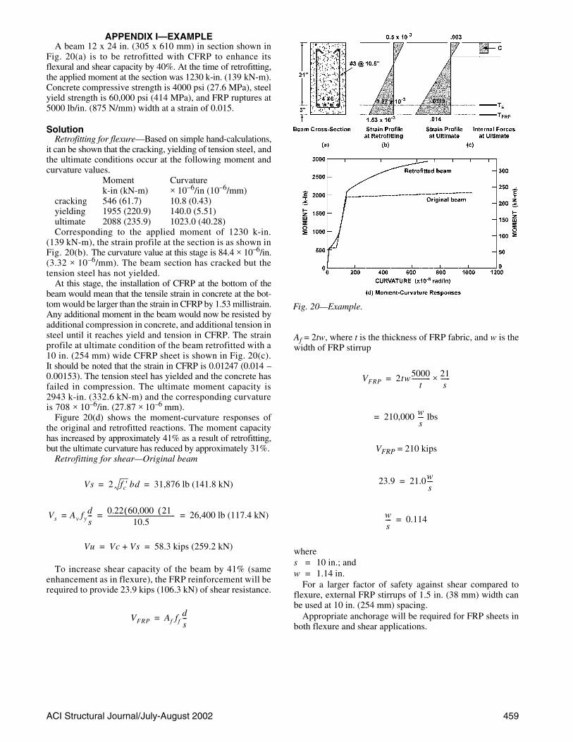
APPENDIX I—EXAMPLEA beam 12 x 24 in. (305 x 610 mm) in section shown in
Fig. 20(a) is to be retrofitted with CFRP to enhance itsflexural and shear capacity by 40%. At the time of retrofitting,the applied moment at the section was 1230 k-in. (139 kN-m).Concrete compressive strength is 4000 psi (27.6 MPa), steelyield strength is 60,000 psi (414 MPa), and FRP ruptures at5000 lb/in. (875 N/mm) width at a strain of 0.015.
SolutionRetrofitting for flexure—Based on simple hand-calculations,
it can be shown that the cracking, yielding of tension steel, andthe ultimate conditions occur at the following moment andcurvature values.
Moment Curvaturek-in (kN-m) × 10–6/in (10–6/mm)
cracking 546 (61.7) 10.8 (0.43)yielding 1955 (220.9) 140.0 (5.51)ultimate 2088 (235.9) 1023.0 (40.28)Corresponding to the applied moment of 1230 k-in.
(139 kN-m), the strain profile at the section is as shown inFig. 20(b). The curvature value at this stage is 84.4 × 10⁻⁶/in.(3.32 × 10–6/mm). The beam section has cracked but thetension steel has not yielded.
At this stage, the installation of CFRP at the bottom of thebeam would mean that the tensile strain in concrete at the bot-tom would be larger than the strain in CFRP by 1.53 millistrain.Any additional moment in the beam would now be resisted byadditional compression in concrete, and additional tension insteel until it reaches yield and tension in CFRP. The strainprofile at ultimate condition of the beam retrofitted with a10 in. (254 mm) wide CFRP sheet is shown in Fig. 20(c).It should be noted that the strain in CFRP is 0.01247 (0.014 –0.00153). The tension steel has yielded and the concrete hasfailed in compression. The ultimate moment capacity is2943 k-in. (332.6 kN-m) and the corresponding curvatureis 708 × 10–6/in. (27.87 × 10⁻⁶ mm).
Figure 20(d) shows the moment-curvature responses ofthe original and retrofitted reactions. The moment capacityhas increased by approximately 41% as a result of retrofitting,but the ultimate curvature has reduced by approximately 31%.
Retrofitting for shear—Original beam
To increase shear capacity of the beam by 41% (sameenhancement as in flexure), the FRP reinforcement will berequired to provide 23.9 kips (106.3 kN) of shear resistance.
Vs 2 fc′ bd 31,876 lb (141.8 kN)= =
Vs Av fyds--- 0.22 60,000( ) 21( )
10.5------------------------------------------- 26,400 lb (117.4 kN)= = =
Vu Vc Vs+ 58.3 kips (259.2 kN)= =
VFRP Af ffds---=
Af = 2tw, where t is the thickness of FRP fabric, and w is thewidth of FRP stirrup
VFRP = 210 kips
wheres = 10 in.; andw = 1.14 in.
For a larger factor of safety against shear compared toflexure, external FRP stirrups of 1.5 in. (38 mm) width canbe used at 10 in. (254 mm) spacing.
Appropriate anchorage will be required for FRP sheets inboth flexure and shear applications.
VFRP 2tw5000t
------------ 21s
------×=
210,000 ws---- lbs=
23.9 21.0ws----=
ws---- 0.114=
Fig. 20—Example.