aci structural journal technical papernilanjan/aci_struc_2009.pdf · aci 318-083 appendix d (which...
TRANSCRIPT

868 ACI Structural Journal/November-December 2009
ACI Structural Journal, V. 106, No. 6, November-December 2009.MS No. S-2008-306.R2 received September 17, 2008, and reviewed under Institute
publication policies. Copyright © 2009, American Concrete Institute. All rights reserved,including the making of copies unless permission is obtained from the copyright proprietors.Pertinent discussion including author’s closure, if any, will be published in the September-October 2010 ACI Structural Journal if the discussion is received by May 1, 2010.
ACI STRUCTURAL JOURNAL TECHNICAL PAPER
Section 12.6 provisions of ACI 318-08 detail the development ofheaded and mechanically anchored deformed bars for the first timein the Code series. Prior to this, Joint ACI-ASCE Committee 352published design recommendations for headed reinforcement usedin reinforced concrete beam-column joints (ACI 352R-02).However, both ACI 318-08 and 352R-02 are based on quite limitedexperimental research. Given this concern, these ACI standardsand recommendations were evaluated using an extensive databaseencompassing most available test data for reinforced concretebeam-column joints with headed bars subjected to reversed cyclicloading. The primary objectives of this study are to document theexperimental investigations in a uniform format; provide a detailedreview for the test data; and, finally, propose design guidelines tosupplement ACI 352R-02 and 318-08 on the subject of headed barsanchored in beam-column joints.
Keywords: beam-column joints; headed bars; reinforced concrete; seismic.
INTRODUCTIONHeaded deformed reinforcing bars (referred to as “headed
bars” hereafter) are becoming increasingly popular aslongitudinal and transverse reinforcement for relativelylarge reinforced concrete structures that are exposed toextreme loads such as earthquakes or blasts. The use ofheaded bars often provides an adequate solution to steelcongestion, particularly at beam-column joints, outriggerbeam-column connections, or pile-footing connections ofheavily reinforced buildings and infrastructures.
A combination of the bond between concrete and steel(along the length of the bar) and head bearing contributes tothe anchorage capacity of a headed bar, somewhat like thecombination of the bond and bearing of the hook that worksfor a conventional hooked bar. Previous research1,2 identifiedthat proportions of the bond and bearing that contribute tothe anchorage capacity are approximately equal for headedbars used in beam-column joints subjected to relatively smalldeformations. The bearing of the head, however, provides agreater portion of resistance as the bond deteriorates due tointensive cracking at the beam-joint (or column-joint)interface as well as inside the joint core.
New code provisions for headed bars have been added tothe 2008 edition of ACI 3183 (Sections 12.6.1 and 12.6.2),which detail the development of headed and mechanicallyanchored deformed bars in tension. These provisions includerequirements for development length, material properties,reinforcing bar size, and net bearing area of the head (Abrg),as well as clear concrete cover and bar spacing. Here, the netbearing area Abrg is defined as the gross head area Aheadminus the larger of the obstruction area Aobs or the bar area Ab(refer to Fig. 1 and also ACI 318-08,3 Sections 2.2 and 3.5.9).
The calculated development length ldt in tension for headedbars specified by ACI 318-083 was determined based solelyon the results of tests conducted at the University of Texas at
Austin, as reported by Kang.4 The ldt equation in ACI 318-083
results in the development lengths of approximately 30 and80% of those required for straight and hooked bars, respectively.Certain limitations (Section 12.6.1) are specified based on thelower bound of the data used for the establishment of ldt(Section R12.6). These include data from tests of headedbars in lap splices,5 single-headed bars embedded inbeams,6,7 and headed bars subjected to pullout,8 as reportedby Kang.4 These specimens5-8 are less prone to steel congestionproblems and have a much lower degree of concrete confinementthan typical beam-column joints have. Previous data frombeam-column joint subassembly tests1,2,9 have not beenincluded in this data set. As a result, some of the limitations setforth in Section 12.6.1 appear to be overly strict for beam-column joints, particularly with regard to clear bar spacing.
This can be a significant limitation, as the beam-columnjoint region mostly involves the use of headed bars that areneeded to reduce reinforcing congestion, and also becausetypical bar clear spacing in a beam or column ranges fromonly 1db to 3db (as per Sections 7.6 and 12.2.2 of ACI 318-083)versus the limit of 4db prescribed in Section 12.6.1(f).Currently, no provisions exist in Chapter 21 regardingheaded bars (versus hooked or straight bars) used in beam-column joints of structures exposed to low to high seismichazard. Therefore, for both seismic and nonseismic designs,the overly strict requirements of Section 12.6 must be
Title no. 106-S81
Seismic Design of Reinforced Concrete Beam-Column Joints with Headed Barsby Thomas H.-K. Kang, Myoungsu Shin, Nilanjan Mitra, and John F. Bonacci
Fig. 1—Defined notation for various dimensions (definitions:refer to Notation section).

869ACI Structural Journal/November-December 2009
followed. Given this concern and the need to supplementACI 318-083 on the subject of headed bars anchored inbeam-column joints, this study assembles a comprehensivedata set of experimental studies of beam-column joints withheaded bars and assesses the applicability and feasibility ofthe design criteria required in Section 12.6.1 of ACI 318-08.3
As an added objective, Joint ACI-ASCE Committee 352,Joints and Connections in Monolithic Concrete Structures,agreed to update its recommendations related to headed bars(Section 4.5.3 of ACI 352R-0210). As part of these efforts, atask group within this committee has compiled most availabletest data concerning headed bars terminating in reinforcedconcrete beam-column joint subassemblies. All of thesespecimens were subjected to considerable inelastic lateraldisplacement reversals; thus, the review focuses on caseswhere moderate-to-high seismic risk exists. Because a forcemechanism for knee-type joints is quite different from thatfor other types (for example, interior, exterior, and roof-interiorconnections), the discussion for a special case of knee joints isnot included in this paper (refer to the report by Kang11). Theprimary objectives of this study are to document all these testresults in a uniform format and conduct a detailed review ofthe data to support the updating of the limited ACI 352R-0210
recommendations as well as ACI 318-083 Code provisions.
RESEARCH SIGNIFICANCEACI 318-083 and other standards do offer practical provisions
for the design of beam-column joints with headed bars,although some detailing restrictions set forth in Section 12.6.1of ACI 318-083 (for example, maximum fc′ and minimum clearbar spacing) are not feasible for application to joint design.Relatively few details are given in ACI 352R-0210 due toa substantial lack of experimental data on beam-columnjoints involving headed bars, particularly those underinelastic deformation reversals. There are only a few availablereports on such seismic tests published in English.1,2,9,12,13
This research directly addresses the aforementioned concernsby assembling and reviewing most available international dataof beam-column joints subjected to reversed cyclic loading.
SUMMARY OF ACI STANDARDSAND RECOMMENDATIONS
Design approaches for headed bars or headed anchorsgiven in ACI standards and recommendations are brieflysummarized in this section. Current efforts of ACI andJoint ACI-ASCE committees on these subjects are alsointroduced.
In 2008, new provisions for headed bars were added in theACI 318. Sections 12.6.1 and 12.6.2 detail the developmentof headed bars and the limiting conditions for use of headedbars. ACI 318-083 also introduces new provisions (Section 3.5.9)for obstructions or interruptions of the bar deformations, whichshould not extend more than 2db from the bearing face of thehead. ASTM A970/A970M-07,14 “Standard Specificationfor Headed Steel Bars for Concrete Reinforcement,” shouldalso be satisfied by the requirements of Section 3.5.9.
While not directly applicable to headed deformed bars,ACI 318-083 Appendix D (which adopts recommendationsof ACI 349-0115 Appendix B) and ACI 355.1R-9116 provideguidelines for the design of plain headed bars and headedanchors, bolts, or studs (headed anchors, hereafter) in concrete.In ACI 318-083 Appendix D, the concrete capacity design(CCD) methodology is used to determine the anchoragecapacity of headed anchors installed in mass plain concrete. Inthe CCD method, no bond stress is assumed along the length ofa bar, and the concrete is assumed to be unconfined.
Design guidelines for headed bars in beam-column jointswere incorporated into the 2002 edition of the ACI 352R10
report on the basis of both monotonic8,9,17 (or repeated9) andreversed cyclic tests.1,9 This report recommends the developmentlength for headed bars along with some other specifics such asthe location of heads and the amount of head-restrainingreinforcement required to prevent prying action of headedbars placed near the concrete-free surface. ACI 352R-0210
defines two different development lengths of headed bars asfunctions of (fydb / ) for Type 1 and Type 2 beam-columnconnections. A Type 2 joint is defined to have sustainedstrength under deformation reversals into the inelastic range,whereas a Type 1 joint is defined as a joint designed with noconsideration of significant inelastic deformation. The criticalsection for Type 2 joints is defined to be located at the outeredge of joint transverse reinforcement, and at the joint-memberinterface for Type 1 joints (Fig. 1).
Furthermore, as the concrete bearing capacity is substantiallyhigher in the diagonal compressive strut, ACI 352R-0210
(Section 4.5.3.2 and Fig. 4.9) recommends that a head belocated within 2 in. (51 mm) from the back of the joint core(refer to Fig. 1). For details of the head, ACI 352R-0210
refers to ASTM A970/A970M-98,18 where the net bearingarea Abrg was recommended to be greater than 9Ab. Thecurrent version of ASTM A970/A970M14 (2007) no longerspecifies a minimum Abrg.
To provide the state-of-the-art information on headedreinforcement, ACI Committee 408, Development andSplicing of Deformed Bars, and ACI Committee 439, SteelReinforcement, are jointly preparing a new report on HeadedEnds for Anchorage and Development of Reinforcing Bars.In this report, a broad overview of mechanical anchorage andheaded bars is provided, including definitions, historicaldevelopment, and descriptions of various types of headedend devices, as well as previous research and applications.This report refers to ACI 352R-0210 for the use of headedbars in beam-column joints.
fc′
ACI member Thomas H.-K. Kang is an Assistant Professor of civil engineering at theUniversity of Oklahoma, Norman, OK. He is Secretary of Joint ACI-ASCECommittee 352, Joints and Connections in Monolithic Concrete Structures, and is amember of ACI Committee 369, Seismic Repair and Rehabilitation; Joint ACI-ASCECommittee 423, Prestressed Concrete; and the ACI Collegiate Concrete Council. Hereceived the ACI Wason Medal for Most Meritorious Paper in 2009. His researchinterests include seismic design and rehabilitation of concrete joints, connections, andsystems, and the behavior of headed bars and fibers in concrete.
ACI member Myoungsu Shin is a Project Engineer at Rosenwasser/GrossmanConsulting Engineers, New York, NY. He is Secretary of Joint ACI-ASCE Committee 421,Design of Reinforced Concrete Slabs, and is a member of ACI Committee 447, FiniteElement Analysis of Reinforced Concrete Structures, and Joint ACI-ASCE Committee 352,Joints and Connections in Monolithic Concrete Structures. His research interests includeearthquake-resistant design and analysis of reinforced concrete structures.
ACI member Nilanjan Mitra is a Lecturer of civil engineering at CaliforniaPolytechnic State University, San Luis Obispo, CA. He received his PhD fromthe University of Washington, Seattle, WA, and his MTech from the Indian Institute ofTechnology, Kharagpur, India. He is a member of Joint ACI-ASCE Committees 352,Joints and Connections in Monolithic Concrete Structures; and 447, Finite ElementAnalysis of Reinforced Concrete Structures. His research interests include probabilisticevaluations and numerical simulation of reinforced concrete structures.
John F. Bonacci, FACI, is Director of Structural Engineering Design at KarinsEngineering Group, Sarasota, FL. He is a member and former Chair of Joint ACI-ASCE Committee 352, Joints and Connections in Monolithic Concrete Structures, andis a member of ACI Committee 374, Performance-Based Seismic Design of ConcreteBuildings, and Joint ACI-ASCE Committee 445, Shear and Torsion. His researchinterests include performance-based earthquake-resistant design, life extension ofcorrosion-damaged structural concrete, mechanics of structural concrete elements,and modeling of progressive collapse of multistory buildings.

870 ACI Structural Journal/November-December 2009
SUMMARY OF EXPERIMENTAL RESEARCHIn this section, most prior seismic testing programs and
test results are summarized, outlining the range of variousfactors that impact on seismic joint performance.
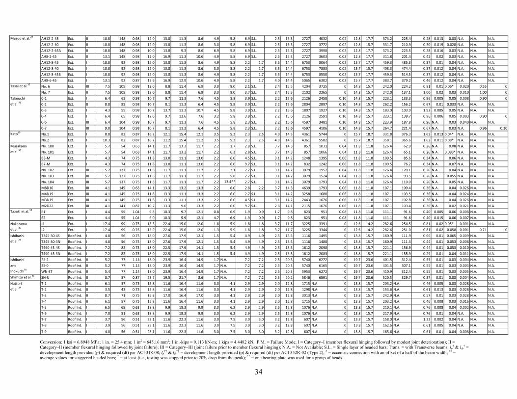
The dataset assembled in this work includes experimentaldata from a total of 93 reinforced concrete beam-columnconnection tests carried out by approximately 22 differentgroups of investigators around the world (Table A.1 in theAppendix*). The specimens were subjected to quasi-staticreversed cycling loading to simulate seismic forces. The testsinclude 69 interstory exterior connections, 17 (T-shaped) roof-interior connections, and seven knee connections (refer toFig. 2), all of which rely on member reinforcement terminatingin the joint region. Most of the beam-column joint specimenstested by Bashandy9 (except one) are not included becausethey do not have beams and were subjected to repeatedloading in the same drift direction (not reversed cyclic loading).
For the exterior connections, headed bars were employedfor top and bottom beam reinforcement while they were usedfor the column reinforcement in the roof-interior connections.Most of the subassemblies were planar without any transversebeam and slab; only a small number of the exterior connectionsincluded one or two transverse beam(s) framing perpendicularto the main beam into the column (refer to Table A.1 in theAppendix). Two of the exterior connections19 had one beamat each of the two principal directions of the rectangular-shaped column (that is, a corner column with two orthogonalbeams), and they were loaded in a combination of the twodirections. Of the exterior connection studies, one20
investigated the performance of headed bars used in a widebeam-column connection in which some of the headed barswere anchored in a transverse beam outside the joint. One13
was an eccentric exterior connection. Almost half of thespecimens had multiple layers of headed bars in the beam(s)or the column (Table A.1 in the Appendix).
The main test variables included the development lengthfor headed bars, clear cover to headed bars, type ofanchoring devices, and head size, as well as the compressivestrength of concrete and joint failure mode. The developmentlength provided for headed bars ranged widely from 6db to23.7db, when measured from the joint-member interface. Inmost specimens, the net head bearing area Abrg was 2.6 to 8 times
*The Appendix is available at www.concrete.org in PDF format as an addendum tothe published paper. It is also available in hard copy from ACI headquarters for a feeequal to the cost of reproduction plus handling at the time of the request.
the reinforcing bar area Ab. The tested compressive strength ofconcrete ranged approximately from 3.5 to 20 ksi (24 to138 MPa), and it was higher than 10 ksi (69 MPa) inapproximately 1/4 of the specimens. The tested clear barspacing cs in a layer varied from 1.2db to 7.6db, which wastypically not the design parameter varied among the specimensin each program.
The performance of headed bars used for beams and/orcolumns, terminated in the joint cores, was investigated forall types of joint failure modes including beam or columnhinging, joint shear failure, and bar bond-slip. Otherinvestigated design variables include the amount of beamand/or column bars, the amount of joint transverse reinforcement,the type of reinforcing steel, and the level of columncompression. The tested yield strength of steel ranged from43 to 148 ksi (297 to 1020 MPa), and was higher than 100 ksi(690 MPa) in approximately 1/3 of the specimens. Approxi-mately 1/2 of all specimens were tested with large-diameterheaded bars (No. 8 to 11; db = 25 to 36 mm). The preappliedcolumn compression varied from 0 to 12% of the columngross section area times the measured concrete compressivestrength ( fc,meas′ ). Details of the test parameters used in theinvestigated beam-column connection specimens aredocumented in Table A.1 in the Appendix.
In the following sections, the primary factors influencingthe action of headed bars in beam-column joints will beconsidered one at a time with respect to trends in the data withan aim toward improving existing recommendations for each.
DISCUSSION OF TEST DATA AND RELEVANCETO ACI 318-08 AND 352R-02
Failure modesAll the investigated joint subassemblies with headed bars
showed inelastic hysteretic behavior with some strength andstiffness degradations under reversed cyclic loading. Thetested specimens are categorized into three different groupsin terms of failure modes established by the writers asfollows: Category I: member flexural hinging followed bymodest joint deterioration; Category II: member flexuralhinging followed by joint failure; and Category III: jointfailure prior to member flexural hinging. The definition of“joint failure” includes cases with joint shear failure, significantbond slip, and a combination of both joint shear distress andbond slip. In this study, Category I specimens are consideredto exhibit “satisfactory seismic joint performance,” whilespecimens in the other two categories exhibit “unsatisfactoryseismic joint performance.” The performance indexesapplied by the authors for classification include: 1) the ratioof measured peak moment to nominal moment capacity(Mp /Mn); 2) drift ratio at the point of 20% drop from thepeak lateral load (δ0.8peak); 3) ratio of strain in the headedbar at the joint-member interface to yield strain; and 4) jointshear distortion during approximately 3.0% drift cycles,where Mn is estimated following ACI 318-083 procedures. Itis noted that the framework is used to organize data foranalysis and that the main findings are not overly sensitiveto the numerical benchmarks.
Joint failure was assumed to occur prior to flexuralhinging (Category III) if the ratio of (Mp/Mn) was less than1.0 and no bar yielding was monitored by strain gauges. Theheaded bars used for five specimens (No. 6 to 10; Kiyoharaet al.21) yielded at relatively large drift levels (approximately4%); however, Mp did not exceed Mn and the specimensexhibited a reduction in lateral stiffness. Thus, these specimens
Fig. 2—Schematic diagrams of investigated beam-columnjoint subassemblies with headed bars.
871ACI Structural Journal/November-December 2009
are included in Category III. The rest of the Category IIIspecimens (refer to Table A.1 in the Appendix) experi-enced a significant drop in strength after reaching the peakload values corresponding to Mp less than Mn. A variety ofdesign parameters appeared to cause the poor joint behavior,including relatively large joint shear demand (4 of 15; referto Columns (23) and (24) of Table A.1 in the Appendix)combined with a substantial lack of confinement by jointtransverse reinforcement (15 of 15; refer to Column (25) ofTable A.1 in the Appendix), or a lack of headed bar embedmentlength (8 of 15; refer to Columns (8) to (11) of Table A.1 in theAppendix). The specimens with the shorter embedmentlengths are discussed in detail later in this paper.
The drift ratio and the joint shear distortion were used todifferentiate between Category I and Category II. If the specimenexhibited less than a 20% reduction in strength until 3.5% drift,and did not exceed 1.2% of joint shear distortion (if reported)until 3.5% drift cycles, the joint was considered to haveexhibited satisfactory seismic performance and was classifiedas Category I. These benchmark values (or similar values) havebeen used or accepted by ACI Committee 37422 (ACI 374.1-05,Section 9.1.3) and by one of the authors2,12 or otherinvestigators.23,24 For the specimens in Category I, thedisplacement ductility μ was always larger than 2 (groupaverage equals 5.5), where μ is defined as (δ0.8peak/δy). Forthe specimens in Category II, joint failures occurred alsoafter flexural yielding, but with much less ductility (groupaverage equals 2.6).
Based on the slip measurements (if reported), bar slipswere limited to less than 0.04 in. (1 mm) at 2% drift ratio forthe specimens2,21,25-27 in Category I except three28 (0.08 to0.12 in. [2 to 3 mm]). Further, the performance of thespecimens2,12,13 evaluated based on the ACI 374.1-0522
criteria, including pinching indexes, was acceptable; thus,the large drift ratios recorded from these Category I specimenswere not due to excessive bar slips and associated stiffnessreduction. The contribution of bond slips to the drift ratiocould not be small, but it would not affect the overalleffectiveness of the head anchorage.
The joint failures (Category II) resulted mainly fromsubstantial joint shear distortion, along with moderate bonddeterioration of reinforcement within the joint. Even afterbond deterioration, head bearing resistance was maintainedwith a relatively small loss. Some degree of pinching (bondslips) is common for reinforced concrete beam-columnjoints that are part of moment frames when subjected tocyclic loading, and it is tolerable. The bar stress determinedfrom measured strain just in front of the head dropped byonly 0 to 30% (average Δσh/Δσh_max = 10%) of the peakvalue for specimens in all failure mode categories for whichbar strain data were reported (refer to Column (30) of Table A.1in the Appendix). This indicates that for these specimens,anchorage (that is, bearing) of the headed bar was notsignificantly deteriorated throughout the test.
Ten of the 27 Category II specimens appeared to beadversely affected by a lack of proper bond development (P1to P4,20 No. 5,21 AH8-2-45,29 2S-2, 2S-0 and WN-ST,30 andSN-U31). This is based on the reported observations20,21,29-31
and the data exhibiting an abrupt increase in bar slip,21 or asudden drop in lateral load with little residual strength.29
Also, modest joint shear distortion30,31 (refer to Column (28)of Table A.1 in the Appendix) or sufficient jointconfinement20 (refer to Column (25) of Table A.1 in theAppendix) indirectly indicates that bond deterioration was
rather a major cause of poor performance of these connections.These specimens are discussed in detail in each of thefollowing subsections.
Development length for headed barsin beam-column joints under cyclic loads
Development length ldt equations for headed bars in bothACI 318-083 and 352R-0210 are functions of (fy db/ )(refer to ACI 318-08,3 Section 12.6.2 and ACI 352R-02,10
Section 4.5.3). The difference is only in the constants.Certain limitations such as clear concrete cover, bar spacing,and head size should be applied to ensure adequate developmentand anchorage of a headed bar (refer to Sections 12.6.1 andR12.6). From all of the tests for which the relevant data werereported, it was observed by the authors that the portion ofbond contribution to the anchorage capacity of headed barswas large at small drift levels. As the bond deteriorated withincreasing drifts, however, the head bearing played a significantrole in anchorage during the inelastic stage (after approximately2.5 to 4% drift). This implies that both bond along thedevelopment length and head bearing ultimately contributed tosurviving substantial lateral drifts and achieving satisfactoryjoint behavior, but by different extents at various drift levels.In light of this behavior, it appears reasonable either that aterm associated with head bearing be included in thedevelopment length equation as a parameter or thatcertain requirements relating to head bearing are specified toachieve the desired connection behavior in the inelasticrange of the deformation.
Figure 3 illustrates the provided development length forheaded bars used in the investigated Category I specimensand Category II and III specimens that were affected byimproper bond development, compared with the valuesrequired by ACI 318-083 and 352R-02.10 The ACI 318-083
equation resulted in conservative estimations for the Category Ispecimens, which exhibited satisfactory seismic performance.On the other hand, most of the Category I (37 of 44) specimensare located on the left side of the ACI 352R line, indicatingthat the ACI 352R equation corresponds quite well with thedata. These findings apply to both Category I specimens witha single layer of headed bars and those with multiple layers.
Figure 3 also illustrates that most Category II and IIIspecimens that were affected by improper bond developmentdid not satisfy either ACI 318-08 provisions or 352R-02recommendations for development length, indicating that adesigner has a proper tool to rule out these bond-slip failures.For the specimens that exhibited premature failures (Category IIand III) despite complying with the ACI 352R-0210 developmentrequirement (refer to Columns (10) and (11) of Table A.1 inthe Appendix),21,25,28,29,32-34 the primary failure mode wasjoint shear failure (not shown in Fig. 3 for clarity). This isbased on the reported observations and the data in Table A.1in the Appendix. In conclusion, an examination of theexperimental data indicates that the ACI 318-083 equationgives somewhat conservative ldt requirements for headedbars in joints, and that the current ACI 352R10 recommendationfor development length ldt appears reasonable for both singleand multiple layers of headed bars anchored in the Type 2beam-column joint. Thus, an amendment of the ACI 352defined ldt for the Type 2 joint is not recommended untilsufficiently detailed investigations are carried out.
fc′

872 ACI Structural Journal/November-December 2009
Headed bar clear spacingACI 318-08,3 Section 12.6.1(f), specifies that the
minimum clear spacing between headed bars should be 4db.This specified minimum clear spacing cs is significantlylarger than the value required for beam reinforcement (= 1dbper Section 7.6.1) or column reinforcement (= 1.5db perSection 7.6.3) terminating without heads, and even largerthan those having been used in practice for both hooked andheaded bars (1db to 3db). According to Section R12.6 ofACI 318-083 and the report by Kang,4 the minimum limitof 4db was determined based on the lower bound valuesobtained from 10 lap splice tests5 and two pullout tests.8
Given that the minimum spacing cs of 4db has been developedbased on limited data (which have not involved beam-columnjoints), it is suggested that the requirement be reviewed throughfurther research on additional experimental investigations.
The ACI 352R-0210 recommendations do not provideguidelines for clear spacing between headed bars in a layer;therefore, the clear bar spacing specified for conventionalreinforcing bars would also be used for headed bars as perACI 318-08, Sections 7.6.1 and 12.2.2, where the bondcapacity is known to be affected by the clear bar spacing,when less than 2db. For the clear spacing not less than 2db,bond may not be a serious issue for all types of bars (hooked,headed, or straight). The clear bar spacing between headed
bars may affect the concrete breakout capacity “near thehead.” Figure 4 (‘x’ marks) illustrates that there is noapparent relationship between the clear bar spacing andseismic bond performance.
For the 44 specimens falling under Category I, the clearbar spacing was less than 4db in 33 specimens and close toor even less than 2db in nine specimens, with the average andthe lowest spacing being 2.8db and 1.2db, respectively (referto Fig. 4). For the Category I specimen tests, there were noapparent anchorage splitting cracks, side-face blowoutfailure, or concrete breakout failure; and there were no dataproviding evidence that bearing or pullout failure occurred.Moreover, these kinds of failures were not reported from thetests of Category II and Category III specimens with clearbar spacing less than 4db. Further, it is shown that the smallclear bar spacing did not adversely affect the drift ratiomeasured at a drop to 80% of the peak lateral load (refer toColumns (14) and (27) of Table A.1 in the Appendix), whichis considered as one of the seismic performance indicators inthis study. Therefore, it is concluded that there was no influenceof the clear bar spacing, if not less than 2db, on the lateral forceresistance of the tested beam-column connections.
Based on these observations of the available experimentaldatabase, a recommended limit of 2db is proposed to be usedfor the design of beam-column joints instead of the currentlimit of 4db. The Category I data26,35,36 that met the ACI 318requirements for ldt, (Abrg/Ab), and clear cover to the bar(csb) can be considered to lower the minimum clear spacingcs to 2db even in general (ACI 318-08, Section12.6.1). Theproposal was made during public discussion period onACI 318-08.3 ACI Committee 318 responded that theclear bar spacing issue would need to be addressed as newbusiness in the next code cycle and the committee encouragedfuture research. For headed bars with (Abrg/Ab) greater than 8(circular head) or 10.5 (square head) and without anyobstructions, the clear bar spacing of 2db causes overlappingof the heads. In this case, it is recommended to stagger theheads (Section R12.6) as required to fit all bars within availablewidth and maintaining a clear distance between heads.
Limitation for concrete and reinforcing barsAccording to Sections 12.6.1 and 12.6.2 of ACI 318-08,3
the specified yield strength of a headed bar ( fy) and the valueof fc′ used to calculate ldt should be limited to 60 and 6 ksi(420 and 41 MPa), respectively. On the other hand, theACI 352R-0210 recommendations are valid for fy up to 78 ksi(540 MPa) per ASTM A970/A970M,14,18 and for fc′ up to 15 ksi(100 MPa). For the Category I specimens, the measured yieldstrength of steel varied from 51 to 103 ksi (352 to 710 MPa)(Fig. 5). In particular, 16 of these specimens had high-strength steel with fy higher than 78 ksi (420 MPa). Forconcrete, the measured compressive strength on the testingday ranged from 3.7 to 18.8 ksi (25.4 to 130 MPa). These testresults of satisfactory joint behavior (Category I) support theACI 352R-0210 recommendations that the use of high-strength steel having fy up to 78 ksi (420 MPa) and high-strength concrete having fc′ up to 15 ksi (100 MPa) bepermitted for both Type 1 and 2 joints with headed bars.
Only one31 of 44 specimens with fc,meas′ ≥ 6 ksi (41.4 MPa)experienced a substantial bond slip, although they met theACI 318 requirement for ldt (Table A.1 in the Appendix andFig. 3(a)), possibly due in part to the lack of confinement (referto Column (22) of Table A.1 in the Appendix). In general, theuse of fc′ values of 6 to 15 ksi (41.4 to 103 MPa) for ldt
Fig. 3—Comparison between provided and requireddevelopment lengths.
Fig. 4—Bar clear spacing in a layer versus bar diameter.

ACI Structural Journal/November-December 2009 873
appears warranted. It is additionally noted that the performancewas unsatisfactory for all beam-column joints with very high-strength steel (fy > 140 ksi [815 MPa]), likely due to shorterdevelopment lengths than those required by ACI 318-08 (or352R-02) (Fig. 5 and Table A.1 in the Appendix). The jointdesign may not be feasible (very large dimension) if thedevelopment length requirement would be satisfied. Futureresearch efforts will be needed to study the use of high-strength materials in beam-column joints.
In both ACI 318-083 and 352R-02,10 the maximum allowablesize of the headed bar is a No. 11 (db = 1.41 in. [36 mm]),and only normalweight concrete is permitted when headedbars are employed as reinforcement (Section 12.6.1(c)). Onthe contrary, ASTM A970/A970M14,18 allows the use ofNo. 14 (db = 1.69 in. [43 mm]) and No. 18 (db = 2.26 in.[57 mm]) headed bars, which are common for bridges andnuclear plants. From surveying the considered test database,the maximum headed bar diameter used for the Category Ispecimens was 1.41 in. (36 mm) (Fig. 4), which remainedwithin that specified by ACI 318-083 and 352R-02.10 Therewere no available data for lightweight concrete, that is,normalweight concrete was used for all specimens. Due tothis lack of data, no recommendations to allow or limit useof a larger bar size and lightweight concrete are possiblefrom this study.
Head sizeAs discussed previously, both the development length and
head size determine the anchorage capacity of a headed bar.After considerable bond deterioration (at approximately 2.5to 4% drift), anchorage relies in large part on the headbearing acting against the concrete. Therefore, the head sizeshould be large enough to ensure that no pullout (due to localcrushing) eventually occurs at the face of the head during thisstage. The larger head size, however, does not necessarilywarrant a shorter development length needed to ensureadequate bond behavior at low-to-moderate drift levels (upto 2.5%) (refer to ‘x’ marks in Fig. 6).
ACI 352R-0210 recommends Abrg be at least 9Ab by referringto the 1998 version of ASTM A970/A970M,18 whereas ACI318-083 requires Abrg be at least 4Ab. Two different types ofheads were used in the investigated tests: 1) heads without asleeve connection, and 2) heads with a sleeve connection. Inthe first case, Abrg is calculated as the difference between Aheadand Ab, while in the second case, Abrg may be taken as asmaller value equal to Ahead minus Aobs (refer to Fig. 1 fordefinitions). In this paper, as the information on Aobs is notavailable for a vast majority of the tests in the literature, Abrgis approximately taken as Ahead minus Ab, conservatively(leading to slight overestimation of the head size associatedwith a given performance). The value of Aobs is often difficultto obtain, as the obstruction is not always circular in crosssection and this information may not be provided by the manu-facturer; however, in a design case, ignoring the obstruction isnot recommended by ACI 318-083 (Section R3.5.9).
The specimens falling in Category I reached more than3.5% drifts with modest strength degradation (less than 20%of the maximum strength). Eight of the 44 Category Ispecimens possessed Abrg equal to or smaller than 4Ab, withthe lowest value of 1.7Ab (Fig. 6). Three1,2 of these eightspecimens had a combination of a small Abrg (not greaterthan 4Ab) and a small development length (lp ≈ ldt), where ldtis the ACI 352R recommended development length of aheaded bar in a Type 2 joint. Also, two12,36 of the eight
specimens had Abrg values of 1.7Ab and 2.6Ab with relativelysmall lp values (refer to Fig. 6). For these five specimens, nosigns of concrete breakout or pullout were identified (asreported in the literature).
Strain measurements also indicated that the reduction inbearing resistance was modest (average Δσh/Δσh_max = 7%)for Category I specimens whose data are available (refer toColumn (30) of Table A.1 in the Appendix). Further, headbearing drop began to occur beyond 3% drift ratio except one(No. 326 at 2% drift). For the Category II and Category IIIspecimens with shorter development lengths than required,however, bond anchorage performance was not satisfactorydespite the large head size (Abrg/Ab ≥ 5.7) (Fig. 6, andColumn (30) of Table A.1 in the Appendix). Based on theresults in this subsection, a minimum head size of (Abrg/Ab = 4)is feasible for headed bars terminating in beam-columnjoints, provided that the development length of the barcomplies with ACI 352R-02.10 Perhaps, a size of (Abrg/Ab = 3)will even be allowed for the seismic design of beam-columnjoints (pending the outcome of the Joint ACI-ASCE Committee352’s deliberations). It is noted that ACI 318-08, Chapter 12does not consider seismic loading; thus, the findings are ofvalue in updating ACI 352R-02 and ACI 318-08, Chapter 21.
Fig. 5—Tested concrete and steel properties.
Fig. 6—Head size versus provided development length.

874 ACI Structural Journal/November-December 2009
In U.S. design practice, beam-column joint dimensions aretypically determined based on joint shear requirementsrather than those for bar development length (unless high-strength steel is used). In addition, the headed bar is recom-mended to extend to the far face of the joint core (SectionR12.6 of ACI 318-083 or Section 4.5.3.3 of ACI 352R-0210;refer to Fig. 1). Thus, embedment lengths in the joints aretypically approximately 1.5 to 2ldt , which leads to lessbearing demand placed on the head (then, head size may notbe a significant concern for beam-column joints).
Side clear concrete coverThe minimum clear cover required by Section 7.7 of
ACI 318-083 is primarily intended to protect reinforcementagainst extreme weather and/or fire. Following Sections7.7.1(c) and R7.7, the clear cover to the outermost part of thehead (cch) should not be less than 1.5 in. (38 mm) (refer toFig. 1). At the same time, for the purpose of preventing side-face blowout, ACI 318-08,3 Section 12.6.1(e), sets a lowerlimit for the clear cover to the headed bar (ccb) as 2db (referto Table 1). Both requirements of Sections 12.6.1(e) and7.7.1(c) are, in general, not difficult to meet for headed barsanchored within a beam-column joint, if adequate clearcover is also provided for the joint transverse reinforcementbased on Section 7.7.
ACI 352R-0210 does not provide explicit recommendationsfor minimum clear cover to the head. Rather, ACI 352R-0210
specifies the minimum amount of restraining reinforcementengaging the headed bar just before the head which is needed
to produce the strength of 0.25As fy for a Type 1 joint or0.5As fy for a Type 2 joint, where As is the headed bar areanear the free surface. This head-restraining reinforcementshould be provided for all headed bars adjacent to a free faceof the joint, such as beam bars in a joint having any freevertical face (for example, interstory corner joint), and topbeam bars in an exterior joint with a discontinuous column.When ccb is greater than 3db, ACI 352R-0210 allows reducingthe amount (As,rst) of the head-restraining reinforcement andrecommends that the reduced amount be estimated byconsidering the resisting force Rlb to lateral burstingaccording to ACI 349-9737 as
Rlb = 4 (ca1)2π = As,rst fy; (1)
Rlb = 0.33 (ca1)2π = As,rst fy;
where ca1 is equal to (ccb + 0.5db) or (cch + 0.5dhead) (referto Fig. 1). Note that the resisting force Rlb equation is nolonger available in the 2001 version of ACI 349.15 The head-restraining reinforcement, however, is not required in anycase by ACI 318-08.3 This is based on the results of thetests5-7 showing that reinforcement placed transverse to theheaded bar did not increase the anchorage strength.
Figure 7 depicts the tested range of side clear cover to thehead (cch) for the Category I specimens, along with comparisonsto Sections 7.7.1 and 12.6.1(e), and Eq. (D-17) of ACI 318-08.3
The side clear cover cch required to prevent side-faceblowout can be estimated by setting Eq. (D-17) of ACI 318-083
equal to the maximum bar force of 1.25As fy and solving forca1 (= ccb + 0.5db; refer to Fig. 1) as
Nsb = 160ca1 λ = 1.25As fy; (2)
Nsb = 13.33ca1 λ = 1.25As fy
where Nsb is the nominal side-face blowout strength ofheaded anchors, λ is assigned as 1 for normalweightconcrete, and Abrg is set equal to a lower-bound value of 4Abfor Eq. (2). The previous equation was developed for caseswhere the concrete is unconfined; thus, it is conservative toapply it to well-confined beam-column joints.
In five of the Category I specimens, cch was smaller thanthe values given by Section12.6.1(e), as shown in Fig. 7. Forall the interstory exterior joints including those five, nohorizontal head-restraining reinforcement was provided, asit was not a common practice. Side-face blowout or spallingof the side clear cover, however, was not observed in any ofthe Category I joints. The absence of side-face blowout failureswas also supported by strain data measured in joint hoops.1,34
The hoop strains were below 2500 μs until the drift exceeded3%, indicating that the satisfactory behavior was attributedin part to good lateral confinement of the joint core near thehead. The head was located entirely (for exterior joints) orpartly (for roof-interior joints) within the core. Furthermore,the joints classified as Category II or Category III did notexperience side-face blowout, nor did the joints with closelyspaced beam bars adjacent to free vertical faces of thejoint.2,28,29,35,38,39 Only three roof-interior joints30 inCategory III experienced moderate spalling of the concretecover on the free face of the column, likely due to significant
fc′ (psi)
fc′ (MPa)
Abrg fc′ (psi)
Abrg fc′ (MPa)
Table 1—Comparison between Section 12.6.1(e) and 7.7.1(c) of ACI 318-08
Bar sizedb, in. (mm)
Ab, in.2
(mm2)ccb, in. (mm)
cch†, in.
(mm)cch
††, in. (mm)
No. 6 0.75 (19) 0.44 (284) 1.50 (38) 1.04 (26) 1.50 (38)
No. 7 0.88 (22) 0.60 (387) 1.75 (44) 1.22 (31) 1.50 (38)
No. 8 1.00 (25) 0.79 (510) 2.00 (51) 1.38 (35) 1.50 (38)
No. 9 1.13 (29) 1.00 (645) 2.26 (57) 1.56 (40) 1.50 (38)
No. 10 1.27 (32) 1.27 (819) 2.54 (65) 1.76 (45) 1.50 (38)
Note: ccb is clear cover to the headed bar per Section 12.6.1(e); cch† is clear cover to
outermost part of the head per Section 12.6.1(e), for circular heads with (Abrg/Ab) = 4;
cch†† is clear cover to the outermost part of the head per Section 7.7.1(c).
Fig. 7—Side clear cover to the head for Category I specimens.

ACI Structural Journal/November-December 2009 875
interfacial debonding; however, there was no apparent side-face blowout failure.
Based on the results showing that side-face blowout is nota concern, the requirement of Section 12.6.1(e) of ACI 318-083
can also be applied for headed bars terminating in beam-column joints. Furthermore, a design recommendation isproposed such that horizontal head-restraining reinforcementis not required for headed beam bars adjacent to a freevertical face of an interstory joint, provided that the requirementof Section 12.6.1(e) of ACI 318-083 is met, and that thelateral confinement is supplied by closed joint hoops and byat least one beam member covering at least three quarters ofthe column width.
Multiple layers of headed barsOf the 93 beam-column joint subassemblies, a total of 22
interstory exterior specimens had two layers of top beambars, with clear spacing between the layers ranging from0.9db to 2.5db (Fig. 8). A total of 17 roof-level interior specimenshad multiple column headed bars adjacent to free vertical facesof the columns, with clear bar spacing ranging between 2.9dband 7.6db (Fig. 8). As discussed, none of these specimensexhibited side-face blowout. The clear spacing cl betweenthe layers was smaller than 2db for nine specimens (JM-22;AH12-8-series and AH8-6-4529; No. 1 and No. 235; E1and E238; J1 and J239) in Category I, and even smaller than1db for two specimens (E1 and E238). These specimensexhibited little drop in lateral loads from the peak value until3% drift ratios (refer to Fig. 8). For the specimens inCategory I with the strain gauge data available,2,25,39 it wasreported that head bearing resistance was maintained withminimal loss (average Δσh/σh_max = 10%; refer toColumn (30) of Table A.1 in the Appendix). On the otherhand, the specimens of Category II and III with multiplelayers of headed bars failed in joint shear (non-bond failure),if they had an embedment length greater than required byACI 318-08 and 352R-02.
Maximum head bearing stress (pbrg = Abnfy,meas /Abrg) wasestimated to be 4.1fc′ for the 11 Category I specimens forwhich bar strain data were monitored (Fig. 9), where Ab isthe cross-sectional area of a headed bar, fy,meas is themeasured yield stress of steel, and n is the ratio (maximumof 1.0) of the maximum strain measured in the bar just beforethe head to the yield strain εy of the headed bar. The estimatedbearing stresses were quite higher than that permitted (1.7fc′ )by ACI 318-08, Section 10.14.1, but close to those (2fc′ to5fc′ ) monitored during CCT node tests6 with (Abrg/Ab)ranging from 3 to 5. The higher concrete bearing stress infront of the closely spaced heads can be attributed to well-confined concrete (refer to Column (25) of Table A.1 in theAppendix) as well as compressive strut action. Based on theresults from nine Category I specimens with cl less than 2dband a higher bearing stress capacity of the joint core than theunconfined concrete, multiple layers of headed bars aresuggested to be allowed with a minimum clear spacing of2db between the layers.
SUMMARY AND RECOMMENDATIONSA detailed review of previous research on the use of
headed bars in reinforced concrete beam-column jointssubjected to quasi-static reversed cyclic loading is presentedin this paper. The investigated database comprises mostavailable experimental tests on this subject around the world,including those conducted in the U.S., Korea, Japan, and
Taiwan (Table A.1 in the Appendix). The test database wasassessed to evaluate the new ACI 318-08, Section 12.6,requirements for applications in beam-column joints and tosupplement the current ACI 352R-02 report. The recommenda-tions and conclusions that can be drawn based on this reviewinclude the following:
1. The development length ldt for headed bars in beam-column joints that ACI 352R-02 recommends corresponds tothe experimental data, while the ldt specified by ACI 318-08is relatively much more conservative for headed bars inbeam-column joints. Therefore, the equation of ACI 352R-02can be included in Section 21.7.5 of ACI 318-08.
2. Test results indicate that bond along the length of theheaded bar and bearing of the head both contributed to theanchorage capacity, but by different extents at various driftlevels. Thus, either minimum head size should be specified toensure the desired nonlinear joint behavior, or a term associatedwith head bearing may be considered in the developmentlength equation for further detailed investigation.
3. Based on the review of the previous data, the net bearingarea of a head is suggested to be at least three times the bararea for the design of beam-column joints. The data of beam-column joints subject to cyclic loading provide a means toupdate both ACI 352R-02 and ACI 318-08, Chapter 21.
4. For the beam-column joint design, the minimum clearspacing between headed bars can be reduced to 2db from
Fig. 8—Beam-column joints with multiple layers of headed bars.
Fig. 9—Head bearing stress versus net bearing area for allcategories.

876 ACI Structural Journal/November-December 2009
4db, which is required by ACI 318-08. This is based on theobservation of no influence of headed bar clear spacing (cs)on the lateral resistance of the beam-column joint, with csranging from 1.2db to 7.6db. The data from beam-columnjoints that performed satisfactorily and met the ACI 318requirements for ldt, (Abrg/Ab) and cs can be considered tolower the minimum clear spacing cs to 2db even in general(ACI 318-08, Section 12.6.1). Also, multiple layers ofheaded bars can be used for beam-column joints with aminimum clear spacing of 2db between the layers.
5. The test results are consistent with the ACI 352R-02limitations on fc′ (up to 15,000 psi [100 MPa]) and fy (up to78 ksi [540 MPa]). Based on the review of the results, theACI 318 limits of fy (≤ 60 ksi [410 MPa]) and the valueof fc′ (≤ 6000 psi [41 MPa]) used to calculate ldt couldalso be expanded.
6. The ACI 318-08 requirements of the minimum sideclear covers to the head (cch = 1.5 in. [38 mm]) and to the bar(ccb = 2db) can be applied to headed bars used in beam-column joints. There were no side-face blowout failuresobserved in any groups of the investigated specimens with aminimum ccb of 1.5db.
7. The horizontal head-restraining reinforcement is notnecessary for headed beam bars adjacent to a free verticalface of an interstory joint, provided that the aforementionedclear cover requirements are met, and that the lateralconfinement is supplied by closed hoops within the joint andby at least one beam member covering at least 3/4 of thecolumn width.
ACKNOWLEDGMENTSThe affiliations of the authors should be acknowledged for their continued
support. Also, financial support from the the Oklahoma Transportation Center(OTCREOS9.1-27) is acknowledged. The authors would like to thankmembers of Joint ACI-ASCE Committee 352, Joints and Connections inMonolithic Concrete Structures, for their constructive comments andsuggestions regarding the content of this paper. The authors also wouldlike to thank S.-G. Hong (and his research team at Seoul National University),M. Murakami, and A. Tasai for helpful discussions and providing numerousresearch papers.
NOTATIONAb = bar areaAbrg = net bearing area of headAg = gross cross-sectional area of columnAhead = gross area of headAobs = cross-sectional area of obstructionAsh = area of joint transverse reinforcement in principal direction
within hoop spacing shAs,rst = amount of head-restraining reinforcementbj = effective joint width (ACI 352R-02)ca1 = distance from center of headed bar to edge of concreteccb = clear cover to barcch = clear cover to outermost part of headcl = clear layer spacing for multiple layers of headed barscs = clear bar spacing in a layerd = effective member depthdb = bar diameterdbh = distance measured from far end of joint core to back of headdhead = head diameterfc′ = specified concrete compressive strengthfc,meas′ = measured concrete compressive strength fy = specified yield stress of headed barsfy,meas = measured yield stress of headed barsh = joint depth (refer to Fig. R21.7.4 of ACI 318-08)h′′ = joint core widthldt = development length required for headed barlp = development length providedMn = nominal moment capacity calculated using specified tension
force and assumed internal level arm of 0.9dMp = measured peak moment of member
Nsb = nominal side-face blowout strengthn = ratio of maximum strain measured in bar just before head to εyP = applied column axial forcepbrg = estimated maximum head bearing stressRlb = resisting force to lateral burstingsh = joint hoop spacingVn = nominal joint shear capacity calculated based on ACI 352R-02Vp = maximum joint shear demand applied during testingΔσh = drop in bar stress from Δσh_max monitored during testingδ0.8peak= drift ratio at drop to 80% from peak lateral loadδy = drift ratio at first bar yielding (measured)εy = yield strainγj = maximum joint shear distortion during approximately 3.5%
drift cyclesρh = Ash/shh′′ρh
ACI,2= minimum value recommended by ACI 352R-02 for a Type 2 jointσh_max = maximum bar stress measured just before head
REFERENCES1. Wallace, J. W.; McConnell, S. W.; Gupta, P.; and Cote, P. A., “Use of
Headed Reinforcement in Beam-Column Joints Subjected to EarthquakeLoads,” ACI Structural Journal, V. 95, No. 5, Sept.-Oct. 1998, pp. 590-606.
2. Chun, S. C.; Lee, S. H.; Kang, T. H.-K.; Oh, B.; and Wallace, J. W.,“Mechanical Anchorage in Exterior Beam-Column Joints Subjected to CyclicLoading,” ACI Structural Journal, V. 104, No. 1, Jan.-Feb. 2007, pp. 102-113.
3. ACI Committee 318, “Building Code Requirements for StructuralConcrete (ACI 318-08) and Commentary,” American Concrete Institute,Farmington Hills, MI, 2008, 473 pp.
4. Kang, T. H.-K., “Recommendations for Design of RC Beam-ColumnConnections with Headed Bars Subjected to Cyclic Loading,” Proceedingsof the 14WCEE, Beijing, China, Oct. 2008, 8 pp. (Paper No. 08-01-0017).
5. Thompson, M. K.; Jirsa, J. O.; and Breen, J. E., “Behavior andCapacity of Headed Reinforcement,” ACI Structural Journal, V. 103, No. 4,July-Aug. 2006, pp. 522-530.
6. Thompson, M. K.; Ziehl, M. J.; Jirsa, J. O.; and Breen, J. E., “CCTNodes Anchored by Headed Bars—Part 1: Behavior of Nodes,” ACI StructuralJournal, V. 102, No. 6, Nov.-Dec. 2005, pp. 808-815.
7. Thompson, M. K.; Jirsa, J. O.; and Breen, J. E., “CCT NodesAnchored by Headed Bars—Part 2: Capacity of Nodes,” ACI StructuralJournal, V. 103, No. 1, Jan.-Feb. 2006, pp. 65-73.
8. DeVries, R. A.; Jirsa, J. O.; and Bashandy, T., “Anchorage Capacity inConcrete of Headed Reinforcement with Shallow Embedments,” ACIStructural Journal, V. 96, No. 5, Sept.-Oct. 1999, pp. 728-737.
9. Bashandy, T. R., “Application of Headed Bars in Concrete Members,”PhD dissertation, the University of Texas at Austin, Austin, TX, Dec. 1996,303 pp.
10. Joint ACI-ASCE Committee 352, “Recommendations for Design ofBeam-Column Connections in Monolithic Reinforced Concrete Structures (ACI352R-02),” American Concrete Institute, Farmington Hills, MI, 2002, 37 pp.
11. Kang, T. H.-K., “A Review of ACI Standards and Seismic Tests ofBeam-Column Joints with Headed Reinforcement,” Proceedings ofASEM’08, Jeju, Korea, May 2008, pp. 2299-2314.
12. Kang, T. H.-K.; Ha, S.-S.; and Choi, D.-U., “Seismic Assessment ofBeam-to-Column Interactions Utilizing Headed Bars,” Proceedings of the14WCEE, Beijing, China, Oct. 2008, 8 pp. (Paper No. 05-03-0047).
13. Lee, H.-J., and Yu, S.-Y., “Cyclic Response of Exterior Beam-Column Joints with Different Anchorage Methods,” ACI StructuralJournal, V. 106, No. 3, May-June 2009, pp. 329-339.
14. ASTM A970/A970M-07a, “Standard Specification for HeadedSteel Bars for Concrete Reinforcement,” ASTM International, WestConshohocken, PA, 2007, 6 pp.
15. ACI Committee 349, “Code Requirements for Nuclear SafetyRelated Concrete Structures (ACI 349-01) and Commentary (349R-01),”American Concrete Institute, Farmington Hills, MI, 2001, 134 pp.
16. ACI Committee 355, “Report on Anchorage to Concrete (ACI355.1R-91),” American Concrete Institute, Farmington Hills, MI, 1991, 71 pp.
17. Wright, J. L., and McCabe, S. L., “The Development Length andAnchorage Behavior of Headed Reinforcing Bars,” SM Report No. 44,Structural Engineering and Engineering Materials, University of KansasCenter for Research, Lawrence, KS, Sept. 1997, 147 pp.
18. ASTM A970/A970M-98, “Standard Specification for Welded orForged Headed Bars for Concrete Reinforcement,” ASTM International,West Conshohocken, PA, 1998, 7 pp.
19. Matsushima, M.; Kuramoto, H.; Maeda, M.; Shindo, K.; and Ozone, S.,“Test on Corner Beam-Column Joint under Tri-Axial Loadings,” Proceedingsof the Architectural Institute of Japan, Sept. 2000, pp. 861-863. (in Japanese)
20. Ishida, Y.; Fujiwara, A.; Adachi, T.; Matsui, T.; and Kuramoto, H.,“Structural Performance of Exterior Beam-Column Joint with Wide Width
877ACI Structural Journal/November-December 2009
Beam Using Headed Bars,” Proceedings of the Architectural Institute ofJapan, Aug. 2007, pp. 657-660. (in Japanese)
21. Kiyohara, T.; Hasegawa, Y.; Fujimoto, T.; Akane, J.; Amemiya, M.;Tasai, A.; and Adachi, T., “Seismic Performance of High Strength RCExterior Beam Column Joint with Beam Main Bars AnchoredMechanically,” Proceedings of the Architectural Institute of Japan,Sept. 2005, pp. 33-42. (in Japanese)
22. ACI Committee 374, “Acceptance Criteria for Moment FramesBased on Structural Testing and Commentary (ACI 374.1-05),” AmericanConcrete Institute, Farmington Hills, MI, 2005, 9 pp.
23. Naito, C. J.; Moehle, J. P.; and Mosalam, K. M., “Evaluation ofBridge Beam-Column Joints under Simulated Seismic Loading,” ACIStructural Journal, V. 99, No. 1, Jan.-Feb. 2002, pp. 62-71.
24. Canbolat, C. J., and Wight, J. K., “Experimental Investigation onSeismic Behavior of Eccentric Reinforced Concrete Beam-Column-SlabConnections,” ACI Structural Journal, V. 105, No. 2, Mar.-Apr. 2008,pp. 154-162.
25. Kiyohara, T.; Tasai, A.; Watanabe, K.; Hasegawa, Y.; and Fujimoto, T.,“Seismic Capacity of High Strength RC Exterior Beam Column Joint withBeam Main Bars Anchored Mechanically,” Proceedings of Architectural Instituteof Japan, Aug. 2004, pp. 27-34. (in Japanese)
26. Yoshida, J.; Ishibashi, K.; and Nakamura, K., “Experimental Studyon Mechanical Anchorage Using Bolt and Nut in Exterior Beam-ColumnJoint,” Proceedings of the Architectural Institute of Japan, Sept. 2000,pp. 635-638. (in Japanese)
27. Ishibashi, K., and Inokuchi, R., “Experimental Study on T-shapedJoints with Anchor-Heads on Columns’ Rebars—Parts 3 and Part 4,”Proceedings of the Architectural Institute of Japan, Aug. 2004, pp. 819-822.(in Japanese)
28. Adachi, M., and Masuo, K., “The Effect of Orthogonal Beams onUltimate Strength of R/C Exterior Beam-Column Joint using MechanicalAnchorages,” Proceedings of the Architectural Institute of Japan, Aug.2007, pp. 633-634. (in Japanese)
29. Masuo, K.; Adachi, M.; and Imanishi, T., “Ultimate Strength of R/CExterior Beam-Column Joint Using Mechanical Anchorage for BeamReinforcement USD590,” Proceedings of the Architectural Institute ofJapan, Sept. 2006, pp. 25-28. (in Japanese)
30. Ishibashi, K.; Inokuchi, R.; Ono, H.; and Masuo, K., “Experimental
Study on T-shaped Beam-Column Joints with Anchor-Heads on Columns’Rebars—Part 1 and Part 2,” Proceedings of the Architectural Institute ofJapan, Sept. 2003, pp. 533-536. (in Japanese)
31. Shimizu, Y.; Ishibashi, K.; and Inokuchi, R., “Experimental Study onT-shaped Joints with Anchor-Heads on Column’s Rebars,” Proceedings ofthe Architectural Institute of Japan, No. 25171, Sept. 2005, pp. 281-284.(in Japanese)
32. Tasai, A.; Kawakatsu, K.; Kiyohara, T.; and Murakami, M., “ShearPerformance of Exterior Beam Column Joint with Beam Main BarsAnchored Mechanically,” Proceedings of the Architectural Institute ofJapan, Sept. 2000, pp. 857-860. (in Japanese)
33. Takeuchi, H.; Kishimoto, T.; Hattori, S.; Nakamura, K.; Hosoya, H.;and Ichikawa, M., “Development of Mechanical Anchorage Used CircularAnchor Plate,” Proceedings of the Architectural Institute of Japan,Sept. 2001, pp. 111-114. (in Japanese)
34. Hattori, S.; Ishiwata, Y.; Ichikawa, M.; Takeuchi, H.; Nakamura, K.;and Hosoya, H., “Development of Mechanical Anchorage Used CircularAnchor Plate,” Proceedings of Architectural Institute of Japan, Aug. 2002,pp. 565-566. (in Japanese)
35. Kato, T., “Mechanical Anchorage Using Anchor Plate for Beam/Column Joints of R/C Frames,” Proceedings of the Architectural Instituteof Japan, Sept. 2005, pp. 277-278. (in Japanese)
36. Murakami, M.; Fuji, T.; and Kubota, T., “Failure Behavior ofBeam-Column Joints with Mechanical Anchorage in SubassemblageFrames,” Concrete Research and Technology, V. 8, No. 1, Jan. 1998, pp. 1-9.(in Japanese)
37. ACI Committee 349, “Code Requirements for Nuclear SafetyRelated Concrete Structures (ACI 349-97) and Commentary (349R-97),”American Concrete Institute, Farmington Hills, MI, 2008, 123 pp.
38. Tazaki, W.; Kusuhara, F.; and Shiohara, H., “Tests of R/C Beam-Column Joints with Irregular Details on Anchorage of Beam LongitudinalBars,” Proceedings of Architectural Institute of Japan, Aug. 2007, pp. 653-656.(in Japanese)
39. Nakazawa, H.; Kumagai, H.; Saito, H.; Kurose, Y.; and Yabe, Y.,“Development on the Ultra-High-Strength Reinforced Concrete Structure,”Proceedings of the Architectural Institute of Japan, Sept. 2000, pp. 611-612.(in Japanese)

33
Appendix: Table A.1–Test data of beam-column joint subassemblies with headed bars subjected to reversed cyclic loading
Authors I.D Type F.M. f' c [ksi] f y [ksi] d b [in] l p† [db] l dt
† [db] l p
†† [db] l dt
†† [db] d bh [in] A brg /A b c s [d b ] c l [d b ] c cb [d b ] d [in] M n ["-k] M p ["-k] P /(A g f' c ) b j [in] h [in] V n [kips] V p [kips] ρh /ρh
ACI, 2δy δ0.8peak γj σh_max /f y Δσh /σh_max
[1] [2] [3] [4] [5] [6] [7] [8] [9] [10] [11] [12] [13] [14] [15] [16] [17] [18] [19] [20] [21] [22] [23] [24] [25] [26] [27] [28] [29] [30]
Wallace et al.1
BCEJ1 Ext. I 5.2 70 1.00 13.9 15.2 13.0 11.9 2.6 4.0 2.6 S.L. Trans. 22.8 3859 5000 0 18.0 18.0 350.1 261.7 1.19 0.015 0.048* N.A. N.A. N.A.
KJ16 Knee N.A. 5.4 71 0.63 22.6 15.2 22.2 11.9 2.5 11.4 3.3 S.L. 5.8 13.8 1500 1300 0 13.5 16.0 190.3 104.9 1.08 0.017 0.035 N.A. N.A. N.A.
KJ17 Knee N.A. 5.5 71 0.63 22.6 15.2 22.2 11.9 2.5 11.4 3.3 S.L. 5.8 13.8 1508 1460 0 13.5 16.0 191.4 118.1 1.08 0.012 0.06 N.A. 1.00 N.A.
KJ18 Knee N.A. 5.5 77 0.79 18.1 15.2 17.8 11.9 2.5 7.0 2.4 S.L. 4.6 13.7 2483 2250 0 13.5 16.0 192.9 181.7 1.08 0.017 0.04 N.A. 1.00 0
Chun et al.2
JM-1 Ext. I 8.9 58 0.87 17.3 10.5 15.6 8.2 2.9 3.0 2.2 S.L. 6.1 17.3 2328 2965 0.03 16.7 19.7 373.9 165.6 0.27 0.005 0.068* 0.001 0.50 0
JM-2 Ext. I 8.7 58 0.87 17.3 10.5 15.6 8.2 2.9 3.0 2.2 1.2 5.7 17.3 4204 4983 0.03 16.7 19.7 369.0 300.2 0.27 0.009 0.04 0.011 0.44 0.25
JM-No.11-1a Ext. I 4.8 66 1.42 12.3 14.4 11.5 11.3 2.9 4.0 3.3 S.L. 3.4 17.1 4567 4894 0 21.7 20.5 366.9 264.6 1.04 0.016 0.075 0.003 0.83 0
JM-No.11-1b Ext. I 4.8 66 1.42 12.3 14.4 11.5 11.3 2.9 4.0 3.3 S.L. 3.4 17.1 4567 4779 0 21.7 20.5 366.9 258.3 1.04 0.018 0.065 0.006 0.72 0
JMT-No.11-1a Knee N.A. 6.1 68 1.42 11.2 12.5 10.1 9.8 2.0 4.0 6.6 S.L. 5.6 16.1 3841 3239 0 23.6 18.9 278.0 212.6 0.96 N.A. 0.03 0.003 0.42 0
JMT-No.11-1b Knee N.A. 6.1 68 1.42 11.2 12.5 10.1 9.8 2.0 4.0 6.6 S.L. 5.6 16.1 3832 3151 0 23.6 18.9 278.0 206.3 0.96 0.02 0.03 0.025 0.42 1.00
JMT-No.11-2a Knee N.A. 6.1 68 1.42 11.2 12.5 10.1 9.8 0.8 4.0 6.6 S.L. 5.6 16.1 3903 3664 0 23.6 18.9 278.0 240.1 0.96 0.019 0.035 0.003 0.57 0.11
JMT-No.11-2b Knee N.A. 6.1 68 1.42 11.2 12.5 10.1 9.8 0.8 4.0 6.6 S.L. 5.6 16.1 3947 3991 0 23.6 18.9 278.0 261.7 0.96 0.024 0.042 0.002 0.44 0
Bashandy9
Specimen Ext. I 4.3 65 0.98 12.8 14.7 12.0 11.4 1.1 9.0 4.1 S.L. 2.7 15.5 1273 1593 0 11.5 15.0 135.6 114.3 1.40 0.009 0.053 0.005 1.00 N.A.
Kang et al.12
JH Ext. I 4.2 70 0.75 15.0 14.7 14.3 11.5 4.5 2.6 4.2 S.L. 3.6 19.4 2055 1713 0 17.7 17.7 244.2 128.5 0.47 0.006 0.036* 0.001 N.A. N.A.
Lee and Yu13
W0-M1 Ext. I 4.5 69 0.87 14.4 14.8 13.6 11.5 2.7 5.1 1.2 S.L. 9.9 16.0 2067 2777 0.10 18.0 16.0 230.5 170.0 1.10 0.01 0.08 N.A. N.A. N.A.
W150-M1#
Ext. I 5.2 69 0.87 14.4##
14.8##
13.6##
11.5##
2.7##
5.1 1.2 S.L. 3.0 16.0 2067 2777 0.10 14.4 16.0 199.2 172.0 1.10 0.01 0.08 0.001 N.A. N.A.
Matsushima H Ext. II 4.4 80 0.98 11.8 10.4 11.0 17.2 3.2 N.A. 4.1 S.L. 2.3 15.2 2212 2631 0.11 14.8 15.7 184.0 165.9 0.39 N.A. 0.035 0.030 0.72 0
et al.19
Hs Ext. II 4.4 80 0.98 8.0 10.4 7.2 17.2 3.2 N.A. 4.1 S.L. 2.3 15.2 2212 2471 0.11 14.8 15.7 184.0 155.9 0.39 N.A. 0.035 0.030 N.A. N.A.
Ishida et al.20
P1 Ext. II 3.5 76 0.87 13.6 30.9 13.0 19.3 3.0 N.A. 3.7 S.L. Trans. 14.0 3686 3950 0.12 15.7 15.7 219.4 236.8 1.61 0.012 0.015 N.A. 0.90 N.A.
P2 Ext. II 3.5 76 0.87 13.6 30.9 13.0 19.3 3.0 N.A. 3.7 S.L. Trans. 14.0 3686 3950 0.12 15.7 15.7 219.4 236.8 1.61 0.01 0.03 N.A. 0.65 N.A.
P3 Ext. II 3.5 76 0.87 13.6 30.9 13.0 19.3 3.0 N.A. 3.7 S.L. Trans. 14.0 3686 4399 0.12 15.7 15.7 219.4 263.8 1.61 0.012 0.03 N.A. 0.75 N.A.
P4 Ext. II 3.5 76 0.87 13.6 30.9 13.0 19.3 3.0 N.A. 3.7 S.L. Trans. 14.0 3686 4681 0.12 15.7 15.7 219.4 280.7 1.61 0.013 0.03 N.A. 0.80 N.A.
Kiyohara No.1 Ext. II 13.8 103 1.14 12.6 14.8 12.1 11.5 6.3 5.7 4.4 S.L. 2.9 21.3 7790 9833 0 19.7 21.7 601.3 430.2 0.39 0.017 0.04* 0.018 N.A. N.A.
et al.21
No.2 Ext. II 13.8 103 1.14 12.6 12.0 12.1 9.4 6.3 5.7 4.4 2.4 2.9 21.3 11685 11746 0 19.7 21.7 601.3 513.9 0.26 0.017 0.04* 0.018 N.A. N.A.
No.3 Ext. I 6.5 103 1.14 12.6 19.7 12.1 15.4 6.3 5.7 4.5 S.L. 2.9 21.3 5843 6856 0 19.7 21.7 413.2 300.0 0.69 0.013 0.04* 0.011 N.A. N.A.
No.4 Ext. I 13.8 103 1.14 15.9 14.8 15.3 11.5 2.6 5.7 4.4 S.L. 2.9 21.3 7790 10524 0 19.7 21.7 601.3 460.4 0.39 0.017 0.08* 0.008 N.A. N.A.
No.5 Ext. II 13.8 103 1.14 9.5 14.8 9.0 11.5 9.8 5.7 4.4 S.L. 2.9 21.3 7790 8876 0 19.7 21.7 601.3 388.3 0.39 0.015 0.033 0.018 N.A. N.A.
Kiyohara No.6 Ext. III 15.4 150 1.14 12.6 21.1 12.1 16.5 6.3 5.7 1.9 2.4 2.9 20.3 18583 13792 0 19.7 21.7 635.0 639.1 0.39 0.04 0.04* 0.012 0.61 0.17
et al.25
No.7 Ext. III 20.1 150 1.14 12.6 17.2 12.1 13.5 6.3 5.7 1.9 2.4 2.9 20.3 18583 14350 0 19.7 21.7 725.6 664.9 0.26 0.04 0.04* 0.013 0.68 0.27
No.8 Ext. III 6.9 150 1.14 12.6 28.1 12.1 22.0 6.3 5.7 1.9 2.4 2.9 20.3 18583 9647 0 19.7 21.7 424.1 447.0 0.69 0.04 0.04* 0.017 0.53 0.12
No.9 Ext. III 15.4 150 1.14 15.9 21.1 15.3 16.5 2.6 5.7 1.9 2.4 2.9 20.3 18583 16264 0 19.7 21.7 633.8 753.6 0.39 0.04 0.04* 0.012 0.45 0.21
No.10 Ext. III 15.7 150 1.14 9.5 21.1 9.0 16.5 9.8 5.7 1.9 2.4 2.9 20.3 18583 12836 0 19.7 21.7 640.1 594.7 0.39 0.04 0.04* 0.013 0.89 0.21
No.11 Ext. II 15.0 100 1.14 12.6 14.8 12.1 11.5 6.3 5.7 1.9 S.L. 2.9 21.3 9738 10391 0 19.7 21.7 626.3 454.6 0.39 0.018 0.04* 0.014 0.58 0.21
No.12 Ext. I 15.2 100 1.14 15.9 14.8 15.3 11.5 2.6 5.7 4.4 2.4 2.9 20.3 11134 13686 0 19.7 21.7 631.1 634.1 0.39 0.02 0.04* 0.008 0.60 0.15
Yoshida No.1 Ext. I 5.5 81 0.75 13.8 9.3 14.4 7.2 2.0 5.8 2.0 S.L. 3.2 14.0 1571 1979 0 11.8 13.8 144.4 127.8 0.50 0.02 0.04 0.007 0.64 0.15
et al.26
No.2 Ext. I 5.5 81 0.75 13.8 9.3 14.4 7.2 2.0 4.1 2.0 S.L. 3.2 14.0 1571 1993 0 11.8 13.8 144.4 111.1 0.50 0.02 0.04 0.006 0.69 0.20
No.3 Ext. I 4.5 81 0.75 13.8 10.2 14.4 8.0 2.0 3.1 2.0 S.L. 3.2 14.0 1571 1961 0 11.8 13.8 130.9 109.2 0.61 0.02 0.04 0.007 0.70 0.18
Adachi et al.28
J30-12-0 Ext. II 4.5 76 0.98 12.0 17.2 11.4 13.5 4.9 5.4 2.2 S.L. 3.5 11.8 2299 3490 0.06 15.7 17.7 224.1 258.8 0.71 N.A. 0.032 N.A. N.A. N.A.
J30-12-P1 Ext. I 4.5 76 0.98 12.0 17.2 11.4 13.5 4.9 5.4 2.2 S.L. 3.5 11.8 2299 3513 0.06 15.7 17.7 224.1 260.5 0.71 N.A. 0.045 N.A. N.A. N.A.
J30-12-P2 Ext. I 4.5 76 0.98 12.0 17.2 11.4 13.5 4.9 5.4 2.2 S.L. Trans. 11.8 2299 3569 0.06 15.7 17.7 224.1 264.7 0.71 N.A. 0.062 N.A. N.A. N.A.
J60-12-0 Ext. II 9.1 76 0.98 12.0 12.2 11.4 9.5 4.9 5.4 2.2 1.7 3.5 14.4 4214 4845 0.04 15.7 17.7 320.2 276.4 0.35 N.A. 0.033 N.A. N.A. N.A.
J60-12-P1 Ext. II 9.1 76 0.98 12.0 12.2 11.4 9.5 4.9 5.4 2.2 1.7 3.5 14.4 4214 5139 0.04 15.7 17.7 320.2 293.2 0.35 N.A. 0.034 N.A. N.A. N.A.
J60-12-P2 Ext. I 9.1 76 0.98 12.0 12.2 11.4 9.5 4.9 5.4 2.2 S.L. Trans. 14.4 4214 5320 0.04 15.7 17.7 320.2 303.5 0.24 N.A. 0.067 N.A. N.A. N.A.
34
Masuo et al.29
AH12-2-45 Ext. II 18.8 148 0.98 12.0 13.8 11.3 8.6 4.9 5.8 6.9 S.L. 2.5 15.3 2727 4032 0.02 12.8 17.7 373.2 225.4 0.28 0.013 0.03 N.A. N.A. N.A.
AH12-2-40 Ext. II 18.8 148 0.98 12.0 13.8 11.3 8.6 3.0 5.8 6.9 S.L. 2.5 15.3 2727 3772 0.02 12.8 15.7 331.7 210.9 0.30 0.019 0.028 N.A. N.A. N.A.
AH12-2-45A Ext. II 18.8 148 0.98 10.0 13.8 9.3 8.6 6.9 5.8 6.9 S.L. 2.5 15.3 2727 3998 0.02 12.8 17.7 373.2 223.5 0.28 0.016 0.03 N.A. N.A. N.A.
AH8-2-45 Ext. II 13.1 148 0.98 12.0 16.9 11.3 10.6 4.9 5.8 6.9 S.L. 2.5 15.3 2727 3603 0.03 12.8 17.7 311.8 201.4 0.42 0.02 0.03 N.A. N.A. N.A.
AH12-8-45 Ext. I 18.8 92 0.98 12.0 13.8 11.3 8.6 4.9 5.8 2.2 1.7 3.5 14.4 6753 8064 0.02 15.7 17.7 459.3 485.3 0.37 0.01 0.04 N.A. N.A. N.A.
AH12-8-40 Ext. I 18.8 92 0.98 12.0 13.8 11.3 8.6 3.0 5.8 2.2 1.7 3.5 14.4 6753 7883 0.02 15.7 15.7 408.3 474.4 0.37 0.012 0.04 N.A. N.A. N.A.
AH12-8-45B Ext. I 18.8 92 0.98 12.0 13.8 11.3 8.6 4.9 5.8 2.2 1.7 3.5 14.4 6753 8550 0.02 15.7 17.7 459.3 514.5 0.37 0.012 0.04 N.A. N.A. N.A.
AH8-6-45 Ext. I 13.1 92 0.87 13.6 16.9 12.9 10.6 4.9 5.8 2.2 1.7 4.0 14.4 5065 6302 0.02 15.7 17.7 383.7 379.2 0.46 0.012 0.04 N.A. N.A. N.A.
Tasai et al.32
No. 6 Ext. III 7.5 105 0.98 12.0 8.8 11.4 6.9 3.0 8.0 2.1 S.L. 2.4 15.5 4204 3725 0 14.8 15.7 242.0 224.2 0.91 0.01 0.06* 0.020 0.55 0
No. 7 Ext. II 7.5 105 0.98 12.0 8.8 11.4 6.9 3.0 8.0 3.7 S.L. 2.4 15.5 2102 2265 0 14.8 15.7 242.0 137.1 1.00 0.02 0.03 0.010 1.00 0
Takeuchi 0-1 Ext. I 6.4 65 0.98 10.7 9.7 11.3 7.6 4.5 5.8 3.9 S.L. 2.2 15.6 2126 2458 0.10 14.8 15.7 223.1 133.3 0.96 0.005 0.05 0.008 0.90 0
et al.33
0-2 Ext. II 8.8 85 0.98 10.7 8.1 11.3 6.4 4.5 5.8 3.9 S.L. 2.2 15.6 2804 2897 0.10 14.8 15.7 262.2 156.2 0.67 0.01 0.033 N.A. N.A. N.A.
0-3 Ext. I 4.3 55 0.98 10.7 13.7 11.3 10.7 4.5 5.8 3.9 S.L. 2.2 15.6 1807 1927 0.10 14.8 15.7 183.0 103.9 1.92 0.005 0.05 N.A. N.A. N.A.
0-4 Ext. I 6.4 65 0.98 12.0 9.7 12.6 7.6 3.2 5.8 3.9 S.L. 2.2 15.6 2126 2591 0.10 14.8 15.7 223.1 139.7 0.96 0.006 0.05 0.003 0.90 0
0-6 Ext. III 6.4 104 0.98 10.7 9.7 11.3 7.6 4.5 5.8 2.3 S.L. 2.2 15.6 4597 3481 0.10 14.8 15.7 223.9 187.8 0.96 N.A. 0.03 0.040 N.A. N.A.
0-7 Ext. III 9.0 104 0.98 10.7 8.1 11.3 6.4 4.5 5.8 2.3 S.L. 2.2 15.6 4597 4106 0.10 14.8 15.7 264.7 221.4 0.67 N.A. 0.03 N.A. 0.96 0.30
Kato35
No.1 Ext. I 8.8 82 0.87 16.2 12.1 15.4 12.1 3.5 5.3 2.3 2.5 4.9 14.5 4361 5744 0 15.7 18.7 331.8 376.3 1.62 0.013 0.04* N.A. N.A. N.A.
No.2 Ext. I 10.3 82 0.87 16.2 11.2 15.4 11.2 3.5 5.3 2.3 2.5 4.9 14.5 4361 5582 0 15.7 18.7 358.1 365.6 1.62 0.011 0.08* N.A. N.A. N.A.
Murakami No. 100 Ext. I 5.7 54 0.63 14.1 11.7 13.2 11.7 2.2 1.7 2.8 S.L. 3.7 14.3 857 1031 0.04 11.8 11.8 126.4 62.9 0.26 N.A. 0.08 N.A. N.A. N.A.
et al.36
No. 101 Ext. I 5.7 54 0.63 14.1 11.7 13.2 11.7 2.2 6.3 2.8 S.L. 3.7 14.3 857 1066 0.04 11.8 11.8 126.4 65.1 0.26 N.A. 0.083* N.A. N.A. N.A.
B8-M Ext. I 4.3 74 0.75 11.8 13.0 11.1 13.0 2.2 6.0 4.5 S.L. 3.1 14.2 1248 1395 0.06 11.8 11.8 109.5 85.6 0.34 N.A. 0.06 N.A. N.A. N.A.
B7-M Ext. I 4.3 74 0.75 11.8 13.0 11.1 13.0 2.2 6.0 9.7 S.L. 3.1 14.2 832 1242 0.06 11.8 11.8 109.5 76.2 0.34 N.A. 0.07 N.A. N.A. N.A.
No. 102 Ext. III 5.7 137 0.75 11.8 11.7 11.1 11.7 2.2 2.1 2.7 S.L. 3.1 14.2 3079 1957 0.04 11.8 11.8 126.4 120.1 0.26 N.A. 0.04 N.A. N.A. N.A.
No. 103 Ext. III 5.7 137 0.75 11.8 11.7 11.1 11.7 2.2 5.8 2.7 S.L. 3.1 14.2 3079 1524 0.04 11.8 11.8 126.4 93.5 0.26 N.A. 0.055 N.A. N.A. N.A.
No. 104 Ext. III 5.7 137 0.75 11.8 11.7 11.1 11.7 2.2 13.4** 2.7 S.L. 3.1 14.2 3079 1793 0.04 11.8 11.8 126.4 110.0 0.26 N.A. 0.05 N.A. N.A. N.A.
M8D16 Ext. III 4.1 145 0.63 14.1 13.3 13.2 13.3 2.2 6.0 2.8 2.2 3.7 14.3 4639 1793 0.06 11.8 11.8 107.1 109.4 0.36 N.A. 0.04 0.026 N.A. N.A.
M4D19 Ext. III 4.1 145 0.75 11.8 13.3 11.1 13.3 2.2 6.0 2.7 S.L. 3.1 14.2 3258 1688 0.06 11.8 11.8 107.1 103.5 0.36 N.A. 0.04 0.024 N.A. N.A.
M3D19 Ext. III 4.1 145 0.75 11.8 13.3 11.1 13.3 2.2 6.0 4.5 S.L. 3.1 14.2 2443 1676 0.06 11.8 11.8 107.1 102.8 0.36 N.A. 0.04 0.026 N.A. N.A.
M2D22 Ext. III 4.1 141 0.87 10.2 13.3 9.6 13.3 2.2 6.0 9.7 S.L. 2.6 14.1 2115 1676 0.06 11.8 11.8 107.1 103.4 0.36 N.A. 0.02 0.021 N.A. N.A.
Tazaki et al.38
E1 Ext. I 4.4 55 1.04 9.8 10.3 9.7 12.1 0.8 6.9 1.9 0.9 1.7 9.8 823 951 0.08 11.8 11.8 111.1 91.6 0.40 0.005 0.06 0.008 N.A. N.A.
E2 Ext. I 4.4 55 1.04 6.0 10.3 5.9 12.1 4.7 6.9 1.9 0.9 1.7 9.8 823 951 0.08 11.8 11.8 111.1 91.6 0.40 0.015 0.06 0.007 N.A. N.A.
Nakazawa J1 Ext. I 17.4 99 0.75 15.3 22.4 15.0 12.0 1.8 5.9 1.8 1.8 3.7 11.7 3225 3391 0 12.6 14.2 282.6 254.5 0.81 0.02 0.05* 0.001 N.A. N.A.
et al.39
J2 Ext. I 17.4 99 0.75 15.9 22.4 15.6 12.0 1.3 5.9 1.8 1.8 3.7 11.7 3225 3344 0 12.6 14.2 282.6 251.0 0.81 0.02 0.058 0.001 0.71 0
Ishibashi T345-30-4S Roof Int. I 4.8 56 0.75 18.0 27.6 17.9 12.1 1.5 5.4 4.9 4.9 2.5 13.5 1116 1495 0 13.8 15.7 180.9 111.9 0.66 0.01 0.065 0.009 N.A. N.A.
et al.27
T345-30-3N Roof Int. I 4.8 56 0.75 18.0 27.6 17.9 12.1 1.5 5.4 4.9 4.9 2.5 13.5 1116 1488 0 13.8 15.7 180.9 111.3 0.44 0.01 0.053 0.008 N.A. N.A.
T490-45-4S Roof Int. I 7.2 82 0.75 18.0 22.5 17.9 14.1 1.5 5.4 4.9 4.9 2.5 13.5 1612 2098 0 13.8 15.7 221.1 156.9 0.44 0.01 0.053 0.010 N.A. N.A.
T490-45-3N Roof Int. I 7.2 82 0.75 18.0 22.5 17.9 14.1 1.5 5.4 4.9 4.9 2.5 13.5 1612 2083 0 13.8 15.7 221.1 155.9 0.29 0.01 0.04 0.011 N.A. N.A.
Ishibashi 2S-2 Roof Int. II 5.2 77 1.14 18.0 23.9 16.4 14.9 1.7 N.A. 7.2 7.2 2.5 20.3 5740 6272 0 19.7 23.6 401.5 312.4 0.55 0.01 0.03 0.004 N.A. N.A.
and 2S-0 Roof Int. II 5.2 77 1.14 18.0 23.9 16.4 14.9 1.7 N.A. 7.2 7.2 2.5 20.3 5740 6165 0 19.7 23.6 401.5 307.1 0.55 0.01 0.03 0.003 N.A. N.A.
Inokuchi30
WN-ST Roof Int. II 5.4 77 1.14 18.0 23.9 16.4 14.9 1.7 N.A. 7.2 7.2 2.5 20.3 5953 6272 0 19.7 23.6 410.9 312.4 0.55 0.01 0.03 0.005 N.A. N.A.
Shimizu et al.31
SN-U Roof Int. II 8.7 57 0.87 23.7 19.5 21.7 8.6 1.7 N.A. 7.2 7.2 2.5 20.2 5846 6591 0 19.7 23.6 520.5 329.7 0.37 0.01 0.03 0.004 N.A. N.A.
Hattori T-1 Roof Int. II 6.1 57 0.75 15.8 11.6 16.4 11.6 3.0 4.1 2.9 2.9 2.0 12.8 1715 N.A. 0 13.8 15.7 203.2 N.A. 0.46 0.005 0.03 0.028 N.A. N.A.
et al.34
T-2 Roof Int. II 3.5 43 0.75 15.8 11.6 16.4 11.6 3.0 4.1 2.9 2.9 2.0 12.8 1298 N.A. 0 13.8 15.7 153.6 N.A. 0.61 0.013 0.03 0.028 N.A. N.A.
T-3 Roof Int. II 8.7 71 0.75 15.8 17.0 16.4 17.0 3.0 4.1 2.9 2.9 2.0 12.8 3013 N.A. 0 13.8 15.7 242.9 N.A. 0.57 0.01 0.03 0.028 N.A. N.A.
T-4 Roof Int. II 6.1 57 0.75 15.8 11.6 16.4 11.6 3.0 4.1 2.9 2.9 2.0 12.8 1715 N.A. 0 13.8 15.7 203.2 N.A. 0.46 0.008 0.03 0.016 N.A. N.A.
T-5 Roof Int. I 6.5 65 0.63 18.8 9.9 18.3 9.9 3.0 6.2 2.9 2.9 2.5 12.8 1076 N.A. 0 13.8 15.7 210.1 N.A. 0.76 0.008 0.04 0.002 N.A. N.A.
T-6 Roof Int. I 7.0 51 0.63 18.8 9.9 18.3 9.9 3.0 6.2 2.9 2.9 2.5 12.8 1076 N.A. 0 13.8 15.7 217.9 N.A. 0.76 0.01 0.04 N.A. N.A. N.A.
T-7 Roof Int. I 3.7 56 0.51 23.1 11.6 22.3 11.6 3.0 7.5 3.0 3.0 3.2 12.8 607 N.A. 0 13.8 15.7 158.0 N.A. 1.22 0.002 0.04 N.A. N.A. N.A.
T-8 Roof Int. I 3.9 56 0.51 23.1 11.6 22.3 11.6 3.0 7.5 3.0 3.0 3.2 12.8 607 N.A. 0 13.8 15.7 162.6 N.A. 0.61 0.005 0.04 N.A. N.A. N.A.
T-9 Roof Int. I 4.0 56 0.51 23.1 11.6 22.3 11.6 3.0 7.5 3.0 3.0 3.2 12.8 607 N.A. 0 13.8 15.7 165.6 N.A. 0.61 0.01 0.04 0.008 N.A. N.A.
Conversion: 1 ksi = 6.8948 MPa; 1 in. = 25.4 mm; 1 in2 = 645.16 mm2; 1 in.-kips = 0.113 kN-m; 1 kips = 4.4482 kN. F.M. = Failure Mode; I = Category–I (member flexural hinging followed by modest joint deterioration); II =
Category–II (member flexural hinging followed by joint failure); III = Category–III (joint failure prior to member flexural hinging); N.A. = Not Available; S.L. = Single layer of headed bars; Trans. = with Transverse beams; lp† & ldt
† =
development length provided (p) & required (dt) per ACI 318-08; lp†† & ldt
†† = development length provided (p) & required (dt) per ACI 352R-02 (Type 2); # = eccentric connection with an offset of a half of the beam width; ## =
average values for staggered headed bars; * = at least (i.e., testing was stopped prior to 20% drop from the peak); ** = one bearing plate was used for a group of heads.