aci structural journal technical paperiri/publications/110s53.pdf · aci structural...
TRANSCRIPT

ACI Structural Journal/July-August 2013 649
Title no. 110-S53
ACI STRUCTURAL JOURNAL TECHNICAL PAPER
ACI Structural Journal, V. 110, No. 4, July-August 2013.MS No. S-2011-253.R1 received September 12, 2011, and reviewed under Institute
publication policies. Copyright © 2013, American Concrete Institute. All rights reserved, including the making of copies unless permission is obtained from the copyright proprietors. Pertinent discussion including author’s closure, if any, will be published in the May-June 2014 ACI Structural Journal if the discussion is received by January 1, 2014.
Effects of Story-by-Story Post-Tensioning on Multi-Story Buildingsby Guohui Guo, Leonard M. Joseph, and David Darwin
The effects of story-by-story horizontal post-tensioning (PT) on multi-story buildings are investigated using staged construction analyses. Analytical column-supported and wall-supported multi-story models are studied to represent different degrees of restraint by supports. Findings include a determination that part of the PT force applied to an upper floor slab is diverted to floors below through flexure and shear of vertical structural elements. The first elevated PT floor and a PT roof may experience significantly reduced slab precompression from PT force diversion. Design recommendations are provided. The design of structural frames incorporating post-tensioned concrete members should consider secondary actions, such as moments and shears, for both horizontal and vertical members due to staged PT construction, in addition to gravity and lateral loads. Concrete PT floor slab serviceability stress checks should use realistic slab effective precompression forces, consid-ering diversion of precompression forces through supports, rather than forces in tendons at that floor.
Keywords: effective precompression; multi-story building; post-tensioning; precompression loss; prestress level; soft story; staged construction; unbonded tendons.
INTRODUCTIONIn designing post-tensioned concrete floor systems with
unbonded tendons, current practice typically considers each floor in isolation. The post-tensioning (PT) tendons act both vertically and horizontally on the floor. Vertical action results from “draped” tendon profiles applying upward and downward forces on the floor. These vertical forces generate flexural forces in the floor and in vertical supports built continuous with the floor. An effective and efficient way to determine the flexural forces from PT is the load-balancing method.1 It begins with the assumption that the horizontal component of the prestressing force in a member and its tendon is reasonably constant along its length. The hori-zontal action of PT on a floor is assumed to be an in-plane slab compression force opposing the tendon tension force through tendon anchors. In the United States, post-tensioned buildings are typically designed using the effective force design approach—the tendon force used is that anticipated to be remaining after all stress losses. The effective force is typically approximately 65% of the tendon ultimate tensile strength. For example, a design using a 0.5 in. (12.7 mm) diameter seven-wire strand would typically assume an effec-tive force of 27 kip (120 kN) per strand based on a final effective stress of 175 ksi (1207 MPa).2
Secondary (or hyperstatic) actions develop in post-tensioned concrete buildings as tendons are tensioned, when supports constrain free movement of the post-tensioned member.3 Consider two main types of secondary actions: those due to vertical secondary reactions induced by the tendon profile and those due to tendon anchor horizontal forces causing member shortening. The first type of secondary action can be calculated either directly or indirectly3 and
typically this type of action is well-incorporated in most PT software programs. The second type of action reflects the possibility that some portion of the tendon anchor hori-zontal force may be redirected to parallel members through the vertical supports, introducing bending moments and shears to the vertical supports. However, this second type of secondary action is commonly ignored.4 Section 18.10.3 of ACI 318-115 states that secondary moments must be consid-ered for statically indeterminate structures; however, codes seem to focus on secondary moments due to nonconcor-dant (draped) tendons rather than secondary moments due to horizontal forces applied at tendon anchors. In practice, it is generally assumed that the total effective force from tendons acts on the encasing concrete cross section and vertical elements have a negligible effect on the force in that concrete floor cross section. The concrete compressive stress due to precompression is simply calculated by dividing the total effective force by the member cross-section area. The authors do not know of a currently distributed commercial PT design program—either two-dimensional (2-D) or three-dimensional (3-D)—that addresses horizontal PT force redi-rection. Popular design programs only deal with individual design strips or an elevated floor with columns both above and below. Therefore, the secondary actions due to hori-zontal PT forces acting through columns or walls are not addressed at all.
The assumption that the total tendon effective force applied at a floor continues to act at that particular floor is reasonable in most cases, which will be demonstrated in the following sections. In some cases, however, this assump-tion could lead to unconservative design of members for both serviceability and strength. In multi-story construction, the amount of PT force that is redirected from the floor of interest to other floors through supports can be significant in certain conditions. In addition, the redirected PT force can generate significant flexure and shear in supporting walls and columns.
In this paper, the results of a series of staged (or sequen-tial) analyses are presented to illustrate the effects of story-by-story PT on multi-story two-way flat-plate buildings. Only the horizontal component of the PT force is consid-ered herein; therefore, no tendon eccentricity is included in this study. Two models with different restraint conditions are compared: one with all column supports and the other with stiff shear walls at the building ends. Both models were

650 ACI Structural Journal/July-August 2013
Guohui Guo is a Senior Project Engineer with Haris Engineering, Inc., Kansas City, KS. He received his PhD in civil engineering from the University of Kansas, Lawrence, KS. His research interests include the analysis and design of a wide range of struc-tures, including high-rise buildings; bridges; and sports, healthcare, parking, post-tensioned, and long-span structures.
Leonard M. Joseph is a Principal with Thornton Tomasetti, Inc., Irvine, CA. He received his BS in civil engineering from Cornell University, Ithaca, NY, and his MS from Stanford University, Stanford, CA. His research interests include the analysis, design, and investigation of projects throughout the world, ranging from the Petronas Towers in Malaysia to parking decks across the United States.
ACI Past President David Darwin, FACI, is the Deane E. Ackers Distinguished Professor of Civil, Environmental and Architectural Engineering and Director of the Structural Engineering and Materials Laboratory at the University of Kansas, where he has been a member of the faculty since 1974.
analyzed for the following conditions: 1) a multi-floor frame with a similar post-tensioned slab for each floor and story-by-story PT; 2) a low-rise building with post-tensioned slabs; 3) a building with one intermediate floor not post-tensioned; 4) a soft-story frame; and 5) post-tensioned upper floors and non-post-tensioned lower floors. The conclusions and recom-mendations in this paper are based on the study results.
RESEARCH SIGNIFICANCEThe effects of story-by-story PT on a 45-story building
were studied by Fintel and Ghosh6 in 1978 by assuming column bases having either pinned or fixed boundary condi-tions. The authors of this paper believe that the inclusion of conditions for low-rise and multi-story buildings, a non-post-tensioned floor or soft story in the middle, non-post-tensioned floors at lower levels, and different support restraint stiffness in the direction of stressing makes this study unique on this subject.
ANALYSIS MODELSAs shown in Fig. 1, a 12-story post-tensioned two-way
flat-plate building with a 10 ft (3 m) story height was used to conduct the analyses. To study the effects of story-by-story PT, a typical design strip for an 8 in. (203 mm) thick slab with a 30 ft (9.1 m) span is considered. A seven-bay strip with a total length of 210 ft (64 m) and a width of 26 ft (7.9 m) is studied; the selected strip length repre-sents a typical length between pour strips when tendons are stressed from both ends. Taking advantage of the symmetric, seven-span layout, three-and-a-half spans on the left are modeled and the midpoint of the strip length shown at the right side is considered to be fully restrained, with the excep-tion of vertical slab movement. The model in Fig. 1(a) has all columns sized as 36 x 18 in. (914 x 457 mm) for their full height at all support locations, with the short dimen-sion along the span. The size was selected to realistically address column punching shear of the thin slab. The model in Fig. 1(b) replaces the left column line with a 10 ft (3 m) wide x 2 ft (0.6 m) thick shear wall with the long dimension along the span; floors in the full building would effectively run between two end walls. The two models will be referred to as the “column model” and “wall model,” respectively. Although putting shear walls at extreme ends of a post-tensioned building is rarely done, the wall model described herein is used to represent severe restraints that might occur in a building.
A concrete compressive strength of 5000 psi (34.5 MPa) is used for both columns and slabs. Members are assumed to have uncracked linear elastic properties. Columns and shear walls are supported at the ground floor (no basement in this study). The boundary conditions provide lateral restraint, as if held by friction, but with foundation rotational stiffness based on the PCI Design Handbook Method7: approximately 3.6 × 10⁶ kip-ft/rad (4.9 × 10⁶ kN-m/rad) for each column base and 5.0 × 10⁷ kip-ft/rad (6.8 × 10⁷ kN-m/rad) for the shear wall. The design strip described previously is analyzed using PT software PTData to determine that an effective PT horizontal force of 482 kip (2144 kN)—or 18.5 kip/ft (271 kN/m)—across the slab design strip section is required for a realistic design.
A sequential analysis concept was proposed by Fintel and Ghosh6 for a multi-story building to simulate the staged construction procedure. Fintel and Ghosh6 built one model for each construction stage to include the floor under
Fig. 1—(a) Column model; and (b) wall model. (Note: 1 in. = 25.4 mm.)

ACI Structural Journal/July-August 2013 651
construction and all floors below, with a horizontal force applied at the current floor. For example, when the sixth-floor slab was post-tensioned, a five-story analytical model was used with a force of 520 kip (2313 kN) applied horizon-tally at the end of the sixth-floor slab, as shown in Fig. 2. The horizontal axial forces and column moments obtained for each span at each floor from all the models were added to obtain the final axial forces or column moments.
The approach used by Fintel and Ghosh6 took the story-by-story construction sequences into consideration, but not the effect of long-term stress losses. In post-tensioned structures, stress losses can be categorized into two groups: immediate losses and long-term losses.8,9 The immediate losses include friction loss and seating (anchorage) losses, while the stress losses due to elastic, creep, shrinkage, and tendon relaxation are grouped into long-term losses. As tendons are stressed, the initial PT force reflects immediate stress losses. Gradually, over 2 to 3 years after construction, approximately 80% of the total long-term stress loss will take place.8 The initial stress and effective (after long-term loss) tendon stress can be approximately taken as 189 and 175 ksi (1304 and 1207 MPa),9 respectively. This clearly shows that the long-term stress loss in the tendon is roughly 979 ksi (97 MPa). This corresponds to an initial force of 520 kip (2313 kN) and an effective force of 482 kip (2144 kN) applied to the design strip tendon anchors in this study.
In this study, staged construction type analyses in SAP2000 are conducted for the 12-story building rather than manually adding results from individual models. At each construction stage, one floor is added to the previous stage, along with its vertical supports. An initial PT compression force of 520 kip (2313 kN) is applied at the floor of interest. After the building is finished, to study effective force in the slabs, a long-term force loss (the difference between the initial and effective forces) of 38 kip (169 kN) is applied as a tension force at each level of the complete structure. Imposing forces rather than member strains, as recommended in the Concrete Society Technical Report 43,10 is a reasonable simplification, where slab precompression stresses, thick-nesses, concrete properties, and drying exposures are similar on different floors. The effect of the applied force loss will vary with the restraining effects of vertical members. This is most significant at the second floor, where movement is restrained by ground-floor supports. At other levels, slabs below and above move similarly, so restraint is minimal.
A total of 13 construction stages are included in each staged construction analysis. The staged construction analysis as outlined will establish the slab effective precom-pression of each floor, as well as bending moments and shears of vertical elements.
ANALYSIS CASESTo study the effects of story-by-story PT on slab precom-
pression forces and vertical elements, the following analysis cases are included for both the column and wall models:
1. Twelve post-tensioned slabs in a 12-story building with uniform story heights;
2. One- and two-story post-tensioned buildings;3. No PT at an intermediate (eighth) floor slab;4. “Soft-story” case: all slabs are post-tensioned but story
height is increased from 10 to 15 ft (3 to 4.6 m) between the eighth and ninth floors; and
5. No PT at the first two floors of a 12-story building.
RESULTS AND DISCUSSIONThe results for each analysis case listed previously are
discussed for both column and wall models.
Twelve-story post-tensioned slab buildingsFigures 3(a) and (b) show the slab axial forces from a single
stage example for two different column conditions when an initial 520 kip (2313 kN) PT force is applied horizontally at the sixth-floor slab. A negative value indicates that the sixth-floor PT induces compression in the member of interest. The example illustrates the importance of support stiffness. Although 520 kip (2313 kN) is applied at Level 6, some of the force appears to “get lost” and not act on the floor slab of interest. Of course, the precompression is not really “lost”; rather, it is diverted. Comparing Fig. 3(a) and (b), it is clear that stiffer vertical supports (the “wall” model) divert more
Fig. 2—Construction stage model with sixth-floor slab under PT. (Note: 1 kip = 4.45 kN; 1 in. = 25.4 mm.)
Fig. 3—(a) Column model: slab effective precompression from 520 kip (2313 kN) PT force at sixth floor (in kip); and (b) wall model: slab effective precompression from 520 kip (2313 kN) PT force at sixth floor (in kip). (Note: 1 kip = 4.45 kN.)
652 ACI Structural Journal/July-August 2013
force to lower floors. At other construction stages, the forces in individual floors will vary in magnitude and direction, depending on the floor location and the relative stiffness of the columns and slabs. Note that the sum of member forces in any vertical bay of Fig. 3(a) closely matches the applied PT force, showing that all the “lost” force is accounted for. The sum of member forces in any vertical bay of Fig. 3(b)
is 4% greater than the applied PT force. The stiff end wall, acting like a lever, tries to “kick out” at the ground floor and the resulting foundation reaction (not shown) acts to increase compression forces in the lower slabs.
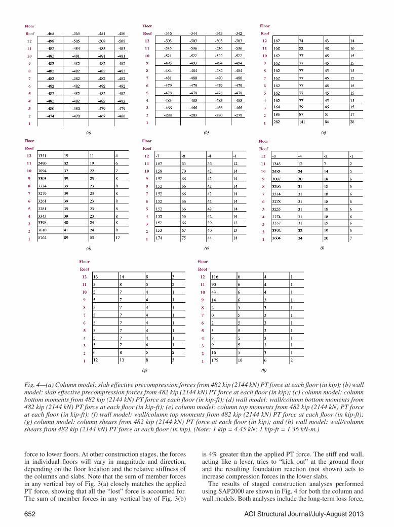
The results of staged construction analyses performed using SAP2000 are shown in Fig. 4 for both the column and wall models. Both analyses include the long-term loss force,
Fig. 4—(a) Column model: slab effective precompression forces from 482 kip (2144 kN) PT force at each floor (in kip); (b) wall model: slab effective precompression forces from 482 kip (2144 kN) PT force at each floor (in kip); (c) column model: column bottom moments from 482 kip (2144 kN) PT force at each floor (in kip-ft); (d) wall model: wall/column bottom moments from 482 kip (2144 kN) PT force at each floor (in kip-ft); (e) column model: column top moments from 482 kip (2144 kN) PT force at each floor (in kip-ft); (f) wall model: wall/column top moments from 482 kip (2144 kN) PT force at each floor (in kip-ft); (g) column model: column shears from 482 kip (2144 kN) PT force at each floor (in kip); and (h) wall model: wall/column shears from 482 kip (2144 kN) PT force at each floor (in kip). (Note: 1 kip = 4.45 kN; 1 kip-ft = 1.36 kN-m.)
ACI Structural Journal/July-August 2013 653
so the effective prestress in each floor would be 482 kip (2144 kN) if no force redirection occurred. For simplicity, model behavior comparisons will be based on compres-sion forces in the middle span (model right-hand bay). Figure 4(a) shows that, for the column model, the effective prestress force has been redirected away from the second floor and roof—approximately 3% and 7% of the desired force, respectively. All other floors have effective precom-pression forces very close to or slightly above the effective force of 482 kip (2144 kN). This is easily explained. At inter-mediate floors, the PT force that is diverted away to lower floors gets replaced by PT force diverted in from higher floors. At the slab immediately above the foundation, the PT force diverted into foundations is greater than the replace-ment force diverted in from floors above. At the roof slab, force is diverted away to lower slabs but no force is diverted in from above. Should PT design forces be increased at loca-tions where PT slab compression force is diverted away? This is discussed in the following. For the wall model, as shown in Fig. 4(b), slab precompression is directed away by approximately 42% and 29% for the second floor and the roof, respectively. The third floor shows a small precom-pression loss of approximately 3%, while all other floors have effective precompression forces equal to or greater than the tendon effective force. The highest value is 503 kip (2237 kN) at the 11th floor—approximately 4% greater than the tendon effective force. Compared to the column model, the stiffer restraints of the wall model divert more of the PT force into the foundations, significantly reducing PT at the second and third floors. Delayed engagement of one or both stiff members through delayed pour strips or tempo-rary slip connections can increase the amount of precom-pression force staying in the slab.11-13 Slab ends being drawn inward by PT forces also cause the stiff end walls to rotate inward, “squeezing” middle floors when floors above them are post-tensioned.
The moments in kip-ft at the bottom of the columns at each floor are shown in Fig. 4(c) for the column model and in Fig. 4(d) for the wall model. These moments reflect only the effect of horizontal PT forces, not gravity slab flex-ural forces. Columns and walls in both models experience moments when being drawn inward by the staged PT at each floor. When the PT force is applied at one story only, the moments of columns at lower floors change magnitude and direction, depending on whether the floor being tensioned is one, two, or more levels above the point of interest and depending on the relative stiffness of the columns, walls, and slabs. As a result, some of the moments “wash out” rather than cumulate at intermediate stories during staged construc-tion. In the end, this results in fairly uniform moments at those stories. In contrast, first-story columns experience significantly more moment (and shear) than other floors, which agrees well with the precompression loss seen at the first floor, as shown in Fig. 4(a). Moments at end columns are also greater than those at inner columns due to the greater horizontal movements at building ends. Figure 4(d) shows that stiff walls experience moments 20 times larger than those at corresponding columns in the other model, reflecting the greater redirection of precompression forces at lower and roof slabs.
Permanent moments at the column top are shown in Fig. 4(e) for the column model and Fig. 4(f) for the wall model. Typically, lower moments are observed at the column top than at the column bottom. Figures 4(g) and (h) show the
column shear forces for the column and wall models, respec-tively. Shear forces are generally greater near the founda-tion and near the roof than at typical intermediate floors, again reflecting the offsetting shear forces as PT forces are diverted away from some slabs and into other slabs at different construction stages. Compared to the column model, Fig. 4(h) shows that stiff shear walls attract signifi-cantly more shear than their column model counterparts.
Appropriate design treatment for the shears and moments induced by PT force diversion can be inferred from the code approach to secondary actions. In post-tensioned structures, hyperstatic (or secondary) actions develop where supports constrain free movement of the post-tensioned member. Per ACI 318-11,5 Section 18.10, secondary forces are included in load combinations for required strength with a load factor of 1.0. Typically, PT design considers individual floors, so secondary actions are only coming from vertical constraints. However, moments and shears due to PT force diver-sion during construction of a post-tensioned building are secondary actions as well, even though they are generally overlooked in analysis and design. The secondary actions resulting from diversion of horizontal PT forces should be considered in both service and strength load combinations with a load factor of 1.0.
Secondary shear and moment values from PT diversion vary with time. They change at each stage of construction based on PT forces before losses. They act on the completed structure based on PT forces before losses and differ again for the completed structure based on PT forces after losses. Which case or cases should be considered when designing the permanent structure? It depends. Secondary forces, as considered in the code and typically applied in design, are those present after construction is completed and long-term PT losses have occurred. This makes sense because using the smallest horizontal PT force would also mean using the smallest helpful load-balancing effect. That would result in the worst slab, column, and wall moments and shears under factored gravity loads, which would normally control slab design. So, slab, column, and wall moments and shears from the secondary effects of PT redirection should use effective PT (after long-term losses) in both serviceability and strength load combinations where they add to gravity effects. The completed structure initial PT case should also be checked; a larger load-balancing effect from greater PT would reduce net gravity forces, but where secondary PT force increases enough to more than compensate for the change, it could control the design. During construction stages, larger maximum and minimum effects may occur, but the conditions are temporary, the applied PT forces are well-controlled, and floor superimposed dead loads and live loads are usually not yet present. This does not mean construction stage conditions can be ignored because load paths are different in an incomplete structure. For example, the presence or absence of a slab above a floor of interest will affect the distribution of slab end moments along columns. Having less axial load on incomplete columns and walls can affect their moment or shear capacity; the reduced member capacity should be considered when performing construc-tion stage checks.
For the special cases that follow, in the interest of brevity, general conclusions are provided based on the slab effec-tive precompression force patterns rather than presenting and discussing tabulated shear and moment forces for the column and wall. However, the effects of these cases on

654 ACI Structural Journal/July-August 2013
columns and walls should be incorporated in designs using the method described in this paper.
Low-rise buildingsFigure 5 shows the axial forces for both one- and two-
story post-tensioned buildings for both models. For the one-story building, approximately 14% and 60% of the slab precompression is diverted away for the column and wall models, respectively. It clearly shows that stiffer restraints divert more axial force to the foundations at grade. For the two-story column model, both floors have axial forces within 10% of the effective force. However, the two-story wall model shown in Fig. 5(b) has more than 30% of precompres-sion diverted away at both floors. The potential for this much reduction in effective precompression must be addressed in the design, as is discussed in the following.
Non-post-tensioned floor in the middleIn multi-story buildings, it is not uncommon to have an
isolated floor at midheight that is not post-tensioned. For example, a mechanical floor may require a conventionally reinforced slab-and-beam system to resist heavy superim-posed dead and live loads of uncertain distribution. To simu-late this situation, the PT force was not applied at the eighth-floor slab for both models.
Figure 6 shows that precompression is reduced at the seventh floor immediately below the non-PT floor by approx-imately 12% and 30% for the column and wall models, respectively. This is due to diversion of seventh-floor PT force to lower levels not being “made up” by diversion of PT from upper levels into the seventh floor. The PT forces from floors above compress the non-PT eighth floor instead. As seen in other cases, a greater stiffness of vertical elements causes a greater reduction in precompression for the story below the non-PT floor.
Fig. 5—(a) Column model: slab effective precompression from 482 kip (2144 kN) PT force at each floor, low rise (in kip); and (b) wall model: slab effective precompression from 482 kip (2144 kN) PT force at each floor, low rise (in kip). (Note: 1 kip = 4.45 kN.)
Fig. 6—(a) Column model: slab effective precompression from 482 kip (2144 kN) PT force at each floor if no PT at eighth floor (in kip); and (b) wall model: slab effective precompression from 482 kip (2144 kN) PT force at each floor if no PT at eighth floor (in kip). (Note: Eighth floor shown dashed for clarity; 1 kip = 4.45 kN.)

ACI Structural Journal/July-August 2013 655
Soft storyFigure 7 shows slab effective precompression forces for
both models if the eighth story is made taller and “softer.” The floor of the soft story has 6% of its precompression diverted away in the column model and 13% in the wall model. This is due to an imbalance between the amount of PT force being diverted away from each slab and the amount being diverted in. Compared with the models without a soft story shown in Fig. 4(a) and (b), a higher percentage of the axial force remains in the ninth-floor slab when this floor is post-tensioned and much less axial force is transferred to the
eighth floor. As a result, the slab right above the soft story retains precompression forces 3% and 12% higher than the tendon effective force of 482 kip (2144 kN) in the column and wall models, respectively. The converse is also true: At a stiffer-than-typical story, the floor of that stiff story will have more precompression force and the floor above will have less.
Non-PT floors at lower levelsFigure 8 shows slab precompression forces for both
models when the first two stories are not post-tensioned.
Fig. 7—(a) Column model: slab effective precompression from 482 kip (2144 kN) PT force at each floor if soft story at eighth floor (in kip); and (b) wall model: slab effective precompression from 482 kip (2144 kN) PT force at each floor if soft story at eighth floor (in kip). (Note: Soft-story columns shown bold for clarity; 1 kip = 4.45 kN.)
Fig. 8—(a) Column model: slab effective precompression from 482 kip (2144 kN) PT force at each floor if no PT at first and second floors (in kip); and (b) wall model: slab effective precompression from 482 kip (2144 kN) PT force at each PT floor if no PT at first and second floors (in kip). (Note: Non-PT slabs shown dashed for clarity; 1 kip = 4.45 kN.)

656 ACI Structural Journal/July-August 2013
Because the non-PT slabs provide much less restraint than stiff foundations, the amount of PT force diverted to them is much less than that delivered to stiff foundations in the all-PT case. The effective precompression forces on other floors behave similarly to the all-PT case.
RECOMMENDATIONSTwo typical criteria controlling the design of PT slabs are
minimum average precompression and net tensile stress. Design methodologies are generally based on the assump-tion that slab precompression is equal to the effective tendon force at that level. For multi-story PT slab construction of consistent floor design and story height, at most floors, the average slab precompression will be close to the PT tendon effective force. However, special attention is required for slabs just above the foundation, at the top, and at changes in conditions such as story height and amount of PT. This study shows that the precompression force at some floors can be significantly less than the PT tendon effective force. Strate-gies to consider in such cases include isolation, compensa-tion, calculation, and judgment.
Isolation makes the best sense where the structural config-uration would otherwise lead to precompression losses so large as to be both costly and, if not carefully handled in design and construction, potentially damaging. For example, the one-story model with stiff walls shows an approximate 60% precompression loss. Increasing PT to compensate for PT precompression force diverted into the founda-tions as wall shear and overturning would be expensive. It would be preferable to introduce sliding joints or delayed pour strips that allow PT to be tensioned without tugging against opposing walls. Once PT tensioning is completed, the delayed pour strips can be filled or sliding joints can be locked to engage the walls. Note that once the slab is locked to the walls, forces can still be generated by subsequent strains from shrinkage, creep, and temperature changes. This paper does not address those behaviors. Another impor-tant strategy to isolate wall behavior from post-tensioned member behavior is to simply group shear walls in a central location if the design permits. This allows slab ends to move more freely without introducing special pour strips or joints. This preferred approach was intentionally not followed for the model in this study to better demonstrate the PT diver-sion effects of shear walls placed at building ends.
Compensation means the application of a simple method to address anticipated precompression loss. For example, recognizing that the topmost slab can tend to have less precompression, some engineers simply specify 10% higher prestress levels at the roof as compensation. If the same slab thickness and drape is applied at all floors, note that increasing applied PT to provide more horizontal compres-sion will mean an increase in vertical load-balancing forces and associated secondary effects. These additional balancing forces may or may not be a concern, depending on the frac-tion of dead load being balanced and the nature of other loads being applied. If the compensation approach calls for 20 or 30% additional PT force, it is likely that tendon drapes will require flattening to avoid overbalancing, and increased forces on vertical elements and adjacent slabs will require careful review.
Calculation means applying first principles to member design, considering anticipated values of PT tendon effec-tive force and slab effective precompression force at several stages. The classic approach assumes that precompression is
equal to the effective tendon force (after losses) in all spans and determines concrete slab service tension and compres-sion stresses as follows
P MA S
s = ± (1)
where P is the tendon effective force; A is the design strip cross-section area; S is the section modulus; and M is the total moment at the governing service-load combination. Note that the moment M may include the moments from dead, live, and lateral loads and the vertical component of PT forces.
In this study, tendon effective force differs from slab precompression force, so different PT forces should be used to calculate the two different terms in the equation for slab stresses. This may affect the selection of compensation strat-egies. For M/S, the tendon force (not the slab precompres-sion force) is used to calculate moments induced by load-balancing forces from the tendon profile. However, the slab precompression force P in P/A should reflect forces present after diversion occurs using a method such as that presented in this paper. For a constant PT force and tendon profile, diversion of precompression force affects only the P/A term, but increasing PT force in an effort to compensate for force diversion affects both terms. Therefore, keeping below a specified flexural stress limit may take a smaller PT increase than suggested by the percentage change of precompression loss. In addition, it may be necessary to consider the different tendon forces and corresponding slab compression stresses at several construction and preloss complete-frame stages.
PT force diversion during construction of a post-tensioned building results in secondary actions in both horizontal and vertical elements, and slab moments due to PT force diver-sion should be included in the calculation of the moment M. Where secondary actions due to PT force diversion add to gravity load effects, the actions based on tendon initial force should be used in both service and strength load combinations with a load factor of 1.0. This will affect both load-balancing moments and slab precompression. Where secondary actions from PT force diversion do not add to gravity effects, the actions should be based on tendon effec-tive force (after long-term losses). It is strongly recom-mended that the secondary actions due to PT force diversion be explicitly incorporated in ACI 318-11.5
Judgment is the recognition that concrete is a nonlinear material and that concrete design is a mixture of science and art. The studies reported in this paper use linear elastic models with time-invariant materials. Changing the assump-tions by introducing cracked section properties for columns and walls, different foundation stiffness conditions, and creep and shrinkage behavior in columns, walls and slabs can yield significantly different short-term and long-term results. For example, cracking and creep would “smooth out” force differences. It would be impractical and unnec-essary to design for an envelope of forces from worst-case scenarios. However, it is prudent to investigate the range of “what-ifs” and provide designs that respond in an acceptable, safe, and ductile fashion if the extreme conditions occur. For instance, when checking for column or wall shears during construction upon PT tensioning, it may be appropriate to use a smaller gravity load factor than when checking for the completed building (PT effects should use a factor of 1.0 in

ACI Structural Journal/July-August 2013 657
any case). It would also be prudent to check that, in the event of overload during construction, the columns and walls are controlled by flexure and not shear.
CONCLUSIONSBased on the aforementioned analyses and discussion,
the effects of story-by-story PT on multi-story buildings are summarized as follows:
1. A portion of the tendon force applied at a particular floor to a post-tensioned slab is diverted to the floors below by columns and walls acting in shear and flexure. Increased stiff-ness of vertical members results in more force being diverted.
2. For multi-story buildings, the roof and the first PT slab above the foundation typically experience precompres-sion loss that may be significant for design. Stiffer vertical columns or walls and stiffer restraints by foundations cause greater precompression losses. Increasing the story height just above foundations can be beneficial in reducing precom-pression loss.
3. Conventionally reinforced concrete slabs at several levels between foundations and the first PT slabs can improve the amount of precompression remaining in the PT slabs and reduce PT-induced moments and shears in columns and walls.
4. Diversion of precompression away from a slab can be very large for PT slabs running between two stiff vertical members.
5. Temporary and permanent (although time-dependent) moments and shears can be induced in both horizontal and vertical elements during stages of construction. The forces are additive to those due to gravity and lateral loads and should be treated as secondary forces due to horizontal PT. When the secondary forces are in addition to those due to gravity and lateral loads, the effects based on tendon initial force should be included in load combinations with a load factor of 1.0. Otherwise, the forces based on tendon effective force (after losses) should be used. Columns and slabs designed without considering those additional effects could potentially experi-ence distress, including unacceptable cracking.
6. For low-rise post-tensioned buildings, a significant frac-tion of the precompression force can be lost through diver-sion to foundations through columns and walls. Isolating slabs from walls and/or increasing PT forces to compensate are recommended strategies.
7. The PT slab immediately below a conventionally reinforced concrete floor inserted within a multi-story post-tensioned building is similar to a roof slab condition; precompression forces are smaller because it loses force to lower floors, but no compression forces are diverted into it from the floor above.
8. When a soft story is present, slab compression force will be larger in the upper floor and smaller in the lower floor. Consider the need for compensation measures to address reduced precompression in the slab at the bottom of the soft story.
9. When calculating stresses under service-load combi-nation, use tendon effective force when determining load balancing and bending moments from PT, but use the slab effective precompression forces, as determined in this paper, to calculate the average compression P/A.
10. When checking strength, it is necessary to look at both the initial conditions using tendon initial force and forces from restraint during construction stages and long-term conditions using tendon effective force and corresponding forces from restraint. Different load combinations may govern, depending on the location in the structure.
11. Modeling concrete structures has its limitations and engineering judgment is needed to evaluate the significance of cracked sections, creep, shrinkage, and detailing for ductile behavior.
To design post-tensioned concrete buildings, it is strongly recommended that an analytical model be created to study the effects of story-by-story PT on both slabs and vertical supports, especially for buildings with severe restraints, such as shear walls.
It should be noted that the aforementioned conclusions are based on results from linear elastic analytical models. Further field or experimental studies are recommended to validate the findings of this paper in actual PT concrete construction.
REFERENCES1. Aalami, B. O., “Load Balancing: A Comprehensive Solution to
Post-Tensioning,” ACI Structural Journal, V. 87, No. 6, Nov.-Dec. 1990, pp. 662-670.
2. Kelley, G. S., “Resolving Field Problems in Unbonded Post-Tensioning Installation,” Concrete International, V. 25, No. 4, Apr. 2003, pp. 75-81.
3. Aalami, B., “Hyperstatic (Secondary) Actions in Prestressing and Their Computation,” PTI Technical Note #7, 1998, 10 pp.
4. Bommer, A., “Complete Secondary (Hyperstatic) Effects,” PTI Journal, V. 2, No. 1, Jan. 2004, pp. 53-64.
5. ACI Committee 318, “Building Code Requirements for Structural Concrete (ACI 318-11) and Commentary,” American Concrete Institute, Farmington Hills, MI, 2011, 503 pp.
6. Fintel, M., and Ghosh, S. K., “Case Study of Effects of Post-Tensioning the Beams in a 45-Story Building,” ACI Journal, V. 75, No. 5, May 1978, pp. 184-191.
7. PCI Design Handbook—Precast and Prestressed Concrete, fifth edition, Precast/Prestressed Concrete Institute, Chicago, IL, 1999, 690 pp.
8. Aalami, B., “Prestressing Losses and Elongation Calculations,” ADAPT Technical Note, Issue T9-04, Oct. 1998, 16 pp.
9. Kelley, G. S., “Prestress Losses in Post-Tensioned Structures,” PTI Technical Note #10, Sept. 2000, 6 pp.
10. “Post-Tensioned Concrete Floors—Design Handbook,” Technical Report 43, The Concrete Society, Camberley, Surrey, UK, 2005, 110 pp.
11. Guo, G.; Lin, K.; and Joseph, M. L., “Pour Strip Design in Post-Tensioned Buildings Using Unbonded Tendons,” PTI Journal, V. 6, No. 2, July 2008, pp. 21-28.
12. Bondy, K. B., “Shortening Problem in Post-Tensioned Concrete Buildings,” SEAOC Seminar Proceedings—Design Review and Inspection of Prestressed Concrete Building Projects, Jan. 1989, pp. 1-19.
13. Aalami, B. O., and Barth, F. G., Restraint Cracks and Their Miti-gation in Unbonded Post-Tensioned Building Structures, Post-Tensioning Institute, Farmington Hills, MI, 1988, 49 pp.

658 ACI Structural Journal/July-August 2013
NOTES: