achieving high efficiency at 2010 emissions · pdf fileradial inflow turbine ... axial impulse...
TRANSCRIPT
Heavy Duty Truck Engine
Achieving High Efficiency at 2010 Emissions
Christopher R. Nelson Cummins Inc.
DEER Conference August 23rd, 2006
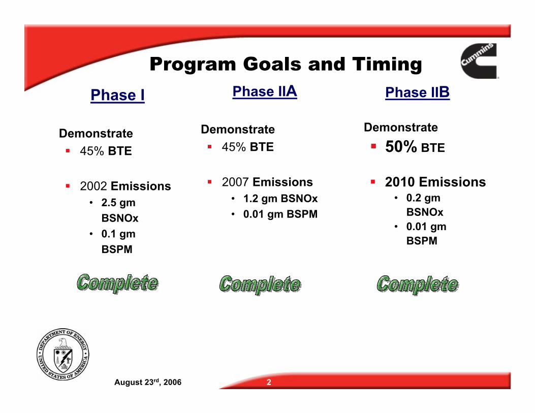
Program Goals and Timing
Phase I Phase IIA
Demonstrate Demonstrate
� 45% BTE � 45% BTE
� 2002 Emissions � 2007 Emissions • 2.5 gm • 1.2 gm BSNOx
BSNOx • 0.01 gm BSPM
• 0.1 gm
BSPM
Phase IIB
Demonstrate � 50% BTE
� 2010 Emissions • 0.2 gm
BSNOx • 0.01 gm
BSPM
August 23rd, 2006 2
August 23rd, 2006 3
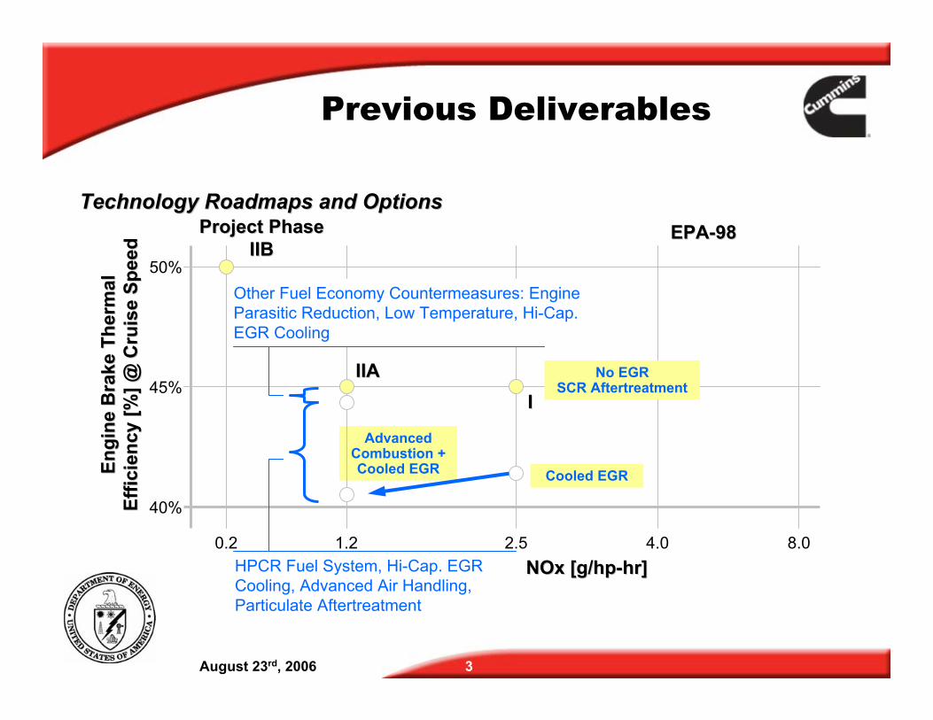
Advanced Combustion + Cooled EGR
0.2 1.2 2.5 8.0
45%
50%
40%
Project PhaseProject PhaseIIBIIB
IIAIIAII
NOx [g/hpNOx [g/hp--hr]hr]
Engi
ne B
rake
The
rmal
Engi
ne B
rake
The
rmal
Effic
ienc
y [%
] @ C
ruis
e Sp
eed
Effic
ienc
y [%
] @ C
ruis
e Sp
eed
4.0
EPAEPA--9898Technology Roadmaps and OptionsTechnology Roadmaps and Options
Cooled EGR
HPCR Fuel System, Hi-Cap. EGR Cooling, Advanced Air Handling, Particulate Aftertreatment
Other Fuel Economy Countermeasures: Engine Parasitic Reduction, Low Temperature, Hi-Cap. EGR Cooling
No EGR SCR Aftertreatment
Previous Deliverables
1.2 2.5 4.0
EPAEPA--9898
August 23rd, 2006 4
0.2 8.0
45%
50%
40%
Project PhaseProject PhaseIIBIIB
IIAIIAII
NOx [g/hpNOx [g/hp--hr]hr]
Max
imum
Eng
ine
Bra
keM
axim
um E
ngin
e B
rake
Th
erm
al E
ffici
ency
[%]
Ther
mal
Effi
cien
cy [%
]
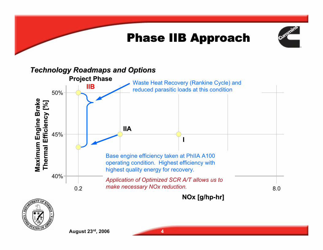
Technology Roadmaps and OptionsTechnology Roadmaps and OptionsWaste Heat Recovery (Rankine Cycle) and reduced parasitic loads at this condition
Base engine efficiency taken at PhIIA A100 operating condition. Highest efficiency with highest quality energy for recovery.
Application of Optimized SCR A/T allows us to make necessary NOx reduction.
Phase IIB Approach
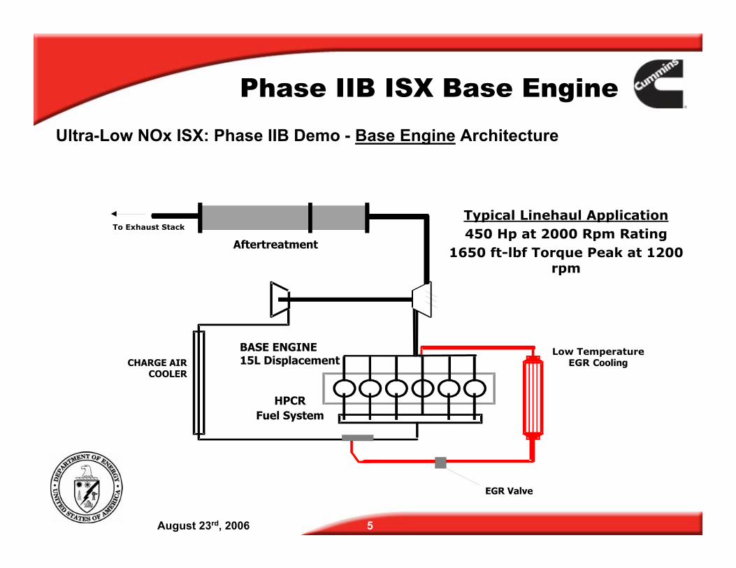
Phase IIB ISX Base Engine Ultra-Low NOx ISX: Phase IIB Demo - Base Engine Architecture
CHARGE AIR COOLER
BASE ENGINE 15L Displacement
Low Temperature EGR Cooling
Aftertreatment
HPCR Fuel System
To Exhaust Stack Typical Linehaul Application 450 Hp at 2000 Rpm Rating
1650 ft-lbf Torque Peak at 1200 rpm
EGR Valve
August 23rd, 2006 5
Aftertreatment
NOx Reduction Technique � Urea-SCR
• A Urea-SCR Aftertreatment System operating at 85% Efficiency was assumed present in the high-efficiency test and demonstration
PM Reduction Technique � Very similar to technology applied to Phase IIA. � Robust RPF (DOC and PF)
• An RPF operating at 90% Efficiency was assumed present in the high efficiency test and demonstration.
August 23rd, 2006 6
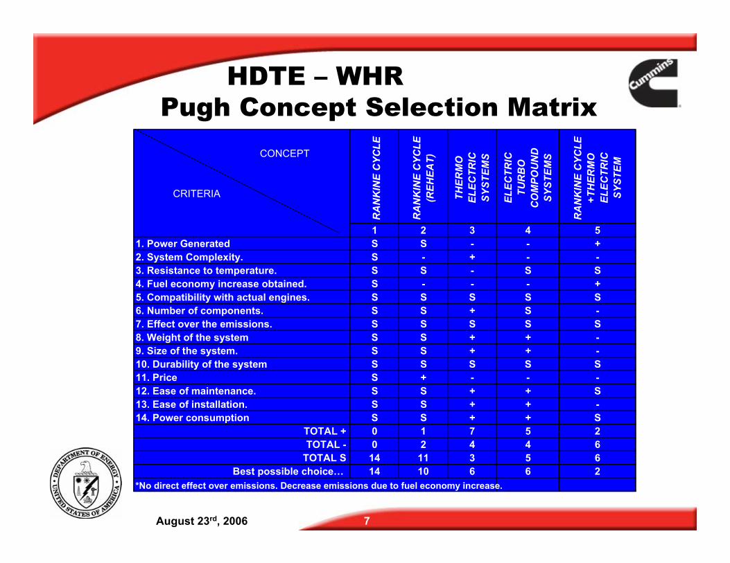
HDTE – WHR Pugh Concept Selection Matrix
CONCEPT
CRITERIA
RA
NK
INE
CYC
LE
RA
NK
INE
CYC
LE
(REH
EAT)
THER
MO
ELEC
TRIC
SYST
EMS
ELEC
TRIC
TUR
BO
CO
MPO
UN
DSY
STEM
S
RA
NK
INE
CYC
LE
+TH
ERM
OEL
ECTR
ICSY
STEM
1 2 3 4 5 1. Power Generated S S - - + 2. System Complexity. S - + - -3. Resistance to temperature. S S - S S 4. Fuel economy increase obtained. S - - - + 5. Compatibility with actual engines. S S S S S 6. Number of components. S S + S -7. Effect over the emissions. S S S S S 8. Weight of the system S S + + -9. Size of the system. S S + + -10. Durability of the system S S S S S 11. Price S + - - -12. Ease of maintenance. S S + + S 13. Ease of installation. S S + + -14. Power consumption S S + + S
TOTAL + 0 1 7 5 2 TOTAL 0 2 4 4 6
TOTAL S 14 11 3 5 6 Best possible choice… 14 10 6 6 2
*No direct effect over emissions. Decrease emissions due to fuel economy increase.
August 23rd, 2006 7
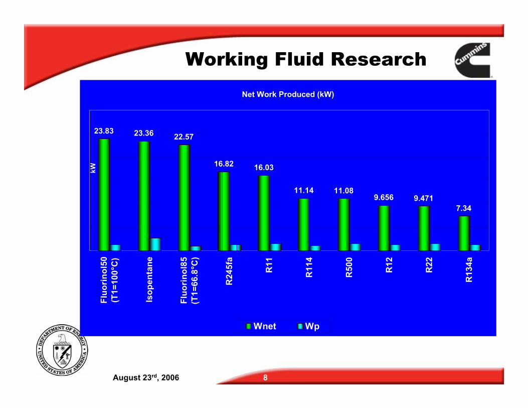
Working Fluid Research
Net Work Produced (kW)
23.83 23.36 22.57
16.82 16.03
11.14 11.08 9.656 9.471
7.34
kW
Wnet Wp
August 23rd, 2006 8
Fluo
rinol
50(T
1=10
0°C
)
Isop
enta
ne
Fluo
rinol
85(T
1=66
.8°C
)
R24
5fa
R11
R11
4
R50
0
R12
R22
R13
4a
Fluorinol-50
Fluorinol or 2,2,2 Trifluoroethanol and water � CAS No. 75-89-8 � Molecular Weight 100.04 � Chemical Formula – F3CCH2OH � Flammable Liquid/Vapor � More toxic than Ethlyene Glycol � Used in previous ORC DoE demonstration
Excellent heat transfer properties with a high thermal stability - >550F
Fluorinol-50 (50-50 molal mix of Fluorinol and Water) provided the best performance -
August 23rd, 2006 9
August 23rd, 2006 10
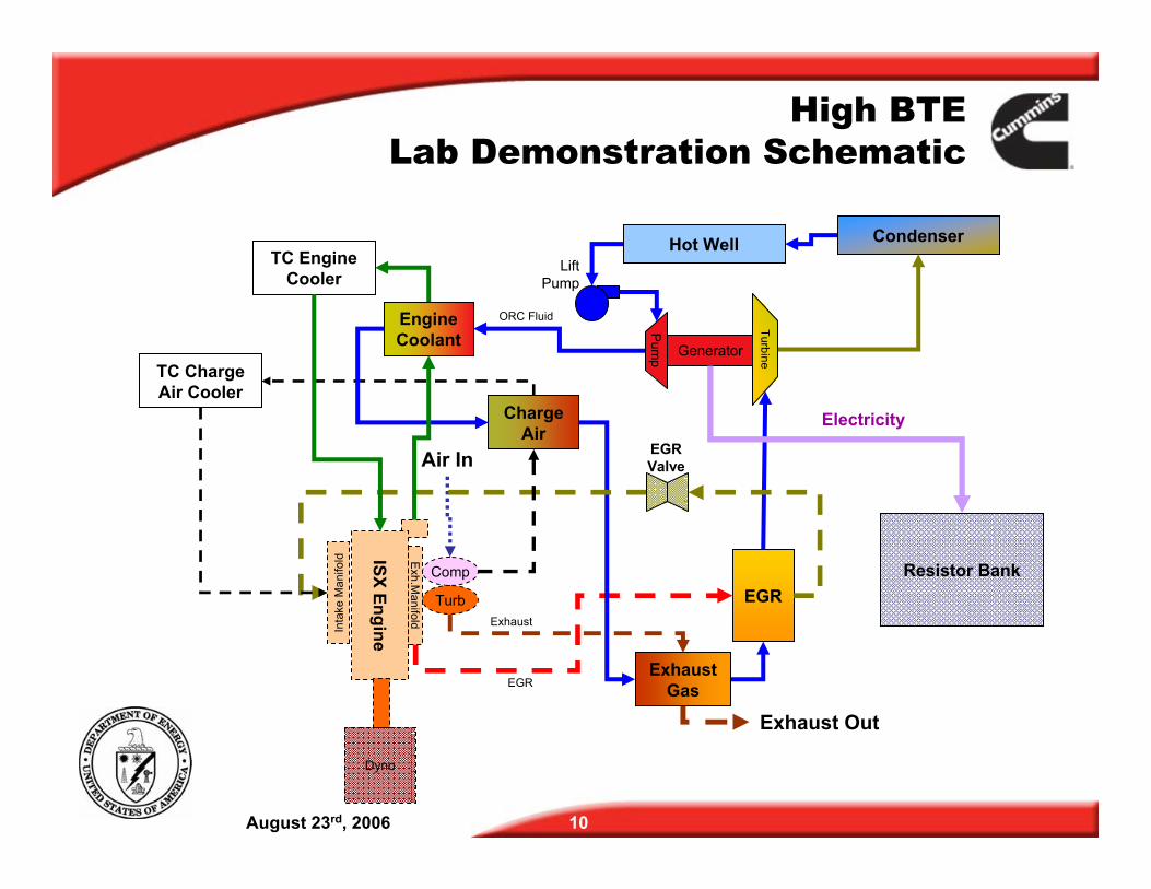
Electricity
ISX Engine Dyno
Comp
Turb
Condenser
EGR
Exh.M
anifold
Charge Air
Exhaust Out
Air In
Exhaust Gas
Generator
Turbine
EGR
Inta
ke M
anifo
ld
Pum
p
Exhaust
Engine Coolant
High BTE Lab Demonstration Schematic
TC Engine Cooler
TC Charge Air Cooler
EGR Valve
Hot Well
Resistor Bank
ORC Fluid
Lift Pump
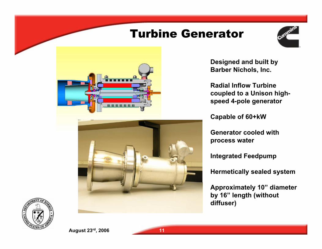
Turbine Generator
August 23rd, 2006 11
Designed and built by Barber Nichols, Inc.
Radial Inflow Turbine coupled to a Unison high-speed 4-pole generator
Capable of 60+kW
Generator cooled with process water
Integrated Feedpump
Hermetically sealed system
Approximately 10” diameter by 16” length (without diffuser)
August 23rd, 2006 12
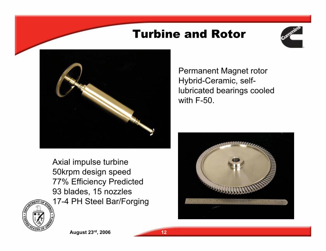
Turbine and Rotor
Permanent Magnet rotor Hybrid-Ceramic, self-lubricated bearings cooled with F-50.
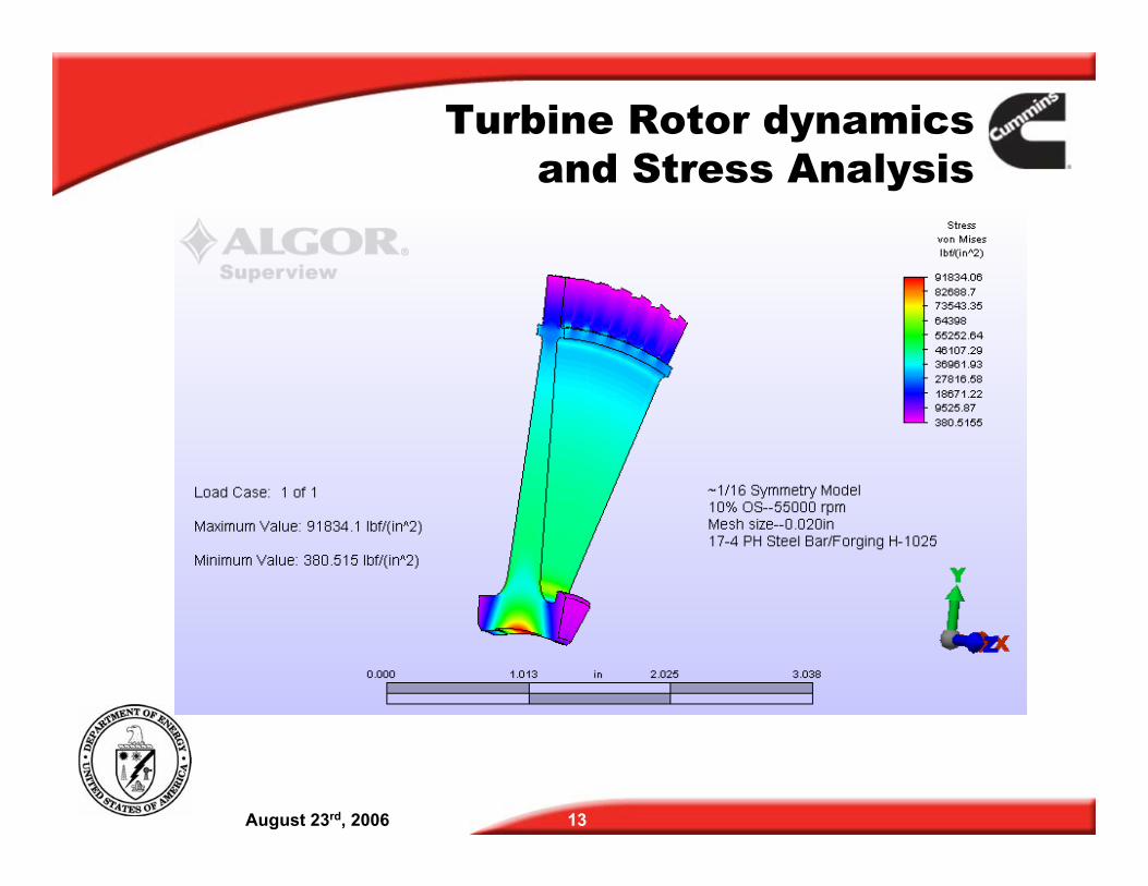
Axial impulse turbine 50krpm design speed 77% Efficiency Predicted 93 blades, 15 nozzles 17-4 PH Steel Bar/Forging
August 23rd, 2006 13
Turbine Rotor dynamics and Stress Analysis
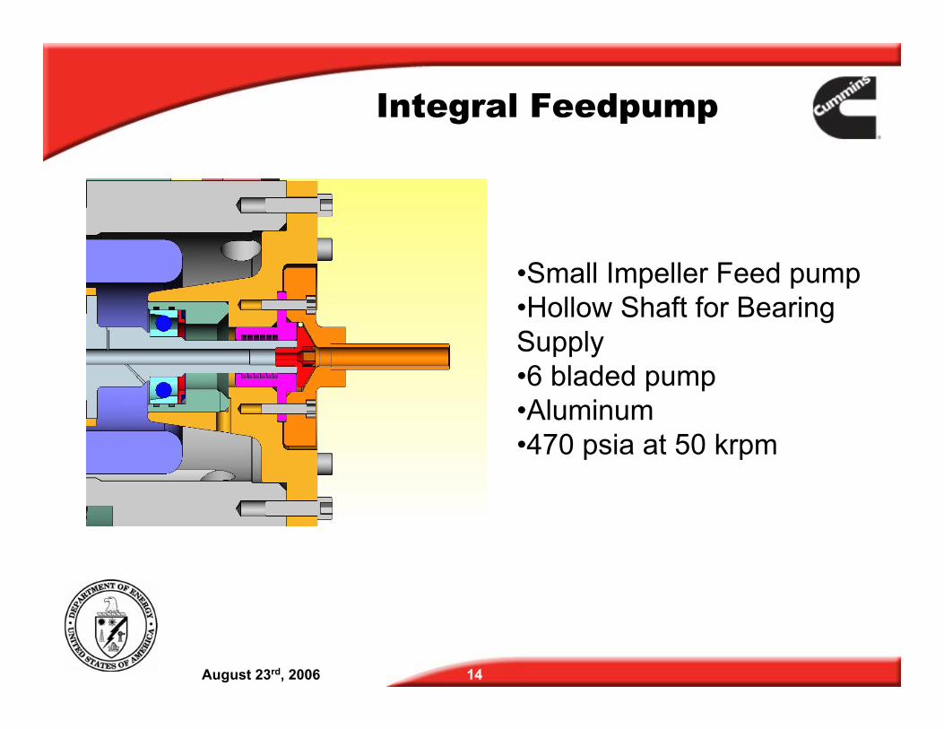
Integral Feedpump
•Small Impeller Feed pump•Hollow Shaft for Bearing Supply •6 bladed pump •Aluminum •470 psia at 50 krpm
August 23rd, 2006 14
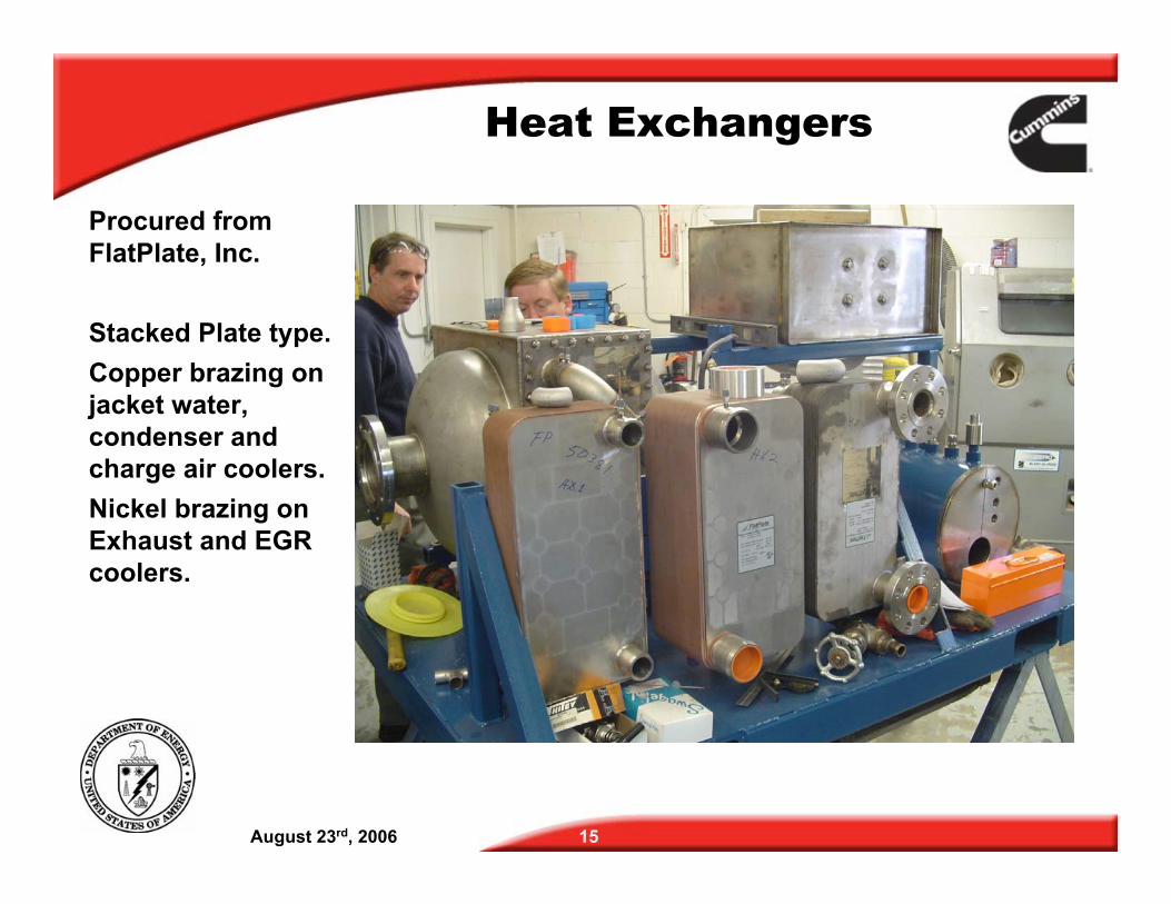
Heat Exchangers
Procured from FlatPlate, Inc.
Stacked Plate type. Copper brazing on jacket water, condenser and charge air coolers. Nickel brazing on Exhaust and EGR coolers.
August 23rd, 2006 15
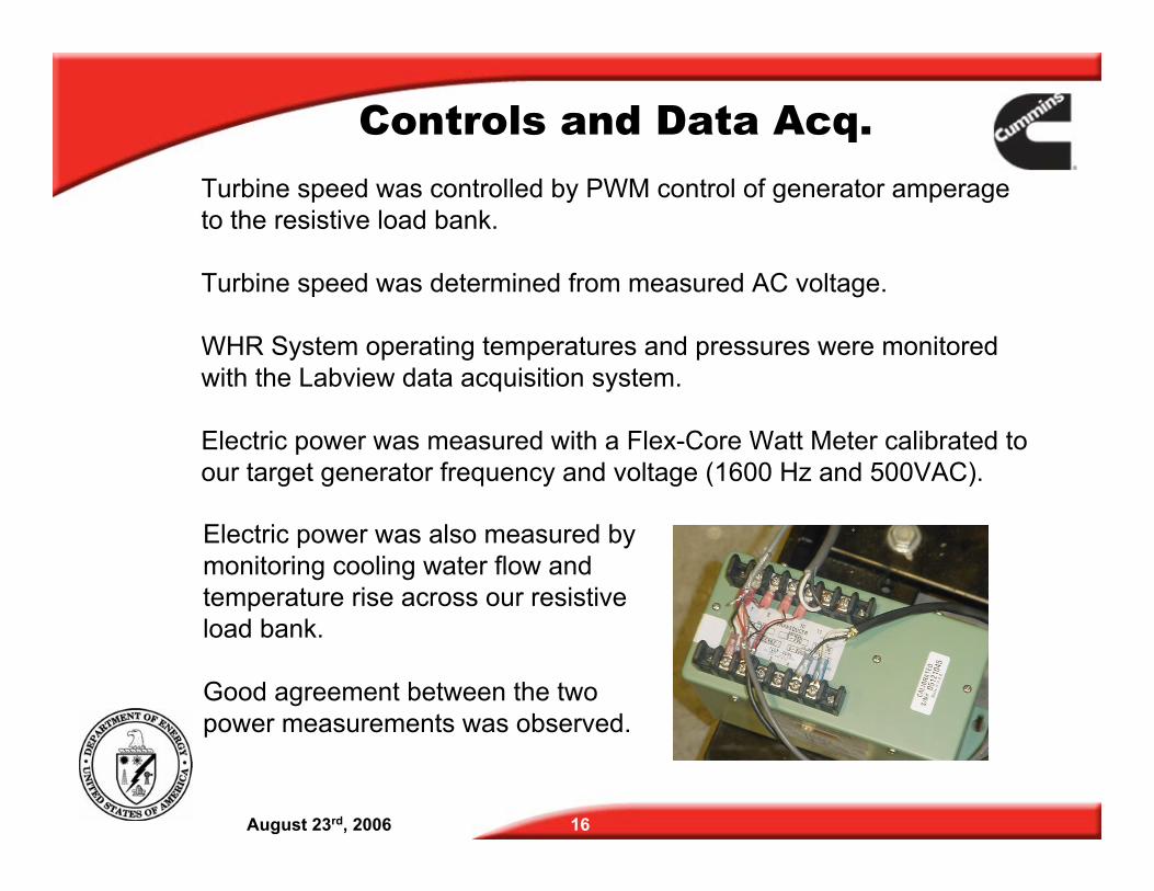
Controls and Data Acq.Turbine speed was controlled by PWM control of generator amperage to the resistive load bank.
Turbine speed was determined from measured AC voltage.
WHR System operating temperatures and pressures were monitored with the Labview data acquisition system.
Electric power was measured with a Flex-Core Watt Meter calibrated to our target generator frequency and voltage (1600 Hz and 500VAC).
Electric power was also measured by monitoring cooling water flow and temperature rise across our resistive load bank.
Good agreement between the two power measurements was observed.
August 23rd, 2006 16
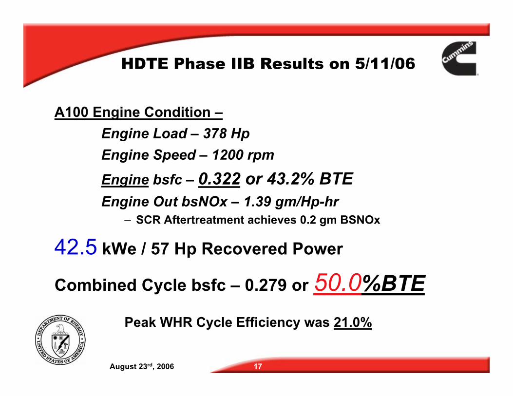
HDTE Phase IIB Results on 5/11/06
A100 Engine Condition – Engine Load – 378 Hp Engine Speed – 1200 rpm
Engine bsfc – 0.322 or 43.2% BTE Engine Out bsNOx – 1.39 gm/Hp-hr
– SCR Aftertreatment achieves 0.2 gm BSNOx
42.5 kWe / 57 Hp Recovered Power
Combined Cycle bsfc – 0.279 or 50.0%BTE
Peak WHR Cycle Efficiency was 21.0%
August 23rd, 2006 17
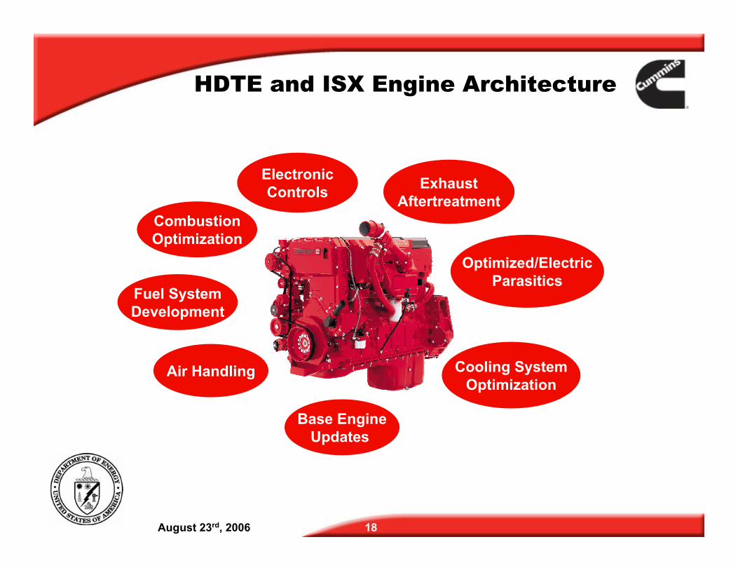
HDTE and ISX Engine Architecture
Combustion Optimization
Electronic Controls Exhaust
Aftertreatment
Fuel System Development
Optimized/Electric Parasitics
Cooling System Optimization
Air Handling
Base Engine Updates
August 23rd, 2006 18
Thanks to our Sponsor!
Cummins Inc. thanks –
The United States Department of Energy
for their support throughout this program
August 23rd, 2006 19