efficiency augmentation of gas turbine cycles
TRANSCRIPT
HEFAT2011
8th
International Conference on Heat Transfer, Fluid Mechanics and Thermodynamics
26 June – 1 July 2011
Pointe Aux Piments, Mauritius
EFFICIENCY AUGMENTATION OF GAS TURBINE CYCLES
Dohmen H. J.*, Schnitzler J. Ph. and Benra F.-K.
*Author for correspondence
Faculty of Engineering Sciences
Department of Mechanical Engineering, Institute of Turbomachinery
University of Duisburg-Essen
Germany
E-mail: [email protected]
ABSTRACT
The efficiency of gas turbine cycles can be enhanced by
application of several methods. In the present contribution, the
four most promising options e.g. compressor cooling,
recuperation, reheating and elevation of turbine inlet
temperature are discussed in detail. The potential of efficiency
augmentation is depicted for all described methods with respect
to the required effort. In addition, it is shown that the
combination of different cycle improvement methods can give
a disproportional high benefit because of upcoming synergy
effects. For the compressor cooling it is worked out that an
unconventional cooling by water injection gives a superior
result over a conventional cooling. Furthermore, as any cooling
of the compression process is accompanied with lower
compressor outlet temperatures a strong potential for
recuperation is provided by combining both methods. Finally,
the obtainable efficiency of a gas turbine is determined for
combination of several enhancement methods.
INTRODUCTION Gas turbines are one of the most common devices in the
field of power generation. Available sizes range from the so
called Micro Gas Turbines (MGT) producing some Kilowatt of
power to Heavy Duty Gas Turbines producing some hundred
Megawatt of power. Today’s designs reflect high running life at
low investment for the high engine-power class. In addition,
gas turbines are flexible with the operating mode and produce
low emissions due to continuous combustion (NOx<10ppm,
CO<15ppm @ 15 Vol.-% residual oxygen at full load) [1].
Therefore, usually no elaborate exhaust gas treatment is
required [2]. A broad spectrum of liquid and gaseous fuels can
be used to operate gas turbines which mostly tolerate changing
fuel compositions. The elementary configurations of gas
turbines which usually have only rotating parts inside comprise
a compact design and power density accompanied by a good
balance and low noise emissions. This potentially contains long
intervals of maintenance (regular maintenance after 6.000 –
8.000 operating hours (oh); overhauling after 40.000 oh; life
time expectation 80.000 oh) which means low maintenance
costs.
Applications for high engine-power class gas turbines can
be found usually in the electricity generation. Two cases of
operation prevail all other applications: stand alone gas turbines
for peak load and gas turbines in combined heat and power
plant applications. The same employments are given for the
MGT’s while the medium size machines very often serve as
movers for other machines.
In the last decade the use of medium and small gas turbines
in the field of cogeneration of heat and power increased
strongly [3]. Peripheral feed of electric energy into the grid has
become a routine matter forced by the usage of renewable
energy resources like wind, sun, organic substances and waste
gases (landfill gas, mine gas, sewer gas, process gas) for
example. The potential for local electric power supply is much
bigger than the currently used portion. As the power output of a
simple cycle gas turbine is only about one third mechanical
energy and two thirds thermal energy this latter energy part of
exhaust gases can be used to increase the efficiency of gas
turbine cycles. For all gas turbines exhaust heat recovery is
feasible at a level of about 650oC. Some examples for external
waste heat recovery are: process energy, process steam,
heating, Organic Rankine Cycles, etc.) [4], [5].
The before mentioned facts outline that simple gas turbine
cycles are not very efficient. Improvements are strongly
recommended in order to provide more opportunities for
application of gas turbines. One method for example is internal
heat recovery. Some of the known advancements of simple gas
turbine cycles are specified as given in Table 1 [1], [6], [7].
Table 1 Advancements of simple gas turbine cycle
Recuperation Reheating
Inlet-chilling Catalytic combustion
Steam-cooled GT Steam injection (STIG)
Spray-inter-cooling (SPRINT) Humid Air turbine (HAT)
Inter-cooling (ICAD) Chemically Recuperated GT
8th International Conference on Heat Transfer, Fluid Mechanics and Thermodynamics
177
The present paper deals only with few of these methods. Out of
the number of opportunities the most promising four have been
selected and evaluated with respect to the required effort and
the achieved result. In addition, combinations of the four
chosen methods are also investigated.
NOMENCLATURE
a Inletkg
kJ Specific work
FS Fuel
ikg
kg Fuel specification
h kgkJ Enthalpy
H kgkJ Fuel heating value
m skg Mass flow
Ma Mach number
p Pa Pressure
Q skJ Heat flux
T K Temperature
Special characters
Air
Fuelkg
kg Fuel feed ratio
Efficiency of heat exchanger Efficiency Relative humidity Pressure ratio
Mixture
ikg
kg Mass ratio of fluid composition mixture
Loss coefficient according to Levebre
Subscripts
0 Reference state
1 Inlet of gas turbine component
2 Outlet of gas turbine component
c Cold side
cold Cold pressure drop losses
C Compressor
CC Combustion chamber
DF Diffusor
Fu Fuel
h Hot side
Hex Heat exchanger
i Inferior, index of gas turbine component
index of fluid composition mixture
IC Inter cooling
ID Inlet duct
m Middle
M KkgkJ
Molar mass
max Maximum
mech Mechanical losses
min Minimum
Mix Mixture
R KkgkJ
Universal gas constant
real Real
s ,KkgkJ Isentropic, superior
t Total
T Turbine
th Thermal
theor Theoretic
W Water
WI Water injection
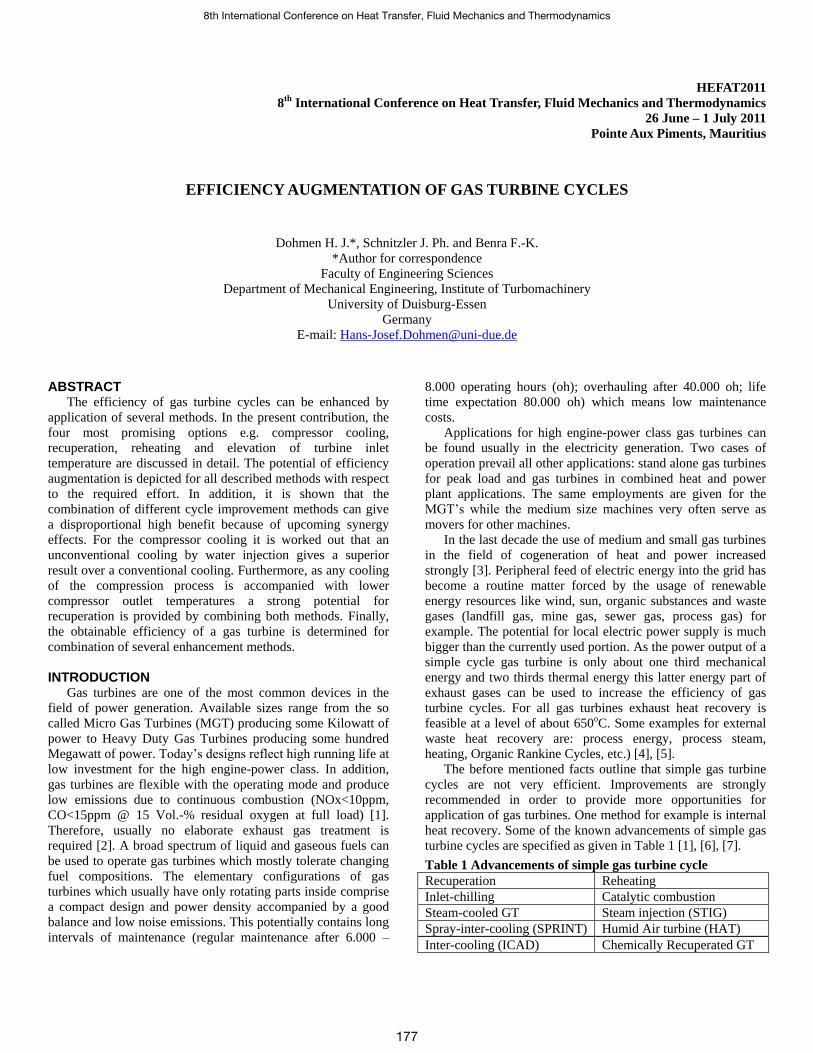
GAS TURBINE CYCLE ASSESSMENT Simple cycle as basis for comparison
Simple gas turbine cycles are characterised by the scheme
depicted in Figure 1. Due to its simplicity and the limits
concerning the technical boundary conditions the efficiency of
the cycle is lower than 30% for small machines and not higher
than 39% for big machines. Nowadays we are not able to afford
such low efficiencies in the field of power generation.
Figure 1 Simple gas turbine cycle
Independent of the method to improve the efficiency of
such a basic cycle the included parts (inlet filter, compressor,
combustion chamber and turbine) must be high efficient
components. The thermal efficiency and the specific work
output of the cycle can be calculated using the following
equations:
C
Cs
tt
tstCs
h
h
hh
hh
12
12 (1)
realFu
theorFu
srealFu
stheorFu
CCm
m
Hm
Hm
(2)
2 1
2 1
t t TTs
t s t Ts
h h h
h h h
(3)
i
mech
i
i
thH
a
(4)
i mech
i
a a (5)
178
Boundary conditions and fluid properties
On the basis of these well-known relationships describing
the thermodynamic behaviour of gas turbine cycles a Mathcad
based synthesis program has been created in dependence to
Bräunling [8] to determine the thermal efficiency and the
specific work output of the considered cycle. The simple gas
turbine cycle is calculated using the boundary conditions
depicted in figure 1.
The used fluid properties for the gas phase of dry and humid
air as well as the combustion gases are provided by the
formulation VDI 4670 [9] without dissipation at high
temperatures. Whenever the pure substance water is in liquid
state, the fluid properties calculated by the formulation
IAPWS-IF97 [10] are considered. Using ideal gas properties as
a basis for simple gas turbine cycle calculations is a common
and improved method even at high combustion chamber inlet
pressure due to concurrent increase and decrease of temperature
in the compressor and turbine. For gas turbine cycles with a
high amount of evaporated water inside the working fluid and
lower temperatures at equal pressure levels this basis seems to
be not appropriate because of the enlarged imbalance between
ideal gas and real gas properties [11]. However for the
calculations in this paper ideal gas properties are considered for
the fluid in the gas phase and real fluid properties are
considered for the water in liquid state. Further research based
on real fluid properties for air [12] and water in the gas phase is
in the focus of investigations to expose the influence on wet gas
turbine cycles. An appropriate property library for humid air as
real gas is allocated by Kretzschmar et. al. [13].
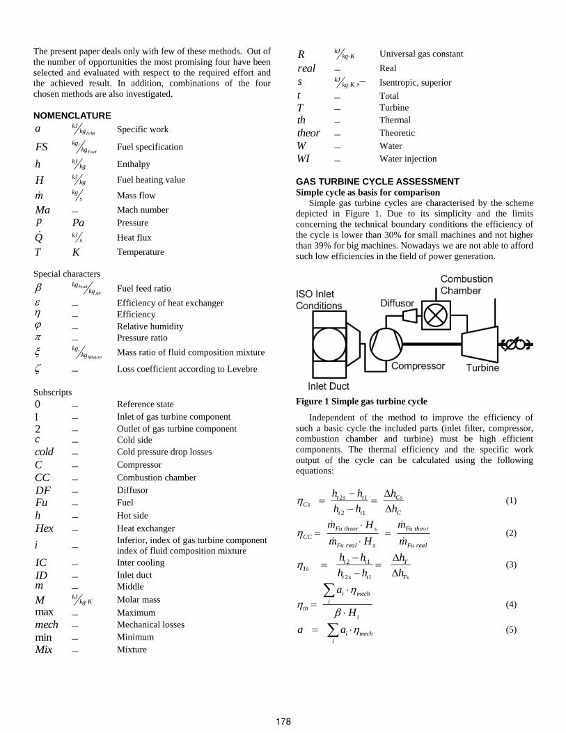
The thermal efficiency of the cycle as a function of
compressor pressure ratio is shown in Figure 2 with the turbine
inlet temperature as a parameter. It is very clear that the
maximum efficiency increases strongly with increasing turbine
inlet temperature. In addition, the maximum of the efficiency
curve can be found at higher compressor ratios for higher
turbine inlet temperatures. From Figure 2 it can be clearly seen
that a high thermal efficiency of a simple gas turbine cycle can
only be achieved with very high turbine inlet temperatures and
high compressor pressure ratios at the same time.
Figure 2 Thermal efficiency of simple gas turbine cycle
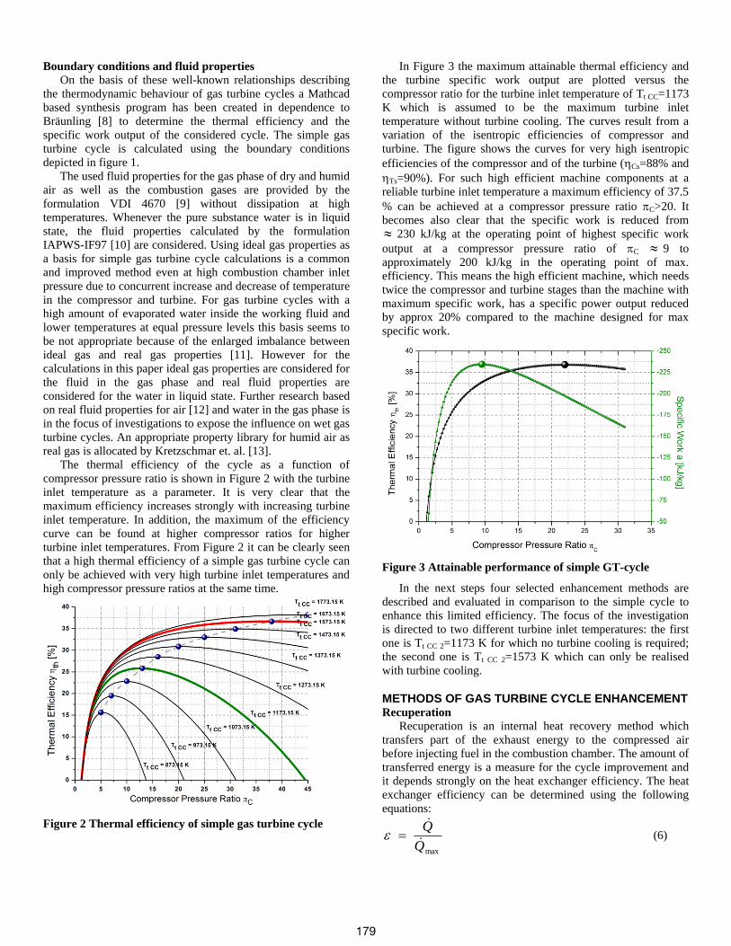
In Figure 3 the maximum attainable thermal efficiency and
the turbine specific work output are plotted versus the
compressor ratio for the turbine inlet temperature of Tt CC=1173
K which is assumed to be the maximum turbine inlet
temperature without turbine cooling. The curves result from a
variation of the isentropic efficiencies of compressor and
turbine. The figure shows the curves for very high isentropic
efficiencies of the compressor and of the turbine (Cs=88% and
Ts=90%). For such high efficient machine components at a
reliable turbine inlet temperature a maximum efficiency of 37.5
% can be achieved at a compressor pressure ratio C>20. It
becomes also clear that the specific work is reduced from
230 kJ/kg at the operating point of highest specific work
output at a compressor pressure ratio of C 9 to
approximately 200 kJ/kg in the operating point of max.
efficiency. This means the high efficient machine, which needs
twice the compressor and turbine stages than the machine with
maximum specific work, has a specific power output reduced
by approx 20% compared to the machine designed for max
specific work.
Figure 3 Attainable performance of simple GT-cycle
In the next steps four selected enhancement methods are
described and evaluated in comparison to the simple cycle to
enhance this limited efficiency. The focus of the investigation
is directed to two different turbine inlet temperatures: the first
one is Tt CC 2=1173 K for which no turbine cooling is required;
the second one is Tt CC 2=1573 K which can only be realised
with turbine cooling.
METHODS OF GAS TURBINE CYCLE ENHANCEMENT Recuperation
Recuperation is an internal heat recovery method which
transfers part of the exhaust energy to the compressed air
before injecting fuel in the combustion chamber. The amount of
transferred energy is a measure for the cycle improvement and
it depends strongly on the heat exchanger efficiency. The heat
exchanger efficiency can be determined using the following
equations:
maxQ
Q
(6)
179
ch QQQ ,minmax (7)
),,( 1211 hchhhhhh ThThmQ (8)
),,( 1122 cccccccc ThThmQ (9)
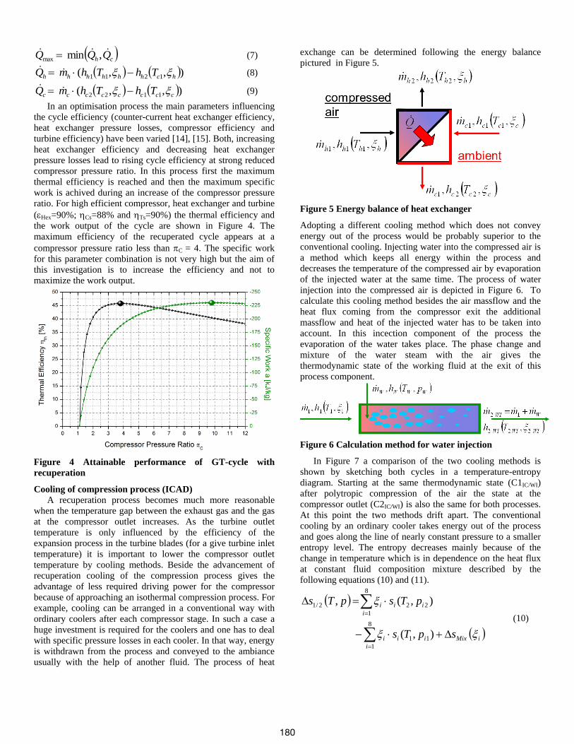
In an optimisation process the main parameters influencing
the cycle efficiency (counter-current heat exchanger efficiency,
heat exchanger pressure losses, compressor efficiency and
turbine efficiency) have been varied [14], [15]. Both, increasing
heat exchanger efficiency and decreasing heat exchanger
pressure losses lead to rising cycle efficiency at strong reduced
compressor pressure ratio. In this process first the maximum
thermal efficiency is reached and then the maximum specific
work is achived during an increase of the compressor pressure
ratio. For high efficient compressor, heat exchanger and turbine
(Hex=90%; Cs=88% and Ts=90%) the thermal efficiency and
the work output of the cycle are shown in Figure 4. The
maximum efficiency of the recuperated cycle appears at a
compressor pressure ratio less than C = 4. The specific work
for this parameter combination is not very high but the aim of
this investigation is to increase the efficiency and not to
maximize the work output.
Figure 4 Attainable performance of GT-cycle with
recuperation
Cooling of compression process (ICAD)
A recuperation process becomes much more reasonable
when the temperature gap between the exhaust gas and the gas
at the compressor outlet increases. As the turbine outlet
temperature is only influenced by the efficiency of the
expansion process in the turbine blades (for a give turbine inlet
temperature) it is important to lower the compressor outlet
temperature by cooling methods. Beside the advancement of
recuperation cooling of the compression process gives the
advantage of less required driving power for the compressor
because of approaching an isothermal compression process. For
example, cooling can be arranged in a conventional way with
ordinary coolers after each compressor stage. In such a case a
huge investment is required for the coolers and one has to deal
with specific pressure losses in each cooler. In that way, energy
is withdrawn from the process and conveyed to the ambiance
usually with the help of another fluid. The process of heat
exchange can be determined following the energy balance
pictured in Figure 5.
Figure 5 Energy balance of heat exchanger
Adopting a different cooling method which does not convey
energy out of the process would be probably superior to the
conventional cooling. Injecting water into the compressed air is
a method which keeps all energy within the process and
decreases the temperature of the compressed air by evaporation
of the injected water at the same time. The process of water
injection into the compressed air is depicted in Figure 6. To
calculate this cooling method besides the air massflow and the
heat flux coming from the compressor exit the additional
massflow and heat of the injected water has to be taken into
account. In this incection component of the process the
evaporation of the water takes place. The phase change and
mixture of the water steam with the air gives the
thermodynamic state of the working fluid at the exit of this
process component.
Figure 6 Calculation method for water injection
In Figure 7 a comparison of the two cooling methods is
shown by sketching both cycles in a temperature-entropy
diagram. Starting at the same thermodynamic state (C1IC/WI)
after polytropic compression of the air the state at the
compressor outlet (C2IC/WI) is also the same for both processes.
At this point the two methods drift apart. The conventional
cooling by an ordinary cooler takes energy out of the process
and goes along the line of nearly constant pressure to a smaller
entropy level. The entropy decreases mainly because of the
change in temperature which is in dependence on the heat flux
at constant fluid composition mixture described by the
following equations (10) and (11).
iMix
i
iii
i
iii
spTs
pTspTs
8
1
11
8
1
222/1
),(
),(,
(10)
180
0ln8
1
i
i
Mix
i
iiiMixM
MRs (11)
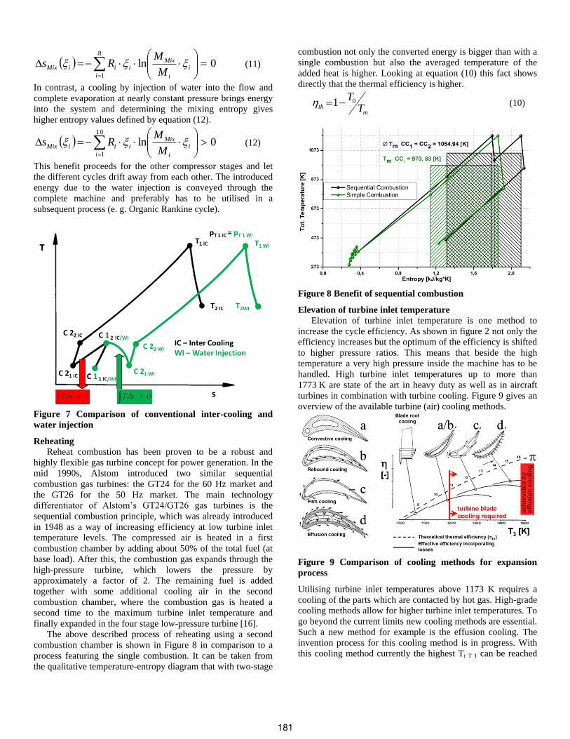
In contrast, a cooling by injection of water into the flow and
complete evaporation at nearly constant pressure brings energy
into the system and determining the mixing entropy gives
higher entropy values defined by equation (12).
0ln10
1
i
i
Mix
i
iiiMixM
MRs (12)
This benefit proceeds for the other compressor stages and let
the different cycles drift away from each other. The introduced
energy due to the water injection is conveyed through the
complete machine and preferably has to be utilised in a
subsequent process (e. g. Organic Rankine cycle).
Figure 7 Comparison of conventional inter-cooling and
water injection
Reheating
Reheat combustion has been proven to be a robust and
highly flexible gas turbine concept for power generation. In the
mid 1990s, Alstom introduced two similar sequential
combustion gas turbines: the GT24 for the 60 Hz market and
the GT26 for the 50 Hz market. The main technology
differentiator of Alstom’s GT24/GT26 gas turbines is the
sequential combustion principle, which was already introduced
in 1948 as a way of increasing efficiency at low turbine inlet
temperature levels. The compressed air is heated in a first
combustion chamber by adding about 50% of the total fuel (at
base load). After this, the combustion gas expands through the
high-pressure turbine, which lowers the pressure by
approximately a factor of 2. The remaining fuel is added
together with some additional cooling air in the second
combustion chamber, where the combustion gas is heated a
second time to the maximum turbine inlet temperature and
finally expanded in the four stage low-pressure turbine [16].
The above described process of reheating using a second
combustion chamber is shown in Figure 8 in comparison to a
process featuring the single combustion. It can be taken from
the qualitative temperature-entropy diagram that with two-stage
combustion not only the converted energy is bigger than with a
single combustion but also the averaged temperature of the
added heat is higher. Looking at equation (10) this fact shows
directly that the thermal efficiency is higher.
mth T
T01 (10)
Figure 8 Benefit of sequential combustion
Elevation of turbine inlet temperature
Elevation of turbine inlet temperature is one method to
increase the cycle efficiency. As shown in figure 2 not only the
efficiency increases but the optimum of the efficiency is shifted
to higher pressure ratios. This means that beside the high
temperature a very high pressure inside the machine has to be
handled. High turbine inlet temperatures up to more than
1773 K are state of the art in heavy duty as well as in aircraft
turbines in combination with turbine cooling. Figure 9 gives an
overview of the available turbine (air) cooling methods.
Figure 9 Comparison of cooling methods for expansion
process
Utilising turbine inlet temperatures above 1173 K requires a
cooling of the parts which are contacted by hot gas. High-grade
cooling methods allow for higher turbine inlet temperatures. To
go beyond the current limits new cooling methods are essential.
Such a new method for example is the effusion cooling. The
invention process for this cooling method is in progress. With
this cooling method currently the highest Tt T 1 can be reached
181
because the flux of cooling air can be adapted exactly to the
requirements [17], [18].
Turbine blade air cooling postulates an amount of air which
is not guided to the combustion chamber and therefore does not
participate at the energy input provided by the fuel. This
fraction of air absorbs the required compressor work but is not
energised by the fuel and therefore cannot perform the same
work as the energised fluid does. In this way the gain of
efficiency due to increased turbine inlet temperature has to be
regarded in contrast to the energy deficit due to the use of not
energised fluid. Within a certain limit of turbine inlet
temperature, the benefit for the cycle is higher than the effort
for turbine cooling. For this range of turbine inlet temperatures
an increasing efficiency of the cycle can be observed and
elevation of turbine inlet temperature is a reasonable method to
increase the cycle efficiency.
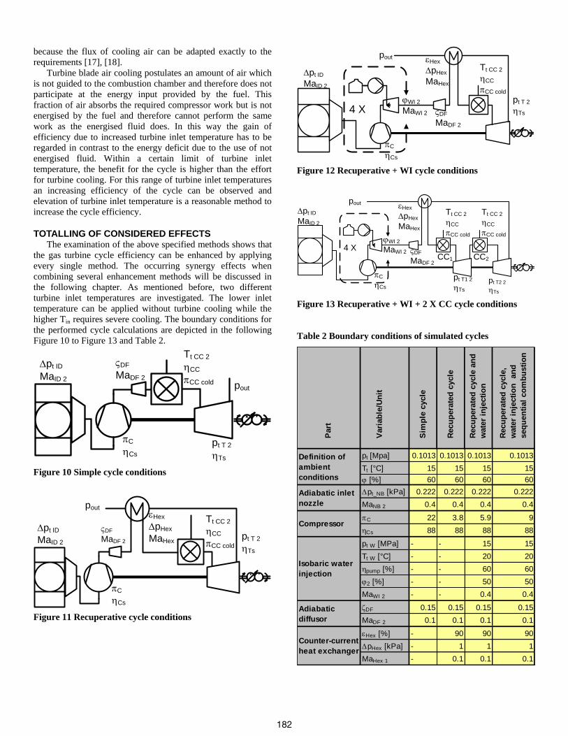
TOTALLING OF CONSIDERED EFFECTS The examination of the above specified methods shows that
the gas turbine cycle efficiency can be enhanced by applying
every single method. The occurring synergy effects when
combining several enhancement methods will be discussed in
the following chapter. As mentioned before, two different
turbine inlet temperatures are investigated. The lower inlet
temperature can be applied without turbine cooling while the
higher Tin requires severe cooling. The boundary conditions for
the performed cycle calculations are depicted in the following
Figure 10 to Figure 13 and Table 2.
pt ID
MaID 2
C
Cs
VDF
MaDF 2
Tt CC 2
CC
CC cold
pt T 2
Ts
pout
Figure 10 Simple cycle conditions
P-39
pt ID
MaID 2
C
Cs
VDF
MaDF 2
Tt CC 2
CC
CC cold
pt T 2
Ts
pout
Hex
pHex
MaHex
Figure 11 Recuperative cycle conditions
4 X
pt ID
MaID 2
C
Cs
VDF
MaDF 2
Tt CC 2
CC
CC cold
pt T 2
Ts
pout Hex
pHex
MaHex
WI 2
MaWI 2
Figure 12 Recuperative + WI cycle conditions
CC1
4 X CC2
pt ID
MaID 2
C
Cs
VDF
MaDF 2
Tt CC 2
CC
CC cold
pt T2 2
Ts
pout Hex
pHex
MaHex
pt T1 2
Ts
Tt CC 2
CC
CC coldWI 2
MaWI 2
Figure 13 Recuperative + WI + 2 X CC cycle conditions
Table 2 Boundary conditions of simulated cycles P
art
Vari
ab
le/U
nit
Sim
ple
cycle
Recu
pera
ted
cycle
Recu
pera
ted
cycle
an
d
wate
r in
jecti
on
Recu
pera
ted
cycle
,
wate
r in
jecti
on
an
d
seq
uen
tial
co
mb
usti
on
pt [Mpa] 0.1013 0.1013 0.1013 0.1013
Tt [°C] 15 15 15 15
[%] 60 60 60 60
pt_NB [kPa] 0.222 0.222 0.222 0.222
MaNB 2 0.4 0.4 0.4 0.4
C 22 3.8 5.9 9
Cs 88 88 88 88
pt W [MPa] - - 15 15
Tt W [°C] - - 20 20
pump [%] - - 60 60
2 [%] - - 50 50
MaWI 2 - - 0.4 0.4
DF 0.15 0.15 0.15 0.15
MaDF 2 0.1 0.1 0.1 0.1
Hex [%] - 90 90 90
pHex [kPa] - 1 1 1
MaHex 1 - 0.1 0.1 0.1
Definition of
ambient
conditions
Adiabatic inlet
nozzle
Compressor
Isobaric water
injection
Adiabatic
diffusor
Counter-current
heat exchanger
182
FS
CC [%] 99.8 99.8 99.8 99.8
CC cold 0.98 0.98 0.98 0.98
Tt CC 2 [°C] 900 900 900 900
pt T 2 [MPa] 0.1013 0.1023 0.1023 0.4887
pt T2 2 [MPa] - - - 0.1023
Ts [%] 90 90 90 90
Mechanical
efficiencymech [%] 100 100 100 100
Natural gas Thyssengas GmbH
(October 2009) [19]
Turbine
Combustion
chamber
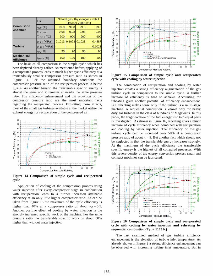
The basis of all comparison is the simple cycle which has
been depicted already earlier. As mentioned before, applying of
a recuperated process leads to much higher cycle efficiency at a
tremendously smaller compressor pressure ratio as shown in
Figure 14. For the assumed boundary conditions the
compressor pressure ratio of the recuperated process is below
c= 4. As another benefit, the transferable specific energy is
almost the same and it remains at nearly the same pressure
ratio. The efficiency enhancement and the reduction of the
compressor pressure ratio are the most important facts
regarding the recuperated process. Exploiting these effects,
most of the small gas turbines available at the market utilise the
exhaust energy for recuperation of the compressed air.
Figure 14 Comparison of simple cycle and recuperated
cycle
Application of cooling of the compression process using
water injection after every compressor stage in combination
with recuperation leads to a further increased attainable
efficiency at an only little higher compressor ratio. As can be
taken from Figure 15 the maximum of the cycle efficiency is
higher than 40% at a compressor ratio of about C= 6.5.
Another positive effect of cooling by water injection is the
strongly increased specific work of the machine. For the same
pressure ratio the transferable specific work is about 50%
higher than without water injection.
Figure 15 Comparison of simple cycle and recuperated
cycle with cooling by water injection
The combination of recuperation and cooling by water
injection creates a strong efficiency augmentation of the gas
turbine cycle in comparison to the simple cycle. A further
increase of efficiency is hard to achieve. Accounting for
reheating gives another potential of efficiency enhancement.
But reheating makes sense only if the turbine is a multi-stage
machine. A sequential combustion is known only for heavy
duty gas turbines in the class of hundreds of Megawatts. In this
paper, the fragmentation of the fuel energy into two equal parts
is investigated. As shown in Figure 16, reheating gives a minor
increase of cycle efficiency when combined with recuperation
and cooling by water injection. The efficiency of the gas
turbine cycle can be increased over 50% at a compressor
pressure ratio of about = 9. But another fact which should not
be neglected is that the transferable energy increases strongly.
At the maximum of the cycle efficiency the transferable
specific energy is the highest of all compared processes. With
this severe density of the energy conversion process small and
compact machines can be fabricated.
Figure 16 Comparison of simple cycle and recuperated
cycle with cooling by water injection and reheating by
sequential combustion (TT1 = 1173 K)
The last examined method of gas turbine efficiency
enhancement is the elevation of turbine inlet temperature. As
already shown in Figure 2 a strong efficiency enhancement can
be observed with increasing turbine inlet temperature. But in
183
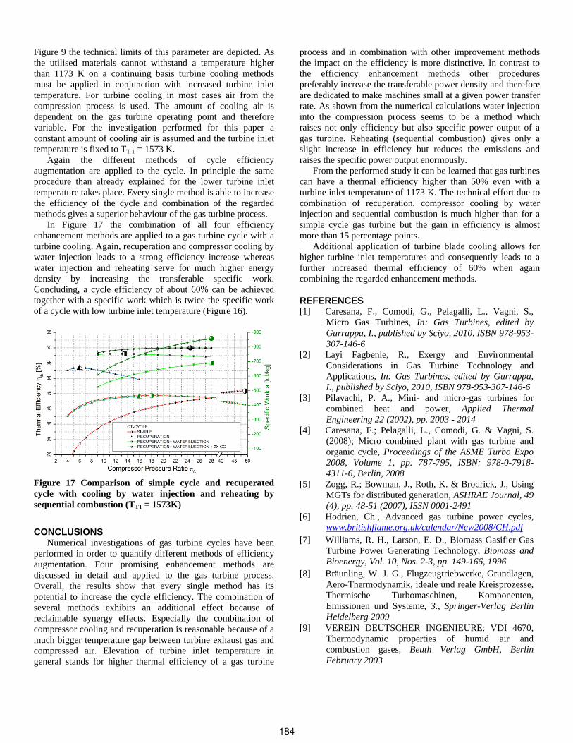
Figure 9 the technical limits of this parameter are depicted. As
the utilised materials cannot withstand a temperature higher
than 1173 K on a continuing basis turbine cooling methods
must be applied in conjunction with increased turbine inlet
temperature. For turbine cooling in most cases air from the
compression process is used. The amount of cooling air is
dependent on the gas turbine operating point and therefore
variable. For the investigation performed for this paper a
constant amount of cooling air is assumed and the turbine inlet
temperature is fixed to TT 1 = 1573 K.
Again the different methods of cycle efficiency
augmentation are applied to the cycle. In principle the same
procedure than already explained for the lower turbine inlet
temperature takes place. Every single method is able to increase
the efficiency of the cycle and combination of the regarded
methods gives a superior behaviour of the gas turbine process.
In Figure 17 the combination of all four efficiency
enhancement methods are applied to a gas turbine cycle with a
turbine cooling. Again, recuperation and compressor cooling by
water injection leads to a strong efficiency increase whereas
water injection and reheating serve for much higher energy
density by increasing the transferable specific work.
Concluding, a cycle efficiency of about 60% can be achieved
together with a specific work which is twice the specific work
of a cycle with low turbine inlet temperature (Figure 16).
Figure 17 Comparison of simple cycle and recuperated
cycle with cooling by water injection and reheating by
sequential combustion (TT1 = 1573K)
CONCLUSIONS Numerical investigations of gas turbine cycles have been
performed in order to quantify different methods of efficiency
augmentation. Four promising enhancement methods are
discussed in detail and applied to the gas turbine process.
Overall, the results show that every single method has its
potential to increase the cycle efficiency. The combination of
several methods exhibits an additional effect because of
reclaimable synergy effects. Especially the combination of
compressor cooling and recuperation is reasonable because of a
much bigger temperature gap between turbine exhaust gas and
compressed air. Elevation of turbine inlet temperature in
general stands for higher thermal efficiency of a gas turbine
process and in combination with other improvement methods
the impact on the efficiency is more distinctive. In contrast to
the efficiency enhancement methods other procedures
preferably increase the transferable power density and therefore
are dedicated to make machines small at a given power transfer
rate. As shown from the numerical calculations water injection
into the compression process seems to be a method which
raises not only efficiency but also specific power output of a
gas turbine. Reheating (sequential combustion) gives only a
slight increase in efficiency but reduces the emissions and
raises the specific power output enormously.
From the performed study it can be learned that gas turbines
can have a thermal efficiency higher than 50% even with a
turbine inlet temperature of 1173 K. The technical effort due to
combination of recuperation, compressor cooling by water
injection and sequential combustion is much higher than for a
simple cycle gas turbine but the gain in efficiency is almost
more than 15 percentage points.
Additional application of turbine blade cooling allows for
higher turbine inlet temperatures and consequently leads to a
further increased thermal efficiency of 60% when again
combining the regarded enhancement methods.
REFERENCES [1] Caresana, F., Comodi, G., Pelagalli, L., Vagni, S.,
Micro Gas Turbines, In: Gas Turbines, edited by
Gurrappa, I., published by Sciyo, 2010, ISBN 978-953-
307-146-6 [2] Layi Fagbenle, R., Exergy and Environmental
Considerations in Gas Turbine Technology and
Applications, In: Gas Turbines, edited by Gurrappa,
I., published by Sciyo, 2010, ISBN 978-953-307-146-6
[3] Pilavachi, P. A., Mini- and micro-gas turbines for
combined heat and power, Applied Thermal
Engineering 22 (2002), pp. 2003 - 2014
[4] Caresana, F.; Pelagalli, L., Comodi, G. & Vagni, S.
(2008); Micro combined plant with gas turbine and
organic cycle, Proceedings of the ASME Turbo Expo
2008, Volume 1, pp. 787-795, ISBN: 978-0-7918-
4311-6, Berlin, 2008
[5] Zogg, R.; Bowman, J., Roth, K. & Brodrick, J., Using
MGTs for distributed generation, ASHRAE Journal, 49
(4), pp. 48-51 (2007), ISSN 0001-2491
[6] Hodrien, Ch., Advanced gas turbine power cycles,
www.britishflame.org.uk/calendar/New2008/CH.pdf
[7] Williams, R. H., Larson, E. D., Biomass Gasifier Gas
Turbine Power Generating Technology, Biomass and
Bioenergy, Vol. 10, Nos. 2-3, pp. 149-166, 1996
[8] Bräunling, W. J. G., Flugzeugtriebwerke, Grundlagen,
Aero-Thermodynamik, ideale und reale Kreisprozesse,
Thermische Turbomaschinen, Komponenten,
Emissionen und Systeme, 3., Springer-Verlag Berlin
Heidelberg 2009
[9] VEREIN DEUTSCHER INGENIEURE: VDI 4670,
Thermodynamic properties of humid air and
combustion gases, Beuth Verlag GmbH, Berlin
February 2003
184
[10] The international Association for the Properties of
Water and Steam: Revised Release on the IAPWS
Industrial Formulation 1997 for the Thermodynamic
Properties of Water and Steam, Lucerne, Switzerland
August 2007, http://www.iapws.org/relguide/IF97-
Rev.pdf
[11] Hermann, S., Kretzschmar, H.-J., Teske, V., Vogel, E.,
Ulbig, P., Span, R., Gatley, D. P.,: Determination of
Thermodynamic and Transport Properties of Humid
Air for Power Cycle Calculations, Braunschweig 2009,
ISBN 978-3-86509-917-4, http://thermodynamik.hs-
zigr.de/cmsfg/_data/PTB_Bericht_Bremerhaven_2009.
pdf]
[12] Lemmon, E. W.; Jacobsen, R. T.; Penoncello, S. G.;
Friend, D. G.: Thermodynamic Properties of Air and
Mixtures of Nitrogen, Argon and Oxygen from 60 to
2000 K at Pressures to 2000 MPa., J. Phys. Chem. Ref.
Data 29 (2000) Nr. 2, S. 331-385,
http://www.nist.gov/data/PDFfiles/jpcrd581.pdf
[13] Kretzschmar, H.-J., Stöcker, I., University
Zittau/Görlitz, Chair for Technical Thermodynamics,
http://thermodynamik.hs-
zigr.de/cmsfg/Stoffwertbibliothek/index.php?rubric=St
offwertbibliothek
[14] Kim, T. S., Hwang, S. H., Part load performance
analysis of recuperated gas turbines considering engine
configuration and operation strategy, Energy, Volume
31, Issues 2-3, 2006, pp. 260-277
[15] Stevens, T., Verplaetsen F., Baelmans M.,
Requirements for Recuperators in Micro Gas Turbines,
The Fourth International Workshop on Micro and
Nanotechnology for Power Generation and Energy
Conversion Applications, PowerMEMS 2004, Kyoto
Japan, 2004
[16] Güthe, F., Hellat, J., Flohr, P., The Reheat Concept:
The Proven Pathway to Ultralow Emissions and High
Efficiency and Flexibility, Journal of Engineering for
Gas Turbines and Power, MARCH 2009, Vol. 131 /
021503-1
[17] Poprawe, P., Kelbassa, I., Walther, K., Witty, M.,
Bohn, D., Krewinkel, R., Optimising and
Manufacturing a Laser-Drilled Cooling Hole
Geometry for Effusion Cooled Multi-Layer Plates,
ISROMAC-12, February 2008, Hawaii, ISROMAC12-
2008-20091
[18] Bohn, D., Improved Cooling Concept for Turbine
Blades of High-Temperature Gas Turbines,
VGB PowerTech 12/2007 pp.96-103
[19] Product informationen of Thyssengas Erdgaslogistik:
Fuel analysis month October 2009
185