ach 500 series adjustable frequency ac drives
TRANSCRIPT
ACH 500 SeriesAdjustable Frequency AC Drives
Product Bulletin Effective 7/1/95ACH500-02C Supersedes 10/1/93
1
Product BulletinACH500-02C
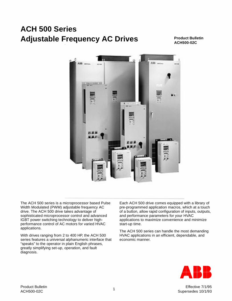
The ACH 500 series is a microprocessor based Pulse Width Modulated (PWM) adjustable frequency AC drive. The ACH 500 drive takes advantage of sophisticated microprocessor control and advanced IGBT power switching technology to deliver high-performance control of AC motors for varied HVAC applications.
With drives ranging from 2 to 400 HP, the ACH 500 series features a universal alphanumeric interface that “speaks” to the operator in plain English phrases, greatly simplifying set-up, operation, and fault diagnosis.
Each ACH 500 drive comes equipped with a library of pre-programmed application macros, which at a touch of a button, allow rapid configuration of inputs, outputs, and performance parameters for your HVAC applications to maximize convenience and minimize start-up time.
The ACH 500 series can handle the most demanding HVAC applications in an efficient, dependable, and economic manner.
ACH 500HVAC AC DRIVES
2
FEATURES
STANDARD FEATURES UL Listed CSA Approved 40 Character Multi-lingual Alphanumeric Display
For:• Output Frequency• Speed (RPM, %, or user programmable)• Motor Current• Calculated Motor Torque• Calculated Motor Power• DC Bus Voltage• Output Voltage• Heatsink Temperature (°F & °C)• Elapsed Time Meter• kWh Meter• Parameter Data• Fault Text• Warning Text• Supervision Text
RS-485 Communications Serial Modbus Protocol Two (2) Analog Inputs Six (6) Programmable Digital Inputs Two (2) Programmable Analog Outputs Three (3) Programmable Form C Relay Outputs Adjustable Filters On Analog Inputs and Outputs Input Speed Signals
Current 0(4)-20 mAVoltage 0(2)-10 VDCIncrease/Decrease Speed ContactsRS-485 Communications
Start/Stop2 Wire (Dry Contact Closure)3 Wire (Momentary Dry Contacts)Application Of Input Power
All Control Inputs Isolated From Ground and Power Protection Circuits
Over CurrentGround FaultOver VoltageUnder VoltageOver TemperatureAdaptable Electronic Motor Overload (I2t)
Input Line Fuses Stall Protection Underload Function Three (3) Current Limit Circuits Electronic Reverse Rapid Reverse DC Injection Braking DC Hold Auto Restart-Customer Selectable and Adjustable Two (2) Independently Adjustable Accel and Decel
Ramps Linear Or three (3) “S” Curve Accel/Decel Ramps
Ramp Or Coast To A Stop Programmable Maximum Frequency To 500 Hz
(ACH 501) Integral Programmable PI Setpoint Controller Mathematical Functions on Analog Signals Seven (7) Preset Speeds Five (5) Critical Frequency Lockout Bands V/Hz Shape
LinearSquaredAutomatic
Start FunctionsRampFlying StartAutomatic Torque Boost
Automatic Slip Compensation (selectable) IR Compensation - Manual or Automatic Automatic Extended Power Loss Ride Through
(selectable) DC Line Reactor
OPTIONAL FEATURES Disconnect Switch Circuit Breaker Manual Bypass Automatic Bypass Service Switch Motor Overload Relay 115 VAC Control Interface AC Line Reactors Intelligent Remote Keypad/Display Panel Pressure (3-15 psi) to Electric Transducer Digital Input Isolators LonWorks Interface Direct N2 Bus™ connection to Johnson Control
Metasys™ system DMT 500PC DOS based Drive Monitoring Tool
software DPT 500 Windows based Drive Programming Tool
software
ACH 500HVAC AC DRIVES
3
SPECIFICATIONS
Input Connection Voltage (VIN)....................................................................... 480 volt units - 3 phase, 440/460/480/500 +/-10% permitted tolerance
................................................................................ 230 volt units - 3 phase, 208/220/230/240 +/-10% permitted tolerance Frequency .......................................................................... 48... 63 Hz Power factor: For fundamental ........................................... ~ 0.98
Motor Connection Output voltage: ................................................................... 3φ 0 to VIN (Vmax at field weakening point) Output frequency: ............................................................... 0 to 500 Hz (ACH 501), 0 to 120 Hz (ACH 502) Frequency resolution:......................................................... 0.01 Hz Digital, 0 to 120 Hz; 0.1 Hz >120 Hz
................................................................................ 12 BIT - analog input 2
................................................................................ 10 BIT - analog input 1 Switching frequency fs ....................................................... 1.0 to 12.0 kHz (ACH 501) factory set at 3kHz
................................................................................ 3.0 kHz (ACH 502) Continuous output current:
Variable torque: ....................................................... Rated IRSQ (Rated current, Variable Torque) Overload Capacity:
Variable torque: ....................................................... 1.1 x IRSQ, for 1 min every 10 min Starting duty: ...................................................................... Approx. 1.4 x IRSQ for 2 sec every 15 sec Field weakening point:........................................................ 30 to 500 Hz (ACH 501), 30 to 180 Hz (ACH 502) Acceleration time: ............................................................... 0.1 to 1800 sec. Deceleration time: .............................................................. 0.1 to 1800 sec. Enclosure: .......................................................................... NEMA 12, NEMA 1, chassis Environmental limits:
Ambient operating temperature (fs=3 kHz) ............. 32 to 104°F (0 to 40° C) NEMA 1 & NEMA 12Storage temperature: .............................................. -40 to +158°F (-40 to +70°C)Cooling method:...................................................... Integral fan(s)Relative humidity:.................................................... max 95%, no condensation allowedAltitude: max ........................................................... 3300 ft. (1000 m) above sea level (100% load)................................................................................ 1% derating every 330 ft. above 3300 ft.
Agency Approval ................................................................ UL, CSA Approved
External Control Connections Two programmable Analog Inputs:
Voltage reference:................................................... 0 to 10 V, 200k ohm single endedCurrent reference:................................................... 0 to 20 mA, 250 ohms single endedPotentiometer.......................................................... 10 VDC, 10 mA (1K to 10K ohms)
Auxiliary voltage: ................................................................ +24 VDC, max 200 mA Six Programmable Digital Inputs ........................................ 24 VDC Two Programmable Analog Outputs:.................................. 0 (4) to 20 mA, 500 ohm maximum load Three Programmable Relay (Form C) Outputs:
Max switching voltage ............................................. 300 VDC/250 VACMax switching current ............................................. 8 A/24 VDC, 0.4 A/250 VDCMax switching power............................................... 2000 VA/250 VACMax continuous current........................................... 2A
Protections:Overcurrent trip limit:............................................... 315% instantaneous, 225% (RMS)Slow current regulation limit: ................................... 125% (RMS) max.Rapid current regulation limit: ................................. 170% (RMS) max.Current switch-off limit:............................................ 255% instantaneous, 175% (RMS) ACH 501................................................................................ 315% instantaneous, 225% (RMS) ACH 502Overvoltage trip limit: .............................................. 130%Undervoltage trip limit: ............................................ 65%Overtemperature (heatsink): ................................... +158°F (+70°C) ACH 501, +185°F (+85°C) ACH 502Auxiliary voltage: ..................................................... Short Circuit ProtectedGround fault: ........................................................... ProtectedMicroprocessor fault:............................................... ProtectedMotor stall protection............................................... ProtectedMotor overtemperature protection (I2t).................... ProtectedAC Line Fuses ........................................................ Standard
Specifications are subject to change without notice. Consult factory when specifications are critical.
ACH 500HVAC AC DRIVES
4
DRIVE FEATURES - OPERATOR INTERFACE
2-Line, 40-Character, Multilingual Alphanumeric Display
Highly legible liquid crystal display (LCD) can access more than 120 parameter names, 330 values (including energy consumption and elapsed time), plus an array of fault and warning messages. The ACH 500 presents this information in “plain” English (no codes) (or 8 other user-selected languages, including: French, Spanish, German, Italian, Swedish, Finnish, Danish and Dutch).
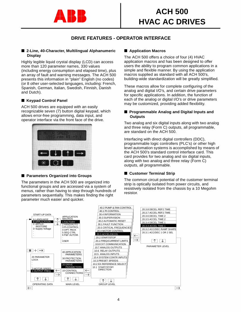
Keypad Control Panel
ACH 500 drives are equipped with an easily recognizable seven (7) button digital keypad, which allows error-free programming, data input, and operator interface via the front face of the drive.
Parameters Organized into Groups
The parameters in the ACH 500 are organized into functional groups and are accessed via a system of menus, rather than having to step through hundreds of parameters sequentially. This makes finding the right parameter much easier and quicker.
keypad photo
40.2 PUMP & FAN CONTROL40.1 PI-CONTROL30.4 INFORMATION30.3 SUPERVISION30.2 AUTOMATIC RESET30.1 FAULT FUNCTION20.5 CRITICAL FREQUENCIES20.4 MOTOR CONTROL20.3 ACCEL/DECEL
20.2 START/STOP20.1 FREQ/CURRENT LIMITS10.8 EXT COMMUNICATION10.7 ANALOG OUTPUTS10.6 RELAY OUTPUTS10.5 ANALOG INPUTS
START-UP DATA
C APPLIC. RESTORED Supply Voltage
20 PARAMETER ....
30 PROTECTION PARAMETERS
10 CONTROL CONNECTIONS
10.4 SYSTEM CONTR INPUTS10.3 PRESET SPEEDS10.2 EX REFERENCE SELECT10.1 START/STOP/ DIRECTION
20.3.8 DECEL REF2 TIME20.3.7 ACCEL REF2 TIME20.3.6 DECEL TIME 220.3.5 ACCEL TIME 220.3.4 DECEL TIME 120.3.3 ACCEL TIME 120.3.2 ACC/DEC RAMP SHAPE20.3.1 ACC/DEC 1 OR 2 SEL
OPERATING DATA MAIN LEVEL GROUP LEVEL
PARAMETER LEVEL
1 OUTPUT FREQ.2 MOTOR SPEED
PARAMETERS20 DRIVE
A LANGUAGEAPPLICATION
1 FACTORYMACROS
2 HAND/AUTO3 PI-CONTROL4 OPT. PACK5 SEQ CTRL
B APPLICATION
.
.
. 6 P&F AUTOM...USER
40 APPLICATION PARAMETERS
LOCK
Application Macros
The ACH 500 offers a choice of four (4) HVAC application macros and has been designed to offer users the ability to program common applications in a simple and flexible manner. By using the application macros supplied as standard with all ACH 500’s, building-wide standardization will be greatly simplified.
These macros allow for complete configuring of the analog and digital I/O’s, and certain drive parameters for specific applications. In addition, the function of each of the analog or digital I/O’s or drive parameters may be customized, providing added flexibility.
Programmable Analog and Digital Inputs and Outputs
Two analog and six digital inputs along with two analog and three relay (Form C) outputs, all programmable, are standard on the ACH 500.
Interfacing with direct digital controllers (DDC), programmable logic controllers (PLC’s) or other high level automation systems is accomplished by means of the ACH 500’s standard control interface card. This card provides for two analog and six digital inputs, along with two analog and three relay (Form C) outputs, all programmable.
Customer Terminal Strip
The common circuit potential of the customer terminal strip is optically isolated from power circuits, and resistively isolated from the chassis by a 10 Megohm resistor.

ACH 500HVAC AC DRIVES
5
DRIVE FEATURES - OPERATOR INTERFACE (cont’d)
Serial Communication
RS-485 serial communications port to support a Remote Panel, as well as PC and PLC for monitoring and control is standard on the ACH 500.
The ACH 500 drive supports three different protocols, without any additional circuit boards:
• Serial Modbus RTU, an industry standard master/slave protocol which will allow up to 31 drives to be controlled from a PC, PLC, DCS, or other automation system.
• Johnson Controls N2 Bus connection. This uses the serial port standard on ACH 500 drives. There is no need for any additional hardware. Existing drives are easily retrofitted for N2 Bus with a simple EPROM change.
• GS Panel protocol to support the optional remote panel listed to the right.
More information is available on serial communications options for the ACH 500. Ask your local ABB representative.
Modbus and GS Panel protocols are standard on every drive.
N2 Bus is a field installable firmware update.
READ WRITE
HOLDSTATUS
DRIVE
SHIFT REF ALL NET INI
ABB Drives
REMOTE PANEL
AAAAAA
ABB Drives ACH 500
AAAAAAAAAAAAAAAAAAAAAAAAAAAAAAAA
AAAAAAAAAAAAAAAAAAA
AAAAAA
Remote Panel (Optional)
The Remote Panel is a Keypad/Display that provides the the same alpha-numeric display and functionality as the standard local panel mounted on the ACS 500. This panel can be mounted at a remote location.
One panel can control up to 31 ACH 500’s. All drive functions that can be performed at the drive keypad can also be performed with the Remote Panel. Speed, Start/Stop, and Direction commands can be broadcast simultaneously to all drives connected. Network initialization (configuration) is also performed by the Remote Panel. Additionally, the Remote Panel can be used to upload all drive parameters and store them in memory. They can then be downloaded to another drive. The remote panel controls the ACH 500 via the RS-485 Serial Communication Link. A 9.8 ft. (3 m) cable is included to connect to the first drive (maximum distance allowable with drive supplied power). Maximum length of the RS-485 cable is 3,937 feet (1200 m) if a separate (9 v ±1 v, 200mA) power supply is provided for the panel.
Hand-Off-Auto Switch & Speed Pot
Cover-mounted switch is prewired at the factory to allow the user to select one of three modes. In HAND, the drive will be started, and the speed will be controlled by the cover-mounted speed potentiometer. In OFF, the drive will be stopped. In AUTO, the drive will be started by a remote contact closure provided by the customer, and the speed will be controlled by a remote signal (voltage, current or pneumatic).
ACH 500HVAC AC DRIVES
6
DRIVE FEATURES - POWER
Three Current Limit Circuits and 225% O.C. Trip
The ACH 500’s current limit circuitry and 225% (315% peak) overcurrent trip level, allows the ACH 500 to operate as a “tripless” drive. The three current limit circuits dynamically control motor current and prevent excessive motor current from unduly tripping the drive. The three current limit functions operate as follows:
1. Rapid Current Regulation.The Rapid Current Regulation is adjustable from 50% to 170%. If the motor current exceeds the Current Limit setting, the ACH 500 will stop, and decrease the output frequency until the motor current is reduced below the current limit level, at which time the output frequency will accelerate (at the rate set by the acceleration time) to the set frequency. The Rapid Current Regulation allows up to 200% current to be drawn for a short period of time before the current is reduced to the Slow Current Regulation Limit.
2. Slow Current Regulation.Adjustable from 50% to 125% of the ACH 500’s rated current, this current regulation circuit operates similarly to the Rapid Current Regulation, except at a slower rate.
3. Current Switch-Off Limit.When the rapid current regulation limit is exceeded, and the Current Switch-Off Limit is reached (255% peak in ACH 501 and 315% peak in ACH 502) the output voltage to the motor is shut off momentarily. Every two to three milliseconds, the output voltage is switched back on to take control of the motor. If the current is not below the 150% level, voltage will again be switched off.
This function will operate 10 times to control the motor current prior to it either controlling the motor, or shutting down the drive on an overcurrent trip.
DC Line Reactor
A DC Line Reactor is standard equipment on the ACH 500. This added impedance to the DC link results in several improvements over Pulse Width Modulated (PWM) drives not so equipped. Displacement power factor is thus improved, and lower harmonic distortion on the power line is achieved without additional line inductors or transformers. For harmonic distortion calculations, please contact the factory.
IGBT Power Electronics
The ACH 500 uses the latest IGBT (Insulated Gate Bi-Polar Transistor) power switching devices. These fast response IGBT’s allow “tripless” operation enabling 100% motor load capability at a motor’s rated load. This minimizes the derating requirements of the motor. In addition, audible motor noise is significantly reduced, which means the ACH 500 can be used in applications where low noise levels are essential. Other significant advantages of this technology are:
• Minimal gate currents are achieved for the control of large motor currents. This minimizes the power of the gate circuits and allows lower power supply requirements; resulting in greater commonality of spare parts.
• The inherently fast switching rates of the ACH 500 result in smoother motor control when compared to switching rates below 1 kHz. In addition, they minimize the derating requirements of the AC motor at nominal speed while assuring reliable and safe shut-downs during fault conditions.
• Minimal switching losses of IGBT’s result in better efficiency and allows for smaller enclosures.
Input Power
One of the more unique features of the ACH 500 is its ability to operate from wide range of input power potentials.
Most U.S. based power systems operate at 480 VAC +10% and many AC drives are rated for only 460 VAC + 10%. This results in a maximum operational voltage from 506 VAC to 528 VAC where the utility is within specifications, but above most drives’ capabilities. The ACH 500’s flexibility allows for operation at 500 VAC + 10% (i.e. 550 VAC maximum). Benefit - ability to operate on high lines without nuisance overvoltage trips.
ACH 500HVAC AC DRIVES
7
DRIVE FEATURES - PROTECTION
Power Line Protection
The ACH 500 has built-in fast acting semi-conductor input fuses as standard inside the standard.
Power line voltage surge protection is provided by means of a Metal Oxide Varistor (M.O.V.) across the DC bus or the AC line. This protects the diodes in the ACH 500’s 3-phase full wave bridge.
Integral Protection Circuits
The ACH 500 was designed to protect the drive and motor from the hazards of continuous service in the most demanding of applications. Built-in protection circuits include the following:
• Overcurrent trip limit - 315% instantaneous• Slow current regulation limit -125% • Rapid current regulation limit-170% adjustable• Current switch-off limit-225% instantaneous• Overvoltage trip limit -130%• Undervoltage trip limit -65%• Over temperature protection - YES• Ground fault protection - YES• Microprocessor protection - YES• Motor stall protection - YES• Smart Motor overload protection (I2t) - YES• Single phasing on input in ACH 502 drives
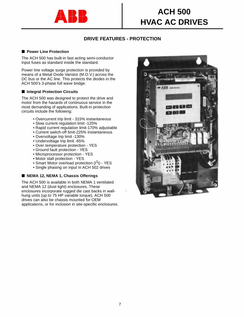
NEMA 12, NEMA 1, Chassis Offerings
The ACH 500 is available in both NEMA 1 ventilated and NEMA 12 (dust tight) enclosures. These enclosures incorporate rugged die cast backs in wall-hung units (up to 75 HP variable torque). ACH 500 drives can also be chassis mounted for OEM applications, or for inclusion in site-specific enclosures.
.
photo of drive without cover
ACH 500HVAC AC DRIVES
8
DRIVE FEATURES - CONTROL
Acceleration/Deceleration Rates
The ACH 500 provides two individually controlled, selectable sets of acceleration/deceleration rates from 0.1 to 1800 seconds.
Min. theoretical time -120 Hz/0.1 seconds
Max. theoretical time - 120 Hz/1800 seconds
Switching between the two accel/decel rates may be controlled via a program designated digital input (Parameter 20.3.1).
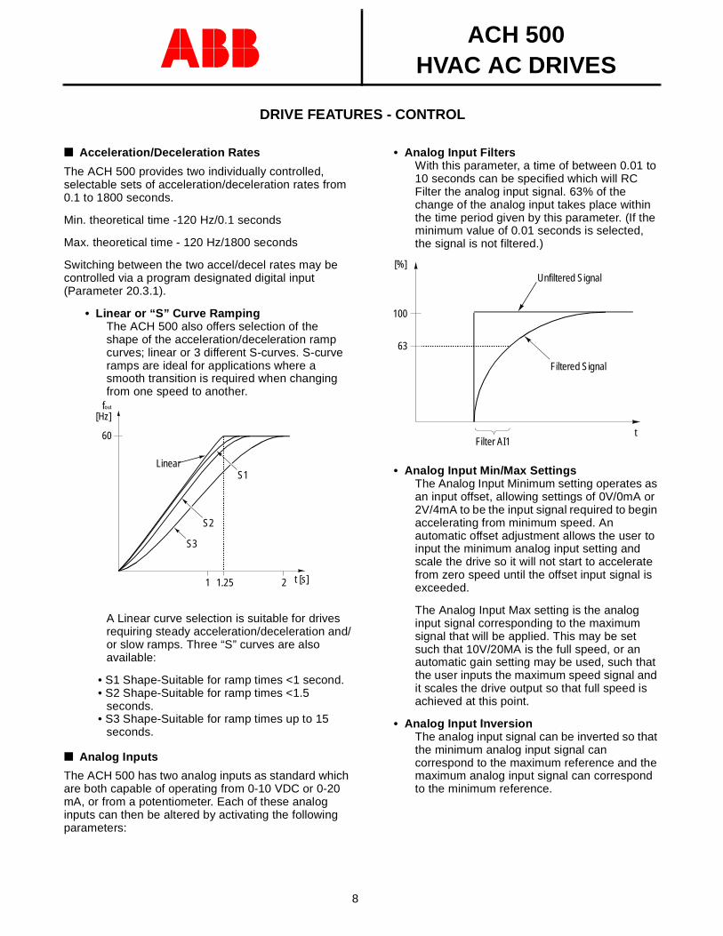
• Linear or “S” Curve Ramping The ACH 500 also offers selection of the shape of the acceleration/deceleration ramp curves; linear or 3 different S-curves. S-curve ramps are ideal for applications where a smooth transition is required when changing from one speed to another.
A Linear curve selection is suitable for drives requiring steady acceleration/deceleration and/or slow ramps. Three “S” curves are also available:
• S1 Shape-Suitable for ramp times <1 second.• S2 Shape-Suitable for ramp times <1.5
seconds.• S3 Shape-Suitable for ramp times up to 15
seconds.
Analog Inputs
The ACH 500 has two analog inputs as standard which are both capable of operating from 0-10 VDC or 0-20 mA, or from a potentiometer. Each of these analog inputs can then be altered by activating the following parameters:
S2
S3
LinearS1
AAAAAAAAAAAAAAAAAAAAAAA60
AAAAAAAAAAAAAAAAAAAAAAAAAAAAAA
[Hz]
1 t [s]
fout
1.25 2
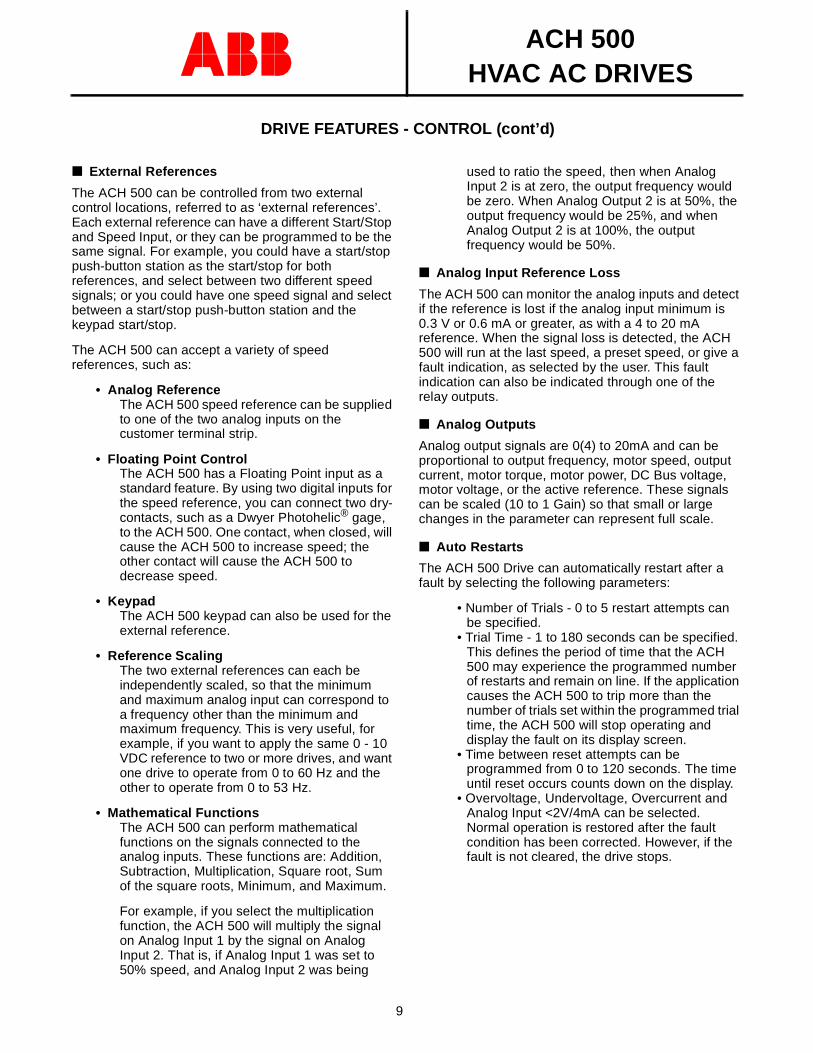
• Analog Input FiltersWith this parameter, a time of between 0.01 to 10 seconds can be specified which will RC Filter the analog input signal. 63% of the change of the analog input takes place within the time period given by this parameter. (If the minimum value of 0.01 seconds is selected, the signal is not filtered.)
• Analog Input Min/Max SettingsThe Analog Input Minimum setting operates as an input offset, allowing settings of 0V/0mA or 2V/4mA to be the input signal required to begin accelerating from minimum speed. An automatic offset adjustment allows the user to input the minimum analog input setting and scale the drive so it will not start to accelerate from zero speed until the offset input signal is exceeded.
The Analog Input Max setting is the analog input signal corresponding to the maximum signal that will be applied. This may be set such that 10V/20MA is the full speed, or an automatic gain setting may be used, such that the user inputs the maximum speed signal and it scales the drive output so that full speed is achieved at this point.
• Analog Input InversionThe analog input signal can be inverted so that the minimum analog input signal can correspond to the maximum reference and the maximum analog input signal can correspond to the minimum reference.
AAAAAAAAAAAAAAAAAAAAA63
AAAAAAAAAAAAAAAAAAAAAAAAAAAAAAAAAAAA
[%]
100
Filter AI1t
Filtered Signal
Unfiltered Signal
ACH 500HVAC AC DRIVES
9
DRIVE FEATURES - CONTROL (cont’d)
External References
The ACH 500 can be controlled from two external control locations, referred to as ‘external references’. Each external reference can have a different Start/Stop and Speed Input, or they can be programmed to be the same signal. For example, you could have a start/stop push-button station as the start/stop for both references, and select between two different speed signals; or you could have one speed signal and select between a start/stop push-button station and the keypad start/stop.
The ACH 500 can accept a variety of speed references, such as:
• Analog ReferenceThe ACH 500 speed reference can be supplied to one of the two analog inputs on the customer terminal strip.
• Floating Point ControlThe ACH 500 has a Floating Point input as a standard feature. By using two digital inputs for the speed reference, you can connect two dry-contacts, such as a Dwyer Photohelic® gage, to the ACH 500. One contact, when closed, will cause the ACH 500 to increase speed; the other contact will cause the ACH 500 to decrease speed.
• KeypadThe ACH 500 keypad can also be used for the external reference.
• Reference ScalingThe two external references can each be independently scaled, so that the minimum and maximum analog input can correspond to a frequency other than the minimum and maximum frequency. This is very useful, for example, if you want to apply the same 0 - 10 VDC reference to two or more drives, and want one drive to operate from 0 to 60 Hz and the other to operate from 0 to 53 Hz.
• Mathematical FunctionsThe ACH 500 can perform mathematical functions on the signals connected to the analog inputs. These functions are: Addition, Subtraction, Multiplication, Square root, Sum of the square roots, Minimum, and Maximum.
For example, if you select the multiplication function, the ACH 500 will multiply the signal on Analog Input 1 by the signal on Analog Input 2. That is, if Analog Input 1 was set to 50% speed, and Analog Input 2 was being
used to ratio the speed, then when Analog Input 2 is at zero, the output frequency would be zero. When Analog Output 2 is at 50%, the output frequency would be 25%, and when Analog Output 2 is at 100%, the output frequency would be 50%.
Analog Input Reference Loss
The ACH 500 can monitor the analog inputs and detect if the reference is lost if the analog input minimum is 0.3 V or 0.6 mA or greater, as with a 4 to 20 mA reference. When the signal loss is detected, the ACH 500 will run at the last speed, a preset speed, or give a fault indication, as selected by the user. This fault indication can also be indicated through one of the relay outputs.
Analog Outputs
Analog output signals are 0(4) to 20mA and can be proportional to output frequency, motor speed, output current, motor torque, motor power, DC Bus voltage, motor voltage, or the active reference. These signals can be scaled (10 to 1 Gain) so that small or large changes in the parameter can represent full scale.
Auto Restarts
The ACH 500 Drive can automatically restart after a fault by selecting the following parameters:
• Number of Trials - 0 to 5 restart attempts can be specified.
• Trial Time - 1 to 180 seconds can be specified. This defines the period of time that the ACH 500 may experience the programmed number of restarts and remain on line. If the application causes the ACH 500 to trip more than the number of trials set within the programmed trial time, the ACH 500 will stop operating and display the fault on its display screen.
• Time between reset attempts can be programmed from 0 to 120 seconds. The time until reset occurs counts down on the display.
• Overvoltage, Undervoltage, Overcurrent and Analog Input <2V/4mA can be selected. Normal operation is restored after the fault condition has been corrected. However, if the fault is not cleared, the drive stops.
ACH 500HVAC AC DRIVES
10
DRIVE FEATURES - CONTROL (cont’d)
Carrier Frequency
By utilizing IGBT’s, the ACH 500 drive employs high switching frequencies, so the motor current is practically sinusoidal. Audible motor noise can also be minimized by choosing a switching frequency up to 12kHz in the ACH 501. These frequencies can be adjusted or changed to best fit the application. When raising the switching frequency above 3 kHz, the switching losses in the drive will increase. Derating may be necessary, depending on the application.
Critical Frequency Lockouts
For applications where it may be necessary to avoid specific frequencies due to mechanical resonance problems in the driven equipment, the ACH 500, with its Critical Frequency Lockout Function, makes it possible to set-up five different frequency ranges which will be avoided during operation of the drive.
Each critical frequency setting allows the user to set low and high critical frequency limits. If the speed reference signal requires the ACH 500 to operate within this critical frequency range, the critical frequency lockout function will keep the ACH 500 operating at the low (or high) limit until the reference is out of the critical frequency range, at which time the output frequency will ramp through the critical frequency range at the set accel or decel ramp.
Extended Power Loss Ride-through
The ACH 500 is equipped with an automatic extended power loss ride-through circuit.
This circuit utilizes the inertia of the load to keep the drive powered. The minimum power loss ride-through is one-cycle (16.6 milliseconds), based on full load and no inertia. However, because inertia of the load generates power to the drive, the ACH 500’s power loss ride-through capability can be extended well beyond one cycle, depending on the load inertia.
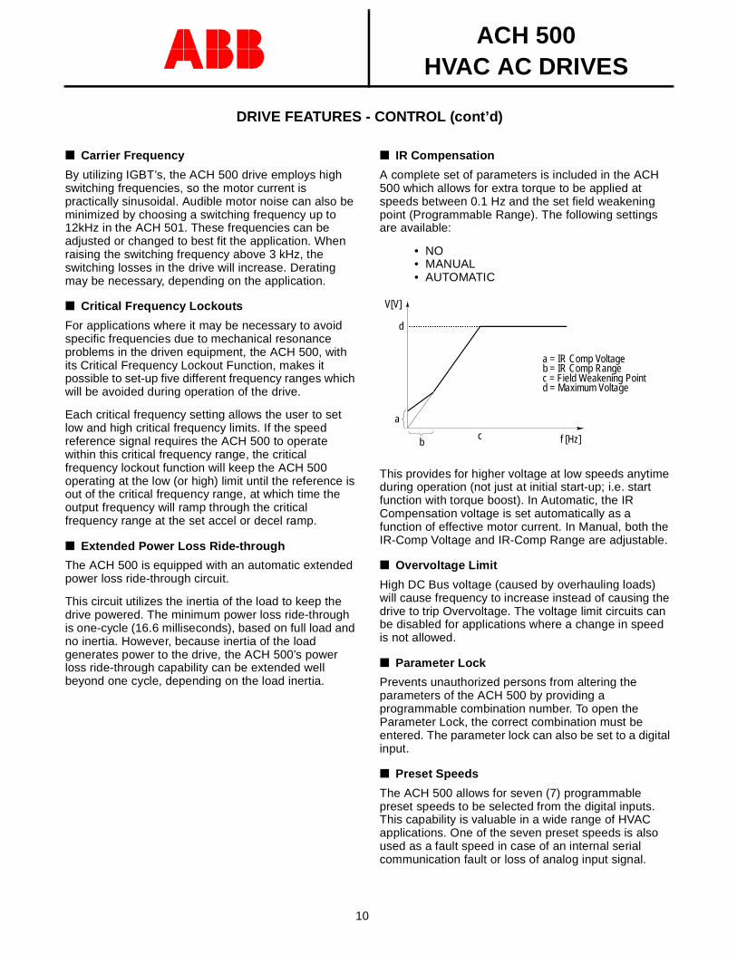
IR Compensation
A complete set of parameters is included in the ACH 500 which allows for extra torque to be applied at speeds between 0.1 Hz and the set field weakening point (Programmable Range). The following settings are available:
• NO• MANUAL• AUTOMATIC
This provides for higher voltage at low speeds anytime during operation (not just at initial start-up; i.e. start function with torque boost). In Automatic, the IR Compensation voltage is set automatically as a function of effective motor current. In Manual, both the IR-Comp Voltage and IR-Comp Range are adjustable.
Overvoltage Limit
High DC Bus voltage (caused by overhauling loads) will cause frequency to increase instead of causing the drive to trip Overvoltage. The voltage limit circuits can be disabled for applications where a change in speed is not allowed.
Parameter Lock
Prevents unauthorized persons from altering the parameters of the ACH 500 by providing a programmable combination number. To open the Parameter Lock, the correct combination must be entered. The parameter lock can also be set to a digital input.
Preset Speeds
The ACH 500 allows for seven (7) programmable preset speeds to be selected from the digital inputs. This capability is valuable in a wide range of HVAC applications. One of the seven preset speeds is also used as a fault speed in case of an internal serial communication fault or loss of analog input signal.
f [Hz]AAAAAAAAAAAAAAAAAAAAAAAAAAAAAAAAAAAAAAAAAAAAAAAAAAAAAAAAAAAAAAd
c
V[V]
AAAAAAAAAAAAAAAAAA
b
a
a = IR Comp Voltageb = IR Comp Rangec = Field Weakening Pointd = Maximum Voltage
ACH 500HVAC AC DRIVES
11
DRIVE FEATURES - CONTROL (cont’d)
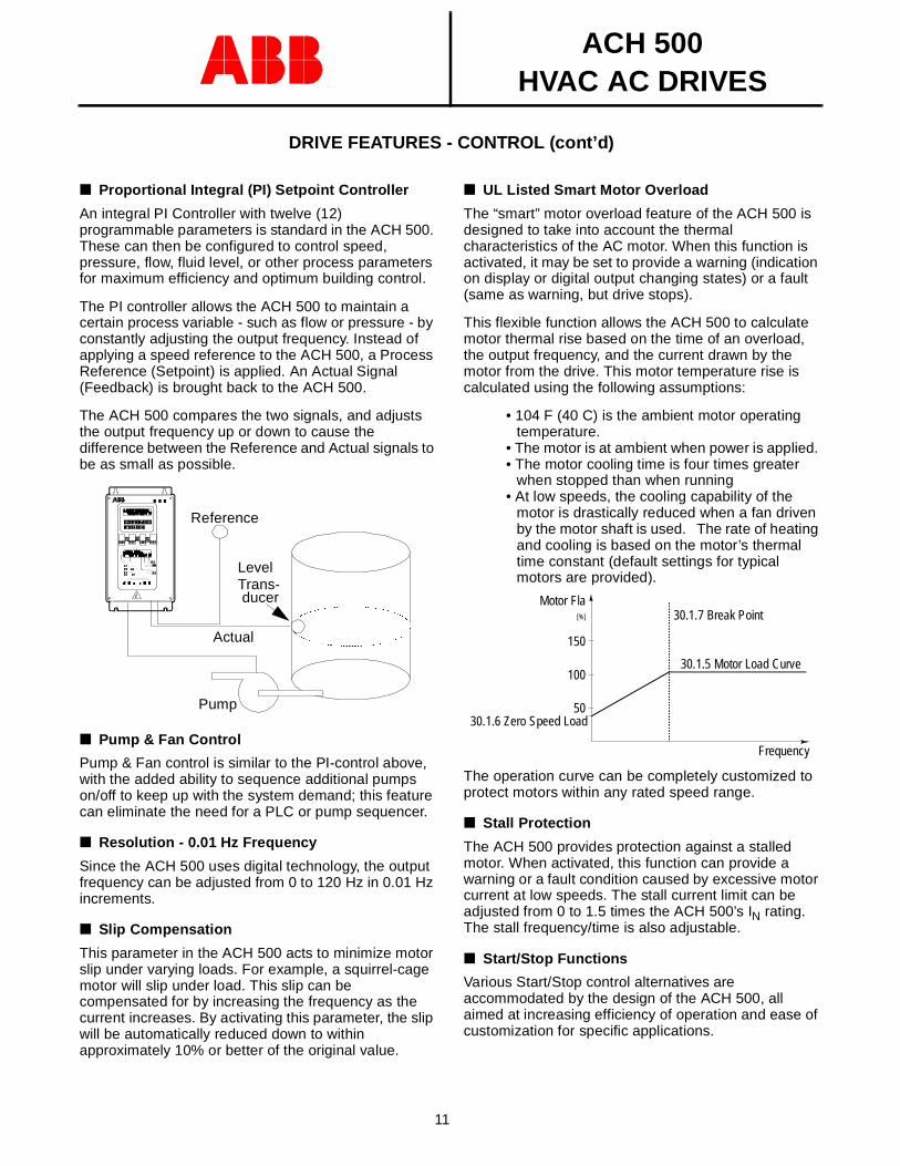
Proportional Integral (PI) Setpoint Controller
An integral PI Controller with twelve (12) programmable parameters is standard in the ACH 500. These can then be configured to control speed, pressure, flow, fluid level, or other process parameters for maximum efficiency and optimum building control.
The PI controller allows the ACH 500 to maintain a certain process variable - such as flow or pressure - by constantly adjusting the output frequency. Instead of applying a speed reference to the ACH 500, a Process Reference (Setpoint) is applied. An Actual Signal (Feedback) is brought back to the ACH 500.
The ACH 500 compares the two signals, and adjusts the output frequency up or down to cause the difference between the Reference and Actual signals to be as small as possible.
Pump & Fan Control
Pump & Fan control is similar to the PI-control above, with the added ability to sequence additional pumps on/off to keep up with the system demand; this feature can eliminate the need for a PLC or pump sequencer.
Resolution - 0.01 Hz Frequency
Since the ACH 500 uses digital technology, the output frequency can be adjusted from 0 to 120 Hz in 0.01 Hz increments.
Slip Compensation
This parameter in the ACH 500 acts to minimize motor slip under varying loads. For example, a squirrel-cage motor will slip under load. This slip can be compensated for by increasing the frequency as the current increases. By activating this parameter, the slip will be automatically reduced down to within approximately 10% or better of the original value.
AAAAAAAAAAAAAAAAAAAAAAAAAAAAAAAA
AAAAAAAAAAAAAAAAAAAAAAAAAAAAAAAA
AAAAAAAAAAAAAAAAAAAAAAAAAAAAAAAA
AAAAAAAAAAAAAAAAAAAAAAAAAAAAAAAA
AAAAAAAAAAAAAAAAAAAAAAAAAAAAAAAA
AAAAAAAAAAAAAAAAAAAAAAAA
AA
AAAAAAAAAAAAAAAAAAAAAAAAAAAAAAAAAAAAA
AAAAAAAAAAAAAA
AAAA
AAAA
Actual
Reference
LevelTrans-ducer
Pump
UL Listed Smart Motor Overload
The “smart” motor overload feature of the ACH 500 is designed to take into account the thermal characteristics of the AC motor. When this function is activated, it may be set to provide a warning (indication on display or digital output changing states) or a fault (same as warning, but drive stops).
This flexible function allows the ACH 500 to calculate motor thermal rise based on the time of an overload, the output frequency, and the current drawn by the motor from the drive. This motor temperature rise is calculated using the following assumptions:
• 104 F (40 C) is the ambient motor operating temperature.
• The motor is at ambient when power is applied. • The motor cooling time is four times greater
when stopped than when running• At low speeds, the cooling capability of the
motor is drastically reduced when a fan driven by the motor shaft is used. The rate of heating and cooling is based on the motor’s thermal time constant (default settings for typical motors are provided).
The operation curve can be completely customized to protect motors within any rated speed range.
Stall Protection
The ACH 500 provides protection against a stalled motor. When activated, this function can provide a warning or a fault condition caused by excessive motor current at low speeds. The stall current limit can be adjusted from 0 to 1.5 times the ACH 500’s IN rating. The stall frequency/time is also adjustable.
Start/Stop Functions
Various Start/Stop control alternatives are accommodated by the design of the ACH 500, all aimed at increasing efficiency of operation and ease of customization for specific applications.
AAAAAAAAAAAAAAAAAAAAAAAAAA
50
100
150
[%]
30.1.6 Zero Speed Load
30.1.5 Motor Load Curve
30.1.7 Break PointMotor Fla
Frequency
ACH 500HVAC AC DRIVES
12
DRIVE FEATURES - CONTROL (cont’d)
Motor starting torque of 180% of the rated torque can be achieved by selecting Start with torque boost. This avoids oversizing the drive and guarantees reliable starting of even the heaviest loads. (Note - The ACH 500 is designed to operate NEMA design B motors with a ratio of breakdown torque to rated torque of 2.6 to 2.9.)
Flying Start
The Flying Start function allows the ACH 500 to match its output frequency to the rotational speed of a rotating motor. The ACH 500 is able to smoothly resume operation without forcing the motor to zero speed before accelerating.
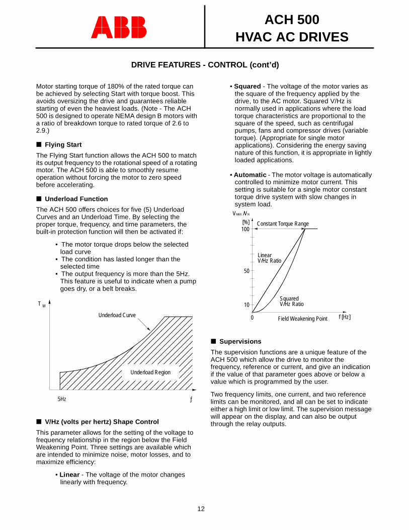
Underload Function
The ACH 500 offers choices for five (5) Underload Curves and an Underload Time. By selecting the proper torque, frequency, and time parameters, the built-in protection function will then be activated if:
• The motor torque drops below the selected load curve
• The condition has lasted longer than the selected time
• The output frequency is more than the 5Hz. This feature is useful to indicate when a pump goes dry, or a belt breaks.
V/Hz (volts per hertz) Shape Control
This parameter allows for the setting of the voltage to frequency relationship in the region below the Field Weakening Point. Three settings are available which are intended to minimize noise, motor losses, and to maximize efficiency:
• Linear - The voltage of the motor changes linearly with frequency.
Underload Curve
T M
5Hz ƒ
Underload Region
• Squared - The voltage of the motor varies as the square of the frequency applied by the drive, to the AC motor. Squared V/Hz is normally used in applications where the load torque characteristics are proportional to the square of the speed, such as centrifugal pumps, fans and compressor drives (variable torque). (Appropriate for single motor applications). Considering the energy saving nature of this function, it is appropriate in lightly loaded applications.
• Automatic - The motor voltage is automatically controlled to minimize motor current. This setting is suitable for a single motor constant torque drive system with slow changes in system load.
Supervisions
The supervision functions are a unique feature of the ACH 500 which allow the drive to monitor the frequency, reference or current, and give an indication if the value of that parameter goes above or below a value which is programmed by the user.
Two frequency limits, one current, and two reference limits can be monitored, and all can be set to indicate either a high limit or low limit. The supervision message will appear on the display, and can also be output through the relay outputs.
f [Hz]0
Constant Torque Range
10
50
100[%]
VMAX /VN
AAAAAAAAAAAAAAAAAAAAAAAAAAAAAAAAAAAAAAAAAAAAAAAAAAAAAAAAAAAAAAAAAA
LinearV/Hz Ratio
SquaredV/Hz Ratio
Field Weakening Point
ACH 500HVAC AC DRIVES
13
OPTIONAL FEATURES
3 to 15 PSI Speed Input
Option board with pressure to electrical transducer to accept a 3 to 15 PSI pneumatic signal as a speed reference for the ACH 500. Also included on this board are two isolators for the digital inputs, allowing them to accept a voltage (24 to 250 VAC or VDC) to activate a digital input, such as 115 VAC start signal.
115 VAC Relay Input Board
Four inputs for 115 VAC signals to activate digital inputs. 115 VAC can be supplied from this board or external source. Applying 115 VAC energizes a relay which can be connected to any digital input. Ideal for 115 VAC from triac output of a PLC.
I/O Extension Board
Option board to provide isolated I/O in addition to the existing I/O on the ACH 500. The board contains:2 Isolated analog inputs3 Isolated digital inputs2 Isolated analog outputs2 Relay outputs
LonWorks Communication Board
78 kBits/s transfer coupled interface board for LonWorks network. Communication board is mounted in the lower option board slot.
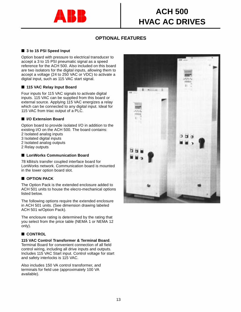
OPTION PACK
The Option Pack is the extended enclosure added to ACH 501 units to house the elecro-mechanical options listed below.
The following options require the extended enclosure in ACH 501 units. (See dimension drawing labeled ACH 501 w/Option Pack).
The enclosure rating is determined by the rating that you select from the price table (NEMA 1 or NEMA 12 only).
CONTROL
115 VAC Control Transformer & Terminal Board . Terminal Board for convenient connection of all field control wiring, including all drive inputs and outputs. Includes 115 VAC Start input. Control voltage for start and safety interlocks is 115 VAC.
Also includes 150 VA control transformer, and terminals for field use (approximately 100 VA available).
photo of ACH 501 with optionpack
ACH 500HVAC AC DRIVES
14
OPTIONAL FEATURES - (cont’d)
INPUT OPTIONS
Circuit Breaker . Thermal Magnetic Circuit Breaker, thru-the-door interlock type, pad-lockable in the OFF position. The circuit breaker option is required with bypass in ACH 502 units.
Disconnect Switch . Non-fused disconnect switch, thru-the-door interlock type, pad-lockable in the OFF position. When bypass is supplied (on ACH 501), fuses are supplied with the disconnect switch to provide branch circuit protection for the motor in bypass.
Line Reactor. 3% and 5% impedance line reactors are available to limit the harmonics back to the power line. Reactors are mounted in the option pack on R2 through R5 units, and in the standard enclosure on R6 through R9 units (R8 unit with line reactor will be supplied in the two bay enclosure).
BYPASS OPTIONS
Manual Bypass With Service Switch . Allows motor to be connected to line power and operate at full speed instead of being powered by the drive. In bypass, the start signals and safety interlocks are still active. Switching to bypass automatically disables the drive.
Motor Overload option may be required to meet local codes.
Control Option B with 115 VAC control transformer is required with all bypass options.
The circuit breaker option is required with bypass in ACH 502 units.
The bypass option includes Normal and Bypass Pilot Lights, and an external fault circuit with an indicating lamp which illuminates when any external safety device has shut down the motor. All pilot lights are push-to-test type.
An additional switch allows power to be removed from the drive for servicing, while the motor operates from line power. Switch is mounted internally to prevent unauthorized persons from disrupting operation.
When bypass is selected, power is removed from the drive.
Automatic Bypass . Automatically transfers motor to line power after the drive trips out on a protective trip. If automatic restart has been enabled on the drive, the drive will attempt to automatically restart before the motor is transferred to line power. (Requires Manual Bypass option). Consumes one of the available relay outputs.
THERMAL OVERLOAD RELAYS:
Motor Overload Relay (MOL). Standard, manually resettable, bimetallic, motor overload relay with Class 20 trip curve provides thermal motor protection when operating from the drive, and across the line with Bypass option. Thru-the-door reset button is included. NOTE: MOL must be sized to the drive for UL Listing.
Extension Enclosure
An extension enclosure is available for the ACH 501. The extension enclosure is a small enclosure (smaller than the Option Pack listed above) that can be ordered empty (for customer use) or with a door interlocked input disconnect switch. When supplied with the disconnect, the cover on the extension enclosure extends to cover the drive enclosure, interlocking the drive with the disconnect switch. The drive and extension enclosure are mounted on a common back panel.
See page 24 for dimensions.
ACH 500HVAC AC DRIVES
15
TECHNICAL DATA
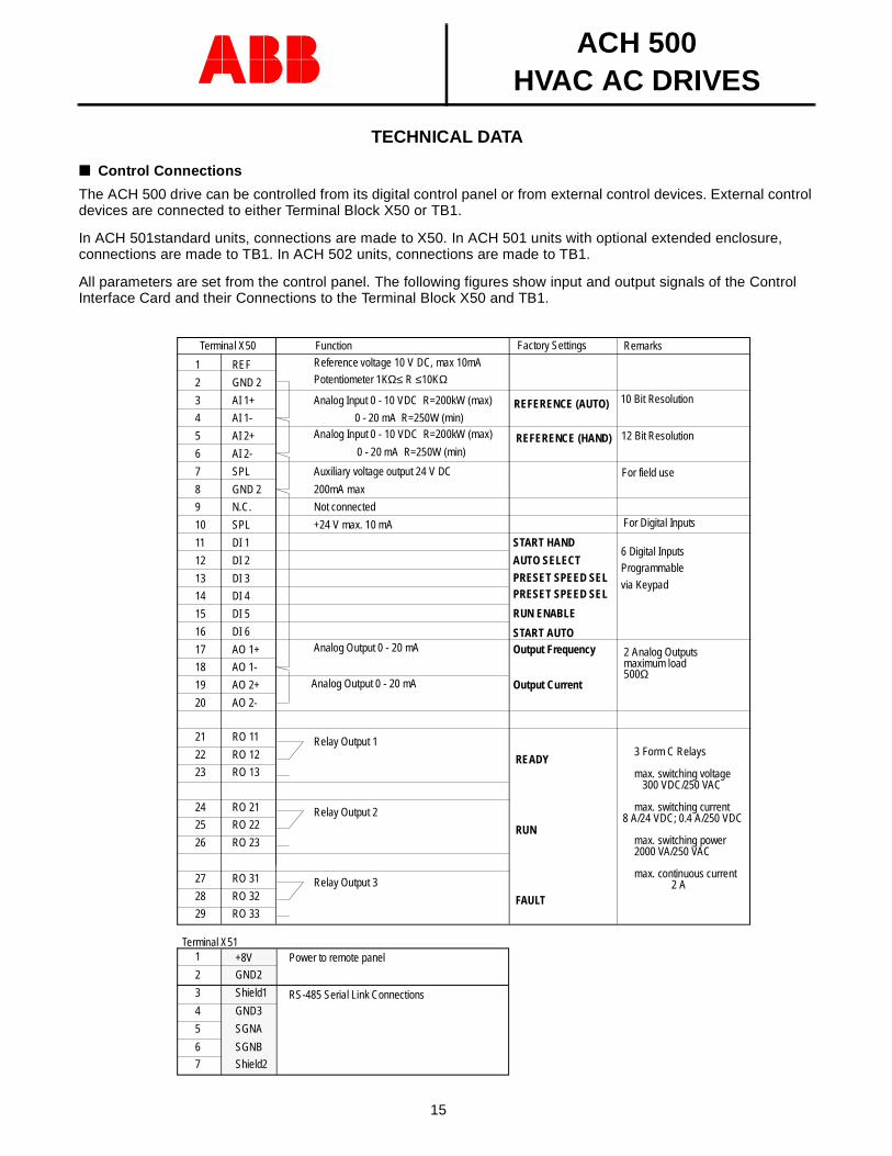
Control Connections
The ACH 500 drive can be controlled from its digital control panel or from external control devices. External control devices are connected to either Terminal Block X50 or TB1.
In ACH 501standard units, connections are made to X50. In ACH 501 units with optional extended enclosure, connections are made to TB1. In ACH 502 units, connections are made to TB1.
All parameters are set from the control panel. The following figures show input and output signals of the Control Interface Card and their Connections to the Terminal Block X50 and TB1.
Relay Output 2
RUN
1
2
3
4
5
6
7
8
9
10
11
12
13
14
15
16
17
18
19
20
21
22
23
24
25
26
27
28
29
REF
GND 2
AI 1+
AI 1-
AI 2+
AI 2-
SPL
GND 2
N.C.
SPL
DI 1
DI 2
DI 3
DI 4
DI 5
DI 6
AO 1+
AO 1-
AO 2+
AO 2-
RO 11
RO 12
RO 13
RO 21
RO 22
RO 23
RO 31
RO 32
RO 33
Terminal X50 Function
Reference voltage 10 V DC, max 10mA
Analog Input 0 - 10 VDC R=200kW (max)
0 - 20 mA R=250W (min)
Auxiliary voltage output 24 V DC
200mA max
Not connected
+24 V max. 10 mA
START HAND
AUTO SELECT
START AUTO
PRESET SPEED SEL
Output FrequencyAnalog Output 0 - 20 mA
Output Current
Relay Output 1
READY
Relay Output 3
FAULT
1
2
3
4
5
6
+8V Power to remote panel
Potentiometer 1KΩ≤ R ≤10KΩ
RUN ENABLE
PRESET SPEED SEL
RS-485 Serial Link Connections
GND2
Shield1
GND3
SGNA
SGNB
7 Shield2
Terminal X51
Analog Input 0 - 10 VDC R=200kW (max)
0 - 20 mA R=250W (min)
10 Bit Resolution
For field use
12 Bit Resolution
For Digital Inputs
6 Digital InputsProgrammable
via Keypad
2 Analog Outputsmaximum load500Ω
3 Form C Relays
max. switching voltage300 VDC/250 VAC
max. switching current8 A/24 VDC; 0.4 A/250 VDC
max. switching power2000 VA/250 VAC
max. continuous current2 A
Analog Output 0 - 20 mA
RemarksFactory Settings
REFERENCE (AUTO)
REFERENCE (HAND)
ACH 500HVAC AC DRIVES
16
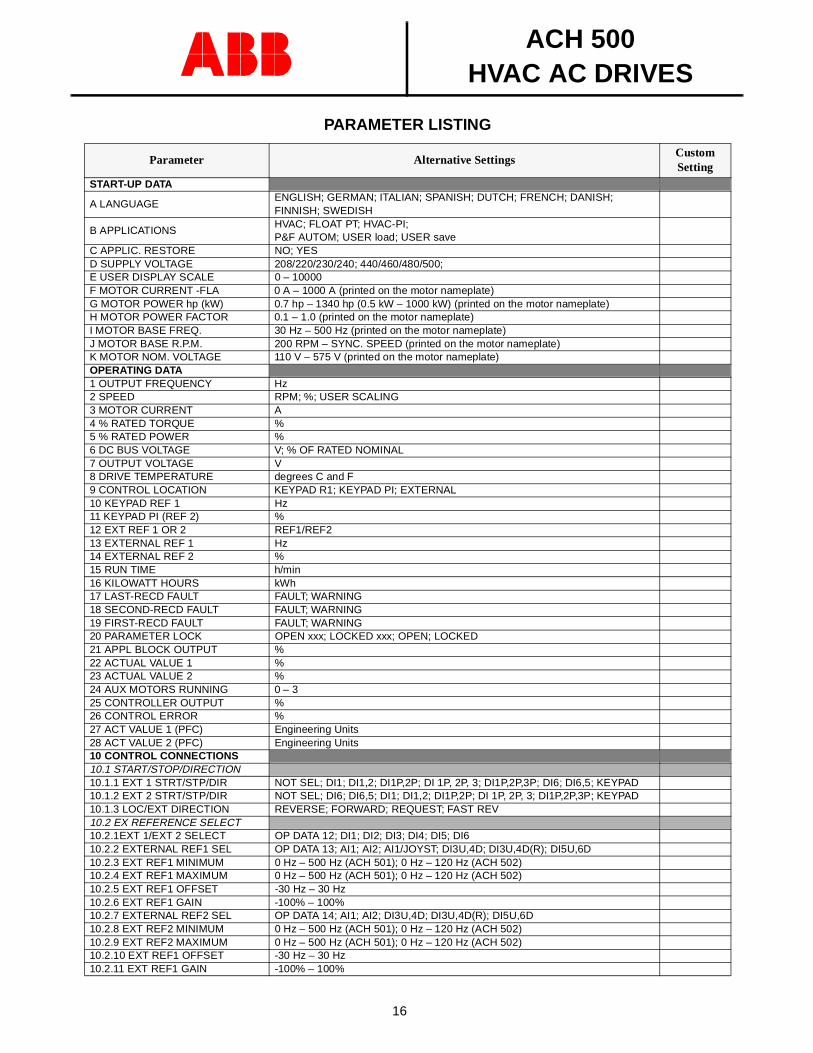
PARAMETER LISTING
Parameter Alternative SettingsCustom Setting
START-UP DATA
A LANGUAGEENGLISH; GERMAN; ITALIAN; SPANISH; DUTCH; FRENCH; DANISH; FINNISH; SWEDISH
B APPLICATIONSHVAC; FLOAT PT; HVAC-PI; P&F AUTOM; USER load; USER save
C APPLIC. RESTORE NO; YESD SUPPLY VOLTAGE 208/220/230/240; 440/460/480/500; E USER DISPLAY SCALE 0 – 10000F MOTOR CURRENT -FLA 0 A – 1000 A (printed on the motor nameplate)G MOTOR POWER hp (kW) 0.7 hp – 1340 hp (0.5 kW – 1000 kW) (printed on the motor nameplate)H MOTOR POWER FACTOR 0.1 – 1.0 (printed on the motor nameplate)I MOTOR BASE FREQ. 30 Hz – 500 Hz (printed on the motor nameplate)J MOTOR BASE R.P.M. 200 RPM – SYNC. SPEED (printed on the motor nameplate)K MOTOR NOM. VOLTAGE 110 V – 575 V (printed on the motor nameplate)OPERATING DATA1 OUTPUT FREQUENCY Hz2 SPEED RPM; %; USER SCALING3 MOTOR CURRENT A4 % RATED TORQUE %5 % RATED POWER %6 DC BUS VOLTAGE V; % OF RATED NOMINAL7 OUTPUT VOLTAGE V8 DRIVE TEMPERATURE degrees C and F9 CONTROL LOCATION KEYPAD R1; KEYPAD PI; EXTERNAL10 KEYPAD REF 1 Hz11 KEYPAD PI (REF 2) %12 EXT REF 1 OR 2 REF1/REF213 EXTERNAL REF 1 Hz14 EXTERNAL REF 2 %15 RUN TIME h/min16 KILOWATT HOURS kWh17 LAST-RECD FAULT FAULT; WARNING18 SECOND-RECD FAULT FAULT; WARNING19 FIRST-RECD FAULT FAULT; WARNING20 PARAMETER LOCK OPEN xxx; LOCKED xxx; OPEN; LOCKED21 APPL BLOCK OUTPUT %22 ACTUAL VALUE 1 %23 ACTUAL VALUE 2 %24 AUX MOTORS RUNNING 0 – 325 CONTROLLER OUTPUT %26 CONTROL ERROR %27 ACT VALUE 1 (PFC) Engineering Units28 ACT VALUE 2 (PFC) Engineering Units10 CONTROL CONNECTIONS10.1 START/STOP/DIRECTION10.1.1 EXT 1 STRT/STP/DIR NOT SEL; DI1; DI1,2; DI1P,2P; DI 1P, 2P, 3; DI1P,2P,3P; DI6; DI6,5; KEYPAD10.1.2 EXT 2 STRT/STP/DIR NOT SEL; DI6; DI6,5; DI1; DI1,2; DI1P,2P; DI 1P, 2P, 3; DI1P,2P,3P; KEYPAD10.1.3 LOC/EXT DIRECTION REVERSE; FORWARD; REQUEST; FAST REV10.2 EX REFERENCE SELECT10.2.1EXT 1/EXT 2 SELECT OP DATA 12; DI1; DI2; DI3; DI4; DI5; DI610.2.2 EXTERNAL REF1 SEL OP DATA 13; AI1; AI2; AI1/JOYST; DI3U,4D; DI3U,4D(R); DI5U,6D10.2.3 EXT REF1 MINIMUM 0 Hz – 500 Hz (ACH 501); 0 Hz – 120 Hz (ACH 502)10.2.4 EXT REF1 MAXIMUM 0 Hz – 500 Hz (ACH 501); 0 Hz – 120 Hz (ACH 502)10.2.5 EXT REF1 OFFSET -30 Hz – 30 Hz10.2.6 EXT REF1 GAIN -100% – 100% 10.2.7 EXTERNAL REF2 SEL OP DATA 14; AI1; AI2; DI3U,4D; DI3U,4D(R); DI5U,6D10.2.8 EXT REF2 MINIMUM 0 Hz – 500 Hz (ACH 501); 0 Hz – 120 Hz (ACH 502)10.2.9 EXT REF2 MAXIMUM 0 Hz – 500 Hz (ACH 501); 0 Hz – 120 Hz (ACH 502)10.2.10 EXT REF1 OFFSET -30 Hz – 30 Hz10.2.11 EXT REF1 GAIN -100% – 100%
ACH 500HVAC AC DRIVES
17
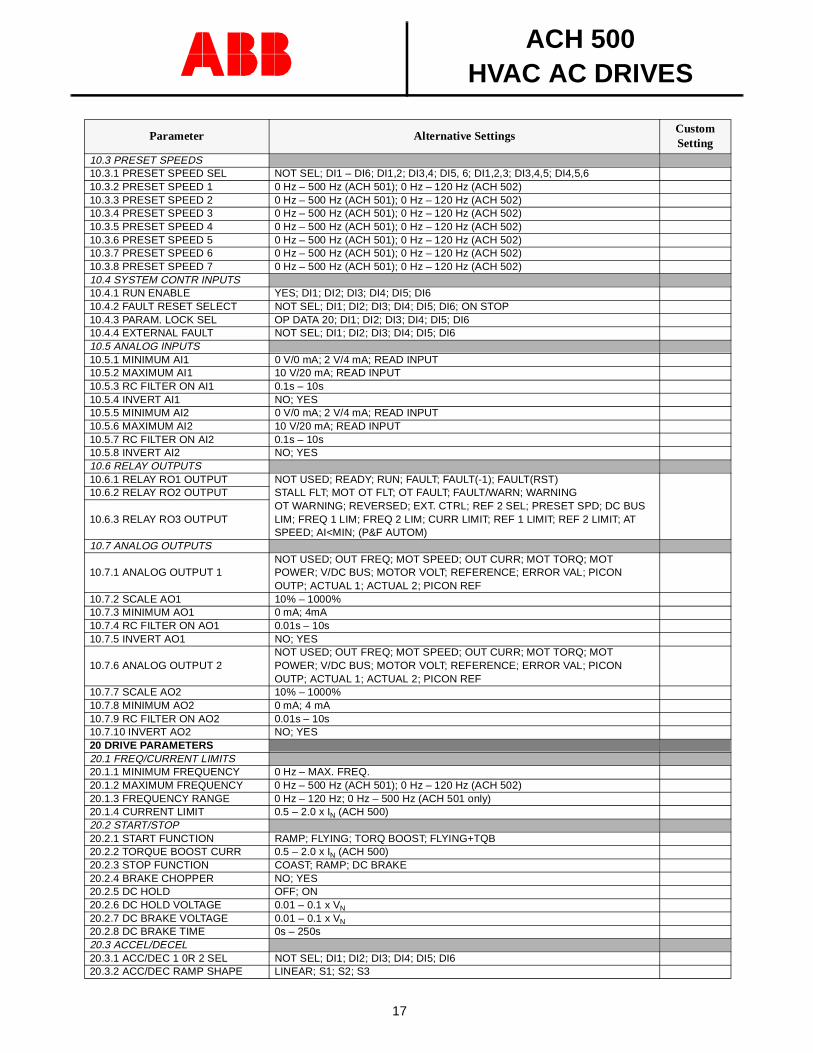
10.3 PRESET SPEEDS10.3.1 PRESET SPEED SEL NOT SEL; DI1 – DI6; DI1,2; DI3,4; DI5, 6; DI1,2,3; DI3,4,5; DI4,5,610.3.2 PRESET SPEED 1 0 Hz – 500 Hz (ACH 501); 0 Hz – 120 Hz (ACH 502)10.3.3 PRESET SPEED 2 0 Hz – 500 Hz (ACH 501); 0 Hz – 120 Hz (ACH 502)10.3.4 PRESET SPEED 3 0 Hz – 500 Hz (ACH 501); 0 Hz – 120 Hz (ACH 502)10.3.5 PRESET SPEED 4 0 Hz – 500 Hz (ACH 501); 0 Hz – 120 Hz (ACH 502)10.3.6 PRESET SPEED 5 0 Hz – 500 Hz (ACH 501); 0 Hz – 120 Hz (ACH 502)10.3.7 PRESET SPEED 6 0 Hz – 500 Hz (ACH 501); 0 Hz – 120 Hz (ACH 502)10.3.8 PRESET SPEED 7 0 Hz – 500 Hz (ACH 501); 0 Hz – 120 Hz (ACH 502)10.4 SYSTEM CONTR INPUTS10.4.1 RUN ENABLE YES; DI1; DI2; DI3; DI4; DI5; DI610.4.2 FAULT RESET SELECT NOT SEL; DI1; DI2; DI3; DI4; DI5; DI6; ON STOP10.4.3 PARAM. LOCK SEL OP DATA 20; DI1; DI2; DI3; DI4; DI5; DI610.4.4 EXTERNAL FAULT NOT SEL; DI1; DI2; DI3; DI4; DI5; DI610.5 ANALOG INPUTS10.5.1 MINIMUM AI1 0 V/0 mA; 2 V/4 mA; READ INPUT10.5.2 MAXIMUM AI1 10 V/20 mA; READ INPUT10.5.3 RC FILTER ON AI1 0.1s – 10s10.5.4 INVERT AI1 NO; YES10.5.5 MINIMUM AI2 0 V/0 mA; 2 V/4 mA; READ INPUT10.5.6 MAXIMUM AI2 10 V/20 mA; READ INPUT10.5.7 RC FILTER ON AI2 0.1s – 10s10.5.8 INVERT AI2 NO; YES10.6 RELAY OUTPUTS10.6.1 RELAY RO1 OUTPUT NOT USED; READY; RUN; FAULT; FAULT(-1); FAULT(RST)
STALL FLT; MOT OT FLT; OT FAULT; FAULT/WARN; WARNINGOT WARNING; REVERSED; EXT. CTRL; REF 2 SEL; PRESET SPD; DC BUS LIM; FREQ 1 LIM; FREQ 2 LIM; CURR LIMIT; REF 1 LIMIT; REF 2 LIMIT; AT SPEED; AI<MIN; (P&F AUTOM)
10.6.2 RELAY RO2 OUTPUT
10.6.3 RELAY RO3 OUTPUT
10.7 ANALOG OUTPUTS
10.7.1 ANALOG OUTPUT 1NOT USED; OUT FREQ; MOT SPEED; OUT CURR; MOT TORQ; MOT POWER; V/DC BUS; MOTOR VOLT; REFERENCE; ERROR VAL; PICON OUTP; ACTUAL 1; ACTUAL 2; PICON REF
10.7.2 SCALE AO1 10% – 1000%10.7.3 MINIMUM AO1 0 mA; 4mA10.7.4 RC FILTER ON AO1 0.01s – 10s10.7.5 INVERT AO1 NO; YES
10.7.6 ANALOG OUTPUT 2NOT USED; OUT FREQ; MOT SPEED; OUT CURR; MOT TORQ; MOT POWER; V/DC BUS; MOTOR VOLT; REFERENCE; ERROR VAL; PICON OUTP; ACTUAL 1; ACTUAL 2; PICON REF
10.7.7 SCALE AO2 10% – 1000%10.7.8 MINIMUM AO2 0 mA; 4 mA10.7.9 RC FILTER ON AO2 0.01s – 10s10.7.10 INVERT AO2 NO; YES20 DRIVE PARAMETERS20.1 FREQ/CURRENT LIMITS20.1.1 MINIMUM FREQUENCY 0 Hz – MAX. FREQ.20.1.2 MAXIMUM FREQUENCY 0 Hz – 500 Hz (ACH 501); 0 Hz – 120 Hz (ACH 502)20.1.3 FREQUENCY RANGE 0 Hz – 120 Hz; 0 Hz – 500 Hz (ACH 501 only)20.1.4 CURRENT LIMIT 0.5 – 2.0 x IN (ACH 500)20.2 START/STOP20.2.1 START FUNCTION RAMP; FLYING; TORQ BOOST; FLYING+TQB20.2.2 TORQUE BOOST CURR 0.5 – 2.0 x IN (ACH 500)20.2.3 STOP FUNCTION COAST; RAMP; DC BRAKE20.2.4 BRAKE CHOPPER NO; YES20.2.5 DC HOLD OFF; ON20.2.6 DC HOLD VOLTAGE 0.01 – 0.1 x VN
20.2.7 DC BRAKE VOLTAGE 0.01 – 0.1 x VN
20.2.8 DC BRAKE TIME 0s – 250s20.3 ACCEL/DECEL20.3.1 ACC/DEC 1 0R 2 SEL NOT SEL; DI1; DI2; DI3; DI4; DI5; DI620.3.2 ACC/DEC RAMP SHAPE LINEAR; S1; S2; S3
Parameter Alternative SettingsCustom Setting
ACH 500HVAC AC DRIVES
18
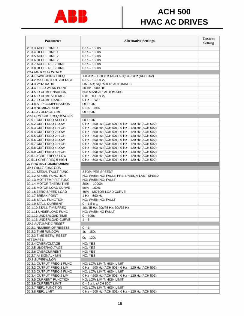
20.3.3 ACCEL TIME 1 0.1s – 1800s20.3.4 DECEL TIME 1 0.1s – 1800s20.3.5 ACCEL TIME 2 0.1s – 1800s20.3.6 DECEL TIME 2 0.1s – 1800s20.3.7 ACCEL REF2 TIME 0.1s – 1800s20.3.8 DECEL REF2 TIME 0.1s – 1800s20.4 MOTOR CONTROL20.4.1 SWITCHING FREQ 1.0 kHz – 12.0 kHz (ACH 501); 3.0 kHz (ACH 502)20.4.2 MAX OUTPUT VOLTAGE 0.15 – 1.05 x VN
20.4.3 V/HZ RATIO LINEAR; SQUARED; AUTOMATIC20.4.4 FIELD WEAK POINT 30 Hz – 500 Hz20.4.5 IR COMPENSATION NO; MANUAL; AUTOMATIC20.4.6 IR COMP VOLTAGE 0.01 – 0.15 x VN
20.4.7 IR COMP RANGE 0 Hz – FWP20.4.8 SLIP COMPENSATION OFF; ON20.4.9 NOMINAL SLIP 0.1% – 10%20.4.10 VOLTAGE LIMIT OFF; ON20.5 CRITICAL FREQUENCIES20.5.1 CRIT FREQ SELECT OFF; ON20.5.2 CRIT FREQ 1 LOW 0 Hz – 500 Hz (ACH 501); 0 Hz – 120 Hz (ACH 502)20.5.3 CRIT FREQ 1 HIGH 0 Hz – 500 Hz (ACH 501); 0 Hz – 120 Hz (ACH 502)20.5.4 CRIT FREQ 2 LOW 0 Hz – 500 Hz (ACH 501); 0 Hz – 120 Hz (ACH 502)20.5.5 CRIT FREQ 2 HIGH 0 Hz – 500 Hz (ACH 501); 0 Hz – 120 Hz (ACH 502)20.5.6 CRIT FREQ 3 LOW 0 Hz – 500 Hz (ACH 501); 0 Hz – 120 Hz (ACH 502)20.5.7 CRIT FREQ 3 HIGH 0 Hz – 500 Hz (ACH 501); 0 Hz – 120 Hz (ACH 502)20.5.8 CRIT FREQ 4 LOW 0 Hz – 500 Hz (ACH 501); 0 Hz – 120 Hz (ACH 502)20.5.9 CRIT FREQ 4 HIGH 0 Hz – 500 Hz (ACH 501); 0 Hz – 120 Hz (ACH 502)20.5.10 CRIT FREQ 5 LOW 0 Hz – 500 Hz (ACH 501); 0 Hz – 120 Hz (ACH 502)20.5.11 CRIT FREQ 5 HIGH 0 Hz – 500 Hz (ACH 501); 0 Hz – 120 Hz (ACH 502)30 PROTECTION/INFORMAT30.1 FAULT FUNCTION30.1.1 SERIAL FAULT FUNC STOP; PRE SPEED730.1.2 AI <MIN FUNCTION NO; WARNING; FAULT; PRE SPEED7; LAST SPEED30.1.3 MOT TEMP FLT FUNC NO; WARNING; FAULT30.1.4 MOTOR THERM TIME 300s – 10000s30.1.5 MOTOR LOAD CURVE 50% – 150%30.1.6 ZERO SPEED LOAD 40% – MOTOR LOAD CURVE30.1.7 BREAK POINT 1 Hz – 500 Hz30.1.8 STALL FUNCTION NO; WARNING; FAULT30.1.9 STALL CURRENT 0 – 1.5 x IN 30.1.10 STALL TIME/FREQ 10s/15 Hz; 20s/25 Hz; 30s/35 Hz30.1.11 UNDERLOAD FUNC NO; WARNING FAULT30.1.12 UNDERLOAD TIME 0 – 600s30.1.13 UNDERLOAD CURVE 1 – 530.2 AUTOMATIC RESET30.2.1 NUMBER OF RESETS 0 – 530.2.2 TIME WINDOW 1s – 180s30.2.3 TIME BETW. RESET ATTEMPTS
0s – 120s
30.2.4 OVERVOLTAGE NO; YES30.2.5 UNDERVOLTAGE NO; YES30.2.6 OVERCURRENT NO; YES30.2.7 AI SIGNAL <MIN NO; YES30.3 SUPERVISION30.3.1 OUTPUT FREQ 1 FUNC NO; LOW LIMIT; HIGH LIMIT30.3.2 OUTPUT FREQ 1 LIM 0 Hz – 500 Hz (ACH 501); 0 Hz – 120 Hz (ACH 502)30.3.3 OUTPUT FREQ 2 FUNC NO; LOW LIMIT; HIGH LIMIT30.3.4 OUTPUT FREQ 2 LIM 0 Hz – 500 Hz (ACH 501); 0 Hz – 120 Hz (ACH 502)30.3.5 CURRENT FUNCTION NO; LOW LIMIT; HIGH LIMIT30.3.6 CURRENT LIMIT 0 – 2 x IN (ACH 500)30.3.7 REF1 FUNCTION NO; LOW LIMIT; HIGH LIMIT30.3.8 REF1 LIMIT 0 Hz – 500 Hz (ACH 501); 0 Hz – 120 Hz (ACH 502)
Parameter Alternative SettingsCustom Setting
ACH 500HVAC AC DRIVES
19
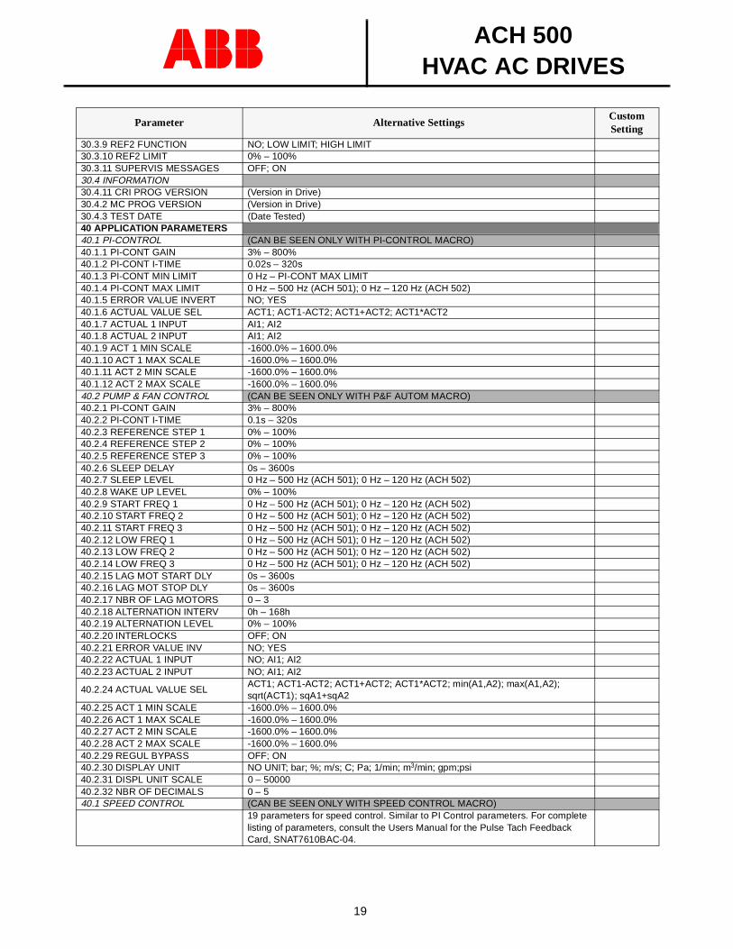
30.3.9 REF2 FUNCTION NO; LOW LIMIT; HIGH LIMIT30.3.10 REF2 LIMIT 0% – 100%30.3.11 SUPERVIS MESSAGES OFF; ON30.4 INFORMATION30.4.11 CRI PROG VERSION (Version in Drive)30.4.2 MC PROG VERSION (Version in Drive)30.4.3 TEST DATE (Date Tested)40 APPLICATION PARAMETERS40.1 PI-CONTROL (CAN BE SEEN ONLY WITH PI-CONTROL MACRO)40.1.1 PI-CONT GAIN 3% – 800%40.1.2 PI-CONT I-TIME 0.02s – 320s40.1.3 PI-CONT MIN LIMIT 0 Hz – PI-CONT MAX LIMIT40.1.4 PI-CONT MAX LIMIT 0 Hz – 500 Hz (ACH 501); 0 Hz – 120 Hz (ACH 502)40.1.5 ERROR VALUE INVERT NO; YES40.1.6 ACTUAL VALUE SEL ACT1; ACT1-ACT2; ACT1+ACT2; ACT1*ACT240.1.7 ACTUAL 1 INPUT AI1; AI240.1.8 ACTUAL 2 INPUT AI1; AI240.1.9 ACT 1 MIN SCALE -1600.0% – 1600.0%40.1.10 ACT 1 MAX SCALE -1600.0% – 1600.0%40.1.11 ACT 2 MIN SCALE -1600.0% – 1600.0%40.1.12 ACT 2 MAX SCALE -1600.0% – 1600.0%40.2 PUMP & FAN CONTROL (CAN BE SEEN ONLY WITH P&F AUTOM MACRO)40.2.1 PI-CONT GAIN 3% – 800%40.2.2 PI-CONT I-TIME 0.1s – 320s40.2.3 REFERENCE STEP 1 0% – 100%40.2.4 REFERENCE STEP 2 0% – 100%40.2.5 REFERENCE STEP 3 0% – 100%40.2.6 SLEEP DELAY 0s – 3600s40.2.7 SLEEP LEVEL 0 Hz – 500 Hz (ACH 501); 0 Hz – 120 Hz (ACH 502)40.2.8 WAKE UP LEVEL 0% – 100%40.2.9 START FREQ 1 0 Hz – 500 Hz (ACH 501); 0 Hz – 120 Hz (ACH 502)40.2.10 START FREQ 2 0 Hz – 500 Hz (ACH 501); 0 Hz – 120 Hz (ACH 502)40.2.11 START FREQ 3 0 Hz – 500 Hz (ACH 501); 0 Hz – 120 Hz (ACH 502)40.2.12 LOW FREQ 1 0 Hz – 500 Hz (ACH 501); 0 Hz – 120 Hz (ACH 502)40.2.13 LOW FREQ 2 0 Hz – 500 Hz (ACH 501); 0 Hz – 120 Hz (ACH 502)40.2.14 LOW FREQ 3 0 Hz – 500 Hz (ACH 501); 0 Hz – 120 Hz (ACH 502)40.2.15 LAG MOT START DLY 0s – 3600s40.2.16 LAG MOT STOP DLY 0s – 3600s40.2.17 NBR OF LAG MOTORS 0 – 340.2.18 ALTERNATION INTERV 0h – 168h40.2.19 ALTERNATION LEVEL 0% – 100%40.2.20 INTERLOCKS OFF; ON40.2.21 ERROR VALUE INV NO; YES40.2.22 ACTUAL 1 INPUT NO; AI1; AI240.2.23 ACTUAL 2 INPUT NO; AI1; AI2
40.2.24 ACTUAL VALUE SELACT1; ACT1-ACT2; ACT1+ACT2; ACT1*ACT2; min(A1,A2); max(A1,A2); sqrt(ACT1); sqA1+sqA2
40.2.25 ACT 1 MIN SCALE -1600.0% – 1600.0%40.2.26 ACT 1 MAX SCALE -1600.0% – 1600.0%40.2.27 ACT 2 MIN SCALE -1600.0% – 1600.0%40.2.28 ACT 2 MAX SCALE -1600.0% – 1600.0%40.2.29 REGUL BYPASS OFF; ON40.2.30 DISPLAY UNIT NO UNIT; bar; %; m/s; C; Pa; 1/min; m3/min; gpm;psi40.2.31 DISPL UNIT SCALE 0 – 5000040.2.32 NBR OF DECIMALS 0 – 540.1 SPEED CONTROL (CAN BE SEEN ONLY WITH SPEED CONTROL MACRO)
19 parameters for speed control. Similar to PI Control parameters. For complete listing of parameters, consult the Users Manual for the Pulse Tach Feedback Card, SNAT7610BAC-04.
Parameter Alternative SettingsCustom Setting
ACH 500HVAC AC DRIVES
20
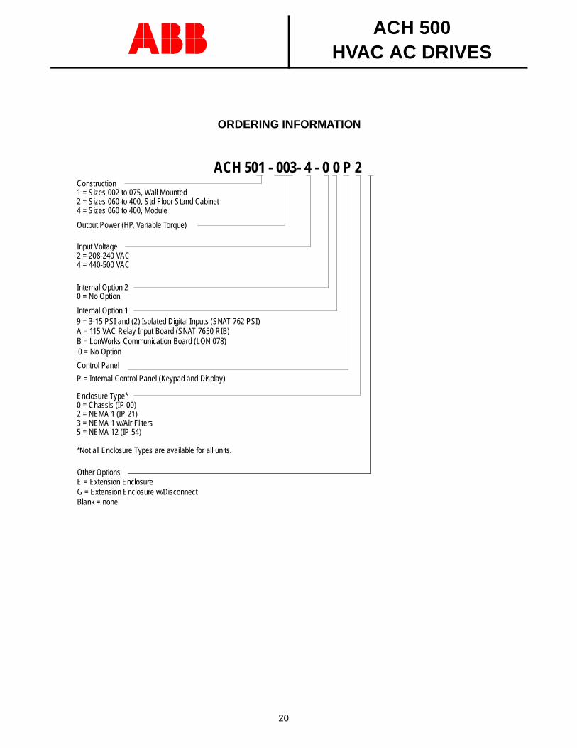
ORDERING INFORMATION
ACH 501 - 003- 4 - 0 0 P 2Construction1 = Sizes 002 to 075, Wall Mounted2 = Sizes 060 to 400, Std Floor Stand Cabinet4 = Sizes 060 to 400, Module
Output Power (HP, Variable Torque)
Input Voltage
4 = 440-500 VAC
Internal Option 20 = No Option
Internal Option 19 = 3-15 PSI and (2) Isolated Digital Inputs (SNAT 762 PSI)
0 = No Option
Control Panel
P = Internal Control Panel (Keypad and Display)
Enclosure Type*0 = Chassis (IP 00)2 = NEMA 1 (IP 21)3 = NEMA 1 w/Air Filters5 = NEMA 12 (IP 54)
*Not all Enclosure Types are available for all units.
2 = 208-240 VAC
A = 115 VAC Relay Input Board (SNAT 7650 RIB)B = LonWorks Communication Board (LON 078)
Other OptionsE = Extension EnclosureG = Extension Enclosure w/DisconnectBlank = none
ACH 500HVAC AC DRIVES
21
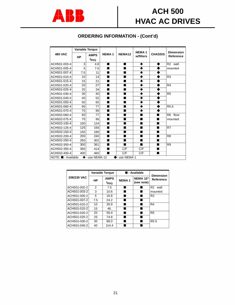
ORDERING INFORMATION - (Cont’d)
480 VAC
Variable Torque
NEMA 1 NEMA12NEMA 1w/filters
CHASSISDimension ReferenceHP
AMPSIRSQ
ACH501-003-4 3 4.8 ♣ R2 wallACH501-005-4 5 7.6 ♣ mountedACH501-007-4 7.5 11 ♣
ACH501-010-4 10 14 ♣ R3ACH501-015-4 15 21 ♣
ACH501-020-4 20 27 ♣ R4ACH501-025-4 25 34 ♣
ACH501-030-4 30 40 ♣ R5ACH501-040-4 40 52 ♣
ACH501-050-4 50 65 ♣
ACH501-060-4 60 77 ♣ R5.5ACH501-075-4 75 96 ♣
ACH502-060-4 60 77 R6 floorACH502-075-4 75 96 mountedACH502-100-4 100 124
ACH502-125-4 125 156 R7ACH502-150-4 150 180
ACH502-200-4 200 240 R8ACH502-250-4 250 302
ACH502-300-4 300 361 R9ACH502-350-4 350 414 C/F C/F
ACH502-400-4 400 460 C/F C/F
NOTE: - Available ♣ - use NEMA 12 - use NEMA 1
208/230 VAC
Variable Torque - AvailableDimension ReferenceHP
AMPSIRSQ
NEMA 1NEMA 12*(see note)
ACH501-002-2 2 7.5 R2 wallACH501-003-2 3 10.6 mountedACH501-005-2 5 16.8 R3ACH501-007-2 7.5 24.2
ACH501-010-2 10 30.9 R4ACH501-015-2 15 46.
ACH501-020-2 20 59.4 R5ACH501-025-2 25 74.8
ACH501-030-2 30 88.0 R5.5ACH501-040-2 40 114.4
ACH 500HVAC AC DRIVES
22
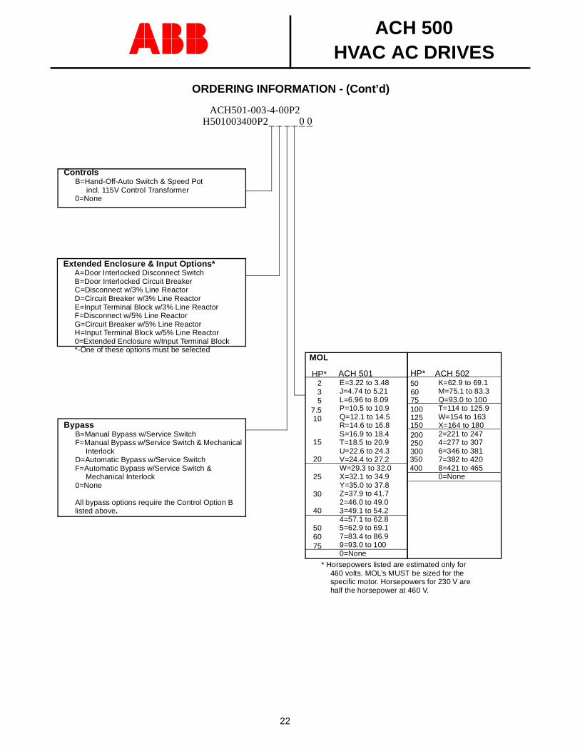
ORDERING INFORMATION - (Cont’d)
ACH501-003-4-00P2H501003400P2
ControlsB=Hand-Off-Auto Switch & Speed Pot
incl. 115V Control Transformer0=None
ACH 501E=3.22 to 3.48J=4.74 to 5.21L=6.96 to 8.09P=10.5 to 10.9Q=12.1 to 14.5R=14.6 to 16.8S=16.9 to 18.4T=18.5 to 20.9U=22.6 to 24.3V=24.4 to 27.2W=29.3 to 32.0X=32.1 to 34.9Y=35.0 to 37.8Z=37.9 to 41.72=46.0 to 49.03=49.1 to 54.24=57.1 to 62.85=62.9 to 69.17=83.4 to 86.99=93.0 to 1000=None
50
40
30
HP*
25
20
15
107.5
532
* Horsepowers listed are estimated only for 460 volts. MOL’s MUST be sized for the specific motor. Horsepowers for 230 V are half the horsepower at 460 V.
BypassB=Manual Bypass w/Service SwitchF=Manual Bypass w/Service Switch & Mechanical
InterlockD=Automatic Bypass w/Service SwitchF=Automatic Bypass w/Service Switch &
Mechanical Interlock0=None
All bypass options require the Control Option B listed above.
Extended Enclosure & Input Options*A=Door Interlocked Disconnect SwitchB=Door Interlocked Circuit BreakerC=Disconnect w/3% Line ReactorD=Circuit Breaker w/3% Line ReactorE=Input Terminal Block w/3% Line ReactorF=Disconnect w/5% Line ReactorG=Circuit Breaker w/5% Line ReactorH=Input Terminal Block w/5% Line Reactor0=Extended Enclosure w/Input Terminal Block*-One of these options must be selected
ACH 502K=62.9 to 69.1M=75.1 to 83.3Q=93.0 to 100T=114 to 125.9W=154 to 163X=164 to 1802=221 to 2474=277 to 3076=346 to 3817=382 to 4208=421 to 4650=None
506075100125150200250300350
HP*
MOL
400
0 0
6075
ACH 500HVAC AC DRIVES
23
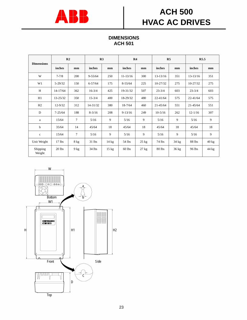
DIMENSIONSACH 501
DimensionsR2 R3 R4 R5 R5.5
inches mm inches mm inches mm inches mm inches mm
W 7-7/8 200 9-55/64 250 11-13/16 300 13-13/16 351 13-13/16 351
W1 5-29/32 150 6-57/64 175 8-55/64 225 10-27/32 275 10-27/32 275
H 14-17/64 362 16-3/4 425 19-31/32 507 23-3/4 603 23-3/4 603
H1 13-25/32 350 15-3/4 400 18-29/32 480 22-41/64 575 22-41/64 575
H2 12-9/32 312 14-31/32 380 18-7/64 460 21-45/64 551 21-45/64 551
D 7-25/64 188 8-3/16 208 9-13/16 249 10-5/16 262 12-1/16 307
a 15/64 7 5/16 9 5/16 9 5/16 9 5/16 9
b 35/64 14 45/64 18 45/64 18 45/64 18 45/64 18
c 15/64 7 5/16 9 5/16 9 5/16 9 5/16 9
Unit Weight 17 lbs 8 kg 31 lbs 14 kg 54 lbs 25 kg 74 lbs 34 kg 88 lbs 40 kg
Shipping Weight
20 lbs 9 kg 34 lbs 15 kg 60 lbs 27 kg 80 lbs 36 kg 96 lbs 44 kg
Front
Top
Side
C
D
a
H H2
bW1
W
H1
Bottom
ACH 500HVAC AC DRIVES
24
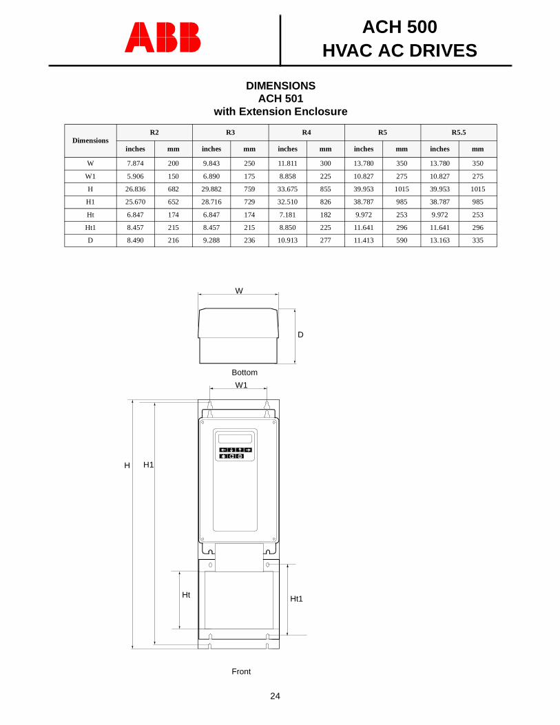
DIMENSIONSACH 501
with Extension Enclosure
DimensionsR2 R3 R4 R5 R5.5
inches mm inches mm inches mm inches mm inches mm
W 7.874 200 9.843 250 11.811 300 13.780 350 13.780 350
W1 5.906 150 6.890 175 8.858 225 10.827 275 10.827 275
H 26.836 682 29.882 759 33.675 855 39.953 1015 39.953 1015
H1 25.670 652 28.716 729 32.510 826 38.787 985 38.787 985
Ht 6.847 174 6.847 174 7.181 182 9.972 253 9.972 253
Ht1 8.457 215 8.457 215 8.850 225 11.641 296 11.641 296
D 8.490 216 9.288 236 10.913 277 11.413 590 13.163 335
D
H1
W1
W
Bottom
Front
H
Ht1Ht
ACH 500HVAC AC DRIVES
25
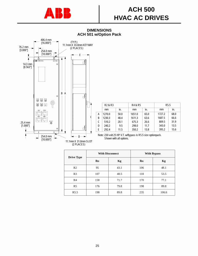
DIMENSIONSACH 501 w/Option Pack
Drive TypeWith Disconnect With Bypass
lbs Kg lbs Kg
R2 95 43.1 106 48.1
R3 107 48.5 118 53.5
R4 158 71.7 170 77.1
R5 176 79.8 198 89.8
R5.5 198 89.8 235 106.6
406.4 mm
254.0 mm76.2 mm
(TYP.)11.1mm X 33.0mm KEYWAY
(2 PLACES)
11.1mm X 31.0mm SLOT(2 PLACES)
254.0 mm
ABB Drives ACH 500
RESET
25.4 mm
14.3 mm
AB
C
D
E
ABCDE
1270.01230.3
510.2240.2292.4
50.048.420.1
9.511.5
1651.01611.3675.3298.0350.2
65.063.626.611.713.8
R2 & R3
mm in.
R4 & R5
mm in.SPM
AM2AM1
VM
[10.000"]
[1.000"]
[0.563"]
[10.000"]
[16.000"]
[3.000"]
1727.21687.5
809.5343.0395.2
68.066.631.913.515.6
R5.5
mm in.
Note: 230 volt 25 HP V.T. w/Bypass is R5.5 size optionpack.Shown with all options.
ACH 500HVAC AC DRIVES
26
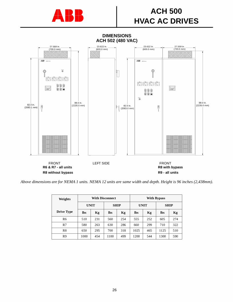
DIMENSIONSACH 502 (480 VAC)
Above dimensions are for NEMA 1 units. NEMA 12 units are same width and depth. Height is 96 inches (2,438mm).
Weights
Drive Type
With Disconnect With Bypass
UNIT SHIP UNIT SHIP
lbs Kg lbs Kg lbs Kg lbs Kg
R6 510 231 560 254 555 252 605 274
R7 580 263 630 286 660 299 710 322
R8 650 295 700 318 1025 465 1125 510
R9 1000 454 1100 499 1200 544 1300 590
88.0 in.(2235.0 mm)
FRONTLEFT SIDE
VM AM 1 AM 2 SP M
PO TSS1
OPL BPL FPL
RESET
ABB Dr ives
23.622 in.(600.0 mm)
23.622 in.(600.0 mm)
27.559 in.(700.0 mm)
82.0 in.(2083.0 mm)
SS 2
FRONT
VM AM1 AM 2 SPM
P OTSS1
OP L
SS2
B PL FPL
RESE T
ABB Drives
27.559 in.(700.0 mm)
82.0 in.(2083.1 mm)
88.0 in.(2235.0 mm)
R6 & R7 - all units
R8 without bypass
R8 with bypass
R9 - all units
ACH 500HVAC AC DRIVES
27
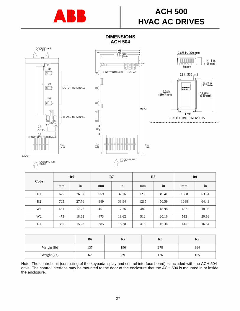
DIMENSIONSACH 504
Note: The control unit (consisting of the keypad/display and control interface board) is included with the ACH 504 drive. The control interface may be mounted to the door of the enclosure that the ACH 504 is mounted in or inside the enclosure.
CodeR6 R7 R8 R9
mm in mm in mm in mm in
H1 675 26.57 959 37.76 1255 49.41 1608 63.31
H2 705 27.76 989 38.94 1285 50.59 1638 64.49
W1 451 17.76 451 17.76 482 18.98 482 18.98
W2 473 18.62 473 18.62 512 20.16 512 20.16
D1 385 15.28 385 15.28 415 16.34 415 16.34
R6 R7 R8 R9
Weight (lb) 137 196 278 364
Weight (kg) 62 89 126 165
BRUDC+UDC-
D1
V2
W2
U2
PE
COOLING AIRINLET
COOLING AIR OUTLET
AIR
BACK
15.67 (398)16.85 (428)
W2W1
H2H1
PE
U1 V1 W1
AIRAIR
COOLING AIRINLET
LINE TERMINALS
MOTOR TERMINALS
BRAKE TERMINALS
GROUNDING TERMINALS
Front
14.27 in.
12.28 in.
5.9 in (150 mm)
7.875 in. (200 mm)
13.78 in.
Bottom
(489.7 mm) (350 mm)
(362 mm)
CONTROL UNIT DIMENSIONS
AAAAAAAAAAAAAAAAAAAAAAAAAAAAAAAAAAAAAAAAAAAAAAAAAAAA
AAAAAAAAAAAAAAAAAAAAAAAAAAAAAAAAAAAAAAAAAAAAAAA
4.13 in.(105 mm)
ABB Industrial Systems Inc.16250 W. Glendale DriveNew Berlin, WI 53151
Phone: (414) 785-3416Sales (800) 752-0696Fax: (414) 785-8525
Pro
duct
Bul
letin
AC
H50
0-0
2CE
ffec
tive
7/1/
95
Su
pers
edes
10/
1/9
3