abb drives - ortman electronics · ach 500 abb drives programming manual including application...
TRANSCRIPT
ACH 500
ABB Drives
Programming ManualIncluding Application Macros
ASEA BROWN BOVERI
$25.00 U.S.
ACH 500 Adjustable FrequencyAC Drives 2 to 400 HP, Series B
ACH 500-05CEFFECTIVE 11/1/94SUPERCEDES 6/1/94
1994 ABB Drives Inc. All Rights Reserved.
ACH 500 Adjustable FrequencyAC Drives 2 to 400 HP
Programming ManualIncluding Application Macros
ACH 500-05C
EFFECTIVE: 1994-11-01SUPERCEDES: 1994-06-01
ACH 500 Programming Manual iii
Safety Instructions
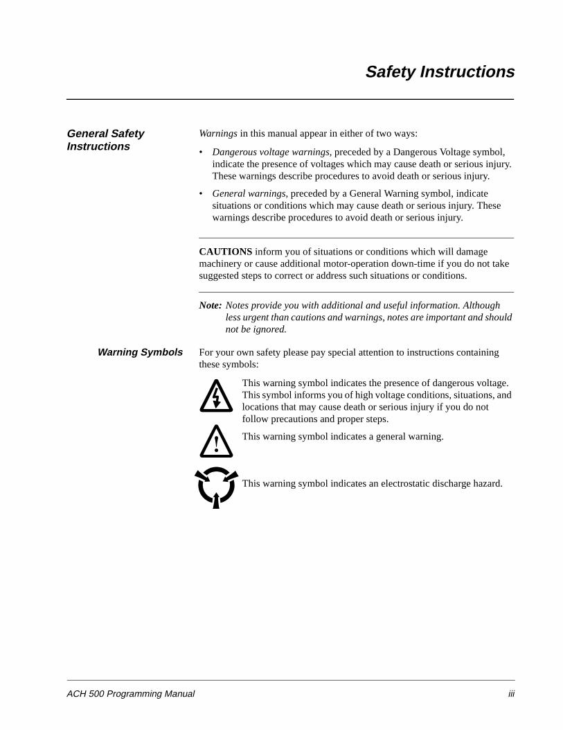
General Safety Instructions
Warnings in this manual appear in either of two ways:
• Dangerous voltage warnings, preceded by a Dangerous Voltage symbol, indicate the presence of voltages which may cause death or serious injury. These warnings describe procedures to avoid death or serious injury.
• General warnings, preceded by a General Warning symbol, indicate situations or conditions which may cause death or serious injury. These warnings describe procedures to avoid death or serious injury.
CAUTIONS inform you of situations or conditions which will damage machinery or cause additional motor-operation down-time if you do not take suggested steps to correct or address such situations or conditions.
Note: Notes provide you with additional and useful information. Although less urgent than cautions and warnings, notes are important and should not be ignored.
Warning Symbols For your own safety please pay special attention to instructions containing these symbols:
This warning symbol indicates the presence of dangerous voltage. This symbol informs you of high voltage conditions, situations, and locations that may cause death or serious injury if you do not follow precautions and proper steps.
This warning symbol indicates a general warning.
This warning symbol indicates an electrostatic discharge hazard.
Safety Instructions
iv ACH 500 Programming Manual
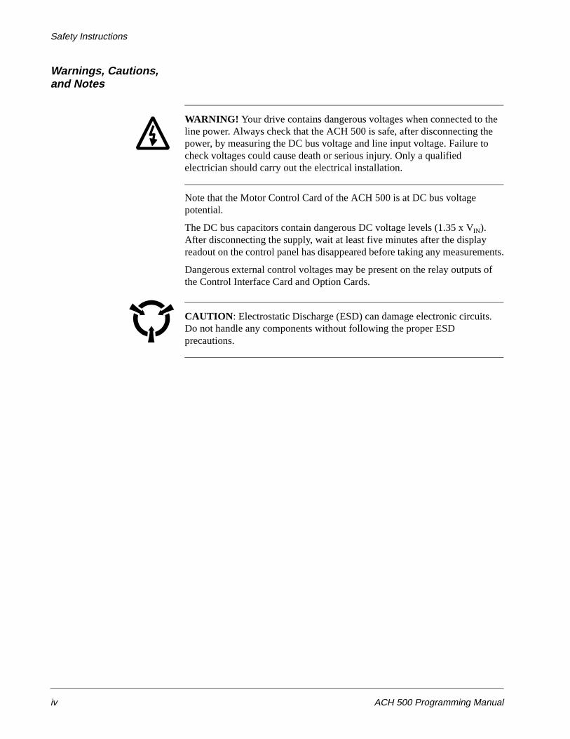
Warnings, Cautions,and Notes
WARNING! Your drive contains dangerous voltages when connected to the line power. Always check that the ACH 500 is safe, after disconnecting the power, by measuring the DC bus voltage and line input voltage. Failure to check voltages could cause death or serious injury. Only a qualified electrician should carry out the electrical installation.
Note that the Motor Control Card of the ACH 500 is at DC bus voltage potential.
The DC bus capacitors contain dangerous DC voltage levels (1.35 x VIN). After disconnecting the supply, wait at least five minutes after the display readout on the control panel has disappeared before taking any measurements.
Dangerous external control voltages may be present on the relay outputs of the Control Interface Card and Option Cards.
CAUTION: Electrostatic Discharge (ESD) can damage electronic circuits. Do not handle any components without following the proper ESD precautions.
ACH 500 Programming Manual v
Table of Contents
Chapter 1 – Introduction
How To Use This Manual . . . . . . . . . . . . . . . . . . . . . . . . . . . . . . . . . . . . . . . . . . . . . . . . . . . . . . . . . . 1-1Intended Audience . . . . . . . . . . . . . . . . . . . . . . . . . . . . . . . . . . . . . . . . . . . . . . . . . . . . . . . . . . . . . . . . 1-2Conventions Used In This Manual . . . . . . . . . . . . . . . . . . . . . . . . . . . . . . . . . . . . . . . . . . . . . . . . . . . 1-2
Control Panel Display . . . . . . . . . . . . . . . . . . . . . . . . . . . . . . . . . . . . . . . . . . . . . . . . . . . . . . . . . . 1-2Control Panel Keys . . . . . . . . . . . . . . . . . . . . . . . . . . . . . . . . . . . . . . . . . . . . . . . . . . . . . . . . . . . . 1-3
Related Publications . . . . . . . . . . . . . . . . . . . . . . . . . . . . . . . . . . . . . . . . . . . . . . . . . . . . . . . . . . . . . . 1-3
Chapter 2 – Overview of ACH 500 Programming
Overview of Application Macros . . . . . . . . . . . . . . . . . . . . . . . . . . . . . . . . . . . . . . . . . . . . . . . . . . . . 2-1Application Macros Defined . . . . . . . . . . . . . . . . . . . . . . . . . . . . . . . . . . . . . . . . . . . . . . . . . . . . . 2-1
Menu System of Parameters . . . . . . . . . . . . . . . . . . . . . . . . . . . . . . . . . . . . . . . . . . . . . . . . . . . . . . . . 2-2Start-up Data Parameters . . . . . . . . . . . . . . . . . . . . . . . . . . . . . . . . . . . . . . . . . . . . . . . . . . . . . . . . 2-2Operating Data Parameters . . . . . . . . . . . . . . . . . . . . . . . . . . . . . . . . . . . . . . . . . . . . . . . . . . . . . . 2-3Menu Navigation . . . . . . . . . . . . . . . . . . . . . . . . . . . . . . . . . . . . . . . . . . . . . . . . . . . . . . . . . . . . . . 2-3
Chapter 3 – Start-up Data
Start-up Data Parameters . . . . . . . . . . . . . . . . . . . . . . . . . . . . . . . . . . . . . . . . . . . . . . . . . . . . . . . . . . . 3-1Overview . . . . . . . . . . . . . . . . . . . . . . . . . . . . . . . . . . . . . . . . . . . . . . . . . . . . . . . . . . . . . . . . . . . . 3-1Parameter Selection . . . . . . . . . . . . . . . . . . . . . . . . . . . . . . . . . . . . . . . . . . . . . . . . . . . . . . . . . . . . 3-2
Chapter 4 – Control Operation
Operating Data Parameters . . . . . . . . . . . . . . . . . . . . . . . . . . . . . . . . . . . . . . . . . . . . . . . . . . . . . . . . . 4-1Overview . . . . . . . . . . . . . . . . . . . . . . . . . . . . . . . . . . . . . . . . . . . . . . . . . . . . . . . . . . . . . . . . . . . . 4-1Parameter Selection . . . . . . . . . . . . . . . . . . . . . . . . . . . . . . . . . . . . . . . . . . . . . . . . . . . . . . . . . . . . 4-3Motor Control Values . . . . . . . . . . . . . . . . . . . . . . . . . . . . . . . . . . . . . . . . . . . . . . . . . . . . . . . . . . 4-6
Keypad Control vs. External Control . . . . . . . . . . . . . . . . . . . . . . . . . . . . . . . . . . . . . . . . . . . . . . . . . 4-7Keypad Control . . . . . . . . . . . . . . . . . . . . . . . . . . . . . . . . . . . . . . . . . . . . . . . . . . . . . . . . . . . . . . . 4-7External Control . . . . . . . . . . . . . . . . . . . . . . . . . . . . . . . . . . . . . . . . . . . . . . . . . . . . . . . . . . . . . . . 4-7Keypad Reference 1 and Keypad PI . . . . . . . . . . . . . . . . . . . . . . . . . . . . . . . . . . . . . . . . . . . . . . . 4-9External Reference 1 and 2 . . . . . . . . . . . . . . . . . . . . . . . . . . . . . . . . . . . . . . . . . . . . . . . . . . . . . 4-10
Password Protection (Parameter Lock) . . . . . . . . . . . . . . . . . . . . . . . . . . . . . . . . . . . . . . . . . . . . . . 4-10
Chapter 5 – Standard Application Macro Programs
User Macro . . . . . . . . . . . . . . . . . . . . . . . . . . . . . . . . . . . . . . . . . . . . . . . . . . . . . . . . . . . . . . . . . . . . . 5-1Macro Applications and Access . . . . . . . . . . . . . . . . . . . . . . . . . . . . . . . . . . . . . . . . . . . . . . . . . . . . . 5-2Application 1 – HVAC . . . . . . . . . . . . . . . . . . . . . . . . . . . . . . . . . . . . . . . . . . . . . . . . . . . . . . . . . . . . 5-3
Operation Diagram . . . . . . . . . . . . . . . . . . . . . . . . . . . . . . . . . . . . . . . . . . . . . . . . . . . . . . . . . . . . . 5-3Input and Output Signals . . . . . . . . . . . . . . . . . . . . . . . . . . . . . . . . . . . . . . . . . . . . . . . . . . . . . . . . 5-3HVAC Macro External Connections . . . . . . . . . . . . . . . . . . . . . . . . . . . . . . . . . . . . . . . . . . . . . . . 5-4HVAC Parameter Settings . . . . . . . . . . . . . . . . . . . . . . . . . . . . . . . . . . . . . . . . . . . . . . . . . . . . . . . 5-5
Table of Contents
vi ACH 500 Programming Manual
Application 2 – Floating Point Control . . . . . . . . . . . . . . . . . . . . . . . . . . . . . . . . . . . . . . . . . . . . . . . . 5-6Operation Diagram . . . . . . . . . . . . . . . . . . . . . . . . . . . . . . . . . . . . . . . . . . . . . . . . . . . . . . . . . . . . . 5-6Input and Output Signals . . . . . . . . . . . . . . . . . . . . . . . . . . . . . . . . . . . . . . . . . . . . . . . . . . . . . . . . 5-6Floating Point Control External Connections . . . . . . . . . . . . . . . . . . . . . . . . . . . . . . . . . . . . . . . . . 5-7Floating Point Control Parameter Settings . . . . . . . . . . . . . . . . . . . . . . . . . . . . . . . . . . . . . . . . . . .5-8
Application 3 – HVAC-PI . . . . . . . . . . . . . . . . . . . . . . . . . . . . . . . . . . . . . . . . . . . . . . . . . . . . . . . . . 5-9Operation Diagram . . . . . . . . . . . . . . . . . . . . . . . . . . . . . . . . . . . . . . . . . . . . . . . . . . . . . . . . . . . . . 5-9Input and Output Signals . . . . . . . . . . . . . . . . . . . . . . . . . . . . . . . . . . . . . . . . . . . . . . . . . . . . . . . . 5-9HVAC-PI External Connections . . . . . . . . . . . . . . . . . . . . . . . . . . . . . . . . . . . . . . . . . . . . . . . . . . 5-10HVAC-PI Parameter Settings . . . . . . . . . . . . . . . . . . . . . . . . . . . . . . . . . . . . . . . . . . . . . . . . . . . . 5-11
Application 4 – Pump and Fan . . . . . . . . . . . . . . . . . . . . . . . . . . . . . . . . . . . . . . . . . . . . . . . . . . . . . . 5-12Operation Diagram . . . . . . . . . . . . . . . . . . . . . . . . . . . . . . . . . . . . . . . . . . . . . . . . . . . . . . . . . . . . 5-12Input and Output Signals . . . . . . . . . . . . . . . . . . . . . . . . . . . . . . . . . . . . . . . . . . . . . . . . . . . . . . . 5-12Pump and Fan External Connections . . . . . . . . . . . . . . . . . . . . . . . . . . . . . . . . . . . . . . . . . . . . . . 5-13Pump and Fan Parameter Settings . . . . . . . . . . . . . . . . . . . . . . . . . . . . . . . . . . . . . . . . . . . . . . . . 5-14
Chapter 6 – Parameters
ACH 500 Parameter Menus . . . . . . . . . . . . . . . . . . . . . . . . . . . . . . . . . . . . . . . . . . . . . . . . . . . . . . . . . 6-1ACH 500 Parameters . . . . . . . . . . . . . . . . . . . . . . . . . . . . . . . . . . . . . . . . . . . . . . . . . . . . . . . . . . . . . . 6-1Main 10 Control Connections . . . . . . . . . . . . . . . . . . . . . . . . . . . . . . . . . . . . . . . . . . . . . . . . . . . . . . . 6-2
Group 10.1 Start/Stop/Direction . . . . . . . . . . . . . . . . . . . . . . . . . . . . . . . . . . . . . . . . . . . . . . . . . . . 6-2Group 10.2 Ext Reference Select . . . . . . . . . . . . . . . . . . . . . . . . . . . . . . . . . . . . . . . . . . . . . . . . . . 6-4Group 10.3 Preset Speeds . . . . . . . . . . . . . . . . . . . . . . . . . . . . . . . . . . . . . . . . . . . . . . . . . . . . . . . . 6-7Group 10.4 System Contr Inputs . . . . . . . . . . . . . . . . . . . . . . . . . . . . . . . . . . . . . . . . . . . . . . . . . . 6-9Group 10.5 Analog Inputs . . . . . . . . . . . . . . . . . . . . . . . . . . . . . . . . . . . . . . . . . . . . . . . . . . . . . . 6-10Group 10.6 Relay Outputs . . . . . . . . . . . . . . . . . . . . . . . . . . . . . . . . . . . . . . . . . . . . . . . . . . . . . . 6-12Group 10.7 Analog Outputs . . . . . . . . . . . . . . . . . . . . . . . . . . . . . . . . . . . . . . . . . . . . . . . . . . . . . 6-14Group 10.8 Ext Communication . . . . . . . . . . . . . . . . . . . . . . . . . . . . . . . . . . . . . . . . . . . . . . . . . . 6-16
Main 20 Drive Parameters . . . . . . . . . . . . . . . . . . . . . . . . . . . . . . . . . . . . . . . . . . . . . . . . . . . . . . . . . 6-16Group 20.2 Start/Stop . . . . . . . . . . . . . . . . . . . . . . . . . . . . . . . . . . . . . . . . . . . . . . . . . . . . . . . . . . 6-17Group 20.3 Accel/Decel . . . . . . . . . . . . . . . . . . . . . . . . . . . . . . . . . . . . . . . . . . . . . . . . . . . . . . . . 6-20Group 20.4 Motor Control . . . . . . . . . . . . . . . . . . . . . . . . . . . . . . . . . . . . . . . . . . . . . . . . . . . . . . 6-22Group 20.5 Crit Frequencies . . . . . . . . . . . . . . . . . . . . . . . . . . . . . . . . . . . . . . . . . . . . . . . . . . . . . 6-28
Main 30 Protection Parameters . . . . . . . . . . . . . . . . . . . . . . . . . . . . . . . . . . . . . . . . . . . . . . . . . . . . . 6-30Group 30.1 Fault Function . . . . . . . . . . . . . . . . . . . . . . . . . . . . . . . . . . . . . . . . . . . . . . . . . . . . . . 6-30Group 30.2 Automatic Reset . . . . . . . . . . . . . . . . . . . . . . . . . . . . . . . . . . . . . . . . . . . . . . . . . . . . 6-37Group 30.3 Supervision . . . . . . . . . . . . . . . . . . . . . . . . . . . . . . . . . . . . . . . . . . . . . . . . . . . . . . . . 6-38Group 30.4 Information . . . . . . . . . . . . . . . . . . . . . . . . . . . . . . . . . . . . . . . . . . . . . . . . . . . . . . . . 6-40
Main 40 Application Parameters . . . . . . . . . . . . . . . . . . . . . . . . . . . . . . . . . . . . . . . . . . . . . . . . . . . . 6-41Group 40.1 PI-Controller . . . . . . . . . . . . . . . . . . . . . . . . . . . . . . . . . . . . . . . . . . . . . . . . . . . . . . . 6-41Group 40.2 Pump & Fan Control . . . . . . . . . . . . . . . . . . . . . . . . . . . . . . . . . . . . . . . . . . . . . . . . . 6-45
Appendix A – Complete Parameter Settings . . . . . . . . . . . . . . . . . . . . . . . . . . . . . . . . . . . . .A-1
Appendix B – Programming Digital Inputs . . . . . . . . . . . . . . . . . . . . . . . . . . . . . . . . . . . . . .B-1
Index . . . . . . . . . . . . . . . . . . . . . . . . . . . . . . . . . . . . . . . . . . . . . . . . . . . . . . . . . . . . . . . . . . . . . I-1
ACH 500 Programming Manual 1-1
Chapter 1 – Introduction
This chapter describes the purpose and contents of this manual, describes the intended audience, explains conventions used in this manual, and lists related publications.
How To Use This Manual
The purpose of this manual is to provide you with the information necessary to select, modify, and apply Application macros to the operation of your ACH 500 drive.
ACH 500 user documentation also includes either the ACH 501 Installation & Start-up Manual or the ACH 502 Installation & Start-up Manual, which is included with the drive.
Chapter 1 – Introduction, the chapter you are reading now, introduces you to the ACH 500 Adjustable Frequency AC Drives Programming Manual Including Application Macros and conventions used throughout the manual.
Chapter 2 – Overview of ACH 500 Programming provides an overview of Application macros and describes how to use the menu system of parameters to select and modify the macros.
Chapter 3 – Start-up Data lists and explains the Start-up Data parameters. This chapter also describes how to set the Start-up Data parameters.
Chapter 4 – Control Operation describes Operating Data parameters, keypad references, drive-mounted and external controls, setting parameters for your specific drive application, and protecting your drive parameters from unauthorized changes.
Chapter 5 – Standard Application Macro Programs defines Application macros in terms of parameter settings. This chapter also describes the operation and application suitability of four standard Application macros and the User macro.
Chapter 6 – Parameters lists the ACH 500 parameters and explains the functions of each parameters.
Appendix A – Complete Parameter Settings lists, in a table form, all parameter settings for the ACH 500.
Appendix B – Programming Digital Inputs lists, in table form, parameter values and digital I/O configurations.
Index helps you locate the page numbers of topics contained in this manual.
Chapter 1 – Introduction
1-2 ACH 500 Programming Manual
Intended Audience The audience for this manual has:
• Knowledge of standard electrical wiring practices, electronic components, and electrical schematic symbols.
• Minimal knowledge of ABB product names and terminology.
• No experience or training in installing, operating, or servicing the ACH 500.
Conventions Used In This Manual
The following are illustrations and examples of Control Panel keys and Control Panel display formats.
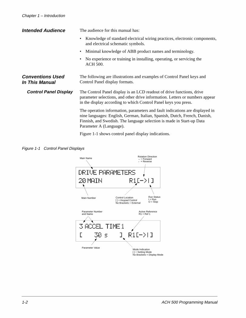
Control Panel Display The Control Panel display is an LCD readout of drive functions, drive parameter selections, and other drive information. Letters or numbers appear in the display according to which Control Panel keys you press.
The operation information, parameters and fault indications are displayed in nine languages: English, German, Italian, Spanish, Dutch, French, Danish, Finnish, and Swedish. The language selection is made in Start-up Data Parameter A (Language).
Figure 1-1 shows control panel display indications.
Figure 1-1 Control Panel Displays
Main NameRotation Direction→ = Forward← = Reverse
Main Number Control Location[ ] = Keypad ControlNo Brackets = External
Run StatusI = RunO = Stop
Parameter Numberand Name
Active ReferenceR1 = Ref 1
Parameter ValueMode Indication[ ] = Setting ModeNo Brackets = Display Mode
Chapter 1 – Introduction
ACH 500 Programming Manual 1-3
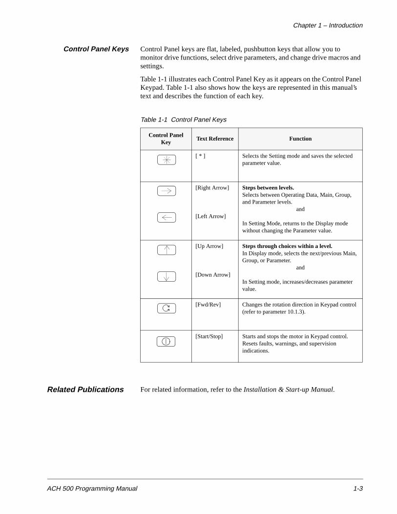
Control Panel Keys Control Panel keys are flat, labeled, pushbutton keys that allow you to monitor drive functions, select drive parameters, and change drive macros and settings.
Table 1-1 illustrates each Control Panel Key as it appears on the Control Panel Keypad. Table 1-1 also shows how the keys are represented in this manual’s text and describes the function of each key.
Table 1-1 Control Panel Keys
Related Publications For related information, refer to the Installation & Start-up Manual.
Control Panel Key
Text Reference Function
[ * ] Selects the Setting mode and saves the selected parameter value.
[Right Arrow]
[Left Arrow]
Steps between levels.Selects between Operating Data, Main, Group, and Parameter levels.
and
In Setting Mode, returns to the Display mode without changing the Parameter value.
[Up Arrow]
[Down Arrow]
Steps through choices within a level.In Display mode, selects the next/previous Main, Group, or Parameter.
and
In Setting mode, increases/decreases parameter value.
[Fwd/Rev] Changes the rotation direction in Keypad control (refer to parameter 10.1.3).
[Start/Stop] Starts and stops the motor in Keypad control. Resets faults, warnings, and supervision indications.

Chapter 1 – Introduction
1-4 ACH 500 Programming Manual
This page intentionally left blank.
ACH 500 Programming Manual 2-1
Chapter 2 – Overview of ACH 500 Programming
This chapter defines Application macros in terms of parameter settings and describes how to use the menu system of parameters to select and modify the macros.
Overview of ApplicationMacros
Application MacrosDefined
Application macros are pre-programmed parameter sets. You’ll use them to start the ACH 500 quickly and easily.
Application macros minimize the number of different parameters to be set during start-up. All parameters have factory-set default values. The HVAC macro program is the factory-set default macro.
While starting up the ACH 500, you can specify a macro as the base setting for a drive. You can select any one of the following macros from Start-up Data Parameter B (Applications):
• HVAC
• FLOAT PT.
• HVAC – PI
• Pump and Fan
In addition to these application macros, there is a User macro. The User macro allows the user to save the existing parameter settings for recall at a later time.
Macro programs do not usually set all parameter values exactly as needed for a special application. Check frequency limits and acceleration/deceleration times and modify as required for your application.
You may need to modify digital and analog inputs and/or outputs. The Parameter Settings tables in Chapter 5 – Standard Application Macro Programs indicate parameters you may have to modify. These parameters are indicated in the tables with an arrow (→) symbol.

Chapter 2 – Overview of ACH 500 Programming
2-2 ACH 500 Programming Manual
Menu System of Parameters
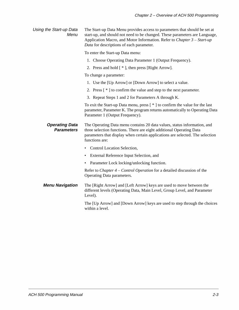
The parameters in the ACH 500 are organized via a system of menus. There are four levels of information, plus a start-up data menu. The four levels are: Operating Data, Main Level, Group Level, and Parameter Level. Each is described in this chapter.
Figure 2-1 shows how to select Start-up Data parameters, Operating Data parameters, Application macros, Main, Group, and Parameter levels using the Control Panel keypad.
Figure 2-1 Parameter Selection
Start-up DataParameters
The Start-up Data menu contains some basic settings needed to match the ACH 500 with your motor and to set the Control Panel display language. This menu also contains a list of pre-programmed Application macros. The Start-up Data menu is the first menu you modify to start-up your drive.
40.2 PUMP & FAN CONTROL
40.1 PI-CONTROL
30.4 INFORMATION
30.3 SUPERVISION
30.2 AUTOMATIC RESET
30.1 FAULT FUNCTION
20.5 CRITICAL FREQUENCIES
20.4 MOTOR CONTROL
20.3 ACCEL/DECEL
20.2 START/STOP
20.1 FREQ/CURRENT LIMITS
10.8 EXT COMMUNICATION
10.7 ANALOG OUTPUTS
10.6 RELAY OUTPUTS
10.5 ANALOG INPUTS
START-UP DATA
C APPLIC. RESTORED Supply Voltage
20 PARAMETER LOCK....
30 PROTECTION PARAMETERS
10 CONTROL CONNECTIONS
10.4 SYSTEM CONTR INPUTS
10.3 PRESET SPEEDS
10.2 EX REFERENCE SELECT
10.1 START/STOP/ DIRECTION
20.3.8 DECEL REF2 TIME
20.3.7 ACCEL REF2 TIME
20.3.6 DECEL TIME 2
20.3.5 ACCEL TIME 2
20.3.4 DECEL TIME 1
20.3.3 ACCEL TIME 1
20.3.2 ACC/DEC RAMP SHAPE
20.3.1 ACC/DEC 1 OR 2 SEL
OPERATING DATA MAIN LEVEL GROUP LEVEL
PARAMETER LEVEL
1 OUTPUT FREQ.2 MOTOR SPEED
PARAMETERS20 DRIVE
A LANGUAGEAPPLICATION
1 HVAC
MACROS
2 FLOAT PT.3 HVAC – PI4 P&F AUTOM..
B APPLICATION
.
.
. ....
40 APPLICATION PARAMETERS
Chapter 2 – Overview of ACH 500 Programming
ACH 500 Programming Manual 2-3
Using the Start-up DataMenu
The Start-up Data Menu provides access to parameters that should be set at start-up, and should not need to be changed. These parameters are Language, Application Macro, and Motor Information. Refer to Chapter 3 – Start-up Data for descriptions of each parameter.
To enter the Start-up Data menu:
1. Choose Operating Data Parameter 1 (Output Frequency).
2. Press and hold [ * ], then press [Right Arrow].
To change a parameter:
1. Use the [Up Arrow] or [Down Arrow] to select a value.
2. Press [ * ] to confirm the value and step to the next parameter.
3. Repeat Steps 1 and 2 for Parameters A through K.
To exit the Start-up Data menu, press [ * ] to confirm the value for the last parameter, Parameter K. The program returns automatically to Operating Data Parameter 1 (Output Frequency).
Operating DataParameters
The Operating Data menu contains 20 data values, status information, and three selection functions. There are eight additional Operating Data parameters that display when certain applications are selected. The selection functions are:
• Control Location Selection,
• External Reference Input Selection, and
• Parameter Lock locking/unlocking function.
Refer to Chapter 4 – Control Operation for a detailed discussion of the Operating Data parameters.
Menu Navigation The [Right Arrow] and [Left Arrow] keys are used to move between the different levels (Operating Data, Main Level, Group Level, and Parameter Level).
The [Up Arrow] and [Down Arrow] keys are used to step through the choices within a level.
Chapter 2 – Overview of ACH 500 Programming
2-4 ACH 500 Programming Manual
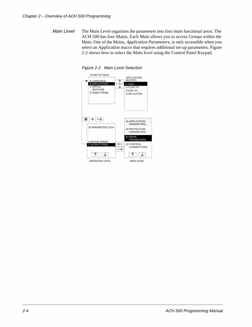
Main Level The Main Level organizes the parameters into four main functional areas. The ACH 500 has four Mains. Each Main allows you to access Groups within the Main. One of the Mains, Application Parameters, is only accessible when you select an Application macro that requires additional set-up parameters. Figure 2-2 shows how to select the Main level using the Control Panel Keypad.
Figure 2-2 Main Level Selection
START-UP DATA
C APPLIC. RESTORED Supply Voltage
20 PARAMETER LOCK....
30 PROTECTION PARAMETERS
10 CONTROL CONNECTIONS
OPERATING DATA MAIN LEVEL
1 OUTPUT FREQ.2 MOTOR SPEED
PARAMETERS20 DRIVE
A LANGUAGEAPPLICATION
1 HVAC
MACROS
2 FLOAT PT.3 HVAC-PI4 P&F AUTOM..
B APPLICATION
.
.
. ....
40 APPLICATION PARAMETERS
Chapter 2 – Overview of ACH 500 Programming
ACH 500 Programming Manual 2-5
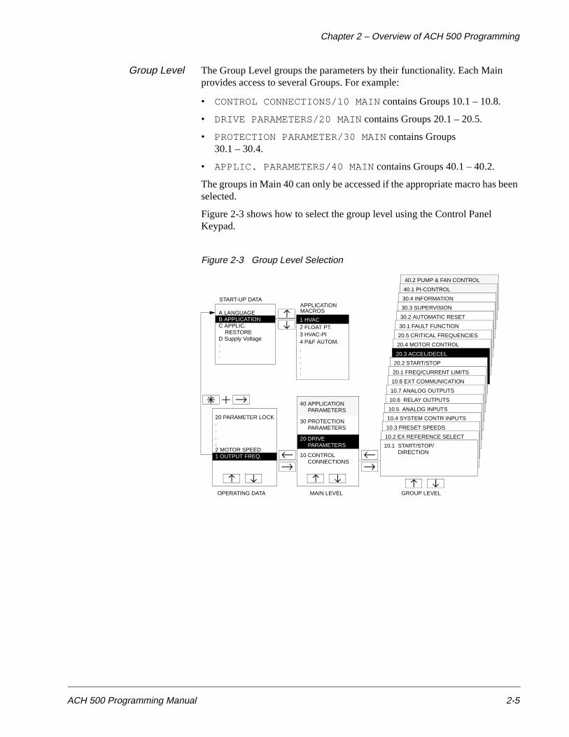
Group Level The Group Level groups the parameters by their functionality. Each Main provides access to several Groups. For example:
• CONTROL CONNECTIONS/10 MAIN contains Groups 10.1 – 10.8.
• DRIVE PARAMETERS/20 MAIN contains Groups 20.1 – 20.5.
• PROTECTION PARAMETER/30 MAIN contains Groups 30.1 – 30.4.
• APPLIC. PARAMETERS/40 MAIN contains Groups 40.1 – 40.2.
The groups in Main 40 can only be accessed if the appropriate macro has been selected.
Figure 2-3 shows how to select the group level using the Control Panel Keypad.
Figure 2-3 Group Level Selection
40.2 PUMP & FAN CONTROL
40.1 PI-CONTROL
30.4 INFORMATION
30.3 SUPERVISION
30.2 AUTOMATIC RESET
30.1 FAULT FUNCTION
20.5 CRITICAL FREQUENCIES
20.4 MOTOR CONTROL
20.3 ACCEL/DECEL
20.2 START/STOP
20.1 FREQ/CURRENT LIMITS
10.8 EXT COMMUNICATION
10.7 ANALOG OUTPUTS
10.6 RELAY OUTPUTS
10.5 ANALOG INPUTS
START-UP DATA
C APPLIC. RESTORED Supply Voltage
20 PARAMETER LOCK....
30 PROTECTION PARAMETERS
10 CONTROL CONNECTIONS
10.4 SYSTEM CONTR INPUTS
10.3 PRESET SPEEDS
10.2 EX REFERENCE SELECT
10.1 START/STOP/ DIRECTION
OPERATING DATA MAIN LEVEL GROUP LEVEL
1 OUTPUT FREQ.2 MOTOR SPEED
PARAMETERS20 DRIVE
A LANGUAGEAPPLICATION
1 HVAC
MACROS
2 FLOAT PT.3 HVAC-PI4 P&F AUTOM..
B APPLICATION
.
.
. ....
40 APPLICATION PARAMETERS
Chapter 2 – Overview of ACH 500 Programming
2-6 ACH 500 Programming Manual
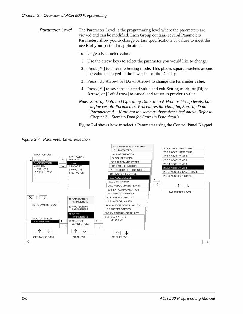
Parameter Level The Parameter Level is the programming level where the parameters are viewed and can be modified. Each Group contains several Parameters. Parameters allow you to change certain specifications or values to meet the needs of your particular application.
To change a Parameter value:
1. Use the arrow keys to select the parameter you would like to change.
2. Press [ * ] to enter the Setting mode. This places square brackets around the value displayed in the lower left of the Display.
3. Press [Up Arrow] or [Down Arrow] to change the Parameter value.
4. Press [ * ] to save the selected value and exit Setting mode, or [Right Arrow] or [Left Arrow] to cancel and return to previous value.
Note: Start-up Data and Operating Data are not Main or Group levels, but define certain Parameters. Procedures for changing Start-up Data Parameters A – K are not the same as those described above. Refer to Chapter 3 – Start-up Data for Start-up Data details.
Figure 2-4 shows how to select a Parameter using the Control Panel Keypad.
Figure 2-4 Parameter Level Selection
40.2 PUMP & FAN CONTROL
40.1 PI-CONTROL
30.4 INFORMATION
30.3 SUPERVISION
30.2 AUTOMATIC RESET
30.1 FAULT FUNCTION
20.5 CRITICAL FREQUENCIES
20.4 MOTOR CONTROL
20.3 ACCEL/DECEL
20.2 START/STOP
20.1 FREQ/CURRENT LIMITS
10.8 EXT COMMUNICATION
10.7 ANALOG OUTPUTS
10.6 RELAY OUTPUTS
10.5 ANALOG INPUTS
START-UP DATA
C APPLIC. RESTORED Supply Voltage
20 PARAMETER LOCK....
30 PROTECTION PARAMETERS
10 CONTROL CONNECTIONS
10.4 SYSTEM CONTR INPUTS
10.3 PRESET SPEEDS
10.2 EX REFERENCE SELECT
10.1 START/STOP/ DIRECTION
20.3.8 DECEL REF2 TIME
20.3.7 ACCEL REF2 TIME
20.3.6 DECEL TIME 2
20.3.5 ACCEL TIME 2
20.3.4 DECEL TIME 1
20.3.3 ACCEL TIME 1
20.3.2 ACC/DEC RAMP SHAPE
20.3.1 ACC/DEC 1 OR 2 SEL
OPERATING DATA MAIN LEVEL GROUP LEVEL
PARAMETER LEVEL
1 OUTPUT FREQ.2 MOTOR SPEED
PARAMETERS20 DRIVE
A LANGUAGEAPPLICATION
1 HVAC
MACROS
2 FLOAT PT.3 HVAC – PI4 P&F AUTOM..
B APPLICATION
.
.
. ....
40 APPLICATION PARAMETERS
Chapter 2 – Overview of ACH 500 Programming
ACH 500 Programming Manual 2-7
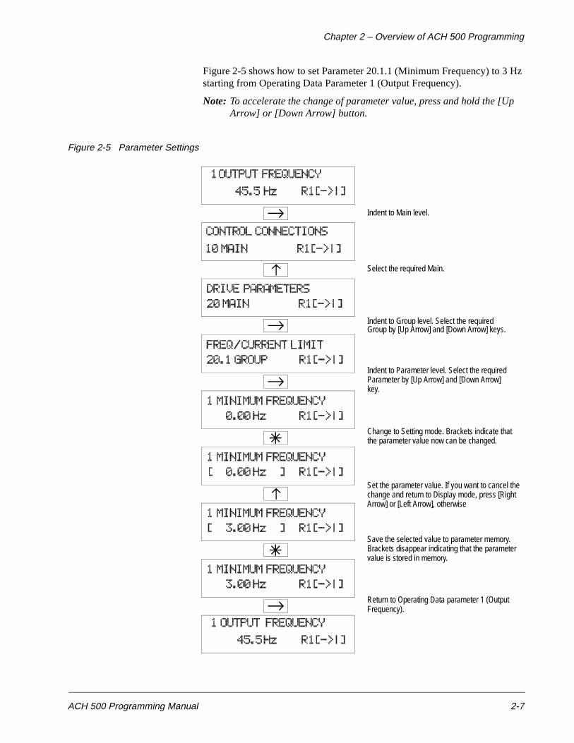
Figure 2-5 shows how to set Parameter 20.1.1 (Minimum Frequency) to 3 Hz starting from Operating Data Parameter 1 (Output Frequency).
Note: To accelerate the change of parameter value, press and hold the [Up Arrow] or [Down Arrow] button.
Figure 2-5 Parameter Settings
Indent to Main level.
Select the required Main.
Indent to Group level. Select the required
Indent to Parameter level. Select the requiredParameter by [Up Arrow] and [Down Arrow]key.
Change to Setting mode. Brackets indicate thatthe parameter value now can be changed.
Set the parameter value. If you want to cancel thechange and return to Display mode, press [RightArrow] or [Left Arrow], otherwise
Save the selected value to parameter memory.Brackets disappear indicating that the parametervalue is stored in memory.
Return to Operating Data parameter 1 (OutputFrequency).
Group by [Up Arrow] and [Down Arrow] keys.
Chapter 2 – Overview of ACH 500 Programming
2-8 ACH 500 Programming Manual
Application Macros Table 2-1 is an example of HVAC macro parameters that you are most likely to modify if you are using the ACH 500 HVAC macro to control your motor. The HVAC macro default settings appear in the Default column.
Table 2-1 HVAC Macro Parameters
Refer to Chapter 5 – Standard Application Macro Programs for a detailed discussion of the Application macros.
Main Group Parameter Default
OPERATING DATA
OPERATING DATA
9 CONTROL LOCATION KEYPAD R1
12 EXT REF 1 OR 2 REF 1
20 PARAMETER LOCK OPEN xxx
START-UP DATA
START-UP DATA
A LANGUAGE ENGLISH
B APPLICATIONS HVAC
C APPLIC. RESTORE NO
D SUPPLY VOLTAGE 480/230/380
E USER DISPLAY SCALE 0
F MOTOR CURRENT -FLA (Current Rating)
G MOTOR POWER (Power Rating)
H MOTOR POWER FACTOR 0.83
10 CONTROL CONNECTIONS
10.1 START/STOP/DIRECTION
10.1.3 LOC/EXT DIRECTION
FORWARD
10.3 PRESET SPEEDS
10.3.2 PRESET SPEED 1 5 Hz
10.3.3 PRESET SPEED 2 10 Hz
10.3.4 PRESET SPEED 3 15 Hz
10.5 ANALOG INPUTS
10.5.1 MINIMUM AI1 0 V/0 mA
10.5.2 MAXIMUM AI1 10 V/20 mA
10.7 ANALOG OUTPUTS
10.7.3 MINIMUM AO1 0 mA
10.7.8 MINIMUM AO2 0 mA
20DRIVE PARAMETERS
20.1 FREQ /CURRENTLIMITS
20.1.1 MINIMUM FREQUENCY
0 Hz
20.1.2 MAXIMUM FREQUENCY
60 Hz
20.1.4 CURRENT LIMIT (1.5 x IN) A
20.3 ACCEL/DECEL
20.3.3 ACCEL TIME 1 3s
20.3.4 DECEL TIME 1 3s
ACH 500 Programming Manual 3-1
Chapter 3 – Start-up Data
This chapter lists and explains the Start-up Data parameters and describes how to set these parameters. The Start-up Data parameters are a special set of parameters that allow you to set-up the drive and motor information.
Start-up Data parameters should only need to be set during start-up and should not need to be changed.
Start-up Data Parameters
Overview To access the Start-up Data parameters, you must be at Operating Data Parameter 1 (Output Frequency). Press and Hold the [ * ] key while pressing the [Right Arrow] key. This will bring you to Start-up Data Parameter A (Language).
The [Up Arrow] and [Down Arrow] keys are used to change the value or selection for the Start-up Data parameters. When a parameter is set to the value or selection you want, press the [ * ] key to enter that value as the acceptable value and move to the next parameter.
To complete the Start-up Data parameters and return to the Operating Data parameters, continue to enter the information by pressing [ * ] for each Start-up Data parameter.
The Range/Unit column in Table 3-1 shows parameter values. The text following the table explains parameter values in detail.
Chapter 3 – Start-up Data
3-2 ACH 500 Programming Manual
Table 3-1 Start-up Data Parameters
Parameter Selection The following is a list of the Start-up Data parameters with a description of each parameter.
A LANGUAGE The ACH 500 displays all information in the language you select. The available languages are: English, German, Italian, Spanish, Dutch, French, Danish, Finnish, and Swedish.
B APPLICATIONS This parameter is used to select the Application macro which will configure the ACH 500 for a particular application. Refer to Chapter 6 – Parameters for a list of available Application macros.
C APPLIC. RESTORE This parameter restores all parameters of the current application to the original parameter values for that macro.
D SUPPLY VOLTAGE This parameter is used to set the supply voltage to the ACH 500. The choices are 440, 460, 480, and 500 VAC for 480-volt units or 208, 220, 230, and 240 VAC for 230-volt units.
E USER DISPLAYSCALE
This parameter is used to set the scaling factor for Operating Data Parameter 2 (Speed). When set to 0, the speed display will show RPM. When set to 100, the speed display will show %. When set to any other value from 0 – 10000, the display will show this value (minus slip unless slip compensation is ON) when the output frequency is at the frequency set by Start-up Data Parameter I (Motor Base Frequency).
Parameter Range/Unit Description
A LANGUAGE Available languages Language selection.
B APPLICATIONS Application macros Application macro selection.
C APPLIC. RESTORE No, Yes Restores parameters to original values.
D SUPPLY VOLTAGE Supply voltage selections
Sets the supply voltage.
E USER DISPLAY SCALE
0 – 10000 Scaling factor for speed.
F MOTOR CURRENT -FLA
0 A – 1000 A Matches the ACH 500 to the rated motor current.
G MOTOR POWER hp (kW)
0.7 HP – 1340 HP (0.5 kW – 1000 kW)
Matches the motor rated power.
H MOTOR POWER FACTOR
0.1 – 1.0 Matches the motor power factor.
I MOTOR BASE FREQ. 30 Hz – 500 Hz Sets the motor frequency.
J MOTOR BASE R.P.M. 200 rpm – sync. speed
Sets the nameplate speed.
K MOTOR NOM. VOLTAGE
110 V – 575 V Sets the motor nameplate voltage.
Chapter 3 – Start-up Data
ACH 500 Programming Manual 3-3
F MOTOR CURRENT-FLA
This parameter matches the ACH 500 to the rated motor current, adjustable between 0 and 1000 amps. The drive uses this parameter for motor overload protection and current (amperage) information displays.
If the accuracy of the current display (parameter O.3) is off by more than 10% due to long motor cables (ACS 501 units only), a software calculation can be installed by pressing and holding the [left arrow] until an exclamation point appears on the display. This will calculate the current based on the motor power and power factor. These parameters must be entered correctly for the calculation to be accurate.
G MOTOR POWER This parameter matches the motor rated power, adjustable between 0.7 hp and 1340 hp. The drive uses this parameter for motor overload and kWh information displays. The left key switches the display between hp and kWh. To change the display, press and hold the left key for two seconds.
H MOTOR POWERFACTOR
This parameter matches the motor power factor (at rated speed and load on sinusoidal power), adjustable between 0.10 and 1.0. The drive uses this parameter for motor torque and power information displays.
I MOTOR BASEFREQUENCY
This parameter is used to set the designed frequency of the motor, adjustable from 30 Hz to 500 Hz in 10 Hz increments. Changing this value will automatically set the Field Weakening Point (FWP) to the same value.
J MOTOR BASE R.P.M. This parameter is used to set the nameplate speed of the motor and is adjustable from 200 to the maximum 2 pole motor speed based on Start-up Data Parameter I (Motor Base Frequency).
K MOTOR NOM.VOLTAGE
This parameter is used to set the motor nameplate voltage. The default is 460 V for 480-volt units and 230 V for 230-volt units. Changing this parameter automatically changes the Maximum Output Voltage.
Note: If the motor rated voltage is lower than the supply voltage, make sure that the motor insulation is rated for the DC bus voltage level which is VIN × 110% × 1.35 × 1.3 minimum (input voltage × ±10% tolerance × peak of rectified wave × overvoltage limit).
Chapter 3 – Start-up Data
3-4 ACH 500 Programming Manual
This page intentionally left blank.
ACH 500 Programming Manual 4-1
Chapter 4 – Control Operation
This chapter describes the Operating Data parameters and how to monitor and select them. It explains Keypad control and External control, and describes the Keypad Reference 1, Keypad PI, and External Reference 1 and 2 parameters.
Operating Data Parameters
The Operating Data Parameter monitored values are updated five times a second.
Parameters 1 – 8 monitor drive functions and do not affect drive performance.
Overview To monitor drive and motor activity, select Operating Data Parameters 1 – 8. These parameters display information about the ACH 500 and motor activity only. You cannot change the values of these parameters. Refer to Motor Control Values in this chapter for more information on the monitoring functions of Operating Data Parameters 1 – 8.
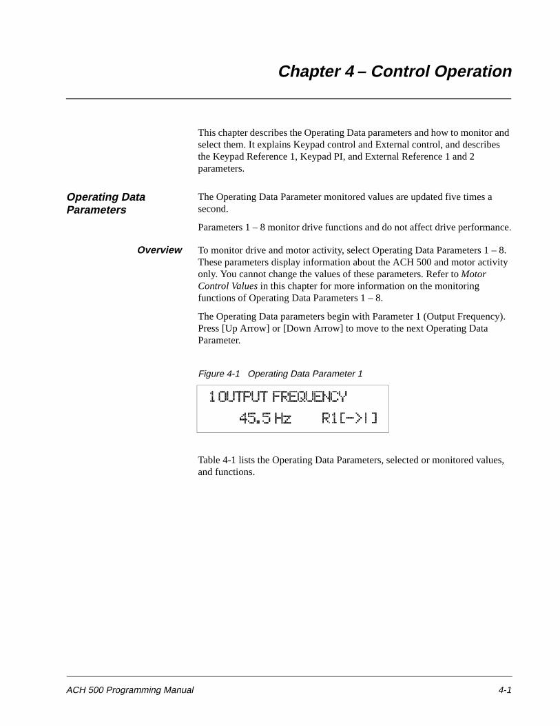
The Operating Data parameters begin with Parameter 1 (Output Frequency). Press [Up Arrow] or [Down Arrow] to move to the next Operating Data Parameter.
Figure 4-1 Operating Data Parameter 1
Table 4-1 lists the Operating Data Parameters, selected or monitored values, and functions.
Chapter 4 – Control Operation
4-2 ACH 500 Programming Manual
Table 4-1 Operating Data Parameters
Parameter Range/Unit Description
1 OUTPUT FREQUENCY Hz Frequency to motor.
2 SPEED rpm/%/no units Calculated speed, either motor RPM, %, or a scaled speed display. Displayed value is based on frequency minus slip.
3 MOTOR CURRENT A Motor current, (10% accuracy).
4 % RATED TORQUE % Calculated motor torque. 100 is the motor nominal torque rating, (15% accuracy).
5 % RATED POWER % Calculated motor power. 100 is the motor nominal power rating, (15% accuracy).
6 DC BUS VOLTAGE V / % Intermediate circuit DC voltage displayed in VDC and % of full voltage.
7 OUTPUT VOLTAGE V Calculated motor voltage, (5% accuracy).
8 DRIVE TEMPERATURE degrees C and F Temperature of the heatsink.
9 CONTROL LOCATION KEYPAD R1/KEYPAD PI/ EXTERNAL
Control location selection (R1 = Referenced, PI = Closed loop controller).
10 KEYPAD REF 1 Hz Frequency reference from Control Panel.
11 KEYPAD PI (REF 2) % Frequency reference (controller reference for PI) from Control Panel.
12 EXT REF 1 OR 2 REF1/REF2 External control place selection.
13 EXTERNAL REF 1 Hz External frequency reference.
14 EXTERNAL REF 2 % External controller reference.
15 RUN TIME h/min Elapsed time meter.
16 KILOWATT HOURS kWh kWh meter.
17 LAST-RECD FAULT – The latest fault and warning indication.
18 SECOND-RECD FAULT – The previous fault and warning indication.
19 FIRST-RECD FAULT – The oldest fault and warning indication.
20 PARAMETER LOCK OPEN xxx/LOCKED xxx OPEN/LOCKED
Parameter software lock (xxx = 358 to unlock). Lock from Digital Inputs.
Chapter 4 – Control Operation
ACH 500 Programming Manual 4-3
*) Visible only when PI-Control macro or P&F Autom. macro is selected.**) Visible only when P&F Autom. macro is selected.
You may change the values of some parameters to fit the needs of your application. For example, to control the ACH 500 from the keypad rather than the HOA switch and speed pot or external devices:
1. Press [Left Arrow] or [Right Arrow] until the LCD Display displays any one of the Operating Data Parameters listed in Table 4-1.
2. Press [Up Arrow] or [Down Arrow] until 9 CONTROL LOCATION displays. EXTERNAL displays on the second line of the LCD Display.
3. Press [ * ] to enter the Parameter Setting mode. This displays square brackets [ ] around the EXTERNAL display.
4. Press [Up Arrow] or [Down Arrow] to change the EXTERNAL display to KEYPAD R1.
5. Press [ * ] to save the selection and exit Setting mode.
This procedure, together with some other modifications, allows you to operate the ACH 500 from the keypad.
Parameter Selection The following procedures describe the Operating Data parameters, how to change values, and how to advance through the parameters.
1 OUTPUT FREQUENCY This parameter displays the ACH 500 frequency (Hz) to the motor. Press [Up Arrow] to move to the next parameter.
2 SPEED This parameter displays a calculated speed based on load and slip compensation. With no slip compensation, motor speed decreases as load increases. As default, the speed is displayed in motor RPM. The scaling of this display is set by Start-up Data Parameter E (User Display Scale). The speed display can be scaled to show % or any other scaled value up to 10,000. This will allow the ACH 500 to display the process speed, i.e., cans per minute. Press [Up Arrow] to move to the next parameter.
3 MOTOR CURRENT This parameter displays motor current. Long motor cables can cause an inaccurate current display. Press [Up Arrow] to move to the next parameter.
21 APPL BLOCK OUTPUT * Hz PI-Controller output signal.
22 ACTUAL VALUE 1 * % Feedback signal for the PI Controller.
23 ACTUAL VALUE 2 * % Feedback signal for the PI Controller.
24 LAG MOTORS RUNNING ** 0 – 3 Number of lag motors running in Pump and Fan Control.
25 CONTROLLER OUTPUT % PI-Controller output signal.
26 CONTROL DEVIATION % Difference between reference and actual signal.
27 ACT VALUE 1 (PFC) Engineering Units Actual (feedback) signal 1.
28 ACT VALUE 2 (PFC) Engineering Units Actual (feedback) signal 2.
Parameter Range/Unit Description
Chapter 4 – Control Operation
4-4 ACH 500 Programming Manual
4 CALCULATEDTORQUE
This parameter displays motor torque in percent of motor rating, as calculated by the drive. Press [Up Arrow] to move to the next parameter.
5 CALCULATED POWER This parameter displays motor power in percent of motor rating, as calculated by the drive. Press [Up Arrow] to move to the next parameter.
6 DC BUS VOLTAGE This parameter displays DC bus voltage, as measured in the drive. The voltage is displayed in volts DC and in % (100% = 1.35 x VN). Press [Up Arrow] to move to the next parameter.
7 OUTPUT VOLTAGE This parameter displays motor voltage as calculated by the drive. Press [Up Arrow] to move to the next parameter.
8 DRIVETEMPERATURE
This parameter displays the temperature of the drive heatsink in degrees Fahrenheit and degrees centigrade. Press [Up Arrow] to move to the next parameter.
9 CONTROL LOCATION This parameter allows you to select the location of the drive controls for start/stop, speed reference, and rotation direction commands. Press [ * ] to enter Setting mode. Press [Up Arrow] or [Down Arrow] to change the control location. Select:
• KEYPAD R1 to operate the drive from the Control Panel keypad.
• EXTERNAL to operate the drive from an external control device connected to Terminal Block X50, including the HOA switch and speed pot.
• KEYPAD PI to use the Control Panel keypad to change the reference for a PI -Controller if using PI control.
Press [ * ] to save the setting.
Press [Up Arrow] to move to the next parameter.
10 KEYPAD REF 1 This parameter displays the ACH 500 reference frequency (Hz) used when in Keypad R1. Press [ * ] to enter Setting mode. Press [Up Arrow] or [Down Arrow] to change the value of the reference frequency. This parameter can be set while viewing any of the first eight Operating Data parameters. Press [ * ] to save the setting. Press [Up Arrow] to move to the next parameter.
11 KEYPAD PI (REF 2) This parameter displays the ACH 500 keypad reference used when in Keypad PI. Press [ * ] to enter Setting mode. Press [Up Arrow] or [Down Arrow] to change the value of the reference. Press [ * ] to save the setting. Press [Up Arrow] to move to the next parameter.
12 EXT REF 1 OR 2 This parameter allows you to select between two external control locations. Use this parameter when Parameter 10.2.1 (Ext 1/Ext 2 Select) is set to KEYPAD, otherwise the external control location is selected by a digital input. Press [ * ] to enter Setting mode. Press [Up Arrow] or [Down Arrow] to change the external control location. Press [ * ] to save the setting. Press [Up Arrow] to move to the next parameter.
13 EXTERNAL REF 1 This parameter is the external frequency reference (Hz) from control location R1, the cover-mounted speed pot. The signal source selection is made with Parameter 10.2.2 (External Ref1 Sel). Press [Up Arrow] to move to the next parameter.
Chapter 4 – Control Operation
ACH 500 Programming Manual 4-5
14 EXTERNAL REF 2 This parameter is the external frequency reference from control location R2, displayed in percent. The signal source selection is made with Parameter 10.2.5 (External Ref2 Sel). Press [Up Arrow] to move to the next parameter.
15 RUN TIME This parameter is an elapsed-time indicator. It counts time that a drive has an Enable signal and a Start command, and is not in a faulted state. Counted time cannot be reset. Press [Up Arrow] to move to the next parameter.
16 KILOWATT HOURS This parameter counts kilowatt hours of drive operation. Press [Up Arrow] to move to the next parameter.
17 LAST-RECD FAULT This parameter displays the name of the most recent fault/warning message. Refer to Chapter 5 – Fault Tracing in the Installation & Start-up Manual for information on resetting faults. Press [Up Arrow] to move to the next parameter.
18 SECOND-RECDFAULT
This parameter displays the name of the second most recent fault/warning message. Refer to Chapter 5 – Fault Tracing in the Installation & Start-up Manual for information on resetting faults. Press [Up Arrow] to move to the next parameter.
19 FIRST-RECD FAULT This parameter displays the name of the third most recent fault/warning message. Refer to Chapter 5 – Fault Tracing in the Installation & Start-up Manual for information on resetting faults. Press [Up Arrow] to move to the next parameter.
20 PARAMETER LOCK This parameter indicates if the parameters are locked or open. If LOCKED or OPEN are followed by xxx, then the parameter lock is from the Keypad, otherwise the parameter lock is from a digital input. The parameter lock allows you to lock all the ACH 500 parameters, protecting the parameters from unauthorized changes through parameter Setting mode. Parameter 10.4.3 (Param. Lock Sel) allows you to select the Parameter Lock control location. You may view locked parameters at any time.
When Parameter Lock is from the Keypad:
To lock: Press [ * ] to enter Setting mode. Press [Up Arrow] or [Down Arrow] to change from OPEN xxx to LOCKED xxx. Press [ * ] to save the setting. Press [Up Arrow] to move to the next parameter. To unlock the parameters:
1. Return to Operating Data Parameter 20 (Parameter Lock). The LCD Display shows LOCKED xxx.
2. Press [ * ] to enter Setting mode.
3. Press and hold [Up Arrow] to change LOCKED xxx to LOCKED 358.
4. Press [ * ] to open the Parameter Lock. The LCD Display shows OPEN xxx.
21 APPL BLOCKOUTPUT
This parameter is the PI-Controller output signal. Refer to Figure 4-3 in the External Control section of this chapter. Press [Up Arrow] to move to the next parameter.
22 ACTUAL VALUE 1 This parameter is a feedback signal to the PI-Controller, displayed in percent. Press [Up Arrow] to move to the next parameter.
Chapter 4 – Control Operation
4-6 ACH 500 Programming Manual
23 ACTUAL VALUE 2 This parameter is a feedback signal to the PI-Controller, displayed in percent. Press [Up Arrow] to move to the next parameter.
24 LAG MOTRSRUNNING
Number of lag motors running in Pump and Fan control.
25 CONTROLLEROUTPUT
Output value of the PI-Controller. Value is in percent of the regulation range.
ACT VALUE 1 (PFC) Unscaled actual feedback signal number one. Displayed in the units set by Parameter 40.2.30 (Display Unit).
ACT VALUE 2 (PFC) Unscaled actual feedback signal number two. Displayed in the units set by Parameter 40.2.31 (Displ Unit Scale).
Motor Control Values During motor operation, or when troubleshooting, you may need to check the vital statistics of the motor and drive. Operating Data Parameters 1 – 8 allow you to view motor and drive activity.
When controlling the drive from the keypad, you may adjust motor speed while displaying Operating Data Parameters 1 – 8. To do this while viewing these parameters:
1. Press [ * ] to enter the Setting mode.
2. Press [Up Arrow] to increase motor speed or [Down Arrow] to decrease motor speed.
When viewing Operating Data Parameters 1 (Output Frequency) and 2 (Speed), the LCD display changes to show Operating Data Parameter 10 (Keypad Ref 1) while pressing the [Up Arrow] or [Down Arrow].
Chapter 4 – Control Operation
ACH 500 Programming Manual 4-7
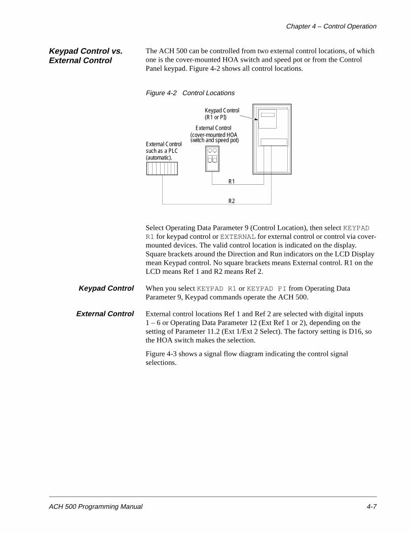
Keypad Control vs. External Control
The ACH 500 can be controlled from two external control locations, of which one is the cover-mounted HOA switch and speed pot or from the Control Panel keypad. Figure 4-2 shows all control locations.
Figure 4-2 Control Locations
Select Operating Data Parameter 9 (Control Location), then select KEYPAD R1 for keypad control or EXTERNAL for external control or control via cover-mounted devices. The valid control location is indicated on the display. Square brackets around the Direction and Run indicators on the LCD Display mean Keypad control. No square brackets means External control. R1 on the LCD means Ref 1 and R2 means Ref 2.
Keypad Control When you select KEYPAD R1 or KEYPAD PI from Operating Data Parameter 9, Keypad commands operate the ACH 500.
External Control External control locations Ref 1 and Ref 2 are selected with digital inputs 1 – 6 or Operating Data Parameter 12 (Ext Ref 1 or 2), depending on the setting of Parameter 11.2 (Ext 1/Ext 2 Select). The factory setting is D16, so the HOA switch makes the selection.
Figure 4-3 shows a signal flow diagram indicating the control signal selections.
Keypad Control(R1 or PI)
External Control(cover-mounted HOA
External Controlsuch as a PLC(automatic).
R1
R2
switch and speed pot)
Chapter 4 – Control Operation
4-8 ACH 500 Programming Manual
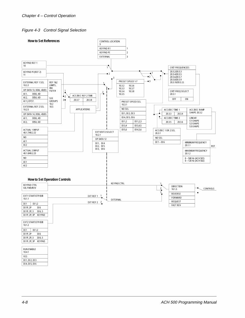
Figure 4-3 Control Signal Selection
CONTROL LOCATION9
KEYPAD R1
KEYPAD PI
EXTERNAL
1
2
3
KEYPAD REF 110
KEYPAD PI (REF 2)11
EXTERNAL REF 1 SEL10.2.2
OP DATA 13, DI3U, 4D(R)
AI 1, DI3U, 4D
AI 2, DI5U, 6D
AI 1 JOYST.
EXTERNAL REF 2 SEL10.2.5
OP DATA 14, DI3U, 4D(R)
AI 1, DI3U, 4D
AI 2, DI5U, 6D
ACTUAL 1 INPUT40.1.7/40.2.22
NO
AI 1
AI 2
REF 1&2LIMITS,INV.FILTER
SEEGROUPS10.210.5
ACTUAL 2 INPUT40.1.8/40.2.23
NO
AI 1
AI 2
1
23
ACC/DEC REF 2 TIME
20.3.7 20.3.8
APPLICATIONS
PRESET SPEED 1-7
10.3.210.3.310.3.410.3.5
10.3.610.3.710.3.8
PRESET SPEED SEL10.3.1
NO SEL
DI 1, DI 2, DI 3
DI 4, DI 5, DI 6
DI 1,2
DI 3,4
DI 5,6
DI 1,2,3
DI 3,4,5
DI 4,5,6
CRIT FREQUENCIES
20.5.2/20.5.3
CRIT FREQ SELECT20.5.1
OFF ON
ACC/DEC TIME 1
20.3.3 20.3.4
ACC/DEC TIME 2
20.3.5 20.3.6
ACC/DEC RAMPSHAPE 20.3.2
LINEARS1-SHAPES2-SHAPES3-SHAPE
ACC/DEC 1 OR 2 SEL20.3.1EXT1/EXT2 SELECT
10.2.1
OP DATA 12
DI 1,DI 2,DI 3,
DI 4DI 5DI 6
NO SEL
DI 1 – DI 6 MINIMUM FREQUENCY20.1.1
MAXIMUM FREQUENCY20.1.2
0 – 500 Hz (ACH 501)
REF
CONTROLSDIRECTION10.1.3
REVERSE
FORWARD
REQUEST
FAST REV
1
2
3
KEYPAD CTRL
EXTERNAL
EXT REF 1
EXT REF 2
1
2
KEYPAD CTRLO/I, FWD/REV
EXT1 START/STP/DIR10.1.1
DI 1 DI 1,2
DI 1P, 2P
DI 1P, 2P, 3
DI 1P, 2P, 3P
RUN ENABLE10.4.1
YES
DI 1, DI 2, DI 3
DI 4, DI 5, DI 6
How to Set References
How to Set Operation Controls
1
2
3
1
2
1
2
3
20.5.4/20.5.520.5.6/20.5.720.5.8/20.5.920.5.10/20.5.11
DI 6
DI 6, 5
KEYPAD
EXT2 START/STP/DIR10.1.2
DI 1 DI 1,2
DI 1P, 2P
DI 1P, 2P, 3
DI 1P, 2P, 3P
DI 6
DI 6, 5
KEYPAD
0 – 120 Hz (ACH 502)
Chapter 4 – Control Operation
ACH 500 Programming Manual 4-9
Keypad Reference 1and Keypad PI
Keypad Reference 1 Operating Data Parameter 10 (Keypad Ref 1) is a direct frequency reference. To set the frequency reference, select Parameter 10 (Keypad Ref 1), press [ * ], then press [Up Arrow] or [Down Arrow] keys to increase or decrease the keypad reference.
When in Keypad control using Reference 1, you can change the Keypad Reference value while monitoring any of the measured values 1 – 8. For example, you can monitor Operating Data Parameter 7 (Output Voltage) while changing the frequency. To do this, select the measured value you prefer, press [ * ], then press [Up Arrow] or [Down Arrow] to increase or decrease the reference frequency. If Operating Data Parameters 1 (Output Frequency) or 2 (Speed) are selected, the display will switch to show Parameter 10 (Keypad Ref 1) while changing the reference and will automatically change back when the arrow key is released.
If the ACH 500 is running with an External Reference and the control location is changed to Keypad R1, it is possible to let the Keypad Ref 1 assume the current value of the External Reference.
Example: The ACH 500 is receiving frequency reference from a transducer via Terminal Block X50. You want to temporarily override the external frequency reference.
1. Set Operating Data Parameter 9 (Control Location) to KEYPAD R1.
2. Press and hold down [Start/Stop] and press [ * ].
Note: If external Start/Stop function is set to Keypad, the ACH 500 will stop, but will read the reference.
The ACH 500 puts the value of External Reference into Operating Data Parameter 10 (Keypad Ref 1) which will make a smooth transition from External to Keypad possible. You may now control the drive manually by Keypad Ref 1.
If you enter Display mode by pressing [ * ] after setting Operating Data Parameter 9 (Control Location) to KEYPAD R1, the value of Operating Data Parameter 10 (Keypad Ref 1) will be the set minimum frequency.
Keypad PI (Ref 2) Keypad PI goes through an application block, where it can be manipulated when the PI-Controller is selected. Keypad PI can be used as controller reference or it can be given its own acceleration/deceleration ramps. Refer to Parameters 20.3.7 (Accel Ref 2 Time) and 20.3.8 (Decel Ref 2 Time).
Chapter 4 – Control Operation
4-10 ACH 500 Programming Manual
External Reference1 and 2
External Reference 1 This is the external frequency reference from control location R1 which is used for HAND. The signal source selection is made with Parameter 10.2.2 (External Ref 1 Sel). The factory default is Analog Input 2 (AI2). This is used for the cover-mounted speed pot.
External Reference 2 External Reference 2 goes through an application block, where it can be manipulated as Keypad Reference 2. The signal source selection is made with Parameter 10.2.5 (External Ref 2 Sel). The default is Analog Input 1 (AI1). This is used for the AUTO speed reference.
Password Protection (Parameter Lock)
Parameter Lock prevents unauthorized persons from altering the parameters. If Parameter Lock is active through Operating Data Parameter 23 (Parameter Lock) or Parameter 10.4.3 (Param. Lock Sel) (Keypad, DI1 – DI6), it is not possible to select the Setting mode to change any ACH 500 parameters, but all parameters may be accessed and viewed.
The ACH 500 Parameter Lock can be controlled with Keypad (Operating Data Parameter 23 (Parameter Lock)) or a digital input. The control location is selected with Parameter 10.4.3 (Param. Lock Sel) (Keypad, DI1 – DI6). To activate the Parameter Lock, set Operating Data Parameter 23 (Parameter Lock) to LOCKED xxx (if the control location is the Keypad) or activate the selected digital input (if the control location is a DI setting).
The Parameter Lock control location is indicated in Operating Data Parameter 23 (Parameter Lock). Characters xxx after the parameter value (OPEN xxx, LOCKED xxx) indicate that the current control location is Keypad.
To open the Parameter Lock, you must enter the correct combination. The combination for all ACH 500 units is 358. When viewing Parameter Lock, enter setting mode and set the 358 code. Press [ * ] to open the Parameter Lock.
ACH 500 Programming Manual 5-1
Chapter 5 – Standard Application Macro Programs
This chapter describes the operation and application suitability of four standard Application macros and the User macro.
The chapter begins with Table 5-1 which lists the macros, suitable applications for each, what each macro controls, and how to access each macro to modify its parameters.
The remainder of this chapter contains the following information for each macro:
• Operation
• Input and Output Signals
• External Connections
• Parameter Settings
User Macro The User macro allows the current parameter settings to be stored in memory.
To store your customized parameters:
1. Access the Start-up Data menu.
2. Change Parameter B (Application) to USER save.
3. Press [ * ] to save.
4. Press [ * ] for each of the remaining Start-up Data Parameters to get back to the Operating Data.
The current settings are now stored in the User macro. Changes can be made to the programming without loosing the parameters saved to the User Macro.
To recall the last saved parameters or User macro:
1. Access the Start-up Data menu.
2. Change Parameter B (Application) to USER load.
3. Press [ * ] to load.
4. Press [ * ] for each of the remaining Start-up Data Parameters to get back to the Operating Data.
Chapter 5 – Standard Application Macro Programs
5-2 ACH 500 Programming Manual
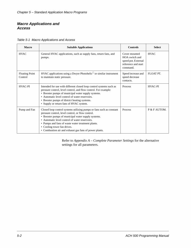
Macro Applications and Access
Table 5-1 Macro Applications and Access
Refer to Appendix A – Complete Parameter Settings for the alternative settings for all parameters.
Macro Suitable Applications Controls Select
HVAC General HVAC applications, such as supply fans, return fans, and pumps.
Cover mounted HOA switch and speed pot. External reference and start command.
HVAC
Floating Point Control
HVAC applications using a Dwyer Photohelic or similar instrument to maintain static pressure.
Speed increase and speed decrease contacts.
FLOAT PT.
HVAC-PI Intended for use with different closed loop control systems such as pressure control, level control, and flow control. For example:• Booster pumps of municipal water supply systems.• Automatic level control of water reservoirs.• Booster pumps of district heating systems.• Supply or return fans of HVAC system.
Process HVAC-PI
Pump and Fan Closed loop control systems utilizing pumps or fans such as constant pressure control, level control, or flow control.• Booster pumps of municipal water supply systems.• Automatic level control of water reservoirs.• Pumps and fans of waste water treatment plants.• Cooling tower fan drives.• Combustion air and exhaust gas fans of power plants.
Process P & F AUTOM.
Chapter 5 – Standard Application Macro Programs
ACH 500 Programming Manual 5-3
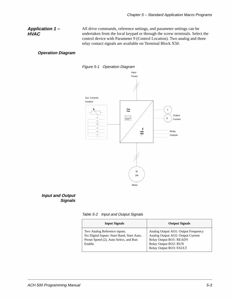
Application 1 – HVAC
All drive commands, reference settings, and parameter settings can be undertaken from the local keypad or through the screw terminals. Select the control device with Parameter 9 (Control Location). Two analog and three relay contact signals are available on Terminal Block X50.
Operation Diagram
Figure 5-1 Operation Diagram
Input and OutputSignals
Table 5-2 Input and Output Signals
Input Signals Output Signals
Two Analog Reference inputs.Six Digital Inputs: Start Hand, Start Auto, Preset Speed (2), Auto Select, and Run Enable.
Analog Output AO1: Output FrequencyAnalog Output AO2: Output CurrentRelay Output RO1: READYRelay Output RO2: RUNRelay Output RO3: FAULT
f
A
M
3Φ
Output
Current
Relay
Outputs
Motor
Ext. Controls
Input
Power
location
Chapter 5 – Standard Application Macro Programs
5-4 ACH 500 Programming Manual
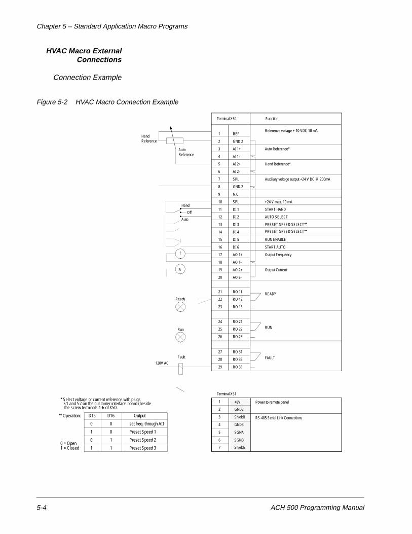
HVAC Macro ExternalConnections
Connection Example
Figure 5-2 HVAC Macro Connection Example
RUN
1
2
3
4
5
6
7
8
9
10
11
12
13
14
15
16
17
18
19
20
21
22
23
24
25
26
27
28
29
REF
GND 2
AI 1+
AI 1-
AI 2+
AI 2-
SPL
GND 2
N.C.
SPL
DI 1
DI 2
DI 3
DI 4
DI 5
DI 6
AO 1+
AO 1-
AO 2+
AO 2-
RO 11
RO 12
RO 13
RO 21
RO 22
RO 23
RO 31
RO 32
RO 33
Function
Reference voltage + 10 VDC 10 mA
Auto Reference*
Hand Reference*
Auxiliary voltage output +24 V DC @ 200mA
+24 V max. 10 mA
START HAND
AUTO SELECT
PRESET SPEED SELECT**
RUN ENABLE
START AUTO
Output Frequency
Output Current
READY
FAULT
A
f
Ready
Run
* Select voltage or current reference with plugs
Fault
120V AC
S1 and S2 on the customer interface board (besidethe screw terminals 1-6 of X50.
** Operation: D15 D16 Output
0
1
0
1
0
0
1
1
set freq. through AI1
Preset Speed 1
Preset Speed 2
Preset Speed 30 = Open1 = Closed
PRESET SPEED SELECT**
Terminal X50
1
2
3
4
5
6
+8V Power to remote panel
RS-485 Serial Link Connections
GND2
Shield1
GND3
SGNA
SGNB
7 Shield2
HandReference
AutoReference
Terminal X51
Hand
Off
Auto

Chapter 5 – Standard Application Macro Programs
ACH 500 Programming Manual 5-5
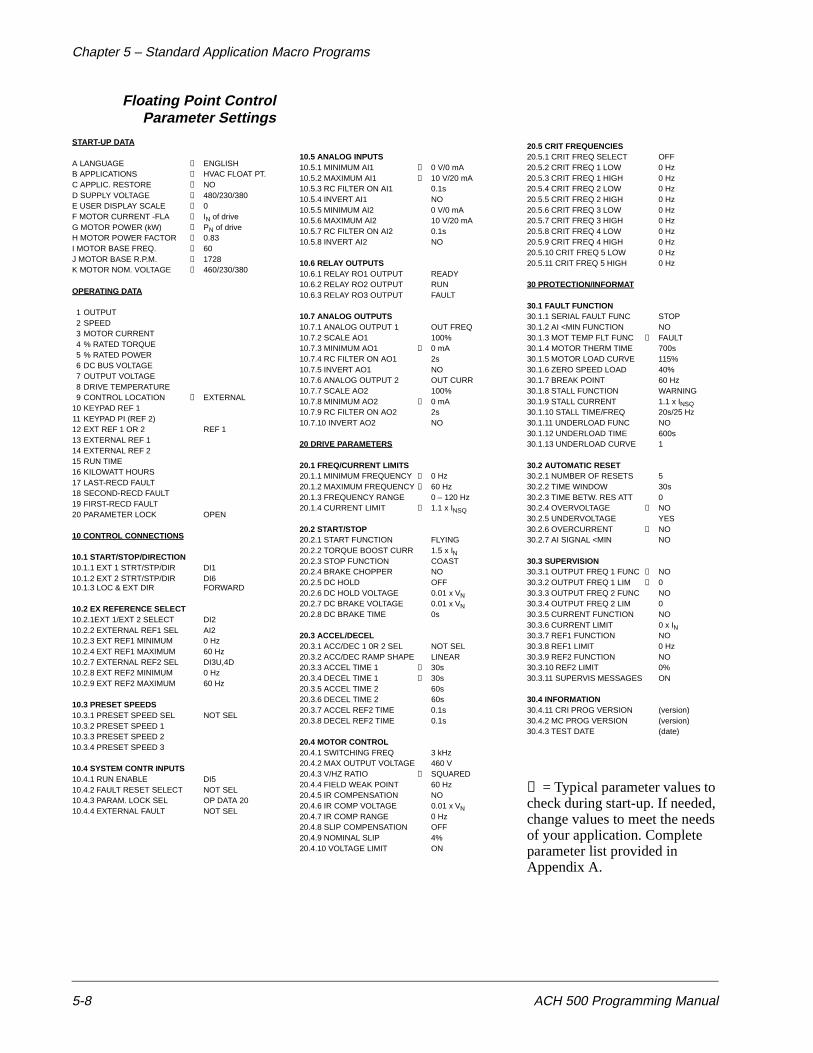
HVACParameter Settings
START-UP DATA
A LANGUAGE → ENGLISHB APPLICATIONS → HVACC APPLIC. RESTORE → NOD SUPPLY VOLTAGE → 480/230/380E USER DISPLAY SCALE → 0F MOTOR CURRENT -FLA → IN of driveG MOTOR POWER (kW) → PN of driveH MOTOR POWER FACTOR → 0.83I MOTOR BASE FREQ. → 60J MOTOR BASE R.P.M. → 1728K MOTOR NOM. VOLTAGE → 460/230/380
OPERATING DATA
1 OUTPUT 2 SPEED3 MOTOR CURRENT4 % RATED TORQUE5 % RATED POWER6 DC BUS VOLTAGE7 OUTPUT VOLTAGE8 DRIVE TEMPERATURE9 CONTROL LOCATION → EXTERNAL
10 KEYPAD REF 111 KEYPAD PI (REF 2)12 EXT REF 1 OR 2 REF 113 EXTERNAL REF 114 EXTERNAL REF 215 RUN TIME16 KILOWATT HOURS17 LAST-RECD FAULT18 SECOND-RECD FAULT19 FIRST-RECD FAULT20 PARAMETER LOCK OPEN
10 CONTROL CONNECTIONS
10.1 START/STOP/DIRECTION10.1.1 EXT 1 STRT/STP/DIR DI110.1.2 EXT 2 STRT/STP/DIR DI610.1.3 LOC & EXT DIR FORWARD
10.2 EX REFERENCE SELECT10.2.1EXT 1/EXT 2 SELECT DI210.2.2 EXTERNAL REF1 SEL AI210.2.3 EXT REF1 MINIMUM 0 Hz10.2.4 EXT REF1 MAXIMUM 60 Hz10.2.7 EXTERNAL REF2 SEL AI110.2.8 EXT REF2 MINIMUM 0 Hz10.2.9 EXT REF2 MAXIMUM 60 Hz
10.3 PRESET SPEEDS10.3.1 PRESET SPEED SEL DI3,410.3.2 PRESET SPEED 1 → 5 Hz10.3.3 PRESET SPEED 2 → 10 Hz10.3.4 PRESET SPEED 3 → 15 Hz
10.4 SYSTEM CONTR INPUTS10.4.1 RUN ENABLE DI510.4.2 FAULT RESET SELECT NOT SEL10.4.3 PARAM. LOCK SEL OP DATA 2010.4.4 EXTERNAL FAULT NOT SEL
10.5 ANALOG INPUTS10.5.1 MINIMUM AI1 → 0 V/0 mA10.5.2 MAXIMUM AI1 → 10 V/20 mA10.5.3 RC FILTER ON AI1 0.1s10.5.4 INVERT AI1 NO10.5.5 MINIMUM AI2 0 V/0 mA10.5.6 MAXIMUM AI2 10 V/20 mA10.5.7 RC FILTER ON AI2 0.1s10.5.8 INVERT AI2 NO
10.6 RELAY OUTPUTS10.6.1 RELAY RO1 OUTPUT READY10.6.2 RELAY RO2 OUTPUT RUN10.6.3 RELAY RO3 OUTPUT FAULT
10.7 ANALOG OUTPUTS10.7.1 ANALOG OUTPUT 1 OUT FREQ10.7.2 SCALE AO1 100%10.7.3 MINIMUM AO1 → 0 mA10.7.4 RC FILTER ON AO1 2s10.7.5 INVERT AO1 NO10.7.6 ANALOG OUTPUT 2 OUT CURR10.7.7 SCALE AO2 100%10.7.8 MINIMUM AO2 → 0 mA10.7.9 RC FILTER ON AO2 2s10.7.10 INVERT AO2 NO
20 DRIVE PARAMETERS
20.1 FREQ/CURRENT LIMITS20.1.1 MINIMUM FREQUENCY → 0 Hz20.1.2 MAXIMUM FREQUENCY → 60 Hz20.1.3 FREQUENCY RANGE 0 – 120 Hz20.1.4 CURRENT LIMIT → 1.1 x INSQ
20.2 START/STOP20.2.1 START FUNCTION FLYING20.2.2 TORQUE BOOST CURR 1.5 x IN20.2.3 STOP FUNCTION COAST20.2.4 BRAKE CHOPPER NO20.2.5 DC HOLD OFF20.2.6 DC HOLD VOLTAGE 0.01 x VN20.2.7 DC BRAKE VOLTAGE 0.01 x VN20.2.8 DC BRAKE TIME 0s
20.3 ACCEL/DECEL20.3.1 ACC/DEC 1 0R 2 SEL NOT SEL20.3.2 ACC/DEC RAMP SHAPE LINEAR20.3.3 ACCEL TIME 1 → 30s20.3.4 DECEL TIME 1 → 30s20.3.5 ACCEL TIME 2 60s20.3.6 DECEL TIME 2 60s20.3.7 ACCEL REF2 TIME 0.1s20.3.8 DECEL REF2 TIME 0.1s
20.4 MOTOR CONTROL20.4.1 SWITCHING FREQ 3 kHz20.4.2 MAX OUTPUT VOLTAGE 460 V20.4.3 V/HZ RATIO → SQUARED20.4.4 FIELD WEAK POINT 60 Hz20.4.5 IR COMPENSATION NO20.4.6 IR COMP VOLTAGE 0.01 x VN20.4.7 IR COMP RANGE 0 Hz20.4.8 SLIP COMPENSATION OFF20.4.9 NOMINAL SLIP 4%20.4.10 VOLTAGE LIMIT ON
20.5 CRIT FREQUENCIES20.5.1 CRIT FREQ SELECT OFF20.5.2 CRIT FREQ 1 LOW 0 Hz20.5.3 CRIT FREQ 1 HIGH 0 Hz20.5.4 CRIT FREQ 2 LOW 0 Hz20.5.5 CRIT FREQ 2 HIGH 0 Hz20.5.6 CRIT FREQ 3 LOW 0 Hz20.5.7 CRIT FREQ 3 HIGH 0 Hz20.5.8 CRIT FREQ 4 LOW 0 Hz20.5.9 CRIT FREQ 4 HIGH 0 Hz20.5.10 CRIT FREQ 5 LOW 0 Hz20.5.11 CRIT FREQ 5 HIGH 0 Hz
30 PROTECTION/INFORMAT
30.1 FAULT FUNCTION30.1.1 SERIAL FAULT FUNC STOP30.1.2 AI <MIN FUNCTION NO30.1.3 MOT TEMP FLT FUNC → FAULT30.1.4 MOTOR THERM TIME 700s30.1.5 MOTOR LOAD CURVE 115%30.1.6 ZERO SPEED LOAD 40%30.1.7 BREAK POINT 60 Hz30.1.8 STALL FUNCTION WARNING30.1.9 STALL CURRENT 1.1 x INSQ30.1.10 STALL TIME/FREQ 20s/25 Hz30.1.11 UNDERLOAD FUNC NO30.1.12 UNDERLOAD TIME 600s30.1.13 UNDERLOAD CURVE 1
30.2 AUTOMATIC RESET30.2.1 NUMBER OF RESETS 530.2.2 TIME WINDOW 30s30.2.3 TIME BETW. RES ATT 030.2.4 OVERVOLTAGE → NO30.2.5 UNDERVOLTAGE YES30.2.6 OVERCURRENT → NO30.2.7 AI SIGNAL <MIN NO
30.3 SUPERVISION30.3.1 OUTPUT FREQ 1 FUNC → NO30.3.2 OUTPUT FREQ 1 LIM → 030.3.3 OUTPUT FREQ 2 FUNC NO30.3.4 OUTPUT FREQ 2 LIM 030.3.5 CURRENT FUNCTION NO30.3.6 CURRENT LIMIT 0 x IN30.3.7 REF1 FUNCTION NO30.3.8 REF1 LIMIT 0 Hz30.3.9 REF2 FUNCTION NO30.3.10 REF2 LIMIT 0%30.3.11 SUPERVIS MESSAGES ON
30.4 INFORMATION30.4.11 CRI PROG VERSION (version)30.4.2 MC PROG VERSION (version)30.4.3 TEST DATE (date)
→ = Typical parameter values to check during start-up. If needed, change values to meet the needs of your application. Complete parameter list provided in Appendix A.
Chapter 5 – Standard Application Macro Programs
5-6 ACH 500 Programming Manual
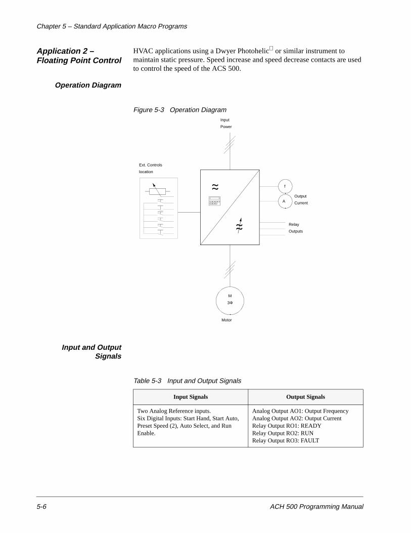
Application 2 – Floating Point Control
HVAC applications using a Dwyer Photohelic or similar instrument to maintain static pressure. Speed increase and speed decrease contacts are used to control the speed of the ACS 500.
Operation Diagram
Figure 5-3 Operation Diagram
Input and OutputSignals
Table 5-3 Input and Output Signals
Input Signals Output Signals
Two Analog Reference inputs.Six Digital Inputs: Start Hand, Start Auto, Preset Speed (2), Auto Select, and Run Enable.
Analog Output AO1: Output FrequencyAnalog Output AO2: Output CurrentRelay Output RO1: READYRelay Output RO2: RUNRelay Output RO3: FAULT
f
A
M
3Φ
Output
Current
Relay
Outputs
Motor
Ext. Controls
Input
Power
location
Chapter 5 – Standard Application Macro Programs
ACH 500 Programming Manual 5-7
Floating Point ControlExternal Connections
Connection Example
Figure 5-4 Connection Example
RUN
1
2
3
4
5
6
7
8
9
10
11
12
13
14
15
16
17
18
19
20
21
22
23
24
25
26
27
28
29
REF
GND 2
AI 1+
AI 1-
AI 2+
AI 2-
SPL
GND 2
N.C.
SPL
DI 1
DI 2
DI 3
DI 4
DI 5
DI 6
AO 1+
AO 1-
AO 2+
AO 2-
RO 11
RO 12
RO 13
RO 21
RO 22
RO 23
RO 31
RO 32
RO 33
Function
Reference voltage + 10 VDC 10 mA
Auto Reference*
Hand Reference*
Auxiliary voltage output +24 V DC @ 200mA
+24 V max. 10 mA
START HAND
AUTO SELECT
ACCEL
RUN ENABLE
START AUTO
Output Frequency
Output Current
READY
FAULT
A
f
Ready
Run
* Select voltage or current reference with plugs
Fault
120V AC
S1 and S2 on the customer interface board (besidethe screw terminals 1-6 of X50.
DECEL
Terminal X50
1
2
3
4
5
6
+8V Power to remote panel
RS-485 Serial Link Connections
GND2
Shield1
GND3
SGNA
SGNB
7 Shield2
HandReference
AutoReference
Terminal X51
Hand
Off
Auto
Chapter 5 – Standard Application Macro Programs
5-8 ACH 500 Programming Manual
Floating Point ControlParameter Settings
START-UP DATA
A LANGUAGE → ENGLISHB APPLICATIONS → HVAC FLOAT PT.C APPLIC. RESTORE → NOD SUPPLY VOLTAGE → 480/230/380E USER DISPLAY SCALE → 0F MOTOR CURRENT -FLA → IN of driveG MOTOR POWER (kW) → PN of driveH MOTOR POWER FACTOR → 0.83I MOTOR BASE FREQ. → 60J MOTOR BASE R.P.M. → 1728K MOTOR NOM. VOLTAGE → 460/230/380
OPERATING DATA
1 OUTPUT 2 SPEED3 MOTOR CURRENT4 % RATED TORQUE5 % RATED POWER6 DC BUS VOLTAGE7 OUTPUT VOLTAGE8 DRIVE TEMPERATURE9 CONTROL LOCATION → EXTERNAL
10 KEYPAD REF 111 KEYPAD PI (REF 2)12 EXT REF 1 OR 2 REF 113 EXTERNAL REF 114 EXTERNAL REF 215 RUN TIME16 KILOWATT HOURS17 LAST-RECD FAULT18 SECOND-RECD FAULT19 FIRST-RECD FAULT20 PARAMETER LOCK OPEN
10 CONTROL CONNECTIONS
10.1 START/STOP/DIRECTION10.1.1 EXT 1 STRT/STP/DIR DI110.1.2 EXT 2 STRT/STP/DIR DI610.1.3 LOC & EXT DIR FORWARD
10.2 EX REFERENCE SELECT10.2.1EXT 1/EXT 2 SELECT DI210.2.2 EXTERNAL REF1 SEL AI210.2.3 EXT REF1 MINIMUM 0 Hz10.2.4 EXT REF1 MAXIMUM 60 Hz10.2.7 EXTERNAL REF2 SEL DI3U,4D10.2.8 EXT REF2 MINIMUM 0 Hz10.2.9 EXT REF2 MAXIMUM 60 Hz
10.3 PRESET SPEEDS10.3.1 PRESET SPEED SEL NOT SEL10.3.2 PRESET SPEED 110.3.3 PRESET SPEED 210.3.4 PRESET SPEED 3
10.4 SYSTEM CONTR INPUTS10.4.1 RUN ENABLE DI510.4.2 FAULT RESET SELECT NOT SEL10.4.3 PARAM. LOCK SEL OP DATA 2010.4.4 EXTERNAL FAULT NOT SEL
10.5 ANALOG INPUTS10.5.1 MINIMUM AI1 → 0 V/0 mA10.5.2 MAXIMUM AI1 → 10 V/20 mA10.5.3 RC FILTER ON AI1 0.1s10.5.4 INVERT AI1 NO10.5.5 MINIMUM AI2 0 V/0 mA10.5.6 MAXIMUM AI2 10 V/20 mA10.5.7 RC FILTER ON AI2 0.1s10.5.8 INVERT AI2 NO
10.6 RELAY OUTPUTS10.6.1 RELAY RO1 OUTPUT READY10.6.2 RELAY RO2 OUTPUT RUN10.6.3 RELAY RO3 OUTPUT FAULT
10.7 ANALOG OUTPUTS10.7.1 ANALOG OUTPUT 1 OUT FREQ10.7.2 SCALE AO1 100%10.7.3 MINIMUM AO1 → 0 mA10.7.4 RC FILTER ON AO1 2s10.7.5 INVERT AO1 NO10.7.6 ANALOG OUTPUT 2 OUT CURR10.7.7 SCALE AO2 100%10.7.8 MINIMUM AO2 → 0 mA10.7.9 RC FILTER ON AO2 2s10.7.10 INVERT AO2 NO
20 DRIVE PARAMETERS
20.1 FREQ/CURRENT LIMITS20.1.1 MINIMUM FREQUENCY → 0 Hz20.1.2 MAXIMUM FREQUENCY → 60 Hz20.1.3 FREQUENCY RANGE 0 – 120 Hz20.1.4 CURRENT LIMIT → 1.1 x INSQ
20.2 START/STOP20.2.1 START FUNCTION FLYING20.2.2 TORQUE BOOST CURR 1.5 x IN20.2.3 STOP FUNCTION COAST20.2.4 BRAKE CHOPPER NO20.2.5 DC HOLD OFF20.2.6 DC HOLD VOLTAGE 0.01 x VN20.2.7 DC BRAKE VOLTAGE 0.01 x VN20.2.8 DC BRAKE TIME 0s
20.3 ACCEL/DECEL20.3.1 ACC/DEC 1 0R 2 SEL NOT SEL20.3.2 ACC/DEC RAMP SHAPE LINEAR20.3.3 ACCEL TIME 1 → 30s20.3.4 DECEL TIME 1 → 30s20.3.5 ACCEL TIME 2 60s20.3.6 DECEL TIME 2 60s20.3.7 ACCEL REF2 TIME 0.1s20.3.8 DECEL REF2 TIME 0.1s
20.4 MOTOR CONTROL20.4.1 SWITCHING FREQ 3 kHz20.4.2 MAX OUTPUT VOLTAGE 460 V20.4.3 V/HZ RATIO → SQUARED20.4.4 FIELD WEAK POINT 60 Hz20.4.5 IR COMPENSATION NO20.4.6 IR COMP VOLTAGE 0.01 x VN20.4.7 IR COMP RANGE 0 Hz20.4.8 SLIP COMPENSATION OFF20.4.9 NOMINAL SLIP 4%20.4.10 VOLTAGE LIMIT ON
20.5 CRIT FREQUENCIES20.5.1 CRIT FREQ SELECT OFF20.5.2 CRIT FREQ 1 LOW 0 Hz20.5.3 CRIT FREQ 1 HIGH 0 Hz20.5.4 CRIT FREQ 2 LOW 0 Hz20.5.5 CRIT FREQ 2 HIGH 0 Hz20.5.6 CRIT FREQ 3 LOW 0 Hz20.5.7 CRIT FREQ 3 HIGH 0 Hz20.5.8 CRIT FREQ 4 LOW 0 Hz20.5.9 CRIT FREQ 4 HIGH 0 Hz20.5.10 CRIT FREQ 5 LOW 0 Hz20.5.11 CRIT FREQ 5 HIGH 0 Hz
30 PROTECTION/INFORMAT
30.1 FAULT FUNCTION30.1.1 SERIAL FAULT FUNC STOP30.1.2 AI <MIN FUNCTION NO30.1.3 MOT TEMP FLT FUNC → FAULT30.1.4 MOTOR THERM TIME 700s30.1.5 MOTOR LOAD CURVE 115%30.1.6 ZERO SPEED LOAD 40%30.1.7 BREAK POINT 60 Hz30.1.8 STALL FUNCTION WARNING30.1.9 STALL CURRENT 1.1 x INSQ30.1.10 STALL TIME/FREQ 20s/25 Hz30.1.11 UNDERLOAD FUNC NO30.1.12 UNDERLOAD TIME 600s30.1.13 UNDERLOAD CURVE 1
30.2 AUTOMATIC RESET30.2.1 NUMBER OF RESETS 530.2.2 TIME WINDOW 30s30.2.3 TIME BETW. RES ATT 030.2.4 OVERVOLTAGE → NO30.2.5 UNDERVOLTAGE YES30.2.6 OVERCURRENT → NO30.2.7 AI SIGNAL <MIN NO
30.3 SUPERVISION30.3.1 OUTPUT FREQ 1 FUNC → NO30.3.2 OUTPUT FREQ 1 LIM → 030.3.3 OUTPUT FREQ 2 FUNC NO30.3.4 OUTPUT FREQ 2 LIM 030.3.5 CURRENT FUNCTION NO30.3.6 CURRENT LIMIT 0 x IN30.3.7 REF1 FUNCTION NO30.3.8 REF1 LIMIT 0 Hz30.3.9 REF2 FUNCTION NO30.3.10 REF2 LIMIT 0%30.3.11 SUPERVIS MESSAGES ON
30.4 INFORMATION30.4.11 CRI PROG VERSION (version)30.4.2 MC PROG VERSION (version)30.4.3 TEST DATE (date)
→ = Typical parameter values to check during start-up. If needed, change values to meet the needs of your application. Complete parameter list provided in Appendix A.
Chapter 5 – Standard Application Macro Programs
ACH 500 Programming Manual 5-9
Application 3 –HVAC-PI
Start/Stop from two different places, Control Location selection, Run Enable selection, one Preset Speed selection, Reference setting and actual value feedback through screw terminal inputs. Reference setting also possible internally with the keypad.
Place A is intended for direct speed setting with a reference signal and Place B is intended for closed-loop speed control using the same reference as Place A. Preset speed overrides external analog settings.
Operation Diagram
Figure 5-5 Operation Diagram
Input and OutputSignals
Table 5-4 Input and Output Signals
Input Signals Output Signals
Two Analog Reference inputs.Six Digital Inputs: Start Hand, Start Auto, Preset Speed (2), Auto Select, and Run Enable.
Analog Output AO1: Output FrequencyAnalog Output AO2: Output CurrentRelay Output RO1: READYRelay Output RO2: RUNRelay Output RO3: FAULT
f
A
M
3Φ
Output
Current
Relay
Outputs
Motor
Ext. Controls
Input
Power
location

Chapter 5 – Standard Application Macro Programs
5-10 ACH 500 Programming Manual
HVAC-PI ExternalConnections
Process Control = Auto
Direct Speed Control = Manual
Connection Example
Figure 5-6 Connection Example
RUN
1
2
3
4
5
6
7
8
9
10
11
12
13
14
15
16
17
18
19
20
21
22
23
24
25
26
27
28
29
REF
GND 2
AI 1+
AI 1-
AI 2+
AI 2-
SPL
GND 2
N.C.
SPL
DI 1
DI 2
DI 3
DI 4
DI 5
DI 6
AO 1+
AO 1-
AO 2+
AO 2-
RO 11
RO 12
RO 13
RO 21
RO 22
RO 23
RO 31
RO 32
RO 33
Function
Reference voltage + 10 VDC 10 mA
Actual 1
Hand Reference* and
Auxiliary voltage output +24 V DC @ 200mA
+24 V max. 10 mA
START HAND
AUTO SELECT
PRESET SPEED SELECT**
RUN ENABLE
START AUTO
Output Frequency
Output Current
READY
FAULT
A
f
Ready
Run
* Select voltage or current reference with plugs
Fault
120V AC
S1 and S2 on the customer interface board (besidethe screw terminals 1-6 of X50.
** Operation: D15 D16 Output
0
1
0
1
0
0
1
1
set freq. through AI1
Preset Speed 1
Preset Speed 2
Preset Speed 30 = Open1 = Closed
PRESET SPEED SELECT**
Terminal X50
1
2
3
4
5
6
+8V Power to remote panel
RS-485 Serial Link Connections
GND2
Shield1
GND3
SGNA
SGNB
7 Shield2
HandReference
AutoFeedback
Terminal X51
Hand
Off
Auto
Auto Setpoint
Chapter 5 – Standard Application Macro Programs
ACH 500 Programming Manual 5-11
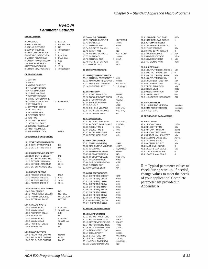
HVAC-PIParameter Settings
START-UP DATA
A LANGUAGE → ENGLISHB APPLICATIONS → PI-CONTROLC APPLIC. RESTORE → NOD SUPPLY VOLTAGE → 480/230/380E USER DISPLAY SCALE → 0F MOTOR CURRENT -FLA → IN of driveG MOTOR POWER (kW) → PN of driveH MOTOR POWER FACTOR → 0.83I MOTOR BASE FREQ. → 60J MOTOR BASE R.P.M. → 1728K MOTOR NOM. VOLTAGE → 460/230/380
OPERATING DATA
1 OUTPUT 2 SPEED3 MOTOR CURRENT4 % RATED TORQUE5 % RATED POWER6 DC BUS VOLTAGE7 OUTPUT VOLTAGE8 DRIVE TEMPERATURE9 CONTROL LOCATION → EXTERNAL
10 KEYPAD REF 111 KEYPAD PI (REF 2)12 EXT REF 1 OR 2 REF 213 EXTERNAL REF 114 EXTERNAL REF 215 RUN TIME16 KILOWATT HOURS17 LAST-RECD FAULT18 SECOND-RECD FAULT19 FIRST-RECD FAULT20 PARAMETER LOCK OPEN
10 CONTROL CONNECTIONS
10.1 START/STOP/DIRECTION10.1.1 EXT 1 STRT/STP/DIR DI110.1.2 EXT 2 STRT/STP/DIR DI6
10.2 EX REFERENCE SELECT10.2.1EXT 1/EXT 2 SELECT DI210.2.2 EXTERNAL REF1 SEL AI210.2.3 EXT REF1 MINIMUM 0 Hz10.2.4 EXT REF1 MAXIMUM 60 Hz10.2.7 EXTERNAL REF2 SEL AI2
10.3 PRESET SPEEDS10.3.1 PRESET SPEED SEL DI3,410.3.2 PRESET SPEED 1 → 5 Hz10.3.3 PRESET SPEED 2 → 10 Hz10.3.4 PRESET SPEED 3 → 15 Hz
10.4 SYSTEM CONTR INPUTS10.4.1 RUN ENABLE DI510.4.2 FAULT RESET SELECT NOT SEL10.4.3 PARAM. LOCK SEL OP DATA 2010.4.4 EXTERNAL FAULT NOT SEL
10.5 ANALOG INPUTS10.5.1 MINIMUM AI1 → 0 V/0 mA10.5.2 MAXIMUM AI1 → 10 V/20 mA10.5.3 RC FILTER ON AI1 0.1s10.5.4 INVERT AI1 NO10.5.5 MINIMUM AI2 0 V/0 mA10.5.6 MAXIMUM AI2 10 V/20 mA10.5.7 RC FILTER ON AI2 0.1s10.5.8 INVERT AI2 NO
10.6 RELAY OUTPUTS10.6.1 RELAY RO1 OUTPUT READY10.6.2 RELAY RO2 OUTPUT RUN10.6.3 RELAY RO3 OUTPUT FAULT
10.7 ANALOG OUTPUTS10.7.1 ANALOG OUTPUT 1 OUT FREQ10.7.2 SCALE AO1 100%10.7.3 MINIMUM AO1 → 0 mA10.7.4 RC FILTER ON AO1 2s10.7.5 INVERT AO1 NO10.7.6 ANALOG OUTPUT 2 OUT CURR10.7.7 SCALE AO2 100%10.7.8 MINIMUM AO2 → 0 mA10.7.9 RC FILTER ON AO2 2s10.7.10 INVERT AO2 NO
20 DRIVE PARAMETERS
20.1 FREQ/CURRENT LIMITS20.1.1 MINIMUM FREQUENCY → 0 Hz20.1.2 MAXIMUM FREQUENCY → 60 Hz20.1.3 FREQUENCY RANGE 0 – 120 Hz20.1.4 CURRENT LIMIT → 1.1 x INSQ
20.2 START/STOP20.2.1 START FUNCTION RAMP20.2.2 TORQUE BOOST CURR 1.5 x IN20.2.3 STOP FUNCTION COAST20.2.4 BRAKE CHOPPER NO20.2.5 DC HOLD OFF20.2.6 DC HOLD VOLTAGE 0.01 x VN20.2.7 DC BRAKE VOLTAGE 0.01 x VN20.2.8 DC BRAKE TIME 0s
20.3 ACCEL/DECEL20.3.1 ACC/DEC 1 0R 2 SEL NOT SEL20.3.2 ACC/DEC RAMP SHAPE LINEAR20.3.3 ACCEL TIME 1 → 30s20.3.4 DECEL TIME 1 → 30s20.3.7 ACCEL REF2 TIME 0.1s20.3.8 DECEL REF2 TIME 0.1s
20.4 MOTOR CONTROL20.4.1 SWITCHING FREQ 3 kHz20.4.2 MAX OUTPUT VOLTAGE 460 V20.4.3 V/HZ RATIO → SQUARED20.4.4 FIELD WEAK POINT 60 Hz20.4.5 IR COMPENSATION NO20.4.6 IR COMP VOLTAGE 0.01 x VN20.4.7 IR COMP RANGE 0 Hz20.4.8 SLIP COMPENSATION OFF20.4.9 NOMINAL SLIP 4%20.4.10 VOLTAGE LIMIT ON
20.5 CRIT FREQUENCIES20.5.1 CRIT FREQ SELECT OFF20.5.2 CRIT FREQ 1 LOW 0 Hz20.5.3 CRIT FREQ 1 HIGH 0 Hz20.5.4 CRIT FREQ 2 LOW 0 Hz20.5.5 CRIT FREQ 2 HIGH 0 Hz20.5.6 CRIT FREQ 3 LOW 0 Hz20.5.7 CRIT FREQ 3 HIGH 0 Hz20.5.8 CRIT FREQ 4 LOW 0 Hz20.5.9 CRIT FREQ 4 HIGH 0 Hz20.5.10 CRIT FREQ 5 LOW 0 Hz20.5.11 CRIT FREQ 5 HIGH 0 Hz
30 PROTECTION/INFORMAT
30.1 FAULT FUNCTION30.1.1 SERIAL FAULT FUNC STOP30.1.2 AI <MIN FUNCTION FAULT30.1.3 MOT TEMP FLT FUNC → FAULT30.1.4 MOTOR THERM TIME 700s30.1.5 MOTOR LOAD CURVE 115%30.1.6 ZERO SPEED LOAD 40%30.1.7 BREAK POINT 60 Hz30.1.8 STALL FUNCTION WARNING30.1.9 STALL CURRENT 1.5 x IN30.1.10 STALL TIME/FREQ 20s/25 Hz30.1.11 UNDERLOAD FUNC NO
30.1.12 UNDERLOAD TIME 600s30.1.13 UNDERLOAD CURVE 130.2 AUTOMATIC RESET30.2.1 NUMBER OF RESETS 230.2.2 TIME WINDOW 30s30.2.3 TIME BETW. RES ATT 030.2.4 OVERVOLTAGE → NO30.2.5 UNDERVOLTAGE YES30.2.6 OVERCURRENT → NO30.2.7 AI SIGNAL <MIN YES
30.3 SUPERVISION30.3.1 OUTPUT FREQ 1 FUNC → NO30.3.2 OUTPUT FREQ 1 LIM → 030.3.3 OUTPUT FREQ 2 FUNC NO30.3.4 OUTPUT FREQ 2 LIM 030.3.5 CURRENT FUNCTION NO30.3.6 CURRENT LIMIT 0 x IN30.3.7 REF1 FUNCTION NO30.3.8 REF1 LIMIT 0 Hz30.3.9 REF2 FUNCTION NO30.3.10 REF2 LIMIT 0%30.3.11 SUPERVIS MESSAGES ON
30.4 INFORMATION30.4.11 CRI PROG VERSION (version)30.4.2 MC PROG VERSION (version)30.4.3 TEST DATE (date)
40 APPLICATION PARAMETERS
40.1 PI-CONTROL40.1.1 PI-CONT GAIN 100%40.1.2 PI-CONT I-TIME 60s40.1.3 PI-CONT MIN LIMIT 25 Hz40.1.4 PI-CONT MAX LIMIT 60 Hz40.1.5 ERROR VALUE INVERT NO40.1.6 ACTUAL VALUE SEL ACT 140.1.7 ACTUAL 1 INPUT AI140.1.8 ACTUAL 2 INPUT NO40.1.9 ACT 1 MIN SCALE 040.1.10 ACT 1 MAX SCALE 10040.1.11 ACT 2 MIN SCALE 040.1.12 ACT 2 MAX SCALE 0
→ = Typical parameter values to check during start-up. If needed, change values to meet the needs of your application. Complete parameter list provided in Appendix A.
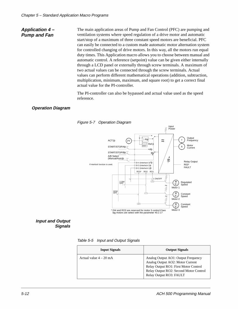
Chapter 5 – Standard Application Macro Programs
5-12 ACH 500 Programming Manual
Application 4 – Pump and Fan
The main application areas of Pump and Fan Control (PFC) are pumping and ventilation systems where speed regulation of a drive motor and automatic start/stop of a maximum of three constant speed motors are beneficial. PFC can easily be connected to a custom made automatic motor alternation system for controlled changing of drive motors. In this way, all the motors run equal duty times. This Application macro allows you to choose between manual and automatic control. A reference (setpoint) value can be given either internally through a LCD panel or externally through screw terminals. A maximum of two actual values can be connected through the screw terminals. Actual values can perform different mathematical operations (addition, subtraction, multiplication, minimum, maximum, and square root) to get a correct final actual value for the PI-controller.
The PI-controller can also be bypassed and actual value used as the speed reference.
Operation Diagram
Figure 5-7 Operation Diagram
Input and OutputSignals
Table 5-5 Input and Output Signals
Input Signals Output Signals
Actual value 4 – 20 mA Analog Output AO1: Output FrequencyAnalog Output AO2: Motor CurrentRelay Output RO1: First Motor ControlRelay Output RO2: Second Motor ControlRelay Output RO3: FAULT
f
A
M3∼
Motor
Relay Output
Motor 1
Input
R03*FAULT
Current
OutputFrequencyPIþ
Aþ
Bþ
PT
START/STOP/Aþ
START/STOP/Bþ
A/B Select(Manual/Auto)þ
DI 4 (Interlock 3)*þDI 3 (Interlock 2)þDI 2 (Interlock 1)þ
RO3* RO2 RO1
M3∼
Motor 2
M3∼
Motor 3
RegulatedSpeed
ConstantSpeed
ConstantSpeed
1 ON/OFF
2 ON/OFF
3ON/OFF
* DI4 and RO3 are reserved for motor 3 control if twolag motors are select with the parameter 40.2.17
Ref.þ
ACT1þ
Power
If interlock function is used.
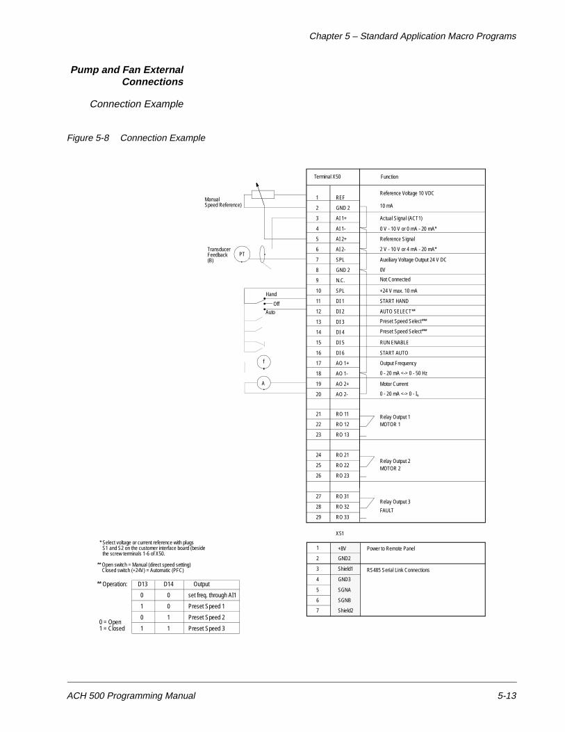
Chapter 5 – Standard Application Macro Programs
ACH 500 Programming Manual 5-13
Pump and Fan ExternalConnections
Connection Example
Figure 5-8 Connection Example
1
2
3
4
5
6
7
8
9
10
11
12
13
14
15
16
17
18
19
20
21
22
23
24
25
26
27
28
29
REF
GND 2
AI 1+
AI 1-
AI 2+
AI 2-
SPL
GND 2
N.C.
SPL
DI 1
DI 2
DI 3
DI 4
DI 5
DI 6
AO 1+
AO 1-
AO 2+
AO 2-
RO 11
RO 12
RO 13
RO 21
RO 22
RO 23
RO 31
RO 32
RO 33
Function
Reference Voltage 10 VDC
Actual Signal (ACT1)
Reference Signal
Auxiliary Voltage Output 24 V DC
+24 V max. 10 mA
START HAND
AUTO SELECT**
RUN ENABLE
START AUTO
Output Frequency
Motor Current
Relay Output 1
FAULT
A
f
* Select voltage or current reference with plugsS1 and S2 on the customer interface board (besidethe screw terminals 1-6 of X50.
** Open switch = Manual (direct speed setting)
Terminal X50
1
2
3
4
5
6
+8V Power to Remote Panel
RS485 Serial Link Connections
GND2
Shield1
GND3
SGNA
SGNB
7 Shield2
TransducerFeedback(B)
ManualSpeed Reference)
PT
10 mA
0 V - 10 V or 0 mA - 20 mA*
2 V - 10 V or 4 mA - 20 mA*
0V
Not Connected
0 - 20 mA <-> 0 - 50 Hz
0 - 20 mA <-> 0 - IN
MOTOR 1
Relay Output 2MOTOR 2
Relay Output 3
X51
Closed switch (+24V) = Automatic (PFC)
Preset Speed Select***
Preset Speed Select***
** Operation: D13 D14 Output
0
1
0
1
0
0
1
1
set freq. through AI1
Preset Speed 1
Preset Speed 2
Preset Speed 30 = Open1 = Closed
Hand
Off
Auto
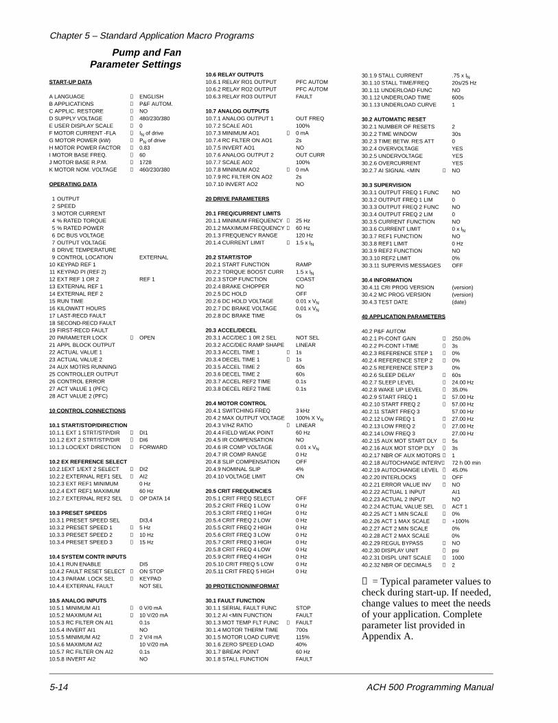
Chapter 5 – Standard Application Macro Programs
5-14 ACH 500 Programming Manual
Pump and FanParameter Settings
START-UP DATA
A LANGUAGE → ENGLISHB APPLICATIONS → P&F AUTOM.C APPLIC. RESTORE → NOD SUPPLY VOLTAGE → 480/230/380E USER DISPLAY SCALE → 0F MOTOR CURRENT -FLA → IN of driveG MOTOR POWER (kW) → PN of driveH MOTOR POWER FACTOR → 0.83I MOTOR BASE FREQ. → 60J MOTOR BASE R.P.M. → 1728K MOTOR NOM. VOLTAGE → 460/230/380
OPERATING DATA
1 OUTPUT 2 SPEED3 MOTOR CURRENT4 % RATED TORQUE5 % RATED POWER6 DC BUS VOLTAGE7 OUTPUT VOLTAGE8 DRIVE TEMPERATURE9 CONTROL LOCATION EXTERNAL
10 KEYPAD REF 111 KEYPAD PI (REF 2)12 EXT REF 1 OR 2 REF 113 EXTERNAL REF 114 EXTERNAL REF 215 RUN TIME16 KILOWATT HOURS17 LAST-RECD FAULT18 SECOND-RECD FAULT19 FIRST-RECD FAULT20 PARAMETER LOCK → OPEN21 APPL BLOCK OUTPUT22 ACTUAL VALUE 123 ACTUAL VALUE 224 AUX MOTRS RUNNING25 CONTROLLER OUTPUT26 CONTROL ERROR27 ACT VALUE 1 (PFC)28 ACT VALUE 2 (PFC)
10 CONTROL CONNECTIONS
10.1 START/STOP/DIRECTION10.1.1 EXT 1 STRT/STP/DIR → DI110.1.2 EXT 2 STRT/STP/DIR → DI610.1.3 LOC/EXT DIRECTION → FORWARD
10.2 EX REFERENCE SELECT10.2.1EXT 1/EXT 2 SELECT → DI210.2.2 EXTERNAL REF1 SEL → AI210.2.3 EXT REF1 MINIMUM 0 Hz10.2.4 EXT REF1 MAXIMUM 60 Hz10.2.7 EXTERNAL REF2 SEL → OP DATA 14
10.3 PRESET SPEEDS10.3.1 PRESET SPEED SEL DI3,410.3.2 PRESET SPEED 1 → 5 Hz10.3.3 PRESET SPEED 2 → 10 Hz10.3.4 PRESET SPEED 3 → 15 Hz
10.4 SYSTEM CONTR INPUTS10.4.1 RUN ENABLE DI510.4.2 FAULT RESET SELECT → ON STOP10.4.3 PARAM. LOCK SEL → KEYPAD10.4.4 EXTERNAL FAULT NOT SEL
10.5 ANALOG INPUTS10.5.1 MINIMUM AI1 → 0 V/0 mA10.5.2 MAXIMUM AI1 → 10 V/20 mA10.5.3 RC FILTER ON AI1 0.1s10.5.4 INVERT AI1 NO10.5.5 MINIMUM AI2 → 2 V/4 mA10.5.6 MAXIMUM AI2 10 V/20 mA10.5.7 RC FILTER ON AI2 0.1s10.5.8 INVERT AI2 NO
10.6 RELAY OUTPUTS10.6.1 RELAY RO1 OUTPUT PFC AUTOM10.6.2 RELAY RO2 OUTPUT PFC AUTOM10.6.3 RELAY RO3 OUTPUT FAULT
10.7 ANALOG OUTPUTS10.7.1 ANALOG OUTPUT 1 OUT FREQ10.7.2 SCALE AO1 100%10.7.3 MINIMUM AO1 → 0 mA10.7.4 RC FILTER ON AO1 2s10.7.5 INVERT AO1 NO10.7.6 ANALOG OUTPUT 2 OUT CURR10.7.7 SCALE AO2 100%10.7.8 MINIMUM AO2 → 0 mA10.7.9 RC FILTER ON AO2 2s10.7.10 INVERT AO2 NO
20 DRIVE PARAMETERS
20.1 FREQ/CURRENT LIMITS20.1.1 MINIMUM FREQUENCY → 25 Hz20.1.2 MAXIMUM FREQUENCY → 60 Hz20.1.3 FREQUENCY RANGE 120 Hz20.1.4 CURRENT LIMIT → 1.5 x IN
20.2 START/STOP20.2.1 START FUNCTION RAMP20.2.2 TORQUE BOOST CURR 1.5 x IN20.2.3 STOP FUNCTION COAST20.2.4 BRAKE CHOPPER NO20.2.5 DC HOLD OFF20.2.6 DC HOLD VOLTAGE 0.01 x VN20.2.7 DC BRAKE VOLTAGE 0.01 x VN20.2.8 DC BRAKE TIME 0s
20.3 ACCEL/DECEL20.3.1 ACC/DEC 1 0R 2 SEL NOT SEL20.3.2 ACC/DEC RAMP SHAPE LINEAR20.3.3 ACCEL TIME 1 → 1s20.3.4 DECEL TIME 1 → 1s20.3.5 ACCEL TIME 2 60s20.3.6 DECEL TIME 2 60s20.3.7 ACCEL REF2 TIME 0.1s20.3.8 DECEL REF2 TIME 0.1s
20.4 MOTOR CONTROL20.4.1 SWITCHING FREQ 3 kHz20.4.2 MAX OUTPUT VOLTAGE 100% X VN20.4.3 V/HZ RATIO → LINEAR20.4.4 FIELD WEAK POINT 60 Hz20.4.5 IR COMPENSATION NO20.4.6 IR COMP VOLTAGE 0.01 x VN20.4.7 IR COMP RANGE 0 Hz20.4.8 SLIP COMPENSATION OFF20.4.9 NOMINAL SLIP 4%20.4.10 VOLTAGE LIMIT ON
20.5 CRIT FREQUENCIES20.5.1 CRIT FREQ SELECT OFF20.5.2 CRIT FREQ 1 LOW 0 Hz20.5.3 CRIT FREQ 1 HIGH 0 Hz20.5.4 CRIT FREQ 2 LOW 0 Hz20.5.5 CRIT FREQ 2 HIGH 0 Hz20.5.6 CRIT FREQ 3 LOW 0 Hz20.5.7 CRIT FREQ 3 HIGH 0 Hz20.5.8 CRIT FREQ 4 LOW 0 Hz20.5.9 CRIT FREQ 4 HIGH 0 Hz20.5.10 CRIT FREQ 5 LOW 0 Hz20.5.11 CRIT FREQ 5 HIGH 0 Hz
30 PROTECTION/INFORMAT
30.1 FAULT FUNCTION30.1.1 SERIAL FAULT FUNC STOP30.1.2 AI <MIN FUNCTION FAULT30.1.3 MOT TEMP FLT FUNC → FAULT30.1.4 MOTOR THERM TIME 700s30.1.5 MOTOR LOAD CURVE 115%30.1.6 ZERO SPEED LOAD 40%30.1.7 BREAK POINT 60 Hz30.1.8 STALL FUNCTION FAULT
30.1.9 STALL CURRENT .75 x IN30.1.10 STALL TIME/FREQ 20s/25 Hz30.1.11 UNDERLOAD FUNC NO30.1.12 UNDERLOAD TIME 600s30.1.13 UNDERLOAD CURVE 1
30.2 AUTOMATIC RESET30.2.1 NUMBER OF RESETS 230.2.2 TIME WINDOW 30s30.2.3 TIME BETW. RES ATT 030.2.4 OVERVOLTAGE YES30.2.5 UNDERVOLTAGE YES30.2.6 OVERCURRENT YES30.2.7 AI SIGNAL <MIN → NO
30.3 SUPERVISION30.3.1 OUTPUT FREQ 1 FUNC NO30.3.2 OUTPUT FREQ 1 LIM 030.3.3 OUTPUT FREQ 2 FUNC NO30.3.4 OUTPUT FREQ 2 LIM 030.3.5 CURRENT FUNCTION NO30.3.6 CURRENT LIMIT 0 x IN30.3.7 REF1 FUNCTION NO30.3.8 REF1 LIMIT 0 Hz30.3.9 REF2 FUNCTION NO30.3.10 REF2 LIMIT 0%30.3.11 SUPERVIS MESSAGES OFF
30.4 INFORMATION30.4.11 CRI PROG VERSION (version)30.4.2 MC PROG VERSION (version)30.4.3 TEST DATE (date)
40 APPLICATION PARAMETERS
40.2 P&F AUTOM40.2.1 PI-CONT GAIN → 250.0%40.2.2 PI-CONT I-TIME → 3s40.2.3 REFERENCE STEP 1 → 0%40.2.4 REFERENCE STEP 2 → 0%40.2.5 REFERENCE STEP 3 0%40.2.6 SLEEP DELAY → 60s40.2.7 SLEEP LEVEL → 24.00 Hz40.2.8 WAKE UP LEVEL → 35.0%40.2.9 START FREQ 1 → 57.00 Hz40.2.10 START FREQ 2 → 57.00 Hz40.2.11 START FREQ 3 57.00 Hz40.2.12 LOW FREQ 1 → 27.00 Hz40.2.13 LOW FREQ 2 → 27.00 Hz40.2.14 LOW FREQ 3 27.00 Hz40.2.15 AUX MOT START DLY → 5s40.2.16 AUX MOT STOP DLY → 3s40.2.17 NBR OF AUX MOTORS → 140.2.18 AUTOCHANGE INTERV→ 72 h 00 min40.2.19 AUTOCHANGE LEVEL → 45.0%40.2.20 INTERLOCKS → OFF40.2.21 ERROR VALUE INV → NO40.2.22 ACTUAL 1 INPUT AI140.2.23 ACTUAL 2 INPUT NO40.2.24 ACTUAL VALUE SEL → ACT 140.2.25 ACT 1 MIN SCALE → 0%40.2.26 ACT 1 MAX SCALE → +100%40.2.27 ACT 2 MIN SCALE 0%40.2.28 ACT 2 MAX SCALE 0%40.2.29 REGUL BYPASS → NO40.2.30 DISPLAY UNIT → psi40.2.31 DISPL UNIT SCALE → 100040.2.32 NBR OF DECIMALS → 2
→ = Typical parameter values to check during start-up. If needed, change values to meet the needs of your application. Complete parameter list provided in Appendix A.
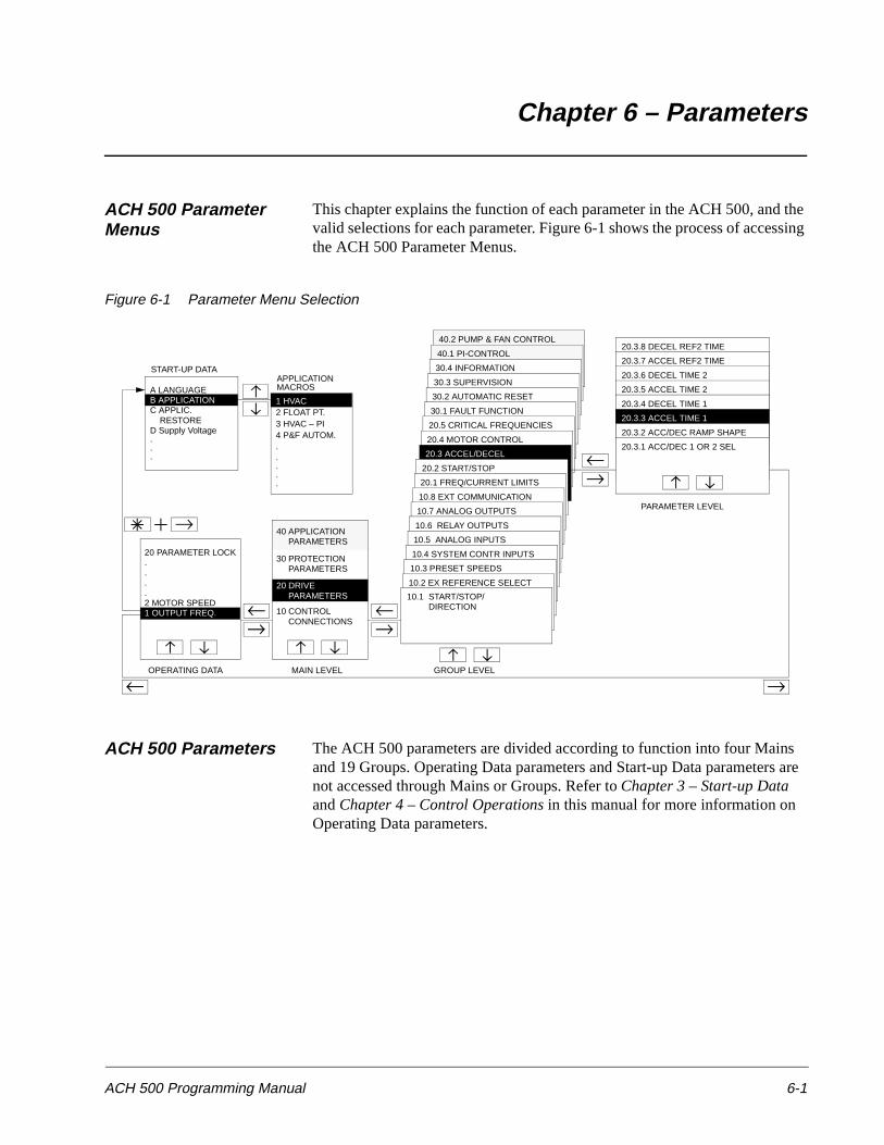
ACH 500 Programming Manual 6-1
Chapter 6 – Parameters
ACH 500 Parameter Menus
This chapter explains the function of each parameter in the ACH 500, and the valid selections for each parameter. Figure 6-1 shows the process of accessing the ACH 500 Parameter Menus.
Figure 6-1 Parameter Menu Selection
ACH 500 Parameters The ACH 500 parameters are divided according to function into four Mains and 19 Groups. Operating Data parameters and Start-up Data parameters are not accessed through Mains or Groups. Refer to Chapter 3 – Start-up Data and Chapter 4 – Control Operations in this manual for more information on Operating Data parameters.
40.2 PUMP & FAN CONTROL
40.1 PI-CONTROL
30.4 INFORMATION
30.3 SUPERVISION
30.2 AUTOMATIC RESET
30.1 FAULT FUNCTION
20.5 CRITICAL FREQUENCIES
20.4 MOTOR CONTROL
20.3 ACCEL/DECEL
20.2 START/STOP
20.1 FREQ/CURRENT LIMITS
10.8 EXT COMMUNICATION
10.7 ANALOG OUTPUTS
10.6 RELAY OUTPUTS
10.5 ANALOG INPUTS
START-UP DATA
C APPLIC. RESTORED Supply Voltage
20 PARAMETER LOCK....
30 PROTECTION PARAMETERS
10 CONTROL CONNECTIONS
10.4 SYSTEM CONTR INPUTS
10.3 PRESET SPEEDS
10.2 EX REFERENCE SELECT
10.1 START/STOP/ DIRECTION
20.3.8 DECEL REF2 TIME
20.3.7 ACCEL REF2 TIME
20.3.6 DECEL TIME 2
20.3.5 ACCEL TIME 2
20.3.4 DECEL TIME 1
20.3.3 ACCEL TIME 1
20.3.2 ACC/DEC RAMP SHAPE
20.3.1 ACC/DEC 1 OR 2 SEL
OPERATING DATA MAIN LEVEL GROUP LEVEL
PARAMETER LEVEL
1 OUTPUT FREQ.2 MOTOR SPEED
PARAMETERS20 DRIVE
A LANGUAGEAPPLICATION
1 HVAC
MACROS
2 FLOAT PT.3 HVAC – PI4 P&F AUTOM..
B APPLICATION
.
.
. ....
40 APPLICATION PARAMETERS
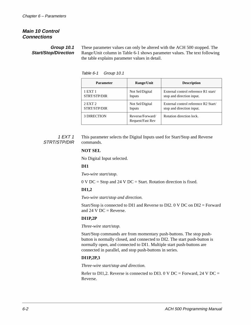
Chapter 6 – Parameters
6-2 ACH 500 Programming Manual
Main 10 Control Connections
Group 10.1Start/Stop/Direction
These parameter values can only be altered with the ACH 500 stopped. The Range/Unit column in Table 6-1 shows parameter values. The text following the table explains parameter values in detail.
Table 6-1 Group 10.1
1 EXT 1STRT/STP/DIR
This parameter selects the Digital Inputs used for Start/Stop and Reverse commands.
NOT SEL
No Digital Input selected.
DI1
Two-wire start/stop.
0 V DC = Stop and 24 V DC = Start. Rotation direction is fixed.
DI1,2
Two-wire start/stop and direction.
Start/Stop is connected to DI1 and Reverse to DI2. 0 V DC on DI2 = Forward and 24 V DC = Reverse.
DI1P,2P
Three-wire start/stop.
Start/Stop commands are from momentary push-buttons. The stop push-button is normally closed, and connected to DI2. The start push-button is normally open, and connected to DI1. Multiple start push-buttons are connected in parallel, and stop push-buttons in series.
DI1P,2P,3
Three-wire start/stop and direction.
Refer to DI1,2. Reverse is connected to DI3. 0 V DC = Forward, 24 V DC = Reverse.
Parameter Range/Unit Description
1 EXT 1STRT/STP/DIR
Not Sel/Digital Inputs
External control reference R1 start/stop and direction input.
2 EXT 2 STRT/STP/DIR
Not Sel/Digital Inputs
External control reference R2 Start/stop and direction input.
3 DIRECTION Reverse/Forward/Request/Fast Rev
Rotation direction lock.
Chapter 6 – Parameters
ACH 500 Programming Manual 6-3
DI1P,2P,3P
Start forward, start reverse, and stop.
Start and direction commands are given simultaneously with two separate momentary push-buttons. The stop push-button is normally closed, and connected to DI3. The start forward push-button is normally open, and connected to DI1. The start reverse push-button is normally open, and connected to DI2. Multiple start push-buttons are connected in parallel, and stop push-buttons in series.
DI6
Two-wire start/stop.
0 V DC = Stop and 24 V DC = Start. Rotation direction is fixed.
DI6,5
Two-wire start/stop and direction.
Start/Stop is connected to DI6 and Reverse is connected to DI5. 0 V DC on DI5 = Forward.
KEYPAD
Start/Stop command and Direction command are from the Keypad for Ext 1.
2 EXT 2 STRT/STP/DIR This parameter selects the Digital Inputs used for Start/Stop and Reverse commands. The choices are the same as Parameter 10.1.1 (Ext 1 Strt/Stp/Dir).
3 DIRECTION This parameter allows you to fix rotation direction to FORWARD or REVERSE. If you select REQUEST, the rotation direction is selected by Digital Inputs as defined in Parameters 10.1.1 (Ext 1 Strt/Stp/Dir) and 10.1.2 (Ext 2 Strt/Stp/Dir) or by keypad push-button. If FAST REV is selected, and Parameter 20.2.3 (Stop Function) is set to COAST, the modulator starts to operate in a reverse direction immediately when REVERSE is requested. This procedure results in fast reversing.
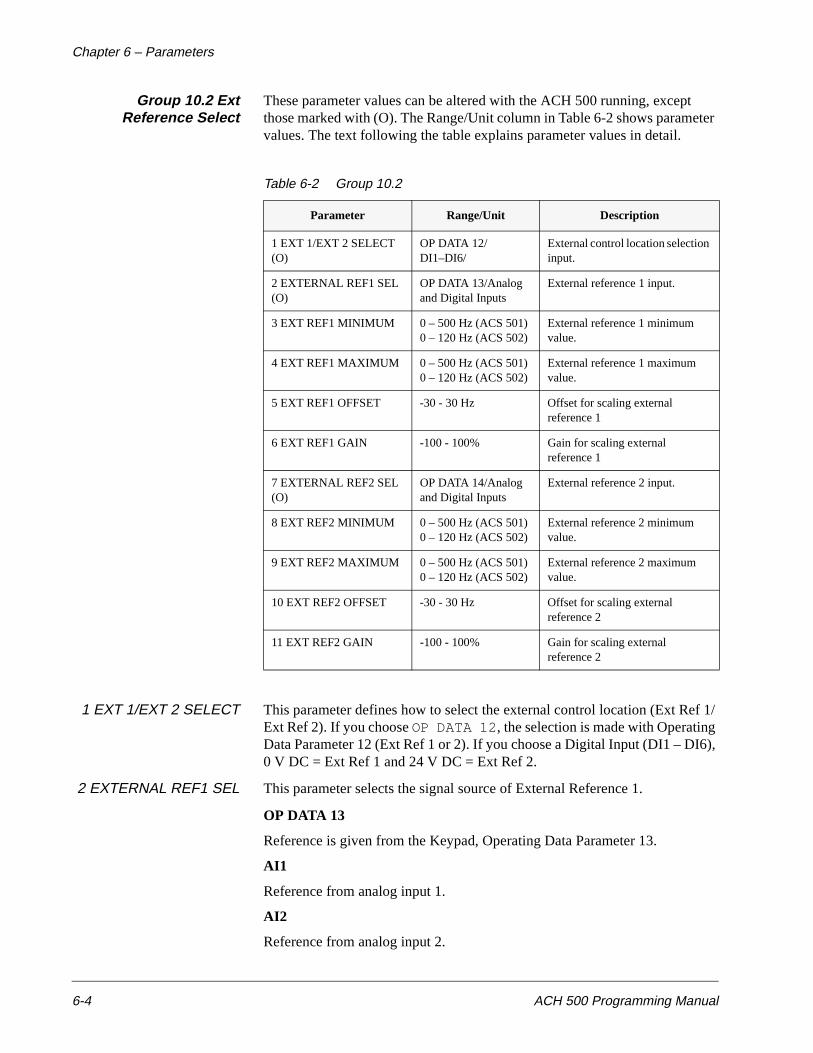
Chapter 6 – Parameters
6-4 ACH 500 Programming Manual
Group 10.2 ExtReference Select
These parameter values can be altered with the ACH 500 running, except those marked with (O). The Range/Unit column in Table 6-2 shows parameter values. The text following the table explains parameter values in detail.
Table 6-2 Group 10.2
1 EXT 1/EXT 2 SELECT This parameter defines how to select the external control location (Ext Ref 1/Ext Ref 2). If you choose OP DATA 12, the selection is made with Operating Data Parameter 12 (Ext Ref 1 or 2). If you choose a Digital Input (DI1 – DI6), 0 V DC = Ext Ref 1 and 24 V DC = Ext Ref 2.
2 EXTERNAL REF1 SEL This parameter selects the signal source of External Reference 1.
OP DATA 13
Reference is given from the Keypad, Operating Data Parameter 13.
AI1
Reference from analog input 1.
AI2
Reference from analog input 2.
Parameter Range/Unit Description
1 EXT 1/EXT 2 SELECT (O)
OP DATA 12/DI1–DI6/
External control location selection input.
2 EXTERNAL REF1 SEL (O)
OP DATA 13/Analog and Digital Inputs
External reference 1 input.
3 EXT REF1 MINIMUM 0 – 500 Hz (ACS 501) 0 – 120 Hz (ACS 502)
External reference 1 minimum value.
4 EXT REF1 MAXIMUM 0 – 500 Hz (ACS 501) 0 – 120 Hz (ACS 502)
External reference 1 maximum value.
5 EXT REF1 OFFSET -30 - 30 Hz Offset for scaling external reference 1
6 EXT REF1 GAIN -100 - 100% Gain for scaling external reference 1
7 EXTERNAL REF2 SEL (O)
OP DATA 14/Analog and Digital Inputs
External reference 2 input.
8 EXT REF2 MINIMUM 0 – 500 Hz (ACS 501) 0 – 120 Hz (ACS 502)
External reference 2 minimum value.
9 EXT REF2 MAXIMUM 0 – 500 Hz (ACS 501) 0 – 120 Hz (ACS 502)
External reference 2 maximum value.
10 EXT REF2 OFFSET -30 - 30 Hz Offset for scaling external reference 2
11 EXT REF2 GAIN -100 - 100% Gain for scaling external reference 2
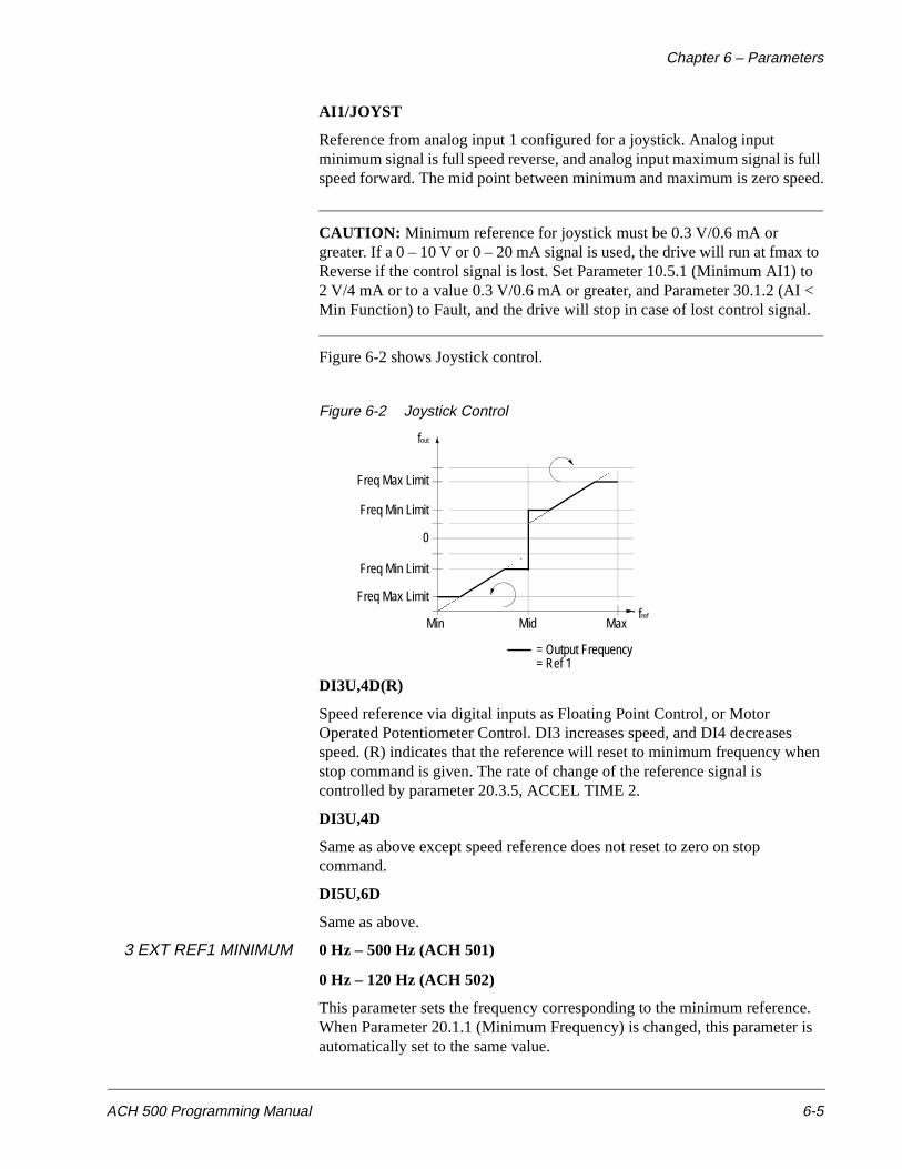
Chapter 6 – Parameters
ACH 500 Programming Manual 6-5
AI1/JOYST
Reference from analog input 1 configured for a joystick. Analog input minimum signal is full speed reverse, and analog input maximum signal is full speed forward. The mid point between minimum and maximum is zero speed.
CAUTION: Minimum reference for joystick must be 0.3 V/0.6 mA or greater. If a 0 – 10 V or 0 – 20 mA signal is used, the drive will run at fmax to Reverse if the control signal is lost. Set Parameter 10.5.1 (Minimum AI1) to 2 V/4 mA or to a value 0.3 V/0.6 mA or greater, and Parameter 30.1.2 (AI < Min Function) to Fault, and the drive will stop in case of lost control signal.
Figure 6-2 shows Joystick control.
Figure 6-2 Joystick Control
DI3U,4D(R)
Speed reference via digital inputs as Floating Point Control, or Motor Operated Potentiometer Control. DI3 increases speed, and DI4 decreases speed. (R) indicates that the reference will reset to minimum frequency when stop command is given. The rate of change of the reference signal is controlled by parameter 20.3.5, ACCEL TIME 2.
DI3U,4D
Same as above except speed reference does not reset to zero on stop command.
DI5U,6D
Same as above.
3 EXT REF1 MINIMUM 0 Hz – 500 Hz (ACH 501)
0 Hz – 120 Hz (ACH 502)
This parameter sets the frequency corresponding to the minimum reference. When Parameter 20.1.1 (Minimum Frequency) is changed, this parameter is automatically set to the same value.
Freq Max Limit
fout
Freq Min Limit
0
Freq Min Limit
Freq Max Limit
MaxMidMin
= Output Frequency= Ref 1
fref
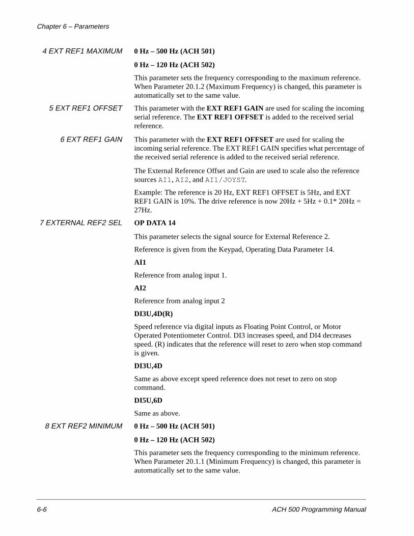
Chapter 6 – Parameters
6-6 ACH 500 Programming Manual
4 EXT REF1 MAXIMUM 0 Hz – 500 Hz (ACH 501)
0 Hz – 120 Hz (ACH 502)
This parameter sets the frequency corresponding to the maximum reference. When Parameter 20.1.2 (Maximum Frequency) is changed, this parameter is automatically set to the same value.
5 EXT REF1 OFFSET This parameter with the EXT REF1 GAIN are used for scaling the incoming serial reference. The EXT REF1 OFFSET is added to the received serial reference.
6 EXT REF1 GAIN This parameter with the EXT REF1 OFFSET are used for scaling the incoming serial reference. The EXT REF1 GAIN specifies what percentage of the received serial reference is added to the received serial reference.
The External Reference Offset and Gain are used to scale also the reference sources AI1, AI2, and AI1/JOYST.
Example: The reference is 20 Hz, EXT REF1 OFFSET is 5Hz, and EXT REF1 GAIN is 10%. The drive reference is now 20Hz + 5Hz + 0.1* 20Hz = 27Hz.
7 EXTERNAL REF2 SEL OP DATA 14
This parameter selects the signal source for External Reference 2.
Reference is given from the Keypad, Operating Data Parameter 14.
AI1
Reference from analog input 1.
AI2
Reference from analog input 2
DI3U,4D(R)
Speed reference via digital inputs as Floating Point Control, or Motor Operated Potentiometer Control. DI3 increases speed, and DI4 decreases speed. (R) indicates that the reference will reset to zero when stop command is given.
DI3U,4D
Same as above except speed reference does not reset to zero on stop command.
DI5U,6D
Same as above.
8 EXT REF2 MINIMUM 0 Hz – 500 Hz (ACH 501)
0 Hz – 120 Hz (ACH 502)
This parameter sets the frequency corresponding to the minimum reference. When Parameter 20.1.1 (Minimum Frequency) is changed, this parameter is automatically set to the same value.
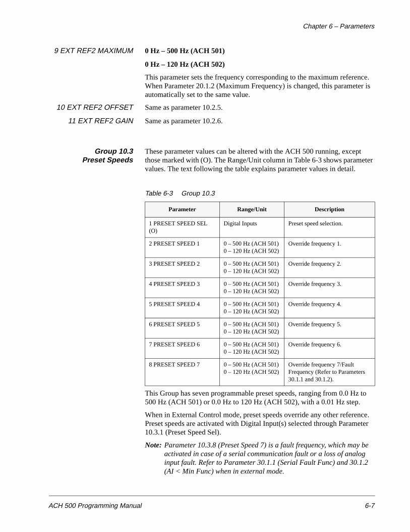
Chapter 6 – Parameters
ACH 500 Programming Manual 6-7
9 EXT REF2 MAXIMUM 0 Hz – 500 Hz (ACH 501)
0 Hz – 120 Hz (ACH 502)
This parameter sets the frequency corresponding to the maximum reference. When Parameter 20.1.2 (Maximum Frequency) is changed, this parameter is automatically set to the same value.
10 EXT REF2 OFFSET Same as parameter 10.2.5.
11 EXT REF2 GAIN Same as parameter 10.2.6.
Group 10.3Preset Speeds
These parameter values can be altered with the ACH 500 running, except those marked with (O). The Range/Unit column in Table 6-3 shows parameter values. The text following the table explains parameter values in detail.
Table 6-3 Group 10.3
This Group has seven programmable preset speeds, ranging from 0.0 Hz to 500 Hz (ACH 501) or 0.0 Hz to 120 Hz (ACH 502), with a 0.01 Hz step.
When in External Control mode, preset speeds override any other reference. Preset speeds are activated with Digital Input(s) selected through Parameter 10.3.1 (Preset Speed Sel).
Note: Parameter 10.3.8 (Preset Speed 7) is a fault frequency, which may be activated in case of a serial communication fault or a loss of analog input fault. Refer to Parameter 30.1.1 (Serial Fault Func) and 30.1.2 (AI < Min Func) when in external mode.
Parameter Range/Unit Description
1 PRESET SPEED SEL (O)
Digital Inputs Preset speed selection.
2 PRESET SPEED 1 0 – 500 Hz (ACH 501) 0 – 120 Hz (ACH 502)
Override frequency 1.
3 PRESET SPEED 2 0 – 500 Hz (ACH 501) 0 – 120 Hz (ACH 502)
Override frequency 2.
4 PRESET SPEED 3 0 – 500 Hz (ACH 501) 0 – 120 Hz (ACH 502)
Override frequency 3.
5 PRESET SPEED 4 0 – 500 Hz (ACH 501) 0 – 120 Hz (ACH 502)
Override frequency 4.
6 PRESET SPEED 5 0 – 500 Hz (ACH 501) 0 – 120 Hz (ACH 502)
Override frequency 5.
7 PRESET SPEED 6 0 – 500 Hz (ACH 501) 0 – 120 Hz (ACH 502)
Override frequency 6.
8 PRESET SPEED 7 0 – 500 Hz (ACH 501) 0 – 120 Hz (ACH 502)
Override frequency 7/Fault Frequency (Refer to Parameters 30.1.1 and 30.1.2).
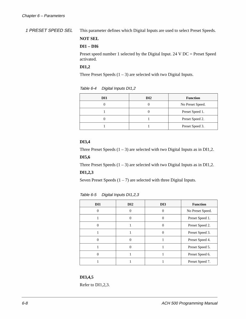
Chapter 6 – Parameters
6-8 ACH 500 Programming Manual
1 PRESET SPEED SEL This parameter defines which Digital Inputs are used to select Preset Speeds.
NOT SEL
DI1 – DI6
Preset speed number 1 selected by the Digital Input. 24 V DC = Preset Speed activated.
DI1,2
Three Preset Speeds (1 – 3) are selected with two Digital Inputs.
Table 6-4 Digital Inputs DI1,2
DI3,4
Three Preset Speeds (1 – 3) are selected with two Digital Inputs as in DI1,2.
DI5,6
Three Preset Speeds (1 – 3) are selected with two Digital Inputs as in DI1,2.
DI1,2,3
Seven Preset Speeds (1 – 7) are selected with three Digital Inputs.
Table 6-5 Digital Inputs DI1,2,3
DI3,4,5
Refer to DI1,2,3.
DI1 DI2 Function
0 0 No Preset Speed.
1 0 Preset Speed 1.
0 1 Preset Speed 2.
1 1 Preset Speed 3.
DI1 DI2 DI3 Function
0 0 0 No Preset Speed.
1 0 0 Preset Speed 1.
0 1 0 Preset Speed 2.
1 1 0 Preset Speed 3.
0 0 1 Preset Speed 4.
1 0 1 Preset Speed 5.
0 1 1 Preset Speed 6.
1 1 1 Preset Speed 7.
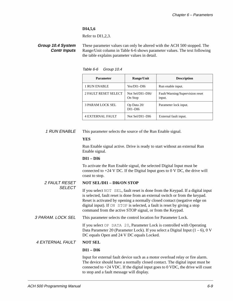
Chapter 6 – Parameters
ACH 500 Programming Manual 6-9
DI4,5,6
Refer to DI1,2,3.
Group 10.4 SystemContr Inputs
These parameter values can only be altered with the ACH 500 stopped. The Range/Unit column in Table 6-6 shows parameter values. The text following the table explains parameter values in detail.
Table 6-6 Group 10.4
1 RUN ENABLE This parameter selects the source of the Run Enable signal.
YES
Run Enable signal active. Drive is ready to start without an external Run Enable signal.
DI1 – DI6
To activate the Run Enable signal, the selected Digital Input must be connected to +24 V DC. If the Digital Input goes to 0 V DC, the drive will coast to stop.
2 FAULT RESETSELECT
NOT SEL/DI1 – DI6/ON STOP
If you select NOT SEL, fault reset is done from the Keypad. If a digital input is selected, fault reset is done from an external switch or from the keypad. Reset is activated by opening a normally closed contact (negative edge on digital input). If ON STOP is selected, a fault is reset by giving a stop command from the active STOP signal, or from the Keypad.
3 PARAM. LOCK SEL This parameter selects the control location for Parameter Lock.
If you select OP DATA 20, Parameter Lock is controlled with Operating Data Parameter 20 (Parameter Lock). If you select a Digital Input (1 – 6), 0 V DC equals Open and 24 V DC equals Locked.
4 EXTERNAL FAULT NOT SEL
DI1 – DI6
Input for external fault device such as a motor overload relay or fire alarm. The device should have a normally closed contact. The digital input must be connected to +24 VDC. If the digital input goes to 0 VDC, the drive will coast to stop and a fault message will display.
Parameter Range/Unit Description
1 RUN ENABLE Yes/DI1–DI6 Run enable input.
2 FAULT RESET SELECT Not Sel/DI1–DI6/On Stop
Fault/Warning/Supervision reset input.
3 PARAM LOCK SEL Op Data 20/DI1–DI6
Parameter lock input.
4 EXTERNAL FAULT Not Sel/DI1–DI6 External fault input.
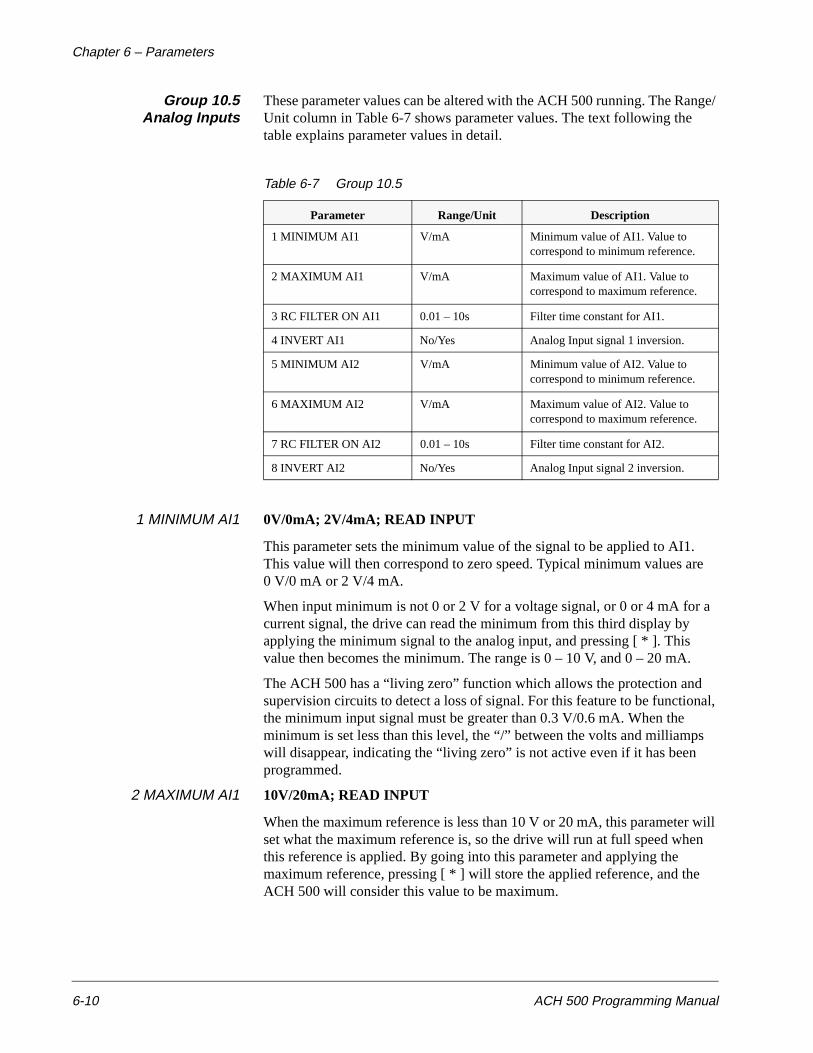
Chapter 6 – Parameters
6-10 ACH 500 Programming Manual
Group 10.5Analog Inputs
These parameter values can be altered with the ACH 500 running. The Range/ Unit column in Table 6-7 shows parameter values. The text following the table explains parameter values in detail.
Table 6-7 Group 10.5
1 MINIMUM AI1 0V/0mA; 2V/4mA; READ INPUT
This parameter sets the minimum value of the signal to be applied to AI1. This value will then correspond to zero speed. Typical minimum values are 0 V/0 mA or 2 V/4 mA.
When input minimum is not 0 or 2 V for a voltage signal, or 0 or 4 mA for a current signal, the drive can read the minimum from this third display by applying the minimum signal to the analog input, and pressing [ * ]. This value then becomes the minimum. The range is 0 – 10 V, and 0 – 20 mA.
The ACH 500 has a “living zero” function which allows the protection and supervision circuits to detect a loss of signal. For this feature to be functional, the minimum input signal must be greater than 0.3 V/0.6 mA. When the minimum is set less than this level, the “/” between the volts and milliamps will disappear, indicating the “living zero” is not active even if it has been programmed.
2 MAXIMUM AI1 10V/20mA; READ INPUT
When the maximum reference is less than 10 V or 20 mA, this parameter will set what the maximum reference is, so the drive will run at full speed when this reference is applied. By going into this parameter and applying the maximum reference, pressing [ * ] will store the applied reference, and the ACH 500 will consider this value to be maximum.
Parameter Range/Unit Description
1 MINIMUM AI1 V/mA Minimum value of AI1. Value to correspond to minimum reference.
2 MAXIMUM AI1 V/mA Maximum value of AI1. Value to correspond to maximum reference.
3 RC FILTER ON AI1 0.01 – 10s Filter time constant for AI1.
4 INVERT AI1 No/Yes Analog Input signal 1 inversion.
5 MINIMUM AI2 V/mA Minimum value of AI2. Value to correspond to minimum reference.
6 MAXIMUM AI2 V/mA Maximum value of AI2. Value to correspond to maximum reference.
7 RC FILTER ON AI2 0.01 – 10s Filter time constant for AI2.
8 INVERT AI2 No/Yes Analog Input signal 2 inversion.
Chapter 6 – Parameters
ACH 500 Programming Manual 6-11
3 RC FILTER ON AI1 Filter time constant for Analog Input 1.
As the Analog Input value changes, 63 percent of the change takes place within the time period given by this parameter. If you select the minimum value 0.01s, the signal is not filtered.
Figure 6-3 shows filter time constant.
Figure 6-3 Filter Time Constant
4 INVERT AI1 NO/YES
If this parameter is set to YES, maximum reference gives minimum frequency and minimum reference gives maximum frequency.
5 MINIMUM AI2 Refer to Parameter 10.5.1.
6 MAXIMUM AI2 Refer to Parameter 10.5.2.
7 RC FILTER ON AI2 Refer to Parameter 10.5.3.
8 INVERT AI2 Refer to Parameter 10.5.4.
63
[%]
100
Filter AI1t
Filtered Signal
Unfiltered Signal
Chapter 6 – Parameters
6-12 ACH 500 Programming Manual
Group 10.6Relay Outputs
These parameter values can only be altered when the ACH 500 is not running. The text following Table 6-8 explains parameter values in detail.
Table 6-8 Group 10.6
1 RELAY RO1 OUTPUT This parameter allows you to select which information is indicated with Relay Output 1.
READYThe ACS 500 is ready to function. The relay is energized unless no run enable is present or a fault exists.
RUNThe drive has been started, has an enable signal, and is not in a fault trip.
FAULTAny fault occurs. Refer to Chapter 5 – Fault Tracing in the Installation & Start-up Manual for more details.
FAULT (-1)Relay energizes when power is applied, and de-energizes upon a fault trip.
FAULT(RST)The ACS 500 is in a fault condition, but will reset after the programmed autoreset delay.
STALL FLTStall protection has tripped.
MOT OT FLTMotor overload (I2t) protection has tripped.
OT FAULTThe ACS 500 overheat protection has tripped. The tripping level is 158°F (70°C) for ACS 501 and 185°F (85°C) for ACS 502.
FAULT/WARNAny fault or warning has occurred.
WARNINGAny warning has occurred.
OT WARNINGThe heatsink temperature has exceeded the warning level 149°F (65°C).
REVERSEDReverse is selected.
Parameter Range/Unit Description
1 RELAY RO1 OUTPUT Refer to the text below for the available selections.
Relay Output 1 content.
2 RELAY RO2 OUTPUT Relay Output 2 content.
3 RELAY RO3 OUTPUT Relay Output 3 content.
Chapter 6 – Parameters
ACH 500 Programming Manual 6-13
EXT. CTRLExternal control selected.
REF 2 SELReference 2 selected.
PRESET SPDA Preset Speed (1 – 7) selected.
DC BUS LIMVoltage regulator is activated.
FREQ1 LIMOutput frequency has exceeded the Supervision Limit 1. Refer to Parameter 30.3.1 (Output Freq 1 Func).
FREQ2 LIMOutput frequency has exceeded the Supervision Limit 2. Refer to Parameter 30.3.4 (Output Freq 2 Lim).
CURRENT LIMITMotor current has exceeded the set Current Supervision Limit. Refer to Parameter 30.3.6 (Current Limit).
REF 1 LIMITReference 1 has exceeded the set Supervision Limit. Refer to Parameter 30.3.8 (Ref 1 Limit).
REF 2 LIMITReference 2 has exceeded the set Supervision Limit. Refer to Parameter 30.3.10 (Ref 2 Limit).
AT SPEEDThe output frequency is equal to the set frequency (+/- .25 Hz of set frequency).
HIGH TEMPHigh heatsink temperature indication with hysteresis. Relay activates at 60°C (140°F), and opens at 40°C (104°F).
P&F AUTOM
When Pump and Fan macro is selected, some relays are automatically reserved for the lag pumps. When a relay is reserved for Pump and Fan sequencing, P&F AUTOM will appear in this parameter.
2 RELAY RO2 OUTPUT Refer to Parameter 10.6.1 (Relay RO1 Output).
3 RELAY RO3 OUTPUT Refer to Parameter 10.6.1 (Relay RO1 Output).
Chapter 6 – Parameters
6-14 ACH 500 Programming Manual
Group 10.7 AnalogOutputs
These parameter values can be altered with the ACH 500 running, except those marked with (O). The Range/Unit column in Table 6-9 shows parameter values. The text following the table explains parameter values in detail.
Table 6-9 Group 10.7
1 ANALOG OUTPUT 1 This Parameter allows you to select which output signal is connected to Analog Output 1 (current signal). The following list shows the full scale reading with Parameters 10.7.2 (Scale AO1) and 10.7.7 (Scale AO2) set to 100%.
NOT USED
OUT FREQ
Output frequency. 20 mA = 60 Hz.
MOT SPEED
Motor speed. 20 mA = motor speed at 60 Hz.
OUT CURR
Output current. 20 mA = motor nominal current.
MOT TORQ
Motor torque. 20 mA = 100% of motor nominal rating.
MOT POWER
Motor power. 20 mA = 100% of motor nominal rating.
Parameter Range/Unit Description
1 ANALOG OUTPUT 1 (O)
Refer to the text below for the available selections.
Analog Output 1 content.
2 SCALE AO1 10 – 1000% Analog Output signal 1 scaling factor.
3 MINIMUM AO1 0 mA/4 mA Analog Output signal 1 minimum.
4 RC FILTER ON AO1 0.01 – 10s Filter time constant for AO1.
5 INVERT AO1 NO/YES Analog Output signal 1 inversion.
6 ANALOG OUTPUT 2 (O)
Refer to the text below for the available selections.
Analog Output 2 content.
7 SCALE AO2 10 – 1000% Analog Output signal 2 scaling factor.
8 MINIMUM AO2 0 mA/4 mA Analog Output signal 2 minimum.
9 RC FILTER ON AO2 0.01 – 10s Filter time constant for AO2.
10 INVERT AO2 NO/YES Analog Output signal 2 inversion.
Chapter 6 – Parameters
ACH 500 Programming Manual 6-15
V/DC BUS
DC bus voltage. 20 mA = 100% of Nominal DC Bus Voltage (VN x 1.35).
MOTOR VOLT
Motor voltage. 20 mA = Supply Voltage.
REFERENCE
Active reference that the ACH 500 is currently following. 20 mA = 100% of the active reference.
The following can only be seen when the Pump & Fan macro is selected.
ERROR VAL
Scaled difference of ACT and REF values.
PICON OUTP
PI regulator output.
ACTUAL 1
Unscaled actual value 1.
ACTUAL 2
Unscaled actual value 2.
PICON REF
Reference of PI-Controller.
2 SCALE AO1 This parameter is the scaling factor for the Analog Output 1 signal. If you select 100%, the nominal value of the output signal corresponds to 20 mA. If the maximum is less than full scale, increase the value of this parameter.
3 MINIMUM AO1 The minimum value of the Analog Output signal can be set to either 0 mA or 4 mA.
4 RC FILTER ON AO1 Filter time constant for Analog Output 1.
As Analog Output value changes, 63 percent of the change takes place within the time period given by this parameter. If you select the minimum value 0.01s, the signal is not filtered. (See Figure 6-3 for Parameter 10.7.4).
5 INVERT AO1 If you select YES, the Analog Output 1 signal is inverted.
6 ANALOG OUTPUT 2 Refer to Parameter 10.7.1.
7 SCALE AO2 Refer to Parameter 10.7.2.
8 MINIMUM AO2 Refer to Parameter 10.7.3.
9 RC FILTER ON AO2 Refer to Parameter 10.7.4.
10 INVERT AO2 Refer to Parameter 10.7.5.
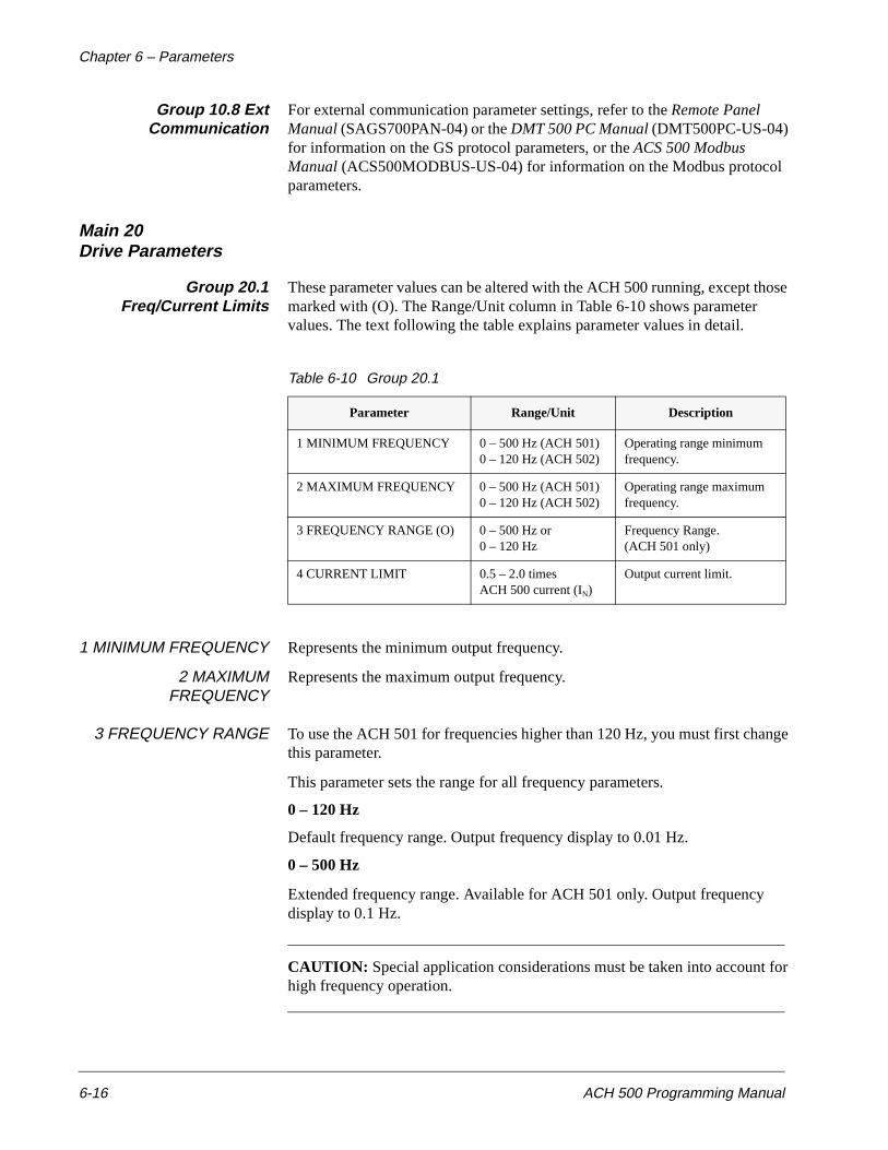
Chapter 6 – Parameters
6-16 ACH 500 Programming Manual
Group 10.8 ExtCommunication
For external communication parameter settings, refer to the Remote Panel Manual (SAGS700PAN-04) or the DMT 500 PC Manual (DMT500PC-US-04) for information on the GS protocol parameters, or the ACS 500 Modbus Manual (ACS500MODBUS-US-04) for information on the Modbus protocol parameters.
Main 20Drive Parameters
Group 20.1Freq/Current Limits
These parameter values can be altered with the ACH 500 running, except those marked with (O). The Range/Unit column in Table 6-10 shows parameter values. The text following the table explains parameter values in detail.
Table 6-10 Group 20.1
1 MINIMUM FREQUENCY Represents the minimum output frequency.
2 MAXIMUMFREQUENCY
Represents the maximum output frequency.
3 FREQUENCY RANGE To use the ACH 501 for frequencies higher than 120 Hz, you must first change this parameter.
This parameter sets the range for all frequency parameters.
0 – 120 Hz
Default frequency range. Output frequency display to 0.01 Hz.
0 – 500 Hz
Extended frequency range. Available for ACH 501 only. Output frequency display to 0.1 Hz.
CAUTION: Special application considerations must be taken into account for high frequency operation.
Parameter Range/Unit Description
1 MINIMUM FREQUENCY 0 – 500 Hz (ACH 501) 0 – 120 Hz (ACH 502)
Operating range minimum frequency.
2 MAXIMUM FREQUENCY 0 – 500 Hz (ACH 501) 0 – 120 Hz (ACH 502)
Operating range maximum frequency.
3 FREQUENCY RANGE (O) 0 – 500 Hz or0 – 120 Hz
Frequency Range.(ACH 501 only)
4 CURRENT LIMIT 0.5 – 2.0 times ACH 500 current (IN)
Output current limit.
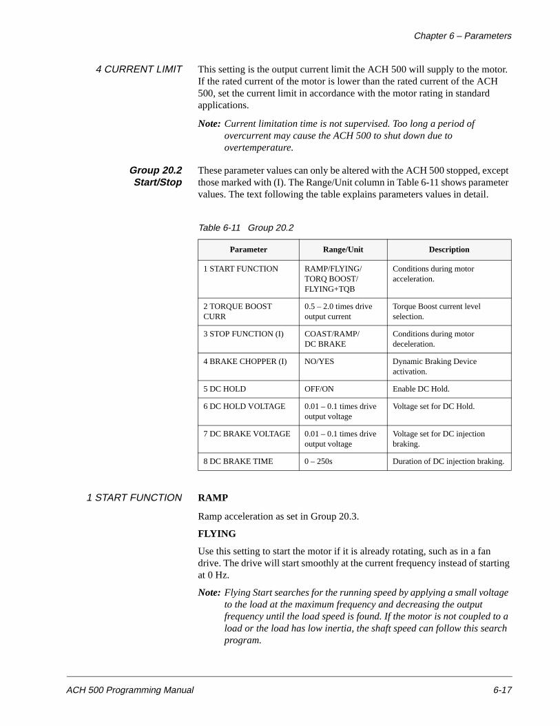
Chapter 6 – Parameters
ACH 500 Programming Manual 6-17
4 CURRENT LIMIT This setting is the output current limit the ACH 500 will supply to the motor. If the rated current of the motor is lower than the rated current of the ACH 500, set the current limit in accordance with the motor rating in standard applications.
Note: Current limitation time is not supervised. Too long a period of overcurrent may cause the ACH 500 to shut down due to overtemperature.
Group 20.2Start/Stop
These parameter values can only be altered with the ACH 500 stopped, except those marked with (I). The Range/Unit column in Table 6-11 shows parameter values. The text following the table explains parameters values in detail.
Table 6-11 Group 20.2
1 START FUNCTION RAMP
Ramp acceleration as set in Group 20.3.
FLYING
Use this setting to start the motor if it is already rotating, such as in a fan drive. The drive will start smoothly at the current frequency instead of starting at 0 Hz.
Note: Flying Start searches for the running speed by applying a small voltage to the load at the maximum frequency and decreasing the output frequency until the load speed is found. If the motor is not coupled to a load or the load has low inertia, the shaft speed can follow this search program.
Parameter Range/Unit Description
1 START FUNCTION RAMP/FLYING/TORQ BOOST/FLYING+TQB
Conditions during motor acceleration.
2 TORQUE BOOST CURR
0.5 – 2.0 times drive output current
Torque Boost current level selection.
3 STOP FUNCTION (I) COAST/RAMP/DC BRAKE
Conditions during motor deceleration.
4 BRAKE CHOPPER (I) NO/YES Dynamic Braking Device activation.
5 DC HOLD OFF/ON Enable DC Hold.
6 DC HOLD VOLTAGE 0.01 – 0.1 times drive output voltage
Voltage set for DC Hold.
7 DC BRAKE VOLTAGE 0.01 – 0.1 times drive output voltage
Voltage set for DC injection braking.
8 DC BRAKE TIME 0 – 250s Duration of DC injection braking.
Chapter 6 – Parameters
6-18 ACH 500 Programming Manual
TORQ BOOST
Automatic start current boost, which may be necessary in applications requiring high starting torque. Automatic torque boost is active only from 0 Hz to 20 Hz or until the reference speed is reached. Torque boost is not activated if the output frequency falls below 20 Hz while running.
Refer to IR Compensation in Group 20.4 for added torque at low speeds while running.
FLYING + TQB
Both Flying Start and Torque Boost functions are active.
2 TORQUE BOOST CUR Sets the current that will be allowed when Torque Boost start is selected. Keep the boost current as low as possible for the application. Setting is in actual amps, 0.5 – 2.0 x IN, 1% step.
3 STOP FUNCTION COAST
The ACH 500 AC drive stops supplying voltage immediately after stop command is received and the motor coasts to a stop.
RAMP
Ramp deceleration as set in Group 20.3.
DC BRAKE
DC injection braking stops the motor by applying DC to the stator windings. By using DC braking, the motor can be stopped in the shortest possible time, outside of using a dynamic braking device.
Note: If the Run Enable input is deactivated, the ACH 500 will stop by coasting, regardless of the Stop Function setting.
4 BRAKE CHOPPER If a dynamic braking device is used, the Decel Limit level (voltage regulator upper limit) can be increased by selecting YES for this parameter. Decel Limit level is raised to within five percent of the Overvoltage Trip point, essentially eliminating the Decel Limit.
5 DC HOLD If this parameter is set to YES, the DC Hold feature is enabled.
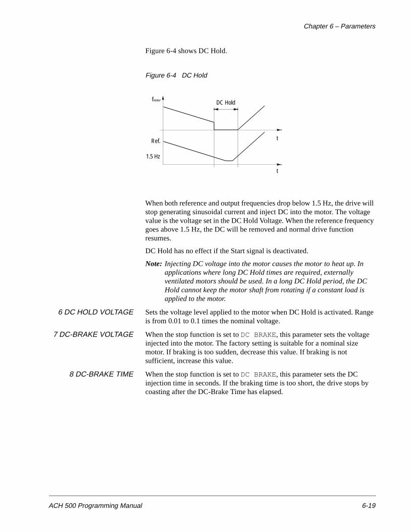
Chapter 6 – Parameters
ACH 500 Programming Manual 6-19
Figure 6-4 shows DC Hold.
Figure 6-4 DC Hold
When both reference and output frequencies drop below 1.5 Hz, the drive will stop generating sinusoidal current and inject DC into the motor. The voltage value is the voltage set in the DC Hold Voltage. When the reference frequency goes above 1.5 Hz, the DC will be removed and normal drive function resumes.
DC Hold has no effect if the Start signal is deactivated.
Note: Injecting DC voltage into the motor causes the motor to heat up. In applications where long DC Hold times are required, externally ventilated motors should be used. In a long DC Hold period, the DC Hold cannot keep the motor shaft from rotating if a constant load is applied to the motor.
6 DC HOLD VOLTAGE Sets the voltage level applied to the motor when DC Hold is activated. Range is from 0.01 to 0.1 times the nominal voltage.
7 DC-BRAKE VOLTAGE When the stop function is set to DC BRAKE, this parameter sets the voltage injected into the motor. The factory setting is suitable for a nominal size motor. If braking is too sudden, decrease this value. If braking is not sufficient, increase this value.
8 DC-BRAKE TIME When the stop function is set to DC BRAKE, this parameter sets the DC injection time in seconds. If the braking time is too short, the drive stops by coasting after the DC-Brake Time has elapsed.
1.5 Hz
t
t
fmotor
Ref.
DC Hold
Chapter 6 – Parameters
6-20 ACH 500 Programming Manual
Group 20.3Accel/Decel
These parameter values can be altered with the ACH 500 running, except those marked with (O). The Range/Unit column in Table 6-12 shows parameter values. The text following the table explains parameter values in detail.
Table 6-12 Group 20.3
1 ACC/DEC 1OR2 SEL This parameter defines which Digital Input (1 – 6) is used to select the Acceleration/Deceleration Ramp used. 0 V DC equals Acc/Dec Time 1, 24 V DC equals Acc/Dec Time 2.
2 ACC/DECRAMP SHAPE
This parameter allows you to select the shape of the acceleration/deceleration ramp. The available options are:
LINEAR
Suitable for drives requiring steady acceleration/deceleration and/or slow ramps.
S1 SHAPE
Suitable for ramp times less than one second.
S2 SHAPE
Suitable for ramp times less than 1.5 seconds.
S3 SHAPE
Suitable for ramp times up to 15 seconds.
Figure 6-5 shows acceleration and deceleration ramp shapes.
Parameter Range/Unit Description
1 ACC/DEC 1OR2 SEL (O) Not Sel/DI1–DI6
Acceleration/Deceleration ramp selection.
2 ACC/DEC RAMP SHAPE Linear/S1 – S3 Accel./Decel. ramp shape selection.
3 ACCEL TIME 1 0.1 – 1800s Time for output frequency min. to max. acceleration ramp 1.
4 DECEL TIME 1 0.1 – 1800s Time for output frequency max. to min. deceleration ramp 1.
5 ACCEL TIME 2 0.1 – 1800s Time for output frequency min. to max. acceleration ramp 2.
6 DECEL TIME 2 0.1 – 1800s Time for output frequency max. to min. deceleration ramp 2.
7 ACCEL REF2 TIME 0.1 – 1800s Ref2 acceleration ramp time for 0 – 100%.
8 DECEL REF2 TIME 0.1 – 1800s Ref2 deceleration ramp time for 100 – 0%.
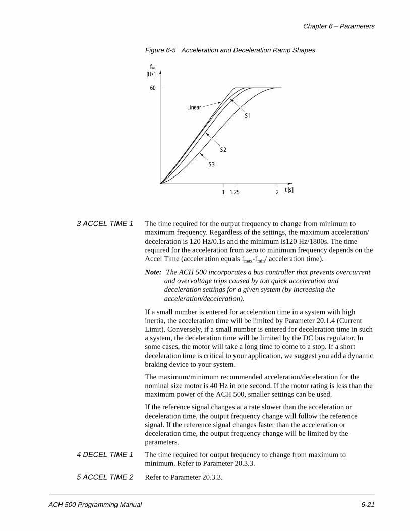
Chapter 6 – Parameters
ACH 500 Programming Manual 6-21
Figure 6-5 Acceleration and Deceleration Ramp Shapes
3 ACCEL TIME 1 The time required for the output frequency to change from minimum to maximum frequency. Regardless of the settings, the maximum acceleration/deceleration is 120 Hz/0.1s and the minimum is120 Hz/1800s. The time required for the acceleration from zero to minimum frequency depends on the Accel Time (acceleration equals fmax-fmin/ acceleration time).
Note: The ACH 500 incorporates a bus controller that prevents overcurrent and overvoltage trips caused by too quick acceleration and deceleration settings for a given system (by increasing the acceleration/deceleration).
If a small number is entered for acceleration time in a system with high inertia, the acceleration time will be limited by Parameter 20.1.4 (Current Limit). Conversely, if a small number is entered for deceleration time in such a system, the deceleration time will be limited by the DC bus regulator. In some cases, the motor will take a long time to come to a stop. If a short deceleration time is critical to your application, we suggest you add a dynamic braking device to your system.
The maximum/minimum recommended acceleration/deceleration for the nominal size motor is 40 Hz in one second. If the motor rating is less than the maximum power of the ACH 500, smaller settings can be used.
If the reference signal changes at a rate slower than the acceleration or deceleration time, the output frequency change will follow the reference signal. If the reference signal changes faster than the acceleration or deceleration time, the output frequency change will be limited by the parameters.
4 DECEL TIME 1 The time required for output frequency to change from maximum to minimum. Refer to Parameter 20.3.3.
5 ACCEL TIME 2 Refer to Parameter 20.3.3.
S2
S3
LinearS1
60
[Hz]
1 t [s]
fout
1.25 2
Chapter 6 – Parameters
6-22 ACH 500 Programming Manual
6 DECEL TIME 2 Refer to Parameter 20.3.4.
7 ACCEL REF2 TIME Corresponds to the time required for the reference to change from 0 to 100 percent and vice versa, if the PI-Controller is not used.
8 DECEL REF2 TIME Refer to Parameter 20.3.7.
Group 20.4Motor Control
These parameter values can only be altered with the ACH 500 stopped, except those marked with (I). The Range/Unit column in Table 6-13 shows parameter values. The text following the table explains parameter values in detail.
Table 6-13 Group 20.4
Parameter Range/Unit Description
1 SWITCHING FREQ 1.0 – 12.0 kHz (ACH 501)3.0 kHz (ACH 502)
Carrier frequency selection.
2 MAX OUT VOLTAGE 0.15 – 1.05 times drive output voltage
Maximum motor voltage selection.
3 V/Hz RATIO LINEAR/SQUARED/AUTOMATIC
Voltage to frequency relationship in region below Field Weakening Point.
4 FIELD WEAK POINT 30 – 500 Hz Threshold for nominal voltage.
5 IR COMPENSATION NO/MANUAL/AUTOMATIC
Low speed torque boost function.
6 IR COMP VOLTAGE 0.01 – 0.15 times drive output voltage
Voltage level in manual IR Compensation.
7 IR COMP RANGE 0 Hz – FWP Zero point in manual IR Compensation.
8 SLIP COMPENSATION (I)
OFF/ON Automatic slip reduction.
9 NOMINAL SLIP (I) 0.1 – 10% Nominal slip of the motor.
10 VOLTAGE LIMIT (I) OFF/ON Over-/Undervoltage Controller.
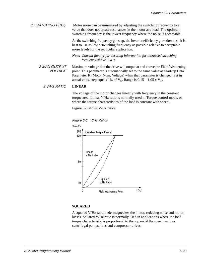
Chapter 6 – Parameters
ACH 500 Programming Manual 6-23
1 SWITCHING FREQ Motor noise can be minimized by adjusting the switching frequency to a value that does not create resonances in the motor and load. The optimum switching frequency is the lowest frequency where the noise is acceptable.
As the switching frequency goes up, the inverter efficiency goes down, so it is best to use as low a switching frequency as possible relative to acceptable noise levels for the particular application.
Note: Consult factory for derating information for increased switching frequency above 3 kHz.
2 MAX OUTPUTVOLTAGE
Maximum voltage that the drive will output at and above the Field Weakening point. This parameter is automatically set to the same value as Start-up Data Parameter K (Motor Nom. Voltage) when that parameter is changed. Set in actual volts, step equals 1% of VN. Range is 0.15 – 1.05 x VN.
3 V/Hz RATIO LINEAR
The voltage of the motor changes linearly with frequency in the constant torque area. Linear V/Hz ratio is normally used in Torque control mode, or where the torque characteristics of the load is constant with speed.
Figure 6-6 shows V/Hz ratios.
Figure 6-6 V/Hz Ratios
SQUARED
A squared V/Hz ratio undermagnetizes the motor, reducing noise and motor losses. Squared V/Hz ratio is normally used in applications where the load torque characteristic is proportional to the square of the speed, such as centrifugal pumps, fans and compressor drives.
f [Hz]0
Constant Torque Range
10
50
100[%]
VMAX /VN
LinearV/Hz Ratio
SquaredV/Hz Ratio
Field Weakening Point
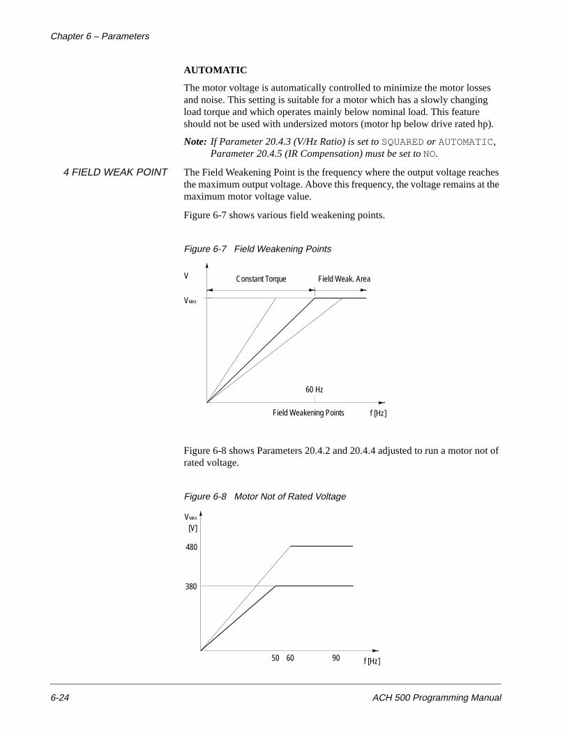
Chapter 6 – Parameters
6-24 ACH 500 Programming Manual
AUTOMATIC
The motor voltage is automatically controlled to minimize the motor losses and noise. This setting is suitable for a motor which has a slowly changing load torque and which operates mainly below nominal load. This feature should not be used with undersized motors (motor hp below drive rated hp).
Note: If Parameter 20.4.3 (V/Hz Ratio) is set to SQUARED or AUTOMATIC, Parameter 20.4.5 (IR Compensation) must be set to NO.
4 FIELD WEAK POINT The Field Weakening Point is the frequency where the output voltage reaches the maximum output voltage. Above this frequency, the voltage remains at the maximum motor voltage value.
Figure 6-7 shows various field weakening points.
Figure 6-7 Field Weakening Points
Figure 6-8 shows Parameters 20.4.2 and 20.4.4 adjusted to run a motor not of rated voltage.
Figure 6-8 Motor Not of Rated Voltage
Field Weakening Points f [Hz]
60 Hz
Constant Torque Field Weak. AreaV
VMAX
f [Hz]60
480
VMAX
380
50 90
[V]
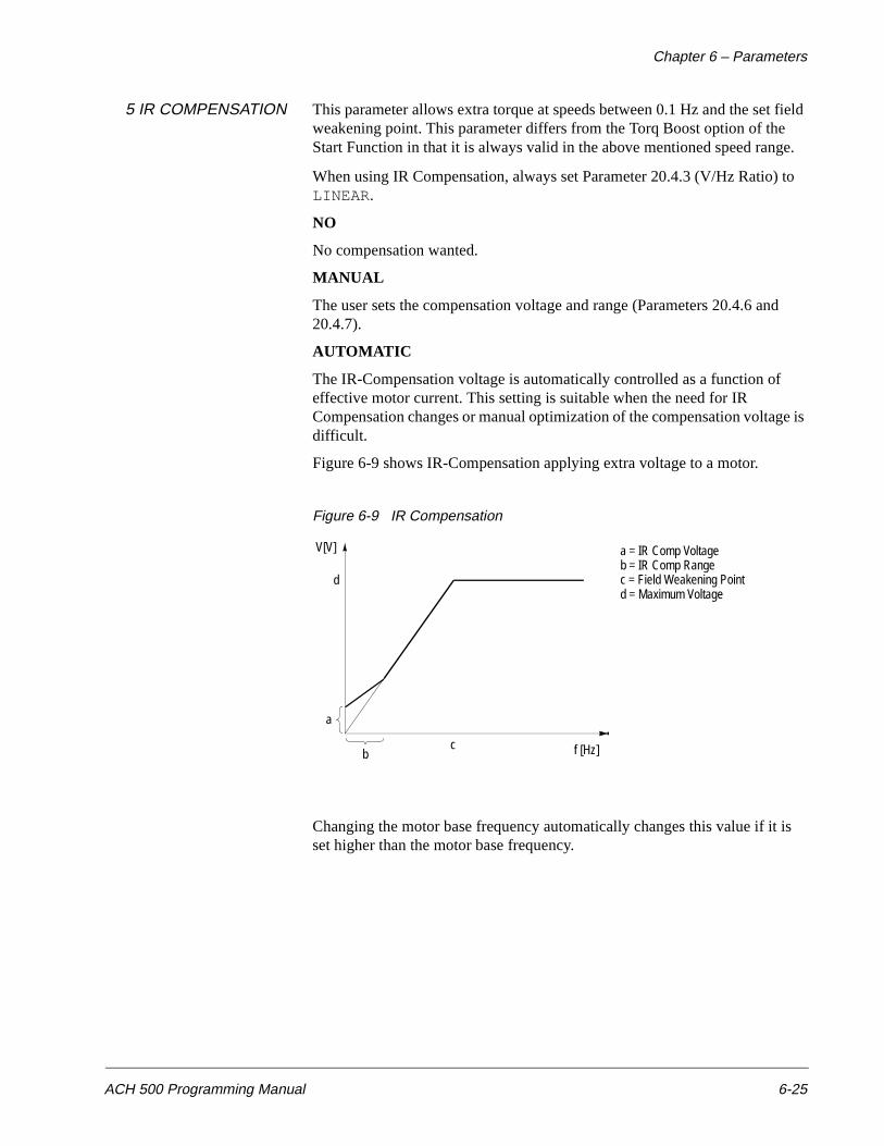
Chapter 6 – Parameters
ACH 500 Programming Manual 6-25
5 IR COMPENSATION This parameter allows extra torque at speeds between 0.1 Hz and the set field weakening point. This parameter differs from the Torq Boost option of the Start Function in that it is always valid in the above mentioned speed range.
When using IR Compensation, always set Parameter 20.4.3 (V/Hz Ratio) to LINEAR.
NO
No compensation wanted.
MANUAL
The user sets the compensation voltage and range (Parameters 20.4.6 and 20.4.7).
AUTOMATIC
The IR-Compensation voltage is automatically controlled as a function of effective motor current. This setting is suitable when the need for IR Compensation changes or manual optimization of the compensation voltage is difficult.
Figure 6-9 shows IR-Compensation applying extra voltage to a motor.
Figure 6-9 IR Compensation
Changing the motor base frequency automatically changes this value if it is set higher than the motor base frequency.
f [Hz]
d
c
V[V]
b
a
a = IR Comp Voltageb = IR Comp Rangec = Field Weakening Pointd = Maximum Voltage
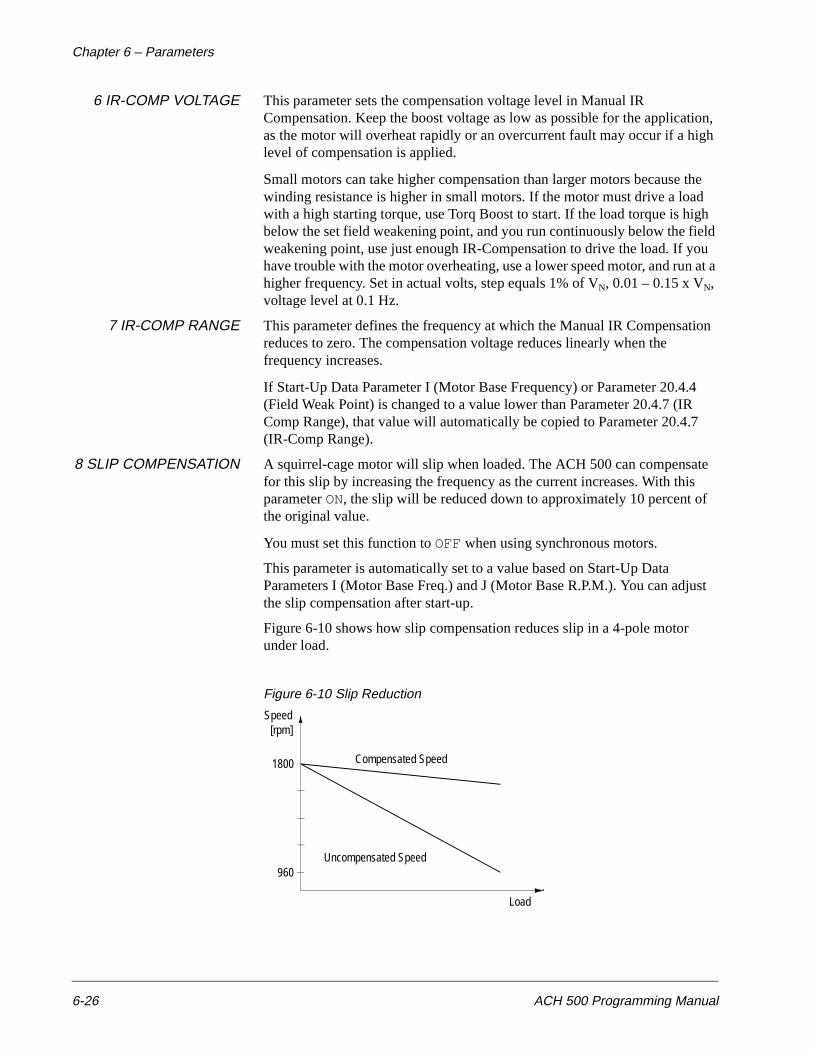
Chapter 6 – Parameters
6-26 ACH 500 Programming Manual
6 IR-COMP VOLTAGE This parameter sets the compensation voltage level in Manual IR Compensation. Keep the boost voltage as low as possible for the application, as the motor will overheat rapidly or an overcurrent fault may occur if a high level of compensation is applied.
Small motors can take higher compensation than larger motors because the winding resistance is higher in small motors. If the motor must drive a load with a high starting torque, use Torq Boost to start. If the load torque is high below the set field weakening point, and you run continuously below the field weakening point, use just enough IR-Compensation to drive the load. If you have trouble with the motor overheating, use a lower speed motor, and run at a higher frequency. Set in actual volts, step equals 1% of VN, 0.01 – 0.15 x VN, voltage level at 0.1 Hz.
7 IR-COMP RANGE This parameter defines the frequency at which the Manual IR Compensation reduces to zero. The compensation voltage reduces linearly when the frequency increases.
If Start-Up Data Parameter I (Motor Base Frequency) or Parameter 20.4.4 (Field Weak Point) is changed to a value lower than Parameter 20.4.7 (IR Comp Range), that value will automatically be copied to Parameter 20.4.7 (IR-Comp Range).
8 SLIP COMPENSATION A squirrel-cage motor will slip when loaded. The ACH 500 can compensate for this slip by increasing the frequency as the current increases. With this parameter ON, the slip will be reduced down to approximately 10 percent of the original value.
You must set this function to OFF when using synchronous motors.
This parameter is automatically set to a value based on Start-Up Data Parameters I (Motor Base Freq.) and J (Motor Base R.P.M.). You can adjust the slip compensation after start-up.
Figure 6-10 shows how slip compensation reduces slip in a 4-pole motor under load.
Figure 6-10 Slip Reduction
Load
1800
[rpm]Speed
960Uncompensated Speed
Compensated Speed
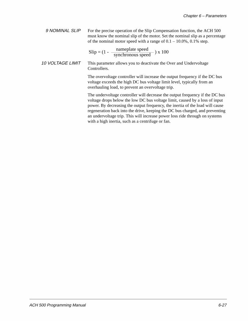
Chapter 6 – Parameters
ACH 500 Programming Manual 6-27
9 NOMINAL SLIP For the precise operation of the Slip Compensation function, the ACH 500 must know the nominal slip of the motor. Set the nominal slip as a percentage of the nominal motor speed with a range of 0.1 – 10.0%, 0.1% step.
10 VOLTAGE LIMIT This parameter allows you to deactivate the Over and Undervoltage Controllers.
The overvoltage controller will increase the output frequency if the DC bus voltage exceeds the high DC bus voltage limit level, typically from an overhauling load, to prevent an overvoltage trip.
The undervoltage controller will decrease the output frequency if the DC bus voltage drops below the low DC bus voltage limit, caused by a loss of input power. By decreasing the output frequency, the inertia of the load will cause regeneration back into the drive, keeping the DC bus charged, and preventing an undervoltage trip. This will increase power loss ride through on systems with a high inertia, such as a centrifuge or fan.
Slip = (1 - synchronous speednameplate speed
) x 100
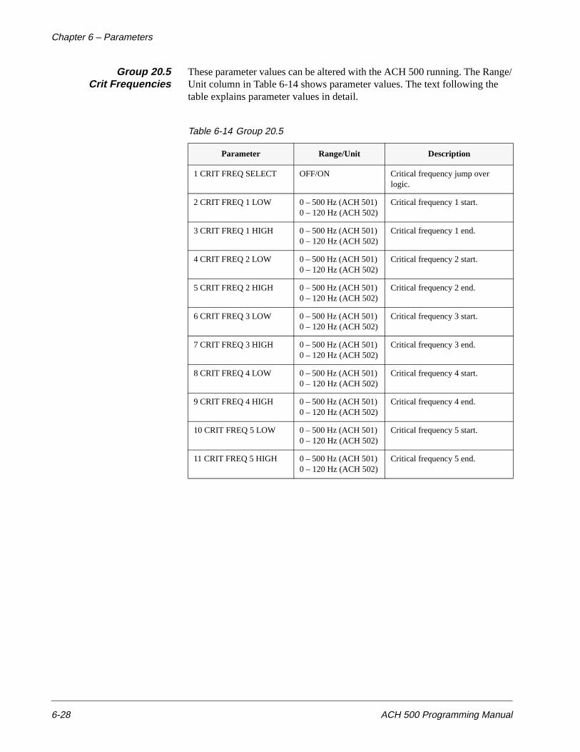
Chapter 6 – Parameters
6-28 ACH 500 Programming Manual
Group 20.5Crit Frequencies
These parameter values can be altered with the ACH 500 running. The Range/Unit column in Table 6-14 shows parameter values. The text following the table explains parameter values in detail.
Table 6-14 Group 20.5
Parameter Range/Unit Description
1 CRIT FREQ SELECT OFF/ON Critical frequency jump over logic.
2 CRIT FREQ 1 LOW 0 – 500 Hz (ACH 501) 0 – 120 Hz (ACH 502)
Critical frequency 1 start.
3 CRIT FREQ 1 HIGH 0 – 500 Hz (ACH 501) 0 – 120 Hz (ACH 502)
Critical frequency 1 end.
4 CRIT FREQ 2 LOW 0 – 500 Hz (ACH 501) 0 – 120 Hz (ACH 502)
Critical frequency 2 start.
5 CRIT FREQ 2 HIGH 0 – 500 Hz (ACH 501) 0 – 120 Hz (ACH 502)
Critical frequency 2 end.
6 CRIT FREQ 3 LOW 0 – 500 Hz (ACH 501) 0 – 120 Hz (ACH 502)
Critical frequency 3 start.
7 CRIT FREQ 3 HIGH 0 – 500 Hz (ACH 501) 0 – 120 Hz (ACH 502)
Critical frequency 3 end.
8 CRIT FREQ 4 LOW 0 – 500 Hz (ACH 501) 0 – 120 Hz (ACH 502)
Critical frequency 4 start.
9 CRIT FREQ 4 HIGH 0 – 500 Hz (ACH 501) 0 – 120 Hz (ACH 502)
Critical frequency 4 end.
10 CRIT FREQ 5 LOW 0 – 500 Hz (ACH 501) 0 – 120 Hz (ACH 502)
Critical frequency 5 start.
11 CRIT FREQ 5 HIGH 0 – 500 Hz (ACH 501) 0 – 120 Hz (ACH 502)
Critical frequency 5 end.
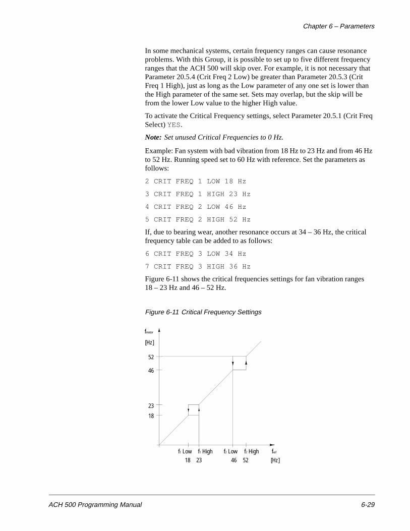
Chapter 6 – Parameters
ACH 500 Programming Manual 6-29
In some mechanical systems, certain frequency ranges can cause resonance problems. With this Group, it is possible to set up to five different frequency ranges that the ACH 500 will skip over. For example, it is not necessary that Parameter 20.5.4 (Crit Freq 2 Low) be greater than Parameter 20.5.3 (Crit Freq 1 High), just as long as the Low parameter of any one set is lower than the High parameter of the same set. Sets may overlap, but the skip will be from the lower Low value to the higher High value.
To activate the Critical Frequency settings, select Parameter 20.5.1 (Crit Freq Select) YES.
Note: Set unused Critical Frequencies to 0 Hz.
Example: Fan system with bad vibration from 18 Hz to 23 Hz and from 46 Hz to 52 Hz. Running speed set to 60 Hz with reference. Set the parameters as follows:
2 CRIT FREQ 1 LOW 18 Hz
3 CRIT FREQ 1 HIGH 23 Hz
4 CRIT FREQ 2 LOW 46 Hz
5 CRIT FREQ 2 HIGH 52 Hz
If, due to bearing wear, another resonance occurs at 34 – 36 Hz, the critical frequency table can be added to as follows:
6 CRIT FREQ 3 LOW 34 Hz
7 CRIT FREQ 3 HIGH 36 Hz
Figure 6-11 shows the critical frequencies settings for fan vibration ranges 18 – 23 Hz and 46 – 52 Hz.
Figure 6-11 Critical Frequency Settings
f1 Low f1 High f2 Low f2 High fref
18 23 46 52 [Hz]
18
23
46
52
[Hz]
fmotor
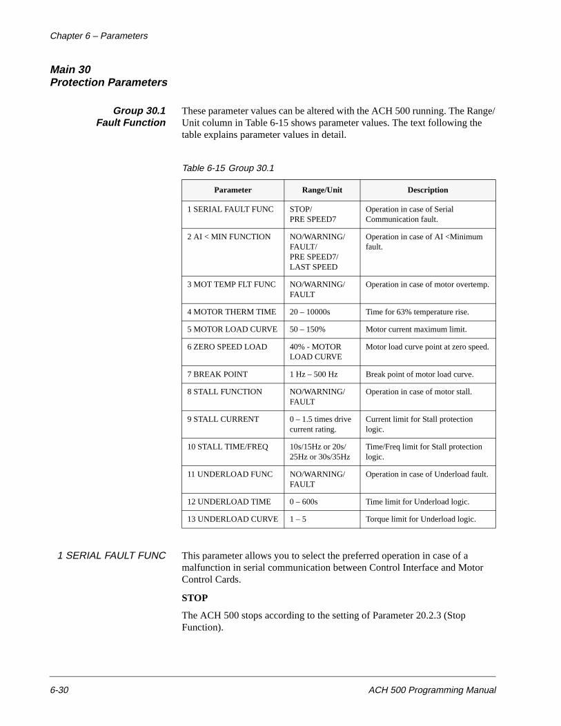
Chapter 6 – Parameters
6-30 ACH 500 Programming Manual
Main 30Protection Parameters
Group 30.1Fault Function
These parameter values can be altered with the ACH 500 running. The Range/Unit column in Table 6-15 shows parameter values. The text following the table explains parameter values in detail.
Table 6-15 Group 30.1
1 SERIAL FAULT FUNC This parameter allows you to select the preferred operation in case of a malfunction in serial communication between Control Interface and Motor Control Cards.
STOP
The ACH 500 stops according to the setting of Parameter 20.2.3 (Stop Function).
Parameter Range/Unit Description
1 SERIAL FAULT FUNC STOP/PRE SPEED7
Operation in case of Serial Communication fault.
2 AI < MIN FUNCTION NO/WARNING/ FAULT/PRE SPEED7/ LAST SPEED
Operation in case of AI <Minimum fault.
3 MOT TEMP FLT FUNC NO/WARNING/ FAULT
Operation in case of motor overtemp.
4 MOTOR THERM TIME 20 – 10000s Time for 63% temperature rise.
5 MOTOR LOAD CURVE 50 – 150% Motor current maximum limit.
6 ZERO SPEED LOAD 40% - MOTOR LOAD CURVE
Motor load curve point at zero speed.
7 BREAK POINT 1 Hz – 500 Hz Break point of motor load curve.
8 STALL FUNCTION NO/WARNING/ FAULT
Operation in case of motor stall.
9 STALL CURRENT 0 – 1.5 times drive current rating.
Current limit for Stall protection logic.
10 STALL TIME/FREQ 10s/15Hz or 20s/25Hz or 30s/35Hz
Time/Freq limit for Stall protection logic.
11 UNDERLOAD FUNC NO/WARNING/ FAULT
Operation in case of Underload fault.
12 UNDERLOAD TIME 0 – 600s Time limit for Underload logic.
13 UNDERLOAD CURVE 1 – 5 Torque limit for Underload logic.
Chapter 6 – Parameters
ACH 500 Programming Manual 6-31
PRE SPEED7
The ACH 500 drives the motor at a preset speed selected with Parameter 10.3.8 (Preset Speed 7) when in external mode.
Note: If the selected control location is Keypad, the ACH 500 stops in case of serial communication fault.
2 AI < MIN FUNCTION This parameter allows you to select the preferred operation in case Analog Input (1 or 2) (whichever is being used at that time) signal drops below the minimum setting, provided the minimum is set at 0.3 V/0.6 mA or above (“living zero”).
NO
No activity wanted.
WARNING
Warning indication on display.
FAULT
Fault indication on display and the drive stops according to the setting of Parameter 20.2.3 (Stop Function).
PRE SPEED7
Fault indication on display and the output frequency goes to the value set by Parameter 10.3.8 (Preset Speed 7).
LAST SPEED
Fault indication on display and the output frequency goes to the last speed (average over the last 10 seconds).
3 MOT TEMP FLT FUNC This parameter defines the operation of the motor thermal protection function.
NO
No activity wanted.
WARNING
Warning indication is displayed when the motor temperature reaches the warning level (95 percent of the nominal value).
FAULT
Displays a warning indication at warning level. Displays a fault indication and stops the ACH 500 when the motor temperature reaches 100 percent level.
The motor connected to the ACH 500 can be protected from overheating by motor thermal protection. The ACH 500 calculates the temperature rise of the motor using the following assumptions:
• The ambient temperature is 104°F (40°C).
• The motor is at ambient when power is applied to the ACH 500.
• When stopped, the motor cooling time is four times the cooling time when running.
Chapter 6 – Parameters
6-32 ACH 500 Programming Manual
Motor heating is calculated assuming a load curve. The load curve is defined by the Motor Load Curve, Zero Speed Load, and Break Point parameters. If Motor Load Curve is set to 100%, the Motor Thermal Protection allows the motor to be loaded to 100% of the current set by Start-up Data Parameter F (Motor Current -FLA). The load curve level should be adjusted if the ambient temperature differs from the nominal value.
The motor will heat above nominal temperature if it operates in the region above the curve, and cool if operated below the curve. The rate of heating and cooling is set by Motor Therm Time. Motor Therm Time is the time period within which the motor temperature reaches 63 percent of the final temperature rise. As a rule of thumb, Motor Thermal Time equals 35 times t6 (t6 in seconds is the safe operating time at locked rotor current given by the motor manufacturer).
Because of the simple thermal model used for calculating temperature rise, this technique of thermal protection may cause undesirable trips if the motor is run continuously at low frequencies. If your application requires continuous running at frequencies lower than 25 Hz, you may need to provide external cooling.
CAUTION: Motor thermal protection will not protect the motor if the cooling efficiency of the motor is reduced due to dust and dirt.
Figure 6-12 Motor Load Curve
50
100
150
[%]
30.1.6 Zero Speed Load
30.1.5 Motor Load Curve
30.1.7 Break PointMotor Fla
Frequency
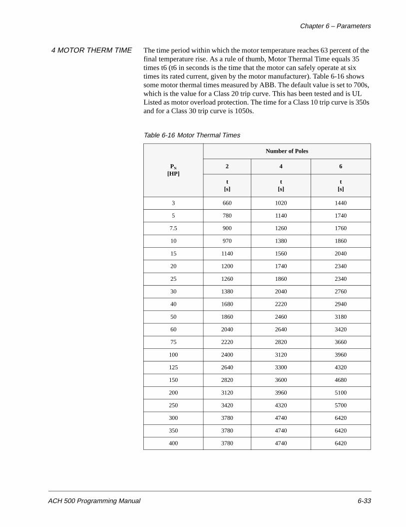
Chapter 6 – Parameters
ACH 500 Programming Manual 6-33
4 MOTOR THERM TIME The time period within which the motor temperature reaches 63 percent of the final temperature rise. As a rule of thumb, Motor Thermal Time equals 35 times t6 (t6 in seconds is the time that the motor can safely operate at six times its rated current, given by the motor manufacturer). Table 6-16 shows some motor thermal times measured by ABB. The default value is set to 700s, which is the value for a Class 20 trip curve. This has been tested and is UL Listed as motor overload protection. The time for a Class 10 trip curve is 350s and for a Class 30 trip curve is 1050s.
Table 6-16 Motor Thermal Times
PN
[HP]
Number of Poles
2 4 6
t[s]
t[s]
t[s]
3 660 1020 1440
5 780 1140 1740
7.5 900 1260 1760
10 970 1380 1860
15 1140 1560 2040
20 1200 1740 2340
25 1260 1860 2340
30 1380 2040 2760
40 1680 2220 2940
50 1860 2460 3180
60 2040 2640 3420
75 2220 2820 3660
100 2400 3120 3960
125 2640 3300 4320
150 2820 3600 4680
200 3120 3960 5100
250 3420 4320 5700
300 3780 4740 6420
350 3780 4740 6420
400 3780 4740 6420
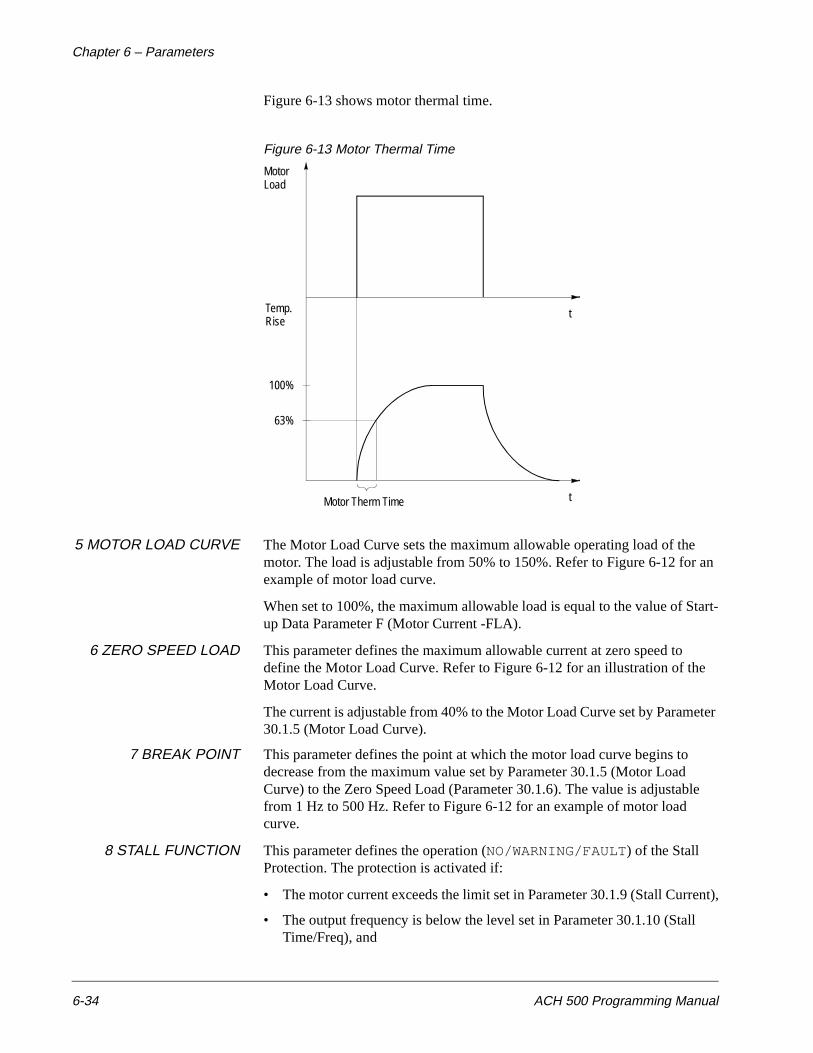
Chapter 6 – Parameters
6-34 ACH 500 Programming Manual
Figure 6-13 shows motor thermal time.
Figure 6-13 Motor Thermal Time
5 MOTOR LOAD CURVE The Motor Load Curve sets the maximum allowable operating load of the motor. The load is adjustable from 50% to 150%. Refer to Figure 6-12 for an example of motor load curve.
When set to 100%, the maximum allowable load is equal to the value of Start-up Data Parameter F (Motor Current -FLA).
6 ZERO SPEED LOAD This parameter defines the maximum allowable current at zero speed to define the Motor Load Curve. Refer to Figure 6-12 for an illustration of the Motor Load Curve.
The current is adjustable from 40% to the Motor Load Curve set by Parameter 30.1.5 (Motor Load Curve).
7 BREAK POINT This parameter defines the point at which the motor load curve begins to decrease from the maximum value set by Parameter 30.1.5 (Motor Load Curve) to the Zero Speed Load (Parameter 30.1.6). The value is adjustable from 1 Hz to 500 Hz. Refer to Figure 6-12 for an example of motor load curve.
8 STALL FUNCTION This parameter defines the operation (NO/WARNING/FAULT) of the Stall Protection. The protection is activated if:
• The motor current exceeds the limit set in Parameter 30.1.9 (Stall Current),
• The output frequency is below the level set in Parameter 30.1.10 (Stall Time/Freq), and
MotorLoad
100%
Temp.Rise
63%
Motor Therm Time
t
t
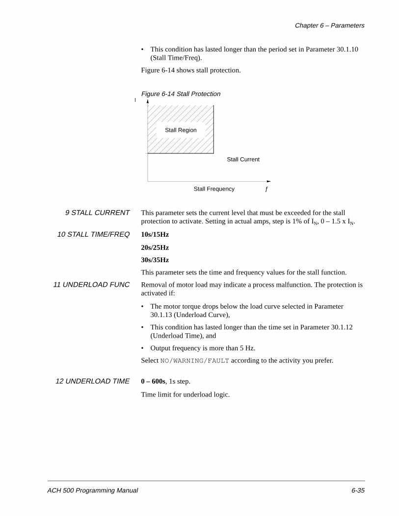
Chapter 6 – Parameters
ACH 500 Programming Manual 6-35
• This condition has lasted longer than the period set in Parameter 30.1.10 (Stall Time/Freq).
Figure 6-14 shows stall protection.
Figure 6-14 Stall Protection
9 STALL CURRENT This parameter sets the current level that must be exceeded for the stall protection to activate. Setting in actual amps, step is 1% of IN, 0 – 1.5 x IN.
10 STALL TIME/FREQ 10s/15Hz
20s/25Hz
30s/35Hz
This parameter sets the time and frequency values for the stall function.
11 UNDERLOAD FUNC Removal of motor load may indicate a process malfunction. The protection is activated if:
• The motor torque drops below the load curve selected in Parameter 30.1.13 (Underload Curve),
• This condition has lasted longer than the time set in Parameter 30.1.12 (Underload Time), and
• Output frequency is more than 5 Hz.
Select NO/WARNING/FAULT according to the activity you prefer.
12 UNDERLOAD TIME 0 – 600s, 1s step.
Time limit for underload logic.
Stall Region
Stall Current
ƒStall Frequency

Chapter 6 – Parameters
6-36 ACH 500 Programming Manual
Figure 6-15 shows underload protection.
Figure 6-15 Underload Protection
13 UNDERLOAD CURVE This parameter provides you with five selectable curves.
Torque limit for underload logic.
Figure 6-16 shows five available Underload Curve types. If the load drops below the set curve for a longer time than the time set by Parameter 30.1.12, the underload protection will activate. Curves 1 – 3 reach maximum at the Field Weakening Point set by Parameter 20.4.4 (Field Weak Point).
Figure 6-16 Underload Curve Types
Underload Curve
T M
5Hz ƒ
Underload Region
ƒ
% of
100
80
60
40
20
0
120 Hzƒ [Hz]
3
2
1 5
4
MotorTorque
70%
50%
30%
FWP
Chapter 6 – Parameters
ACH 500 Programming Manual 6-37
Group 30.2Automatic Reset
These parameter values can be altered with the ACH 500 running. The Range/Unit column in Table 6-17 shows parameter values. The text following the table explains parameter values in detail.
Table 6-17 Group 30.2
1 NUMBER OF RESETS Sets the number of resets the ACH 500 will attempt before staying shut down and indicating a fault.
2 TIME WINDOW The maximum number of faults per time period to keep the Automatic Fault Reset System active is given with Parameters 30.2.1 (Number of Resets) and 30.2.2 (Time Window).
If more faults occur or a fault persists longer than Trial Time, the drive stops.
The Automatic Fault Reset System resets the faults selected with Parameters 30.2.4 (Overvoltage), 30.2.5 (Undervoltage), 30.2.6 (Overcurrent), and 30.2.7 (AI Signal < Min).
3 TIME BETW.RESET ATTEMPTS
0 – 120s
This parameter sets the time that the ACH 500 will wait after a fault occurs before attempting to reset. If set to zero, the ACH 500 will reset immediately making the fault transparent to the user. If set to a value greater than zero, the drive will wait before resetting and will count down the time until reset on the digital display. For AI Signal < Min Fault, the ACH 500 will start immediately when the signal returns.
4 OVERVOLTAGE If you select YES, the ACH 500 resumes operation when the DC bus voltage returns to normal level.
Parameter Range/Unit Description
1 NUMBER OF RESETS 0 – 5 Number of faults limit for Autoreset logic.
2 TIME WINDOW 1s – 180s Time limit for Autoreset logic.
3 TIME BETW. RESET ATTEMPTS
0s– 120s Time delay between reset attempts.
4 OVERVOLTAGE NO/YES Enable automatic fault reset.
5 UNDERVOLTAGE NO/YES Enable automatic fault reset when bus voltage returns to normal.
6 OVERCURRENT NO/YES Enable automatic fault reset.
7 AI SIGNAL < MIN NO/YES Enable automatic fault reset when AI is greater than 0.25V.

Chapter 6 – Parameters
6-38 ACH 500 Programming Manual
5 UNDERVOLTAGE If you select YES, the ACH 500 resumes operation when the DC bus voltage returns to normal level. If the number of reset attempts is set to 0 and this parameter is set to YES, the drive will always reset in an undervoltage condition. If the number of reset attempts is greater than 0, the drive counts the number of undervoltage faults.
6 OVERCURRENT If you select YES, the fault resets automatically and the ACH 500 resumes normal operation.
7 AI SIGNAL < MIN If you select YES, the drive resets when the analog input signal returns to a level above the minimum.
Group 30.3Supervision
These parameter values can be altered with the ACH 500 running. The Range/Unit column in Table 6-18 shows parameter values. The text following the table explains parameter values in detail.
Table 6-18 Group 30.3
Parameter Range/Unit Description
1 OUTPUT FREQ 1 FUNC NO/LOW LIMIT/ HIGH LIMIT
Output Frequency 1 supervision.
2 OUTPUT FREQ 1 LIM 0 – 500 Hz (ACH 501) 0 – 120 Hz (ACH 502)
Output Frequency 1 supervision limit.
3 OUTPUT FREQ 2 FUNC NO/LOW LIMIT/ HIGH LIMIT
Output Frequency 2 supervision.
4 OUTPUT FREQ 2 LIM 0 – 500 Hz (ACH 501) 0 – 120 Hz (ACH 502)
Output Frequency 2 supervision limit.
5 CURRENT FUNCTION NO/LOW LIMIT/ HIGH LIMIT
Motor Current supervision.
6 CURRENT LIMIT 0 – 2 times drive output current
Motor Current supervision limit.
7 REF1 FUNCTION NO/LOW LIMIT/ HIGH LIMIT
Reference 1 supervision.
8 REF1 LIMIT 0 – 500 Hz (ACH 501) 0 – 120 Hz (ACH 502)
Reference 1 supervision limit.
9 REF2 FUNCTION NO/LOW LIMIT/ HIGH LIMIT
Reference 2 supervision.
10 REF2 LIMIT 0 – 100% Reference 2 supervision limit.
11 SUPERVIS MESSAGES
ON/OFF Turn off display of supervision messages.
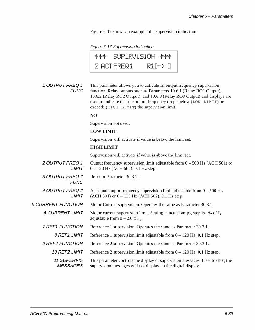
Chapter 6 – Parameters
ACH 500 Programming Manual 6-39
Figure 6-17 shows an example of a supervision indication.
Figure 6-17 Supervision Indication
1 OUTPUT FREQ 1FUNC
This parameter allows you to activate an output frequency supervision function. Relay outputs such as Parameters 10.6.1 (Relay RO1 Output), 10.6.2 (Relay RO2 Output), and 10.6.3 (Relay RO3 Output) and displays are used to indicate that the output frequency drops below (LOW LIMIT) or exceeds (HIGH LIMIT) the supervision limit.
NO
Supervision not used.
LOW LIMIT
Supervision will activate if value is below the limit set.
HIGH LIMIT
Supervision will activate if value is above the limit set.
2 OUTPUT FREQ 1LIMIT
Output frequency supervision limit adjustable from 0 – 500 Hz (ACH 501) or0 – 120 Hz (ACH 502), 0.1 Hz step.
3 OUTPUT FREQ 2FUNC
Refer to Parameter 30.3.1.
4 OUTPUT FREQ 2LIMIT
A second output frequency supervision limit adjustable from 0 – 500 Hz (ACH 501) or 0 – 120 Hz (ACH 502), 0.1 Hz step.
5 CURRENT FUNCTION Motor Current supervision. Operates the same as Parameter 30.3.1.
6 CURRENT LIMIT Motor current supervision limit. Setting in actual amps, step is 1% of IR, adjustable from 0 – 2.0 x IR.
7 REF1 FUNCTION Reference 1 supervision. Operates the same as Parameter 30.3.1.
8 REF1 LIMIT Reference 1 supervision limit adjustable from 0 – 120 Hz, 0.1 Hz step.
9 REF2 FUNCTION Reference 2 supervision. Operates the same as Parameter 30.3.1.
10 REF2 LIMIT Reference 2 supervision limit adjustable from 0 – 120 Hz, 0.1 Hz step.
11 SUPERVISMESSAGES
This parameter controls the display of supervision messages. If set to OFF, the supervision messages will not display on the digital display.
Chapter 6 – Parameters
6-40 ACH 500 Programming Manual
Group 30.4Information
You cannot alter these parameter values. The Range/Unit column in Table 6-19 shows parameter values. The text following the table explains parameter values in detail.
Table 6-19 Group 30.4
1 CRI PROG VERSION This parameter displays the Control Interface Card version installed in your ACH 500.
2 MC PROG VERSION This parameter displays the Motor Control Card version installed in your ACH 500.
3 TEST DATE This parameter displays the date of the ACH 500 final test.
Group 30.5I/O Status
You cannot alter these parameter values. The Range/Unit column in Table 6-20 shows parameter values. The text following the table explains parameter values in detail. The parameters in this group show the status of the I/O.
Table 6-20 Group 30.5
Parameter Range/Unit Description
1 CRI PROG VERSION CRHxxy Control Interface Card program version.
2 MC PROG VERSION MCRxxy/CNTxxy Motor Control Card program version.
3 TEST DATE YY.MM.DD Test date (year,month,day).
Parameter Range/Unit Description
1 DI1-6 STATUS 000000 Indication of the status of the six digital inputs. 0=Open; 1=Closed
2 AI1 V/mA 0.00/ 0.00 Signal at Analog Input 1 in volts and milliamps
3 AI2 V/mA 0.00/ 0.00 Signal at Analog Input 2 in volts and milliamps
4 RO1-3 STATUS 000 Indication of the status of the three relay outputs. 0=Open; 1=Closed
5 AO1 mA/% 0.00/ 0% Signal at Analog Output 1 in milliamps and percent.
6 AO2 mA/% 0.00/ 0% Signal at Analog Output 2 in milliamps and percent.
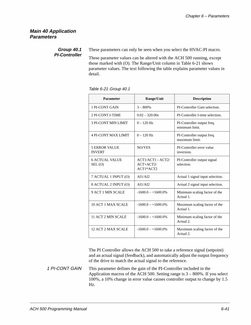
Chapter 6 – Parameters
ACH 500 Programming Manual 6-41
Main 40 Application Parameters
Group 40.1PI-Controller
These parameters can only be seen when you select the HVAC-PI macro.
These parameter values can be altered with the ACH 500 running, except those marked with (O). The Range/Unit column in Table 6-21 shows parameter values. The text following the table explains parameter values in detail.
Table 6-21 Group 40.1
The PI Controller allows the ACH 500 to take a reference signal (setpoint) and an actual signal (feedback), and automatically adjust the output frequency of the drive to match the actual signal to the reference.
1 PI-CONT GAIN This parameter defines the gain of the PI-Controller included in the Application macros of the ACH 500. Setting range is 3 – 800%. If you select 100%, a 10% change in error value causes controller output to change by 1.5 Hz.
Parameter Range/Unit Description
1 PI-CONT GAIN 3 – 800% PI-Controller Gain selection.
2 PI-CONT I-TIME 0.02 – 320.00s PI-Controller I-time selection.
3 PI-CONT MIN LIMIT 0 – 120 Hz PI-Controller output freq. minimum limit.
4 PI-CONT MAX LIMIT 0 – 120 Hz PI-Controller output freq. maximum limit.
5 ERROR VALUE INVERT
NO/YES PI-Controller error value inversion.
6 ACTUAL VALUE SEL (O)
ACT1/ACT1 - ACT2/ ACT+ACT2/ACT1*ACT2
PI-Controller output signal selection.
7 ACTUAL 1 INPUT (O) AI1/AI2 Actual 1 signal input selection.
8 ACTUAL 2 INPUT (O) AI1/AI2 Actual 2 signal input selection.
9 ACT 1 MIN SCALE -1600.0 – +1600.0% Minimum scaling factor of the Actual 1.
10 ACT 1 MAX SCALE -1600.0 – +1600.0% Maximum scaling factor of the Actual 1.
11 ACT 2 MIN SCALE -1600.0 – +1600.0% Minimum scaling factor of the Actual 2.
12 ACT 2 MAX SCALE -1600.0 – +1600.0% Maximum scaling factor of the Actual 2.
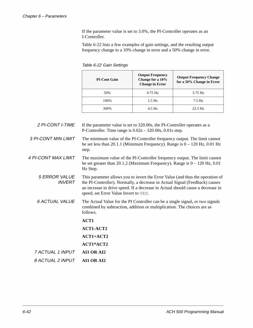
Chapter 6 – Parameters
6-42 ACH 500 Programming Manual
If the parameter value is set to 3.0%, the PI-Controller operates as an I-Controller.
Table 6-22 lists a few examples of gain settings, and the resulting output frequency change to a 10% change in error and a 50% change in error.
Table 6-22 Gain Settings
2 PI-CONT I-TIME If the parameter value is set to 320.00s, the PI-Controller operates as a P-Controller. Time range is 0.02s – 320.00s, 0.01s step.
3 PI-CONT MIN LIMIT The minimum value of the PI-Controller frequency output. The limit cannot be set less than 20.1.1 (Minimum Frequency). Range is 0 – 120 Hz, 0.01 Hz step.
4 PI-CONT MAX LIMIT The maximum value of the PI-Controller frequency output. The limit cannot be set greater than 20.1.2 (Maximum Frequency). Range is 0 – 120 Hz, 0.01 Hz Step.
5 ERROR VALUEINVERT
This parameter allows you to invert the Error Value (and thus the operation of the PI-Controller). Normally, a decrease in Actual Signal (Feedback) causes an increase in drive speed. If a decrease in Actual should cause a decrease in speed, set Error Value Invert to YES.
6 ACTUAL VALUE The Actual Value for the PI Controller can be a single signal, or two signals combined by subtraction, addition or multiplication. The choices are as follows.
ACT1
ACT1-ACT2
ACT1+ACT2
ACT1*ACT2
7 ACTUAL 1 INPUT AI1 OR AI2
8 ACTUAL 2 INPUT AI1 OR AI2
PI-Cont GainOutput Frequency Change for a 10% Change in Error
Output Frequency Change for a 50% Change in Error
50% 0.75 Hz 3.75 Hz
100% 1.5 Hz 7.5 Hz
300% 4.5 Hz 22.5 Hz
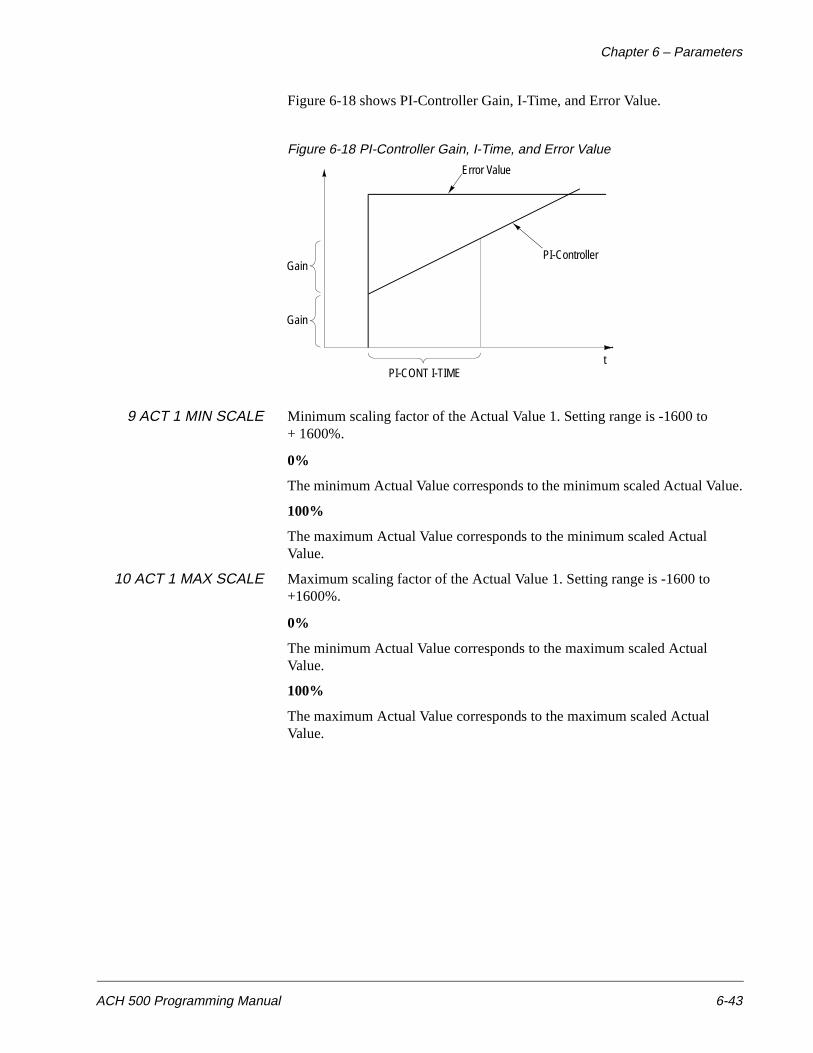
Chapter 6 – Parameters
ACH 500 Programming Manual 6-43
Figure 6-18 shows PI-Controller Gain, I-Time, and Error Value.
Figure 6-18 PI-Controller Gain, I-Time, and Error Value
9 ACT 1 MIN SCALE Minimum scaling factor of the Actual Value 1. Setting range is -1600 to + 1600%.
0%
The minimum Actual Value corresponds to the minimum scaled Actual Value.
100%
The maximum Actual Value corresponds to the minimum scaled Actual Value.
10 ACT 1 MAX SCALE Maximum scaling factor of the Actual Value 1. Setting range is -1600 to +1600%.
0%
The minimum Actual Value corresponds to the maximum scaled Actual Value.
100%
The maximum Actual Value corresponds to the maximum scaled Actual Value.
Error Value
PI-ControllerGain
Gain
PI-CONT I-TIMEt
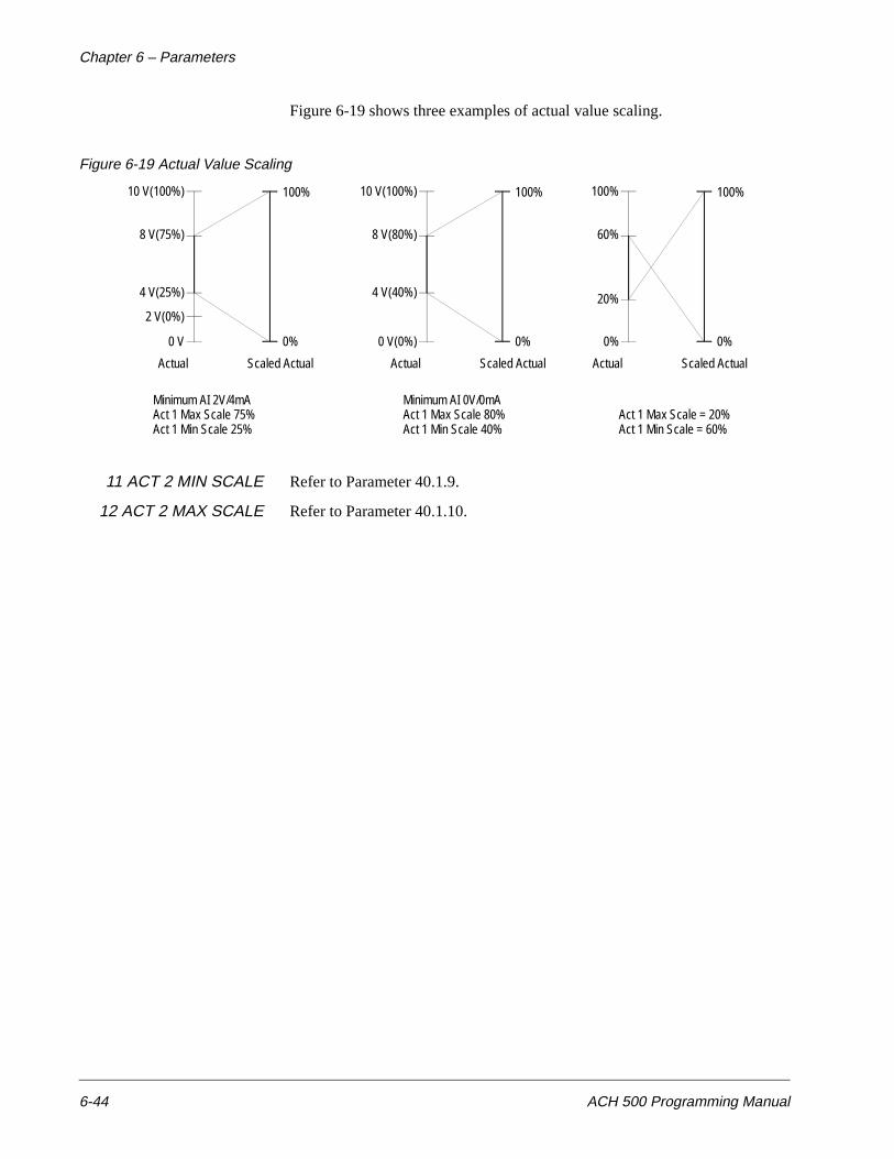
Chapter 6 – Parameters
6-44 ACH 500 Programming Manual
Figure 6-19 shows three examples of actual value scaling.
Figure 6-19 Actual Value Scaling
11 ACT 2 MIN SCALE Refer to Parameter 40.1.9.
12 ACT 2 MAX SCALE Refer to Parameter 40.1.10.
10 V(100%)
8 V(75%)
4 V(25%)
2 V(0%)
0 V 0%
100%
Actual Scaled Actual
10 V(100%)
8 V(80%)
4 V(40%)
0 V(0%) 0%
100%
Actual Scaled Actual
100%
60%
20%
0% 0%
100%
Actual Scaled Actual
Minimum AI 2V/4mAAct 1 Max Scale 75%Act 1 Min Scale 25%
Minimum AI 0V/0mAAct 1 Max Scale 80%Act 1 Min Scale 40%
Act 1 Max Scale = 20%Act 1 Min Scale = 60%
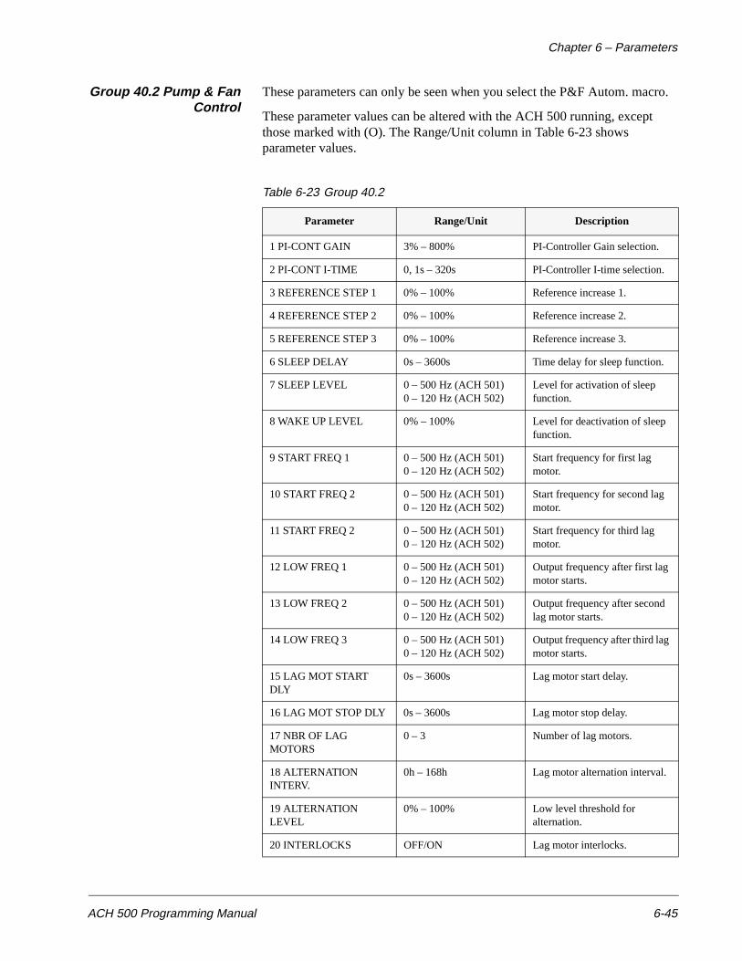
Chapter 6 – Parameters
ACH 500 Programming Manual 6-45
Group 40.2 Pump & FanControl
These parameters can only be seen when you select the P&F Autom. macro.
These parameter values can be altered with the ACH 500 running, except those marked with (O). The Range/Unit column in Table 6-23 shows parameter values.
Table 6-23 Group 40.2
Parameter Range/Unit Description
1 PI-CONT GAIN 3% – 800% PI-Controller Gain selection.
2 PI-CONT I-TIME 0, 1s – 320s PI-Controller I-time selection.
3 REFERENCE STEP 1 0% – 100% Reference increase 1.
4 REFERENCE STEP 2 0% – 100% Reference increase 2.
5 REFERENCE STEP 3 0% – 100% Reference increase 3.
6 SLEEP DELAY 0s – 3600s Time delay for sleep function.
7 SLEEP LEVEL 0 – 500 Hz (ACH 501) 0 – 120 Hz (ACH 502)
Level for activation of sleep function.
8 WAKE UP LEVEL 0% – 100% Level for deactivation of sleep function.
9 START FREQ 1 0 – 500 Hz (ACH 501) 0 – 120 Hz (ACH 502)
Start frequency for first lag motor.
10 START FREQ 2 0 – 500 Hz (ACH 501) 0 – 120 Hz (ACH 502)
Start frequency for second lag motor.
11 START FREQ 2 0 – 500 Hz (ACH 501) 0 – 120 Hz (ACH 502)
Start frequency for third lag motor.
12 LOW FREQ 1 0 – 500 Hz (ACH 501) 0 – 120 Hz (ACH 502)
Output frequency after first lag motor starts.
13 LOW FREQ 2 0 – 500 Hz (ACH 501) 0 – 120 Hz (ACH 502)
Output frequency after second lag motor starts.
14 LOW FREQ 3 0 – 500 Hz (ACH 501) 0 – 120 Hz (ACH 502)
Output frequency after third lag motor starts.
15 LAG MOT START DLY
0s – 3600s Lag motor start delay.
16 LAG MOT STOP DLY 0s – 3600s Lag motor stop delay.
17 NBR OF LAG MOTORS
0 – 3 Number of lag motors.
18 ALTERNATION INTERV.
0h – 168h Lag motor alternation interval.
19 ALTERNATION LEVEL
0% – 100% Low level threshold for alternation.
20 INTERLOCKS OFF/ON Lag motor interlocks.
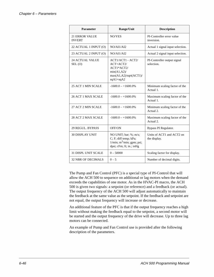
Chapter 6 – Parameters
6-46 ACH 500 Programming Manual
The Pump and Fan Control (PFC) is a special type of PI-Control that will allow the ACH 500 to sequence on additional or lag motors when the demand exceeds the capabilities of one motor. As in the HVAC-PI macro, the ACH 500 is given two signals: a setpoint (or reference) and a feedback (or actual). The output frequency of the ACH 500 will adjust automatically to maintain the feedback at the same value as the setpoint. If the feedback and setpoint are not equal, the output frequency will increase or decrease.
An additional feature of the PFC is that if the output frequency reaches a high limit without making the feedback equal to the setpoint, a second motor will be started and the output frequency of the drive will decrease. Up to three lag motors can be connected.
An example of Pump and Fan Control use is provided after the following description of the parameters.
21 ERROR VALUE INVERT
NO/YES PI-Controller error value inversion.
22 ACTUAL 1 INPUT (O) NO/AI1/AI2 Actual 1 signal input selection.
23 ACTUAL 2 INPUT (O) NO/AI1/AI2 Actual 2 signal input selection.
24 ACTUAL VALUE SEL (O)
ACT1/ACT1 - ACT2/ ACT+ACT2/ACT1*ACT2/min(A1,A2)/max(A1,A2)/sqrt(ACT1)/sqA1+sqA2
PI-Controller output signal selection.
25 ACT 1 MIN SCALE -1600.0 – +1600.0% Minimum scaling factor of the Actual 1.
26 ACT 1 MAX SCALE -1600.0 – +1600.0% Maximum scaling factor of the Actual 1.
27 ACT 2 MIN SCALE -1600.0 – +1600.0% Minimum scaling factor of the Actual 2.
28 ACT 2 MAX SCALE -1600.0 – +1600.0% Maximum scaling factor of the Actual 2.
29 REGUL. BYPASS OFF/ON Bypass PI Regulator.
30 DISPLAY UNIT NO UNIT; bar; %; m/s; C; F; diff temp; kPa; 1/min; m3/min; gpm; psi; dpsi; cFm; ft; in.; inHg
Units of ACT1 and ACT2 on the display.
31 DISPL UNIT SCALE 0 – 50000 Scaling factor for display.
32 NBR OF DECIMALS 0 – 5 Number of decimal digits.
Parameter Range/Unit Description
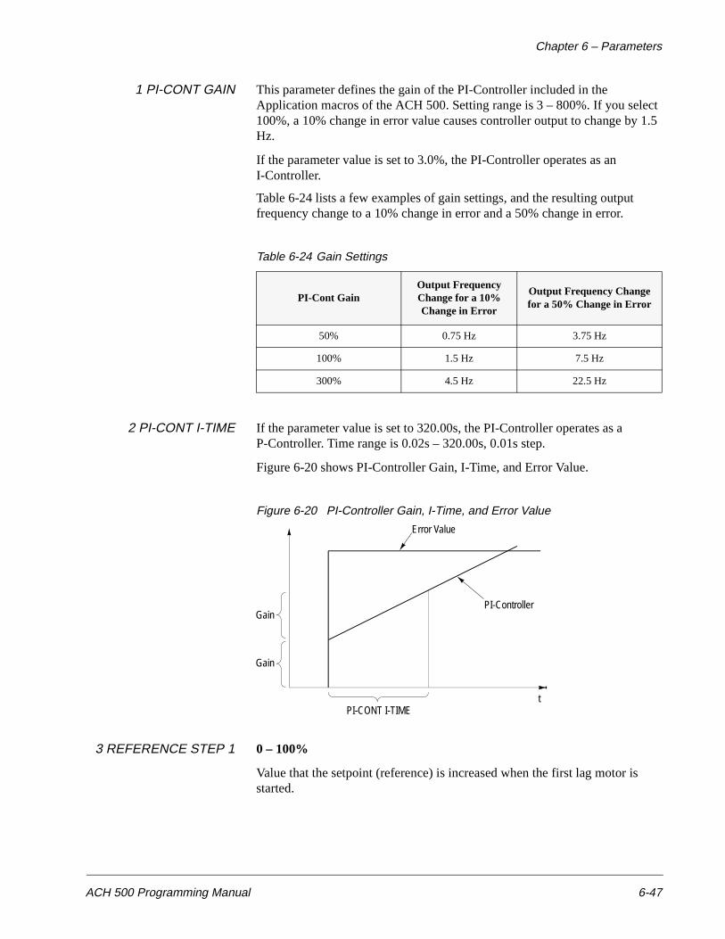
Chapter 6 – Parameters
ACH 500 Programming Manual 6-47
1 PI-CONT GAIN This parameter defines the gain of the PI-Controller included in the Application macros of the ACH 500. Setting range is 3 – 800%. If you select 100%, a 10% change in error value causes controller output to change by 1.5 Hz.
If the parameter value is set to 3.0%, the PI-Controller operates as an I-Controller.
Table 6-24 lists a few examples of gain settings, and the resulting output frequency change to a 10% change in error and a 50% change in error.
Table 6-24 Gain Settings
2 PI-CONT I-TIME If the parameter value is set to 320.00s, the PI-Controller operates as a P-Controller. Time range is 0.02s – 320.00s, 0.01s step.
Figure 6-20 shows PI-Controller Gain, I-Time, and Error Value.
Figure 6-20 PI-Controller Gain, I-Time, and Error Value
3 REFERENCE STEP 1 0 – 100%
Value that the setpoint (reference) is increased when the first lag motor is started.
PI-Cont GainOutput Frequency Change for a 10% Change in Error
Output Frequency Change for a 50% Change in Error
50% 0.75 Hz 3.75 Hz
100% 1.5 Hz 7.5 Hz
300% 4.5 Hz 22.5 Hz
Error Value
PI-ControllerGain
Gain
PI-CONT I-TIMEt
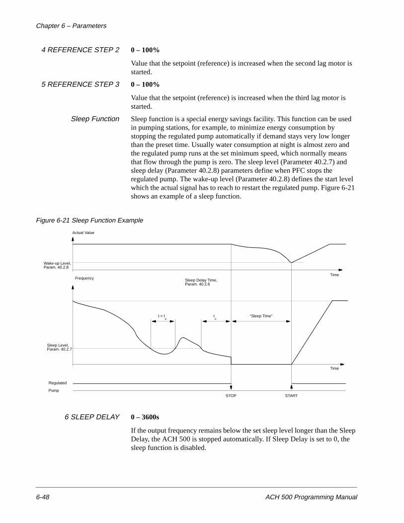
Chapter 6 – Parameters
6-48 ACH 500 Programming Manual
4 REFERENCE STEP 2 0 – 100%
Value that the setpoint (reference) is increased when the second lag motor is started.
5 REFERENCE STEP 3 0 – 100%
Value that the setpoint (reference) is increased when the third lag motor is started.
Sleep Function Sleep function is a special energy savings facility. This function can be used in pumping stations, for example, to minimize energy consumption by stopping the regulated pump automatically if demand stays very low longer than the preset time. Usually water consumption at night is almost zero and the regulated pump runs at the set minimum speed, which normally means that flow through the pump is zero. The sleep level (Parameter 40.2.7) and sleep delay (Parameter 40.2.8) parameters define when PFC stops the regulated pump. The wake-up level (Parameter 40.2.8) defines the start level which the actual signal has to reach to restart the regulated pump. Figure 6-21 shows an example of a sleep function.
Figure 6-21 Sleep Function Example
6 SLEEP DELAY 0 – 3600s
If the output frequency remains below the set sleep level longer than the Sleep Delay, the ACH 500 is stopped automatically. If Sleep Delay is set to 0, the sleep function is disabled.
Actual Value
Wake-up Level,Param. 40.2.8
Sleep Level,Param. 40.2.7
Regulated
Pump
Frequency Sleep Delay Time,Param. 40.2.6
t < td
td
“Sleep Time”
Time
Time
STOP START
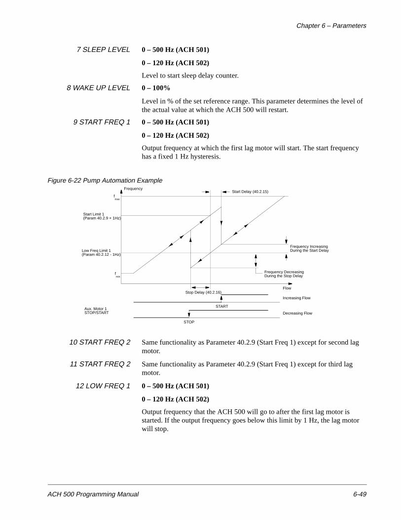
Chapter 6 – Parameters
ACH 500 Programming Manual 6-49
7 SLEEP LEVEL 0 – 500 Hz (ACH 501)
0 – 120 Hz (ACH 502)
Level to start sleep delay counter.
8 WAKE UP LEVEL 0 – 100%
Level in % of the set reference range. This parameter determines the level of the actual value at which the ACH 500 will restart.
9 START FREQ 1 0 – 500 Hz (ACH 501)
0 – 120 Hz (ACH 502)
Output frequency at which the first lag motor will start. The start frequency has a fixed 1 Hz hysteresis.
Figure 6-22 Pump Automation Example
10 START FREQ 2 Same functionality as Parameter 40.2.9 (Start Freq 1) except for second lag motor.
11 START FREQ 2 Same functionality as Parameter 40.2.9 (Start Freq 1) except for third lag motor.
12 LOW FREQ 1 0 – 500 Hz (ACH 501)
0 – 120 Hz (ACH 502)
Output frequency that the ACH 500 will go to after the first lag motor is started. If the output frequency goes below this limit by 1 Hz, the lag motor will stop.
Frequency
fmax
fmin
Start Limit 1(Param 40.2.9 + 1Hz)
Low Freq Limit 1(Param 40.2.12 - 1Hz)
Aux. Motor 1STOP/START
START
STOP
Flow
Increasing Flow
Decreasing Flow
Stop Delay (40.2.16)
Start Delay (40.2.15)
Frequency IncreasingDuring the Start Delay
Frequency DecreasingDuring the Stop Delay
Chapter 6 – Parameters
6-50 ACH 500 Programming Manual
13 LOW FREQ 2 0 – 500 Hz (ACH 501)
0 – 120 Hz (ACH 502)
Output frequency that the ACH 500 will go to after the second lag motor is started. If the output frequency goes below this limit by 1 Hz, the lag motor will stop.
14 LOW FREQ 3 0 – 500 Hz (ACH 501)
0 – 120 Hz (ACH 502)
Output frequency that the ACH 500 will go to after the third lag motor is started. If the output frequency goes below this limit by 1 Hz, the lag motor will stop.
15 LAG MOT START DLY 0 – 3600s
Start delay for lag motors to prevent the lag motor from starting due to a momentary crossing of the start limit. The frequency must remain above the start limit for the period of time set by this parameter before the lag motor will start.
16 LAG MOT STOP DLY 0 – 3600s
Stop delay for lag motors to prevent the lag motor from stopping due to a momentary crossing of the stop limit. The frequency must remain below the stop limit for the period of time set by this parameter before the lag motor will stop.
17 NBR OF LAGMOTORS
0 – 3
Number of lag motors in the system. Requires I/O Extension Board to use third motor.
18 ALTERNATIONINTERV.
0 min – 168 hrs
Time interval for changing the sequencing order of the motors. Alternation only occurs when the actual signal goes below the level set by Parameter 40.2.19 (Alternation Level). Setting the value to 00h 00min disables the alternation function. This must be done with the drive stopped. The interval time only counts the time that the ACS 500 is commanded to run.
19 ALTERNATIONLEVEL
0 – 100%
Actual value level below which the alternation takes place. When the time set by Parameter 40.2.18 (Alternation Interv.) is exceeded and the level goes below the level set by this parameter, the order of the lag motors will change.
With this parameter set to 0, automatic alternation only takes place when the ACH 500 is stopped (normal or “sleep”).
The alternation level is in relation to the set maximum frequency and to the capacity of the system such that, if a value of the parameter is 45% and the system has only two motors, the automatic exchange takes place at the frequency of 0.45/50 x fmax.
If there are more motors connected, the percentage value corresponding to the set maximum frequency is:
Chapter 6 – Parameters
ACH 500 Programming Manual 6-51
1+1 motors 50.0%
1+2 motors 33.3%
1+3 motors 25.0%
For example: if the values of the parameters are:
Nbr of lag motors (40.2.17) = 2
Alternation level (40.2.19) = 25%
Max frequency (20.1.2) = 51 Hz
the alternation takes place at 38.3 Hz (25%/33.3% x 51 Hz) if the following conditions are true:
• Alternation interval time has elapsed,
• Actual value is below the set alternation level,
• Minimum one lag motor is not running, and
• The ACH 500 is not running at a preset speed (DI/param., Group 10.3).
When all the conditions are valid, PFC stops all motors, changes the order of the motors, and starts the motors using the new start order. The starting order cannot be changed externally.
The start order and the elapsed run time remain in the ACH 500 memory during a power interruption.
Note: If only the regulated pump is used, cancel the alternation operation by setting Parameter 40.2.18 (Alternation Interv.) to 00 h 00 min. This releases relay outputs RO1 to RO4 for other use.
20 INTERLOCKS ON/OFF
Digital inputs can be used as interlocks for the connected motors. A contact from the disconnect at each motor is brought to a digital input. If a motor is taken out of service, the ACH 500 will skip that motor when it is needed and select the next available pump. If this parameter is set to ON, DI2 DI3, and DI4 are reserved for the interlocks. The I/O extension board must be ordered to use this function. If this function is set to OFF, the digital inputs are available for other functions.
If an interlocking function is in use and one of the interlocking signals disappears while the motors are running, the ACH 500 will stop and a corresponding output relay (RO1 to RO4) will release and stop the respective motor. If other motors are available, PFC connects one of those instead and starts the ACH 500 again.
21 ERROR VALUE INV. NO/YES
This parameter allows you to invert the Error Value (and thus the operation of the PI-Controller). Normally, a decrease in Actual Signal (Feedback) causes an increase in drive speed. If a decrease in Actual should cause a decrease in speed, set Error Value Invert to YES.
22 ACTUAL 1 INPUT AI1 OR AI2
Chapter 6 – Parameters
6-52 ACH 500 Programming Manual
23 ACTUAL 2 INPUT AI1 OR AI2
24 ACTUAL VALUE SEL The Actual Value for the PI Controller can be a single signal, or two signals combined by subtraction, addition or multiplication. The choices are as follows.
ACT1
ACT1-ACT2
ACT1+ACT2
ACT1*ACT2
min(A1,A2)
Actual value is ACT1 or ACT2, whichever is lower.
max(A1,A2)
Actual value is ACT1 or ACT2, whichever is higher.
sqrt(ACT1)
Square root of ACT1.
sqA1+sqA2
Square root of ACT1 + square root of ACT2.
25 ACT 1 MIN SCALE Minimum scaling factor of the Actual Value 1. Setting range is -1600 to + 1600%.
0%
The minimum Actual Value corresponds to the minimum scaled Actual Value.
100%
The maximum Actual Value corresponds to the minimum scaled Actual Value.
26 ACT 1 MAX SCALE Maximum scaling factor of the Actual Value 1. Setting range is -1600 to +1600%.
0%
The minimum Actual Value corresponds to the maximum scaled Actual Value.
100%
The maximum Actual Value corresponds to the maximum scaled Actual Value.
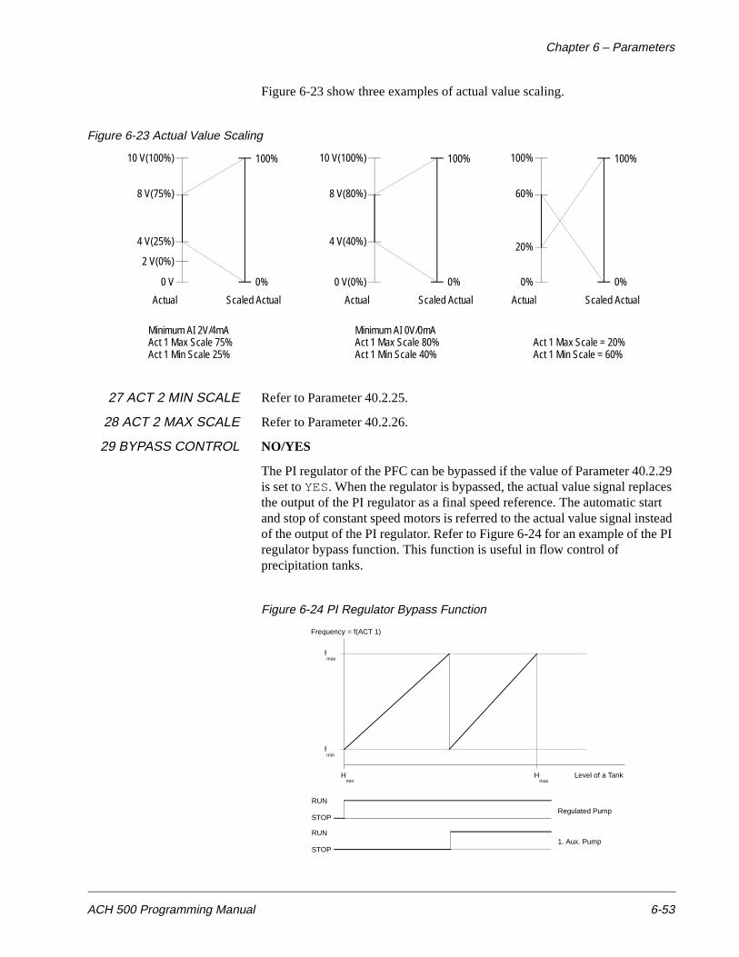
Chapter 6 – Parameters
ACH 500 Programming Manual 6-53
Figure 6-23 show three examples of actual value scaling.
Figure 6-23 Actual Value Scaling
27 ACT 2 MIN SCALE Refer to Parameter 40.2.25.
28 ACT 2 MAX SCALE Refer to Parameter 40.2.26.
29 BYPASS CONTROL NO/YES
The PI regulator of the PFC can be bypassed if the value of Parameter 40.2.29 is set to YES. When the regulator is bypassed, the actual value signal replaces the output of the PI regulator as a final speed reference. The automatic start and stop of constant speed motors is referred to the actual value signal instead of the output of the PI regulator. Refer to Figure 6-24 for an example of the PI regulator bypass function. This function is useful in flow control of precipitation tanks.
Figure 6-24 PI Regulator Bypass Function
10 V(100%)
8 V(75%)
4 V(25%)
2 V(0%)
0 V 0%
100%
Actual Scaled Actual
10 V(100%)
8 V(80%)
4 V(40%)
0 V(0%) 0%
100%
Actual Scaled Actual
100%
60%
20%
0% 0%
100%
Actual Scaled Actual
Minimum AI 2V/4mAAct 1 Max Scale 75%Act 1 Min Scale 25%
Minimum AI 0V/0mAAct 1 Max Scale 80%Act 1 Min Scale 40%
Act 1 Max Scale = 20%Act 1 Min Scale = 60%
Frequency = f(ACT 1)
fmax
fmin
Hmin
Hmax
Level of a Tank
RUN
STOP
RUN
STOP
Regulated Pump
1. Aux. Pump
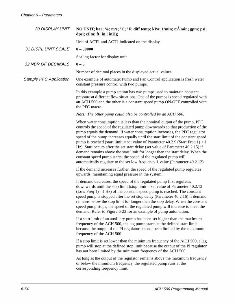
Chapter 6 – Parameters
6-54 ACH 500 Programming Manual
30 DISPLAY UNIT NO UNIT; bar; %; m/s; °C; °F; diff temp; kPa; 1/min; m 3/min; gpm; psi; dpsi; cFm; ft; in.; inHg
Unit of ACT1 and ACT2 indicated on the display.
31 DISPL UNIT SCALE 0 – 50000
Scaling factor for display unit.
32 NBR OF DECIMALS 0 – 5
Number of decimal places in the displayed actual values.
Sample PFC Application One example of automatic Pump and Fan Control application is fresh water constant pressure control with two pumps.
In this example a pump station has two pumps used to maintain constant pressure at different flow situations. One of the pumps is speed regulated with an ACH 500 and the other is a constant speed pump ON/OFF controlled with the PFC macro.
Note: The other pump could also be controlled by an ACH 500.
When water consumption is less than the nominal output of the pump, PFC controls the speed of the regulated pump downwards so that production of the pump equals the demand. If water consumption increases, the PFC regulator speed of the pump increases equally until the start limit of the constant speed pump is reached (start limit = set value of Parameter 40.2.9 (Start Freq 1) + 1 Hz). Start occurs after the set start delay (set value of Parameter 40.2.15) if demand remains above the start limit for longer than the start delay. When the constant speed pump starts, the speed of the regulated pump will automatically regulate to the set low frequency 1 value (Parameter 40.2.12).
If the demand increases further, the speed of the regulated pump regulates upwards, maintaining equal pressure in the system.
If demand decreases, the speed of the regulated pump first regulates downwards until the stop limit (stop limit = set value of Parameter 40.2.12 (Low Freq 1) - 1 Hz) of the constant speed pump is reached. The constant speed pump is stopped after the set stop delay (Parameter 40.2.16) if demand remains below the stop limit for longer than the stop delay. When the constant speed pump stops, the speed of the regulated pump will increase to meet the demand. Refer to Figure 6-22 for an example of pump automation.
If a start limit of an auxiliary pump has been set higher than the maximum frequency of the ACH 500, the lag pump starts at the defined start limit because the output of the PI regulator has not been limited by the maximum frequency of the ACH 500.
If a stop limit is set lower than the minimum frequency of the ACH 500, a lag pump will stop at the defined stop limit because the output of the PI regulator has not been limited by the minimum frequency of the ACH 500.
As long as the output of the regulator remains above the maximum frequency or below the minimum frequency, the regulated pump runs at the corresponding frequency limit.

ACH 500 Programming Manual A-1
Appendix A – Complete Parameter Settings
The tables in this appendix list all the parameters and alternative settings for the ACH 500. Use these tables as reference guides when you are customizing macros for your ACH 500 application. A signal flow diagram is included at the end of this appendix.
Table A-1 Parameter Settings
Parameter Alternative SettingsCustom Setting
START-UP DATA
A LANGUAGE ENGLISH; GERMAN; ITALIAN; SPANISH; DUTCH; FRENCH; DANISH; FINNISH; SWEDISH
B APPLICATIONS HVAC; FLOAT PT.; HVAC-PI; P&F AUTOM; USER load; USER save
C APPLIC. RESTORE NO; YES
D SUPPLY VOLTAGE 208/220/230/240; 440/460/480/500
E USER DISPLAY SCALE 0 – 10000
F MOTOR CURRENT -FLA 0 A – 1000 A (printed on the motor nameplate)
G MOTOR POWER hp (kW) 0.7 HP – 1340 HP (0.5 kW – 1000 kW) (printed on the motor nameplate)
H MOTOR POWER FACTOR 0.1 – 1.0 (printed on the motor nameplate)
I MOTOR BASE FREQ. 30 Hz – 500 Hz (printed on the motor nameplate)
J MOTOR BASE R.P.M. 200 RPM – SYNC. SPEED (printed on the motor nameplate)
K MOTOR NOM. VOLTAGE 110 V – 575 V (printed on the motor nameplate)
Appendix A – Complete Parameter Settings
A-2 ACH 500 Programming Manual
OPERATING DATA
1 OUTPUT FREQUENCY Hz
2 SPEED RPM; %; USER SCALING
3 MOTOR CURRENT A
4 % RATED TORQUE %
5 % RATED POWER %
6 DC BUS VOLTAGE V; % OF RATED NOMINAL
7 OUTPUT VOLTAGE V
8 DRIVE TEMPERATURE degrees C and F
9 CONTROL LOCATION KEYPAD R1; KEYPAD PI; EXTERNAL
10 KEYPAD REF 1 Hz
11 KEYPAD PI (REF 2) %
12 EXT REF 1 OR 2 REF1/REF2
13 EXTERNAL REF 1 Hz
14 EXTERNAL REF 2 %
15 RUN TIME h/min
16 KILOWATT HOURS kWh
17 LAST-RECD FAULT FAULT; WARNING
18 SECOND-RECD FAULT FAULT; WARNING
19 FIRST-RECD FAULT FAULT; WARNING
20 PARAMETER LOCK OPEN xxx; LOCKED xxx; OPEN; LOCKED
21 APPL BLOCK OUTPUT %
22 ACTUAL VALUE 1 %
23 ACTUAL VALUE 2 %
24 AUX MOTORS RUNNING 0 – 3
25 CONTROLLER OUTPUT %
26 CONTROL ERROR %
27 ACT VALUE 1 (PFC) Engineering Units
28 ACT VALUE 2 (PFC) Engineering Units
Parameter Alternative SettingsCustom Setting
Appendix A – Complete Parameter Settings
ACH 500 Programming Manual A-3
10 CONTROL CONNECTIONS
10.1 START/STOP/DIRECTION
10.1.1 EXT 1 STRT/STP/DIR NOT SEL; DI1; DI1,2; DI1P,2P; DI 1P, 2P, 3; DI1P,2P,3P; DI6; DI6,5; KEYPAD
10.1.2 EXT 2 STRT/STP/DIR NOT SEL; DI6; DI6,5; DI1; DI1,2; DI1P,2P; DI 1P, 2P, 3; DI1P,2P,3P; KEYPAD
10.1.3 LOC/EXT DIRECTION REVERSE; FORWARD; REQUEST; FAST REV
10.2 EX REFERENCE SELECT
10.2.1EXT 1/EXT 2 SELECT OP DATA 12; DI1; DI2; DI3; DI4; DI5; DI6
10.2.2 EXTERNAL REF1 SEL OP DATA 13; AI1; AI2; AI1/JOYST; DI3U,4D; DI3U,4D(R); DI5U,6D
10.2.3 EXT REF1 MINIMUM 0 Hz – 500 Hz (ACS 501); 0 Hz – 120 Hz (ACS 502)
10.2.4 EXT REF1 MAXIMUM 0 Hz – 500 Hz (ACS 501); 0 Hz – 120 Hz (ACS 502)
10.2.5 EXT REF1 OFFSET -30 Hz – 30 Hz
10.2.6 EXT REF1 GAIN -100% – 100 %
10.2.7 EXTERNAL REF2 SEL OP DATA 14; AI1; AI2; DI3U,4D; DI3U,4D(R); DI5U,6D
10.2.8 EXT REF2 MINIMUM 0 Hz – 500 Hz (ACS 501); 0 Hz – 120 Hz (ACS 502)
10.2.9 EXT REF2 MAXIMUM 0 Hz – 500 Hz (ACS 501); 0 Hz – 120 Hz (ACS 502)
10.2.10 EXT REF2 OFFSET -30 Hz – 30 Hz
10.2.11 EXT REF2 GAIN -100% – 100 %
10.3 PRESET SPEEDS
10.3.1 PRESET SPEED SEL NOT SEL; DI1 – DI6; DI1,2; DI3,4; DI5, 6; DI1,2,3; DI3,4,5; DI4,5,6
10.3.2 PRESET SPEED 1 0 Hz – 500 Hz (ACS 501); 0 Hz – 120 Hz (ACS 502)
10.3.3 PRESET SPEED 2 0 Hz – 500 Hz (ACS 501); 0 Hz – 120 Hz (ACS 502)
10.3.4 PRESET SPEED 3 0 Hz – 500 Hz (ACS 501); 0 Hz – 120 Hz (ACS 502)
10.3.5 PRESET SPEED 4 0 Hz – 500 Hz (ACS 501); 0 Hz – 120 Hz (ACS 502)
10.3.6 PRESET SPEED 5 0 Hz – 500 Hz (ACS 501); 0 Hz – 120 Hz (ACS 502)
10.3.7 PRESET SPEED 6 0 Hz – 500 Hz (ACS 501); 0 Hz – 120 Hz (ACS 502)
10.3.8 PRESET SPEED 7 0 Hz – 500 Hz (ACS 501); 0 Hz – 120 Hz (ACS 502)
10.4 SYSTEM CONTR INPUTS
Parameter Alternative SettingsCustom Setting
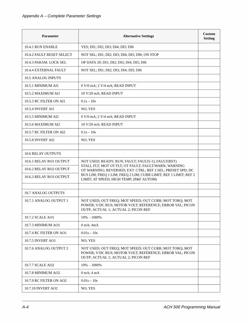
Appendix A – Complete Parameter Settings
A-4 ACH 500 Programming Manual
10.4.1 RUN ENABLE YES; DI1; DI2; DI3; DI4; DI5; DI6
10.4.2 FAULT RESET SELECT NOT SEL; DI1; DI2; DI3; DI4; DI5; DI6; ON STOP
10.4.3 PARAM. LOCK SEL OP DATA 20; DI1; DI2; DI3; DI4; DI5; DI6
10.4.4 EXTERNAL FAULT NOT SEL; DI1; DI2; DI3; DI4; DI5; DI6
10.5 ANALOG INPUTS
10.5.1 MINIMUM AI1 0 V/0 mA; 2 V/4 mA; READ INPUT
10.5.2 MAXIMUM AI1 10 V/20 mA; READ INPUT
10.5.3 RC FILTER ON AI1 0.1s – 10s
10.5.4 INVERT AI1 NO; YES
10.5.5 MINIMUM AI2 0 V/0 mA; 2 V/4 mA; READ INPUT
10.5.6 MAXIMUM AI2 10 V/20 mA; READ INPUT
10.5.7 RC FILTER ON AI2 0.1s – 10s
10.5.8 INVERT AI2 NO; YES
10.6 RELAY OUTPUTS
10.6.1 RELAY RO1 OUTPUT NOT USED; READY; RUN; FAULT; FAULT(-1); FAULT(RST)STALL FLT; MOT OT FLT; OT FAULT; FAULT/WARN; WARNINGOT WARNING; REVERSED; EXT. CTRL; REF 2 SEL; PRESET SPD; DC BUS LIM; FREQ 1 LIM; FREQ 2 LIM; CURR LIMIT; REF 1 LIMIT; REF 2 LIMIT; AT SPEED; HIGH TEMP; (P&F AUTOM)
10.6.2 RELAY RO2 OUTPUT
10.6.3 RELAY RO3 OUTPUT
10.7 ANALOG OUTPUTS
10.7.1 ANALOG OUTPUT 1 NOT USED; OUT FREQ; MOT SPEED; OUT CURR; MOT TORQ; MOT POWER; V/DC BUS; MOTOR VOLT; REFERENCE; ERROR VAL; PICON OUTP; ACTUAL 1; ACTUAL 2; PICON REF
10.7.2 SCALE AO1 10% – 1000%
10.7.3 MINIMUM AO1 0 mA; 4mA
10.7.4 RC FILTER ON AO1 0.01s – 10s
10.7.5 INVERT AO1 NO; YES
10.7.6 ANALOG OUTPUT 2 NOT USED; OUT FREQ; MOT SPEED; OUT CURR; MOT TORQ; MOT POWER; V/DC BUS; MOTOR VOLT; REFERENCE; ERROR VAL; PICON OUTP; ACTUAL 1; ACTUAL 2; PICON REF
10.7.7 SCALE AO2 10% – 1000%
10.7.8 MINIMUM AO2 0 mA; 4 mA
10.7.9 RC FILTER ON AO2 0.01s – 10s
10.7.10 INVERT AO2 NO; YES
Parameter Alternative SettingsCustom Setting
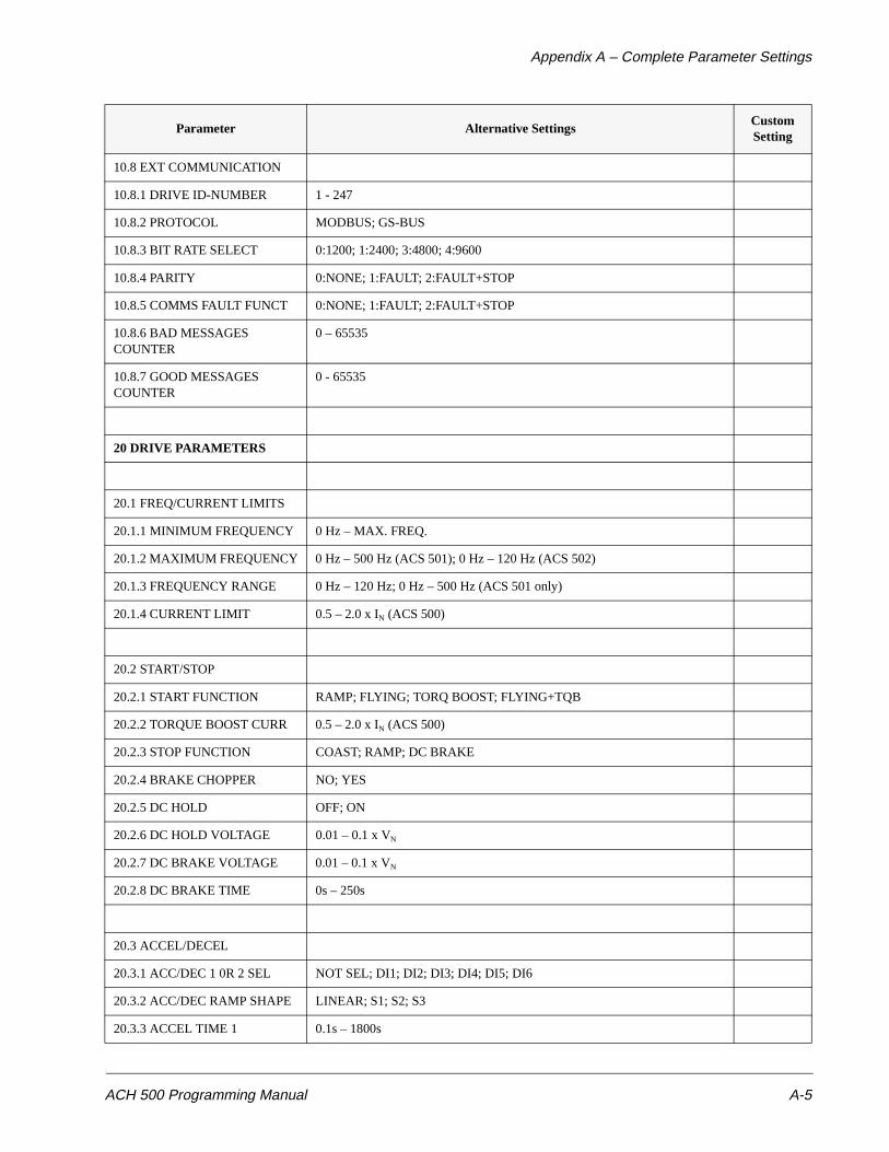
Appendix A – Complete Parameter Settings
ACH 500 Programming Manual A-5
10.8 EXT COMMUNICATION
10.8.1 DRIVE ID-NUMBER 1 - 247
10.8.2 PROTOCOL MODBUS; GS-BUS
10.8.3 BIT RATE SELECT 0:1200; 1:2400; 3:4800; 4:9600
10.8.4 PARITY 0:NONE; 1:FAULT; 2:FAULT+STOP
10.8.5 COMMS FAULT FUNCT 0:NONE; 1:FAULT; 2:FAULT+STOP
10.8.6 BAD MESSAGES COUNTER
0 – 65535
10.8.7 GOOD MESSAGES COUNTER
0 - 65535
20 DRIVE PARAMETERS
20.1 FREQ/CURRENT LIMITS
20.1.1 MINIMUM FREQUENCY 0 Hz – MAX. FREQ.
20.1.2 MAXIMUM FREQUENCY 0 Hz – 500 Hz (ACS 501); 0 Hz – 120 Hz (ACS 502)
20.1.3 FREQUENCY RANGE 0 Hz – 120 Hz; 0 Hz – 500 Hz (ACS 501 only)
20.1.4 CURRENT LIMIT 0.5 – 2.0 x IN (ACS 500)
20.2 START/STOP
20.2.1 START FUNCTION RAMP; FLYING; TORQ BOOST; FLYING+TQB
20.2.2 TORQUE BOOST CURR 0.5 – 2.0 x IN (ACS 500)
20.2.3 STOP FUNCTION COAST; RAMP; DC BRAKE
20.2.4 BRAKE CHOPPER NO; YES
20.2.5 DC HOLD OFF; ON
20.2.6 DC HOLD VOLTAGE 0.01 – 0.1 x VN
20.2.7 DC BRAKE VOLTAGE 0.01 – 0.1 x VN
20.2.8 DC BRAKE TIME 0s – 250s
20.3 ACCEL/DECEL
20.3.1 ACC/DEC 1 0R 2 SEL NOT SEL; DI1; DI2; DI3; DI4; DI5; DI6
20.3.2 ACC/DEC RAMP SHAPE LINEAR; S1; S2; S3
20.3.3 ACCEL TIME 1 0.1s – 1800s
Parameter Alternative SettingsCustom Setting
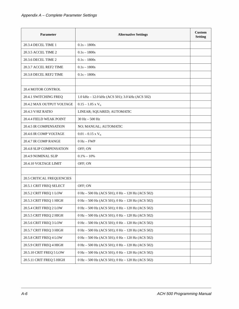
Appendix A – Complete Parameter Settings
A-6 ACH 500 Programming Manual
20.3.4 DECEL TIME 1 0.1s – 1800s
20.3.5 ACCEL TIME 2 0.1s – 1800s
20.3.6 DECEL TIME 2 0.1s – 1800s
20.3.7 ACCEL REF2 TIME 0.1s – 1800s
20.3.8 DECEL REF2 TIME 0.1s – 1800s
20.4 MOTOR CONTROL
20.4.1 SWITCHING FREQ 1.0 kHz – 12.0 kHz (ACS 501); 3.0 kHz (ACS 502)
20.4.2 MAX OUTPUT VOLTAGE 0.15 – 1.05 x VN
20.4.3 V/HZ RATIO LINEAR; SQUARED; AUTOMATIC
20.4.4 FIELD WEAK POINT 30 Hz – 500 Hz
20.4.5 IR COMPENSATION NO; MANUAL; AUTOMATIC
20.4.6 IR COMP VOLTAGE 0.01 – 0.15 x VN
20.4.7 IR COMP RANGE 0 Hz – FWP
20.4.8 SLIP COMPENSATION OFF; ON
20.4.9 NOMINAL SLIP 0.1% – 10%
20.4.10 VOLTAGE LIMIT OFF; ON
20.5 CRITICAL FREQUENCIES
20.5.1 CRIT FREQ SELECT OFF; ON
20.5.2 CRIT FREQ 1 LOW 0 Hz – 500 Hz (ACS 501); 0 Hz – 120 Hz (ACS 502)
20.5.3 CRIT FREQ 1 HIGH 0 Hz – 500 Hz (ACS 501); 0 Hz – 120 Hz (ACS 502)
20.5.4 CRIT FREQ 2 LOW 0 Hz – 500 Hz (ACS 501); 0 Hz – 120 Hz (ACS 502)
20.5.5 CRIT FREQ 2 HIGH 0 Hz – 500 Hz (ACS 501); 0 Hz – 120 Hz (ACS 502)
20.5.6 CRIT FREQ 3 LOW 0 Hz – 500 Hz (ACS 501); 0 Hz – 120 Hz (ACS 502)
20.5.7 CRIT FREQ 3 HIGH 0 Hz – 500 Hz (ACS 501); 0 Hz – 120 Hz (ACS 502)
20.5.8 CRIT FREQ 4 LOW 0 Hz – 500 Hz (ACS 501); 0 Hz – 120 Hz (ACS 502)
20.5.9 CRIT FREQ 4 HIGH 0 Hz – 500 Hz (ACS 501); 0 Hz – 120 Hz (ACS 502)
20.5.10 CRIT FREQ 5 LOW 0 Hz – 500 Hz (ACS 501); 0 Hz – 120 Hz (ACS 502)
20.5.11 CRIT FREQ 5 HIGH 0 Hz – 500 Hz (ACS 501); 0 Hz – 120 Hz (ACS 502)
Parameter Alternative SettingsCustom Setting
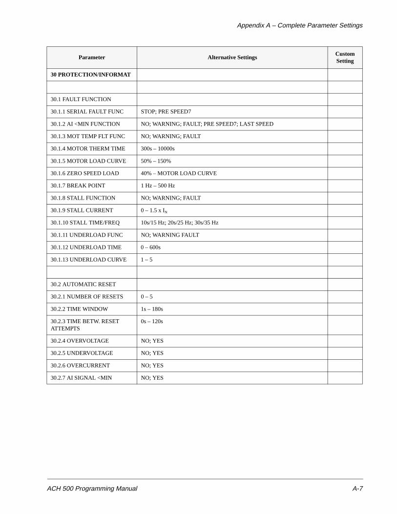
Appendix A – Complete Parameter Settings
ACH 500 Programming Manual A-7
30 PROTECTION/INFORMAT
30.1 FAULT FUNCTION
30.1.1 SERIAL FAULT FUNC STOP; PRE SPEED7
30.1.2 AI <MIN FUNCTION NO; WARNING; FAULT; PRE SPEED7; LAST SPEED
30.1.3 MOT TEMP FLT FUNC NO; WARNING; FAULT
30.1.4 MOTOR THERM TIME 300s – 10000s
30.1.5 MOTOR LOAD CURVE 50% – 150%
30.1.6 ZERO SPEED LOAD 40% – MOTOR LOAD CURVE
30.1.7 BREAK POINT 1 Hz – 500 Hz
30.1.8 STALL FUNCTION NO; WARNING; FAULT
30.1.9 STALL CURRENT 0 – 1.5 x IN
30.1.10 STALL TIME/FREQ 10s/15 Hz; 20s/25 Hz; 30s/35 Hz
30.1.11 UNDERLOAD FUNC NO; WARNING FAULT
30.1.12 UNDERLOAD TIME 0 – 600s
30.1.13 UNDERLOAD CURVE 1 – 5
30.2 AUTOMATIC RESET
30.2.1 NUMBER OF RESETS 0 – 5
30.2.2 TIME WINDOW 1s – 180s
30.2.3 TIME BETW. RESET ATTEMPTS
0s – 120s
30.2.4 OVERVOLTAGE NO; YES
30.2.5 UNDERVOLTAGE NO; YES
30.2.6 OVERCURRENT NO; YES
30.2.7 AI SIGNAL <MIN NO; YES
Parameter Alternative SettingsCustom Setting
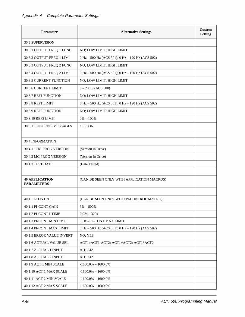
Appendix A – Complete Parameter Settings
A-8 ACH 500 Programming Manual
30.3 SUPERVISION
30.3.1 OUTPUT FREQ 1 FUNC NO; LOW LIMIT; HIGH LIMIT
30.3.2 OUTPUT FREQ 1 LIM 0 Hz – 500 Hz (ACS 501); 0 Hz – 120 Hz (ACS 502)
30.3.3 OUTPUT FREQ 2 FUNC NO; LOW LIMIT; HIGH LIMIT
30.3.4 OUTPUT FREQ 2 LIM 0 Hz – 500 Hz (ACS 501); 0 Hz – 120 Hz (ACS 502)
30.3.5 CURRENT FUNCTION NO; LOW LIMIT; HIGH LIMIT
30.3.6 CURRENT LIMIT 0 – 2 x IN (ACS 500)
30.3.7 REF1 FUNCTION NO; LOW LIMIT; HIGH LIMIT
30.3.8 REF1 LIMIT 0 Hz – 500 Hz (ACS 501); 0 Hz – 120 Hz (ACS 502)
30.3.9 REF2 FUNCTION NO; LOW LIMIT; HIGH LIMIT
30.3.10 REF2 LIMIT 0% – 100%
30.3.11 SUPERVIS MESSAGES OFF; ON
30.4 INFORMATION
30.4.11 CRI PROG VERSION (Version in Drive)
30.4.2 MC PROG VERSION (Version in Drive)
30.4.3 TEST DATE (Date Tested)
40 APPLICATION PARAMETERS
(CAN BE SEEN ONLY WITH APPLICATION MACROS)
40.1 PI-CONTROL (CAN BE SEEN ONLY WITH PI-CONTROL MACRO)
40.1.1 PI-CONT GAIN 3% – 800%
40.1.2 PI-CONT I-TIME 0.02s – 320s
40.1.3 PI-CONT MIN LIMIT 0 Hz – PI-CONT MAX LIMIT
40.1.4 PI-CONT MAX LIMIT 0 Hz – 500 Hz (ACS 501); 0 Hz – 120 Hz (ACS 502)
40.1.5 ERROR VALUE INVERT NO; YES
40.1.6 ACTUAL VALUE SEL ACT1; ACT1-ACT2; ACT1+ACT2; ACT1*ACT2
40.1.7 ACTUAL 1 INPUT AI1; AI2
40.1.8 ACTUAL 2 INPUT AI1; AI2
40.1.9 ACT 1 MIN SCALE -1600.0% – 1600.0%
40.1.10 ACT 1 MAX SCALE -1600.0% – 1600.0%
40.1.11 ACT 2 MIN SCALE -1600.0% – 1600.0%
40.1.12 ACT 2 MAX SCALE -1600.0% – 1600.0%
Parameter Alternative SettingsCustom Setting
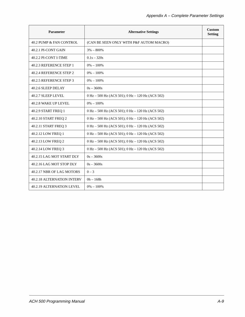
Appendix A – Complete Parameter Settings
ACH 500 Programming Manual A-9
40.2 PUMP & FAN CONTROL (CAN BE SEEN ONLY WITH P&F AUTOM MACRO)
40.2.1 PI-CONT GAIN 3% – 800%
40.2.2 PI-CONT I-TIME 0.1s – 320s
40.2.3 REFERENCE STEP 1 0% – 100%
40.2.4 REFERENCE STEP 2 0% – 100%
40.2.5 REFERENCE STEP 3 0% – 100%
40.2.6 SLEEP DELAY 0s – 3600s
40.2.7 SLEEP LEVEL 0 Hz – 500 Hz (ACS 501); 0 Hz – 120 Hz (ACS 502)
40.2.8 WAKE UP LEVEL 0% – 100%
40.2.9 START FREQ 1 0 Hz – 500 Hz (ACS 501); 0 Hz – 120 Hz (ACS 502)
40.2.10 START FREQ 2 0 Hz – 500 Hz (ACS 501); 0 Hz – 120 Hz (ACS 502)
40.2.11 START FREQ 3 0 Hz – 500 Hz (ACS 501); 0 Hz – 120 Hz (ACS 502)
40.2.12 LOW FREQ 1 0 Hz – 500 Hz (ACS 501); 0 Hz – 120 Hz (ACS 502)
40.2.13 LOW FREQ 2 0 Hz – 500 Hz (ACS 501); 0 Hz – 120 Hz (ACS 502)
40.2.14 LOW FREQ 3 0 Hz – 500 Hz (ACS 501); 0 Hz – 120 Hz (ACS 502)
40.2.15 LAG MOT START DLY 0s – 3600s
40.2.16 LAG MOT STOP DLY 0s – 3600s
40.2.17 NBR OF LAG MOTORS 0 – 3
40.2.18 ALTERNATION INTERV 0h – 168h
40.2.19 ALTERNATION LEVEL 0% – 100%
Parameter Alternative SettingsCustom Setting
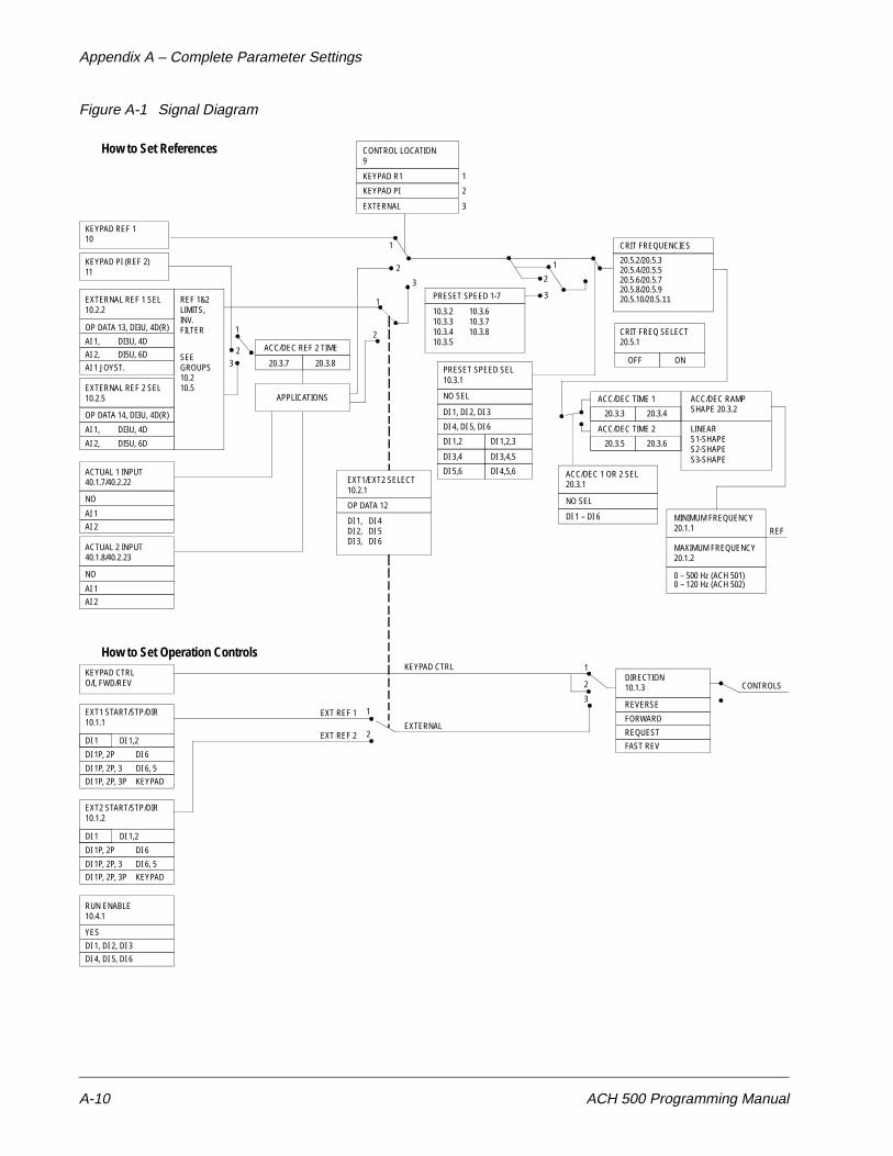
Appendix A – Complete Parameter Settings
A-10 ACH 500 Programming Manual
Figure A-1 Signal Diagram
CONTROL LOCATION9
KEYPAD R1
KEYPAD PI
EXTERNAL
1
2
3
KEYPAD REF 110
KEYPAD PI (REF 2)11
EXTERNAL REF 1 SEL10.2.2
OP DATA 13, DI3U, 4D(R)
AI 1, DI3U, 4D
AI 2, DI5U, 6D
AI 1 JOYST.
EXTERNAL REF 2 SEL10.2.5
OP DATA 14, DI3U, 4D(R)
AI 1, DI3U, 4D
AI 2, DI5U, 6D
ACTUAL 1 INPUT40.1.7/40.2.22
NO
AI 1
AI 2
REF 1&2LIMITS,INV.FILTER
SEEGROUPS10.210.5
ACTUAL 2 INPUT40.1.8/40.2.23
NO
AI 1
AI 2
1
23
ACC/DEC REF 2 TIME
20.3.7 20.3.8
APPLICATIONS
PRESET SPEED 1-7
10.3.210.3.310.3.410.3.5
10.3.610.3.710.3.8
PRESET SPEED SEL10.3.1
NO SEL
DI 1, DI 2, DI 3
DI 4, DI 5, DI 6
DI 1,2
DI 3,4
DI 5,6
DI 1,2,3
DI 3,4,5
DI 4,5,6
CRIT FREQUENCIES
20.5.2/20.5.3
CRIT FREQ SELECT20.5.1
OFF ON
ACC/DEC TIME 1
20.3.3 20.3.4
ACC/DEC TIME 2
20.3.5 20.3.6
ACC/DEC RAMPSHAPE 20.3.2
LINEARS1-SHAPES2-SHAPES3-SHAPE
ACC/DEC 1 OR 2 SEL20.3.1EXT1/EXT2 SELECT
10.2.1
OP DATA 12
DI 1,DI 2,DI 3,
DI 4DI 5DI 6
NO SEL
DI 1 – DI 6 MINIMUM FREQUENCY20.1.1
MAXIMUM FREQUENCY20.1.2
0 – 500 Hz (ACH 501)
REF
CONTROLSDIRECTION10.1.3
REVERSE
FORWARD
REQUEST
FAST REV
1
2
3
KEYPAD CTRL
EXTERNAL
EXT REF 1
EXT REF 2
1
2
KEYPAD CTRLO/I, FWD/REV
EXT1 START/STP/DIR10.1.1
DI 1 DI 1,2
DI 1P, 2P
DI 1P, 2P, 3
DI 1P, 2P, 3P
RUN ENABLE10.4.1
YES
DI 1, DI 2, DI 3
DI 4, DI 5, DI 6
How to Set References
How to Set Operation Controls
1
2
3
1
2
1
2
3
20.5.4/20.5.520.5.6/20.5.720.5.8/20.5.920.5.10/20.5.11
DI 6
DI 6, 5
KEYPAD
EXT2 START/STP/DIR10.1.2
DI 1 DI 1,2
DI 1P, 2P
DI 1P, 2P, 3
DI 1P, 2P, 3P
DI 6
DI 6, 5
KEYPAD
0 – 120 Hz (ACH 502)
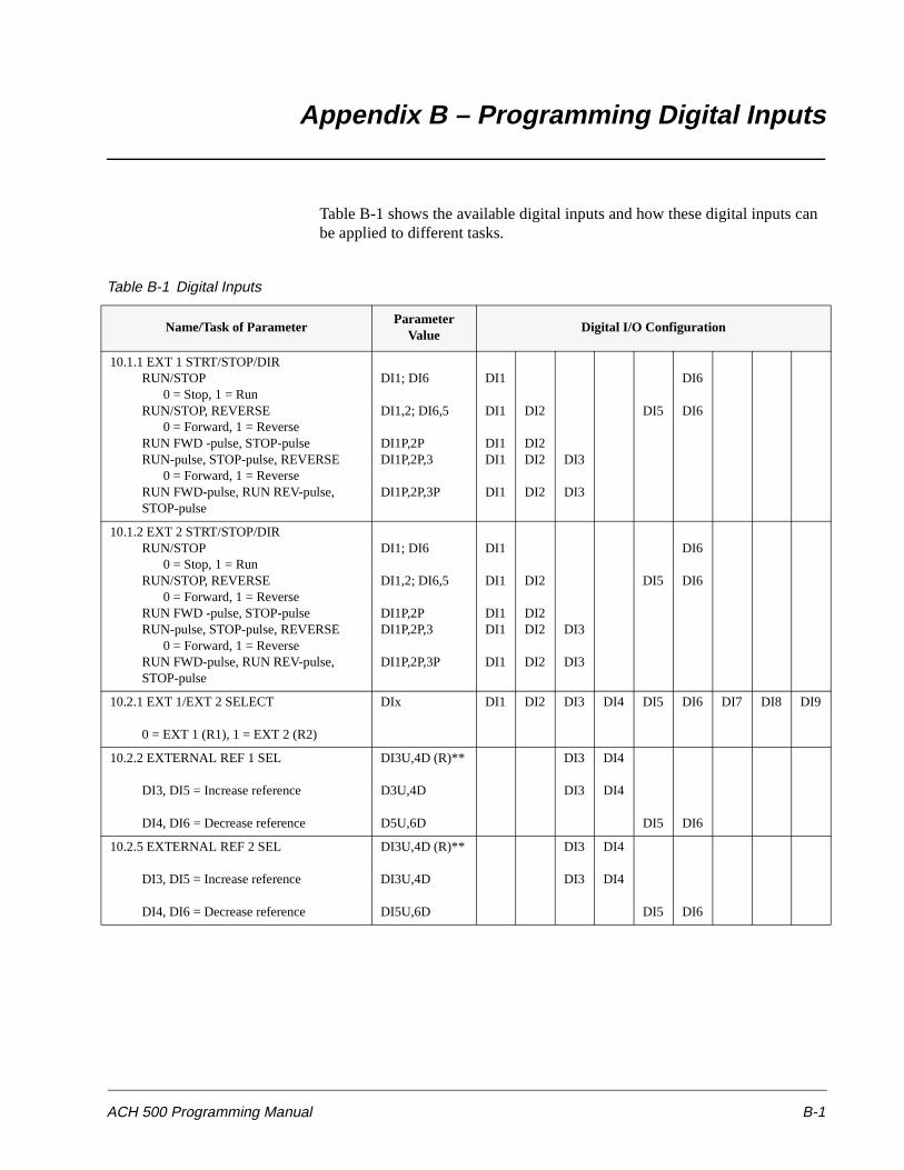
ACH 500 Programming Manual B-1
Appendix B – Programming Digital Inputs
Table B-1 shows the available digital inputs and how these digital inputs can be applied to different tasks.
Table B-1 Digital Inputs
Name/Task of ParameterParameter
ValueDigital I/O Configuration
10.1.1 EXT 1 STRT/STOP/DIRRUN/STOP
0 = Stop, 1 = RunRUN/STOP, REVERSE
0 = Forward, 1 = ReverseRUN FWD -pulse, STOP-pulseRUN-pulse, STOP-pulse, REVERSE
0 = Forward, 1 = ReverseRUN FWD-pulse, RUN REV-pulse,STOP-pulse
DI1; DI6
DI1,2; DI6,5
DI1P,2PDI1P,2P,3
DI1P,2P,3P
DI1
DI1
DI1DI1
DI1
DI2
DI2DI2
DI2
DI3
DI3
DI5
DI6
DI6
10.1.2 EXT 2 STRT/STOP/DIRRUN/STOP
0 = Stop, 1 = RunRUN/STOP, REVERSE
0 = Forward, 1 = ReverseRUN FWD -pulse, STOP-pulseRUN-pulse, STOP-pulse, REVERSE
0 = Forward, 1 = ReverseRUN FWD-pulse, RUN REV-pulse,STOP-pulse
DI1; DI6
DI1,2; DI6,5
DI1P,2PDI1P,2P,3
DI1P,2P,3P
DI1
DI1
DI1DI1
DI1
DI2
DI2DI2
DI2
DI3
DI3
DI5
DI6
DI6
10.2.1 EXT 1/EXT 2 SELECT
0 = EXT 1 (R1), 1 = EXT 2 (R2)
DIx DI1 DI2 DI3 DI4 DI5 DI6 DI7 DI8 DI9
10.2.2 EXTERNAL REF 1 SEL
DI3, DI5 = Increase reference
DI4, DI6 = Decrease reference
DI3U,4D (R)**
D3U,4D
D5U,6D
DI3
DI3
DI4
DI4
DI5 DI6
10.2.5 EXTERNAL REF 2 SEL
DI3, DI5 = Increase reference
DI4, DI6 = Decrease reference
DI3U,4D (R)**
DI3U,4D
DI5U,6D
DI3
DI3
DI4
DI4
DI5 DI6
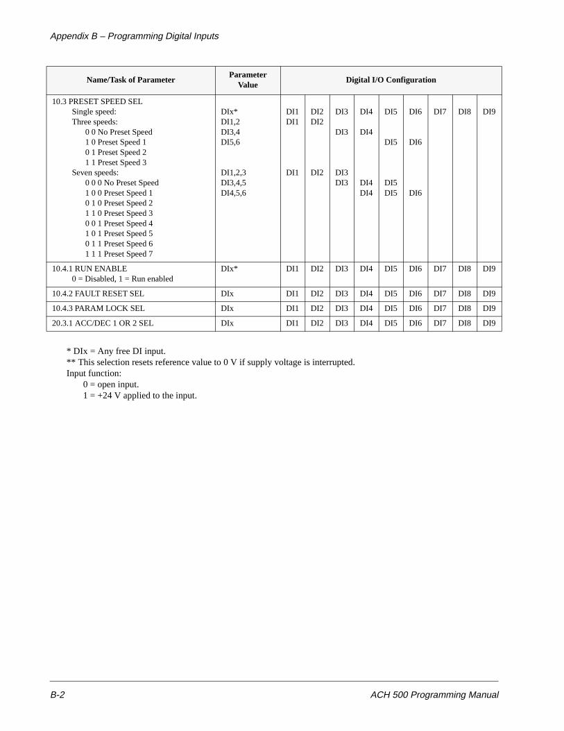
Appendix B – Programming Digital Inputs
B-2 ACH 500 Programming Manual
* DIx = Any free DI input.** This selection resets reference value to 0 V if supply voltage is interrupted.Input function:
0 = open input.1 = +24 V applied to the input.
10.3 PRESET SPEED SELSingle speed:Three speeds:
0 0 No Preset Speed1 0 Preset Speed 10 1 Preset Speed 21 1 Preset Speed 3
Seven speeds:0 0 0 No Preset Speed1 0 0 Preset Speed 10 1 0 Preset Speed 21 1 0 Preset Speed 30 0 1 Preset Speed 41 0 1 Preset Speed 50 1 1 Preset Speed 61 1 1 Preset Speed 7
DIx*DI1,2DI3,4DI5,6
DI1,2,3DI3,4,5DI4,5,6
DI1DI1
DI1
DI2DI2
DI2
DI3
DI3
DI3DI3
DI4
DI4
DI4DI4
DI5
DI5
DI5DI5
DI6
DI6
DI6
DI7 DI8 DI9
10.4.1 RUN ENABLE0 = Disabled, 1 = Run enabled
DIx* DI1 DI2 DI3 DI4 DI5 DI6 DI7 DI8 DI9
10.4.2 FAULT RESET SEL DIx DI1 DI2 DI3 DI4 DI5 DI6 DI7 DI8 DI9
10.4.3 PARAM LOCK SEL DIx DI1 DI2 DI3 DI4 DI5 DI6 DI7 DI8 DI9
20.3.1 ACC/DEC 1 OR 2 SEL DIx DI1 DI2 DI3 DI4 DI5 DI6 DI7 DI8 DI9
Name/Task of ParameterParameter
ValueDigital I/O Configuration

ACH 500 Programming Manual I-1
Index
A
ACC/DEC 1OR2 SEL 6-20ACC/DEC RAMP SHAPE 6-20ACCEL REF2 TIME 6-22ACCEL TIME 1 6-21ACCEL TIME 2 6-21Accel/decel 6-20Acceleration time 6-20ACT 1 MAX SCALE 6-43, 6-52ACT 1 MIN SCALE 6-43, 6-52ACT 2 MAX SCALE 6-44, 6-53ACT 2 MIN SCALE 6-44, 6-53ACTUAL 1 INPUT 6-42, 6-51ACTUAL 2 INPUT 6-42, 6-52ACTUAL VALUE 6-42ACTUAL VALUE SEL 6-52AI MIN FUNCTION 6-31AI SIGNAL 6-38ALTERNATION INTERV. 6-50ALTERNATION LEVEL 6-50Analog input
filtering 6-10scaling 6-10
Analog inputs 6-4, 6-10ANALOG OUTPUT 6-14Analog output
filtering 6-15scaling 6-15
ANALOG OUTPUT 2 6-15Analog outputs 6-14, 6-15APPLIC. RESTORE 3-2Application macros 5-1
floating point control 5-6HVAC 5-3HVAC defaults 2-8HVAC-PI 5-9overview 2-8pump and fan 5-12
Application macros, defined 2-1APPLICATIONS 3-2Audience, intended 1-2Automatic reset 6-37Automatic V/Hz 6-24
B
Boost 6-18BRAKE CHOPPER 6-18BREAK POINT 6-34BYPASS CONTROL 6-53
C
Carrier frequency 6-23Cautions, definition iiiCoast stop 6-18Control connection parameters 6-2Control interface card, ESD warning ivCONTROL LOCATION 4-3, 4-4Control operations
external 4-7keypad 4-7
Control paneldisplay illustrated 1-2keypad menu navigation 2-3keys illustrated 1-3
Conventions used in this manual 1-2CRI PROG VERSION 6-40Critical frequencies 6-28CURRENT FUNCTION 6-39CURRENT LIMIT 6-17, 6-39
D
DC BRAKE TIME 6-19DC BRAKE VOLTAGE 6-19DC bus capacitors ivDC HOLD 6-18DC HOLD VOLTAGE 6-19DC Injection braking 6-18, 6-19DECEL REF2 TIME 6-22DECEL TIME 1 6-21DECEL TIME 2 6-22Deceleration time 6-20Digital inputs, programming B-1Digital outputs 6-12DIRECTION 6-3Direction 6-2, 6-3, 6-8DISPL UNIT SCALE 6-54DISPLAY UNIT 6-54
Index
I-2 ACH 500 Programming Manual
E
Eprom version 6-40ERROR VALUE INV. 6-51ERROR VALUE INVERT 6-42ESD warning ivEXT 1/EXT 2 SELECT 6-4Ext communication 6-16EXT REF1 MAXIMUM 6-6EXT REF1 MINIMUM 6-6EXT REF2 MAXIMUM 6-6EXT REF2 MINIMUM 6-6EXT1 STRT/STP/DIR 6-2EXT2 STRT/STP/DIR 6-3External control 4-7EXTERNAL FAULT 6-9EXTERNAL REF1 SEL 6-4EXTERNAL REF2 SEL 6-6External reference 1 4-10External reference 2 4-10
F
Fault functions 6-30FAULT RESET SELECT 6-9Field weakening point 6-24Floating point control macro 5-6
external connections 5-7parameter settings 5-8
Flying start 6-17Forward 6-2, 6-3, 6-8Freq/current limits 6-16FREQUENCY RANGE 6-16
G
Group 10.1 start/stop/direction 6-2Group 10.2 reference select 6-4Group 10.3 preset speeds 6-7Group 10.4 system contr inputs 6-9Group 10.5 analog inputs 6-10Group 10.6 relay outputs 6-12Group 10.7 analog outputs 6-14Group 10.8 ext communication 6-16Group 20.1 freq/current limits 6-16Group 20.2 start/stop 6-17Group 20.3 accel/decel 6-20Group 20.4 motor control 6-22Group 20.5 crit frequencies 6-28Group 30.1 fault functions 6-30Group 30.2 automatic reset 6-37
Group 30.3 supervision 6-38Group 30.4 information 6-40Group 40.1 PI-controller 6-41Group 40.2 pump and fan control 6-45Group level
access 2-5defined 2-5illustrated 2-5
H
HVAC macro 5-3external connections 5-4parameter settings 5-5
HVAC-PI macro 5-9external connections 5-10parameter settings 5-11
I
I2t 6-31Information 6-40INTERLOCKS 6-51INVERT AI1 6-11INVERT AI2 6-11INVERT AO1 6-15INVERT AO2 6-15IR COMPENSATION 6-25IR-COMP RANGE 6-26IR-COMP VOLTAGE 6-26
K
Keypad control 4-7Keypad PI 4-9Keypad reference 1 4-9
L
LAG MOT START DLY 6-50LAG MOT STOP DLY 6-50LANGUAGE 3-2Living zero 6-10, 6-31LOW FREQ 1 6-49LOW FREQ 2 6-50LOW FREQ 3 6-50
M
Macrosaccess 5-2applications 5-2
Index
ACH 500 Programming Manual I-3
Macros, defined 2-1Main 10 control connection parameters 6-2Main 20 drive parameters 6-16Main 30 protection parameters 6-30Main 40 application parameters 6-41Main level
access 2-4defined 2-4illustrated 2-4
Manualconventions 1-2how to use 1-1
MAX OUTPUT VOLTAGE 6-23MAXIMUM AI1 6-10MAXIMUM AI2 6-11MAXIMUM FREQUENCY 6-16MC PROG VERSION 6-40Menu system
described 2-2illustrated 2-2navigation 2-3
MINIMUM AI1 6-10MINIMUM AI2 6-11MINIMUM AO1 6-15MINIMUM AO2 6-15MINIMUM FREQUENCY 6-16MOT TEMP FLT FUNC 6-31MOTOR BASE FREQUENCY 3-3MOTOR BASE R.P.M. 3-3Motor control 6-22Motor control card
ESD warning ivMotor control values 4-6MOTOR CURRENT -FLA 3-3MOTOR LOAD CURVE 6-34MOTOR NOM. VOLTAGE 3-3Motor overload protection 6-31MOTOR POWER 3-3MOTOR POWER FACTOR 3-3MOTOR THERM TIME 6-33
N
NBR OF DECIMALS 6-54NBR OF LAG MOTORS 6-50NOMINAL SLIP 6-27Notes, definition iiiNUMBER OF RESETS 6-37
O
Operating dataaccess 4-3functions 4-1overview 2-3parameter selection 4-3parameters defined 4-1parameters listed 4-2
OUTPUT FREQ 1 FUNC 6-39OUTPUT FREQ 1 LIMIT 6-39OUTPUT FREQ 2 FUNC 6-39OUTPUT FREQ 2 LIMIT 6-39OVERCURRENT 6-38OVERVOLTAGE 6-37
P
PARAM. LOCK SEL 6-9Parameter
menus 6-1selection illustrated 2-7
Parameter levelaccess 2-6changing values 2-6defined 2-6illustrated 2-6
Parameter lock 4-5, 4-10, 6-9Parameters
alternate settings A-1listed A-1motor control values 4-6operating data 4-1overview 6-1
Parameters, menu system 2-2defined 2-2illustrated 2-2, 6-1navigation 2-3start-up data 2-2
PI-CONT GAIN 6-41, 6-47PI-CONT I-TIME 6-42, 6-47PI-CONT MAX LIMIT 6-42PI-CONT MIN LIMIT 6-42PI-Controller 6-41PRESET SPEED SEL 6-8Preset speeds 6-7Programming digital inputs B-1Protection parameters 6-30Pump and fan control 6-45
Index
I-4 ACH 500 Programming Manual
Pump and fan macro 5-12external connections 5-13parameter settings 5-14sample application 6-54
R
Ramp shape, accel/decel 6-20RC FILTER ON AI1 6-11RC FILTER ON AI2 6-11RC FILTER ON AO1 6-15RC FILTER ON AO2 6-15REF1 FUNCTION 6-39REF1 LIMIT 6-39REF2 FUNCTION 6-39REF2 LIMIT 6-39Reference select 6-4REFERENCE STEP 1 6-47REFERENCE STEP 2 6-48REFERENCE STEP 3 6-48Relay outputs 6-12RELAY RO1 OUTPUT 6-12RELAY RO2 OUTPUT 6-13RELAY RO3 OUTPUT 6-13Reverse 6-2, 6-3, 6-8RUN ENABLE 6-9
S
Safety instructionsgeneral iiiwarning symbols iii
SCALE AO1 6-15SCALE AO2 6-15S-Curve 6-16SERIAL FAULT FUNC 6-30Signal flow diagram 4-8SLEEP DELAY 6-48Sleep function 6-48SLEEP LEVEL 6-49SLIP COMPENSATION 6-26Squared V/Hz 6-23STALL CURRENT 6-35STALL FUNCTION 6-34STALL TIME/FREQ 6-35START FREQ 1 6-49START FREQ 2 6-49START FUNCTION 6-17Start/stop 6-17Start/stop/direction 6-2
Start-upparameters 3-1
Start-up datadescribed 2-2using the menu 2-3
Start-up data parameters 3-1STOP FUNCTION 6-18SUPERVIS MESSAGES 6-39Supervision 6-38SUPPLY VOLTAGE 3-2SWITCHING FREQ 6-23, 6-24System contr inputs 6-9
T
TEST DATE 6-40TIME BETW. RESET ATTEMPTS 6-37TIME WINDOW 6-37TORQUE BOOST CUR 6-18
U
UNDERLOAD CURVE 6-36UNDERLOAD FUNCTION 6-35UNDERLOAD TIME 6-35UNDERVOLTAGE 6-38USER DISPLAY SCALE 3-2User macro 5-1
V
V/Hz RATIO 6-23V/Hz2 6-23VOLTAGE LIMIT 6-27Voltage regulators 6-27
W
WAKE UP LEVEL 6-49
Z
ZERO SPEED LOAD 6-34

Index
ACH 500 Programming Manual I-5