accessory fitting instructions · accessory fitting instructions ... in loss of motorcycle control...
TRANSCRIPT
Accessory Fitting Instructions
1 of 12Publication part number A9900483 issue 8© Triumph Designs Ltd. 2017
English
Thank you for choosing this Triumph genuine accessory kit. This accessory kit is the product of Triumph's use ofproven engineering, exhaustive testing, and continuous striving for superior reliability, safety and performance.
Completely read all of these instructions before commencing the installation of the accessory kit in order tobecome thoroughly familiar with the kit’s features and the installation process.
These instructions should be considered a permanent part of your accessory kit, and should remain with it evenif your accessory equipped motorcycle is subsequently sold.
Top Box KitKit number Models Affected
T2350297T2351060T2351034T2356830
Tiger Explorer, Tiger Explorer XC, Tiger Explorer XR, Tiger Explorer XRX, Tiger Explorer XRT, Tiger Explorer XC, Tiger Explorer XCX, Tiger Explorer XCA,
A9500748 Tiger 1200 XRX, Tiger 1200 XRX LRH, Tiger 1200 XCX, Tiger 1200 XRT, Tiger 1200 XCA
A9500749 Tiger Explorer, Tiger Explorer XC, Tiger Explorer XR, Tiger Explorer XRX, Tiger Explorer XRT, Tiger Explorer XC, Tiger Explorer XCX, Tiger Explorer XCA,Tiger 1200 XR
To be used with
Sliding Carriage KitKit number Models Affected
A9508162A9508171
Tiger Explorer, Tiger Explorer XC, Tiger Explorer XR, Tiger Explorer XRX, Tiger Explorer XRT, Tiger Explorer XC, Tiger Explorer XCX, Tiger Explorer XCA,Tiger 1200 XR, Tiger 1200 XRX, Tiger 1200 XRX LRH, Tiger 1200 XCX, Tiger 1200 XRT, Tiger 1200 XCA

2 of 12
Parts supplied: A9500748, A9500749, T2350297, T2351060, T2351034, T2356830
1. Top Box 1 off
1

3 of 12
Parts supplied: A9508162, A9508171
1. Sliding carriage assembly 1 off 6. Sub-harness 1 off
2. Bolt, M8 x 40 mm 4 off 7. Screw, self-tapping 3 off
3. Lock nut, M8 4 off 8. Harness cover 1 off
4. Cable tie 1 off 9. Moulding, terminal support 1 off
5. Relay (A9508162 only) 1 off
T0992
1
2
3
46
7
8
2
7
7
9
5

4 of 12
Note:
• The accessory kits A9508162 and A9508171 -sliding carriage must be used in conjunction withtop box A9500748, A9500749, T2350297,T2351060, T2351034 and T2536830.
Sliding Carriage
1. Position the motorcycle on a paddock stand.
2. Remove the rider’s seat as described in theowner's handbook.
3. Disconnect the battery, negative (black) lead first.
4. Remove the four bolts securing the rear rackcover, discarding the lock nuts. Retain the boltsfor reuse if the motorcycle is to be returned toits original condition.
1. Fixings2. Grab rack cover
5. Remove the four fixings and remove the rearrack. Retain the fixings for reuse at a later stage.
1. Front fixings2. Rear fixings
WarningThe accessory kits covered in this instruction aredesigned for use on specific models of Triumphmotorcycle. The accessory kits and the modelsapplicable are listed at the start of the instruction.They should not be fitted to any other Triumphmodel or to any other manufacturer’s motorcycle.Fitting an accessory kit to a Triumph model notlisted, or to any other manufacturer’s motorcyclewill affect the performance, stability and handling ofthe motorcycle. This may result in loss ofmotorcycle control and an accident.
WarningAlways have Triumph approved parts, accessoriesand conversions fitted by a trained technician of anauthorised Triumph dealer. The fitment of parts,accessories and conversions by a technician who isnot of an authorised Triumph dealer may affect thehandling, stability or other aspects of themotorcycle’s operation which may result in loss ofmotorcycle control and an accident.
WarningThroughout this operation, ensure that themotorcycle is stabilized and adequately supportedto prevent risk of injury from the motorcycle falling.
WarningA torque wrench of known accurate calibrationmust be used when fitting this accessory kit. Failureto tighten any of the fasteners to the correcttorque specification may affect motorcycleperformance, handling and stability. This may resultin loss of motorcycle control and an accident.
1
2
T1045
21

5 of 12
6. Remove the rubber grommet, retain it for reuse ifthe motorcycle is to be returned to its originalcondition.
1. Rubber grommet2. Rear panel
7. Remove the rear panel fixings and remove therear panel, retain the fixings for reuse at a laterstage.
1. Fixings2. Rear panel
8. Feed the sub-harness from the kit through thehole in the rear panel and the frame brace, thenconnect it to the main harness connector, asshown below.
1. Sub-harness 2. Sub-harness connector3. Main harness connector
Tiger Explorer and Tiger Explorer XC only9. Fit the relay from the kit into the main harness
connector as shown below.
1. Relay2. Connector
050
2
1
T1046
21
1
T1048
1
2
3
T1049
1
2

6 of 12
All Models10. Refit the rear panel and secure using the fixings
removed earlier. Tighten the fixings to 7 Nm.
11. Fit the sub-harness grommet into the rear panelwhilst allowing 250 mm of electrical cable toprotrude as this will be used later in theinstruction.
1. Rear panel2. Grommet
12. Fit the rear rack and tighten the bolts to 27 Nm.
1. Rear rack2. Bolts3. Sub-harness
13. Locate the sliding carriage, sub-harness, terminalsupport moulding and a self-tapping screw fromthe kit.
14. Slide the connectors on the harness into theircorresponding holes in the underside of thesliding carriage. Ensure that the cables arepositioned as shown below.
1. Red cable2. Black cable
15. Position the terminal support moulding over theharness connectors and secure in position withthe screw. Tighten the screw to 1.5 Nm.
1. Screw2. Moulding
2
1
T1050
2
1
T1051
3
T0996
1 2
T0998
1
2

7 of 12
16. Recover the two remaining self-tapping screwsfrom the kit and fit the harness cover to theunderside of the sliding carriage. Tighten thescrews to 1.5 Nm. Secure the harness to its coverwith the cable tie supplied, as shown below. Trimoff any excess from the cable tie.
1. Harness cover2. Screws3. Harness4. Cable tie
17. Align the sliding carriage to the rear rack, fit thefour bolts and lock nuts from the kit and tightento 27 Nm.
1. Sliding carriage2. Bolts
18. Reconnect the battery, positive (red) lead first.
19. Refit the rider’s seat as described in the owner'shandbook.
20. Remove the motorcycle from the paddock stand.
1
2
3
4
T0988
1
2
WarningThe sliding carriage must be allowed to move fromside to side on the slide plate. If the sliding carriageis not free to move from side to side when the topbox is fitted, the stability and handlingcharacteristics of the motorcycle may be affected,leading to loss of control and an accident.
WarningIf a load is carried on the sliding carriage withoututilizing the top box, it must be securely attached tothe sliding carriage only and not any other part ofthe rear rack. The sliding carriage must be allowedto move from side to side on the slide plate. If thesliding carriage is not free to move from side to sideon the slide plate, the stability and handlingcharacteristics of the motorcycle may be affected,leading to the loss of control and an accident.

8 of 12
Fitting the Lock Barrel to Top Box - A9500749, T2350297, T2351034, T2351060 and T2356830
1. Fit the ignition key into the lock barrel locksupplied with the motorcycle when new.
Note:
• The lock barrel will only fit one way.2. Align the locking device on the lock barrel to the
slot in the lock housing in the top box, asindicated in the illustration below.
1. Slot2. Housing3. Locking device
3. Push the barrel into position in the top box untilit clicks into place.
4. Check the operation of the barrel.
Fitting the Lock Barrel to Top Box - A9500748
1. Fit the ignition key into the lock barrel locksupplied with the motorcycle when new.
2. Turn the ignition key clockwise to remove thelock barrel lock from its protective case.
1. Ignition key2. Lock barrel3. Protective case
21
3
CautionDo not remove the ignition key from the lock barrelwhen the lock barrel has been removed from itsprotective case. If the key is removed when the lock barrel has beenremoved from the protective case the lock barrel willbe in an unstable condition and the internalcomponents will become unassembled and may belost which will prevent fitment of the lock barrel.The ignition key must only be removed when thelock barrel has been fitted into the top box.
3
1
2
9 of 12
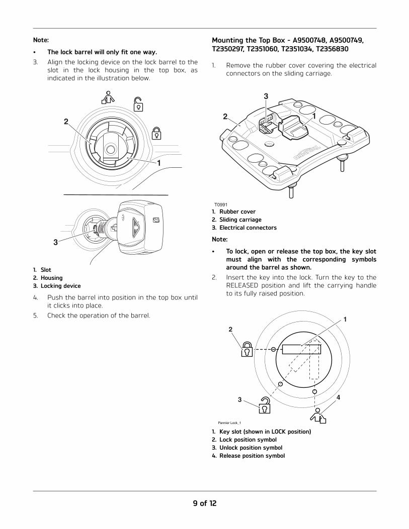
Note:
• The lock barrel will only fit one way.3. Align the locking device on the lock barrel to the
slot in the lock housing in the top box, asindicated in the illustration below.
1. Slot2. Housing3. Locking device
4. Push the barrel into position in the top box untilit clicks into place.
5. Check the operation of the barrel.
Mounting the Top Box - A9500748, A9500749,T2350297, T2351060, T2351034, T2356830
1. Remove the rubber cover covering the electricalconnectors on the sliding carriage.
1. Rubber cover2. Sliding carriage3. Electrical connectors
Note:
• To lock, open or release the top box, the key slotmust align with the corresponding symbolsaround the barrel as shown.
2. Insert the key into the lock. Turn the key to theRELEASED position and lift the carrying handleto its fully raised position.
1. Key slot (shown in LOCK position)2. Lock position symbol3. Unlock position symbol4. Release position symbol
2
1
3
T0991
12
3
2
3 4
1
Pannier Lock_1
10 of 12
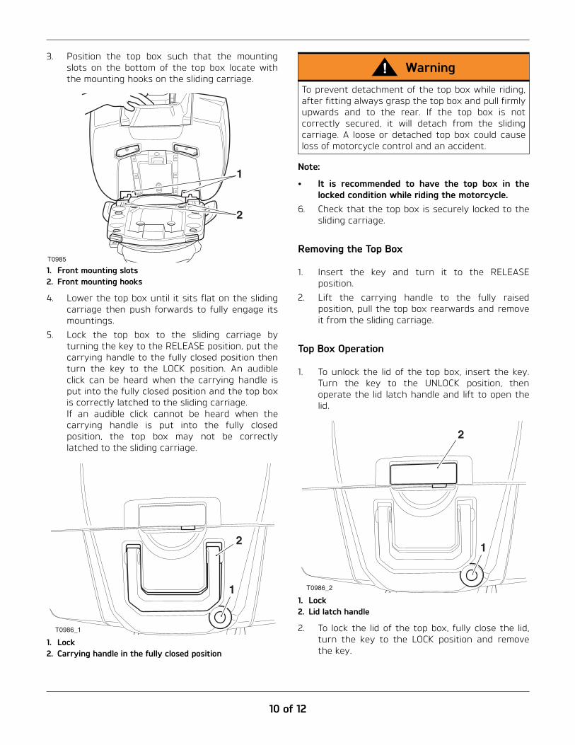
3. Position the top box such that the mountingslots on the bottom of the top box locate withthe mounting hooks on the sliding carriage.
1. Front mounting slots2. Front mounting hooks
4. Lower the top box until it sits flat on the slidingcarriage then push forwards to fully engage itsmountings.
5. Lock the top box to the sliding carriage byturning the key to the RELEASE position, put thecarrying handle to the fully closed position thenturn the key to the LOCK position. An audibleclick can be heard when the carrying handle isput into the fully closed position and the top boxis correctly latched to the sliding carriage.If an audible click cannot be heard when thecarrying handle is put into the fully closedposition, the top box may not be correctlylatched to the sliding carriage.
1. Lock2. Carrying handle in the fully closed position
Note:
• It is recommended to have the top box in thelocked condition while riding the motorcycle.
6. Check that the top box is securely locked to thesliding carriage.
Removing the Top Box
1. Insert the key and turn it to the RELEASEposition.
2. Lift the carrying handle to the fully raisedposition, pull the top box rearwards and removeit from the sliding carriage.
Top Box Operation
1. To unlock the lid of the top box, insert the key.Turn the key to the UNLOCK position, thenoperate the lid latch handle and lift to open thelid.
1. Lock2. Lid latch handle
2. To lock the lid of the top box, fully close the lid,turn the key to the LOCK position and removethe key.
T0985
1
2
T0986_1
1
2
WarningTo prevent detachment of the top box while riding,after fitting always grasp the top box and pull firmlyupwards and to the rear. If the top box is notcorrectly secured, it will detach from the slidingcarriage. A loose or detached top box could causeloss of motorcycle control and an accident.
T0986_2
1
2

11 of 12
Top Box Auxiliary Power Socket
Tiger Explorer and Tiger Explorer XC only
Note:
• Power is only supplied to the top box auxiliarypower socket when the ignition is turned to theON position.
Fuse number 5 (10 A) protects the auxiliary powersocket on the motorcycle, heated grips and theauxiliary power socket in the top box when fitted.
Explorer XR, Explorer XRx, Explorer XRT, Explorer XC, Explorer XCx and Explorer XCA,Tiger 1200 XR, Tiger 1200 XRX, Tiger 1200 XRX LRH, Tiger 1200 XCX, Tiger 1200 XRT, Tiger 1200 XCA
Note:
• Power is only supplied to the auxiliary powersocket when the engine is running.
The top box auxiliary power socket is protected by achassis ECM, which will automatically cut power to thesocket in the event of an overload. Power can berestored to the top box auxiliary power socket byturning the ignition switch off then on again, providedthat the socket is not still overloaded.
In the event of a more serious overload, fuse numberPS4 (25 A) protects the top box auxiliary powersocket, rear auxiliary power socket, heated grips andheated seats when fitted.
WarningThe maximum safe load for the top box, when fittedis 10 kg (22 lbs). Never exceed this loading limit asthis may cause the motorcycle to become unstable,leading to loss of control and an accident.
WarningAlways ensure that any load carried in the top boxis correctly secured such that it will not movearound while the motorcycle is in motion.
Never exceed the maximum vehicle loading weightwhich is described in the owner's handbook.
Incorrect loading may result in an unsafe ridingcondition, which could lead to loss of motorcyclecontrol and an accident.
WarningTo maintain the handling characteristics of themotorcycle when riding with luggage or with apassenger and luggage, refer to the owner'shandbook for the correct suspension settings.
Incorrect suspension settings could significantlychange the handling characteristics of themotorcycle, leading to loss of motorcycle controland an accident.
WarningAfter fitting the accessory kit the motorcycle willexhibit new handling characteristics. Operate themotorcycle in a safe area free from traffic to gainfamiliarity with any new handling characteristics.Operation of the motorcycle when not familiar withany new handling characteristics may result in lossof motorcycle control and an accident.
12 of 12
WarningNever ride an accessory-equipped motorcycle atspeeds above 80 mph (130 km/h).
The presence of accessories will cause changes inthe stability and handling of the motorcycle. Failureto allow for changes in motorcycle stability may leadto loss of control or an accident.
Remember that the 80 mph (130 km/h) limit will bereduced by the fitting of non-approved accessories,incorrect loading, worn tires, overall motorcyclecondition and poor road or weather conditions.
WarningThe motorcycle must not be operated above thelegal road speed limit except in closed-courseconditions.
WarningOnly operate this Triumph motorcycle at high speedin closed-course, on-road competition or on closed-course racetracks. High-speed operation shouldonly be attempted by riders who have beeninstructed in the techniques necessary for highspeed riding and are familiar with the motorcycle’scharacteristics in all conditions.
High-speed operation in any other circumstances isdangerous and will lead to loss of motorcyclecontrol and an accident.