ac/ dc microgrids
TRANSCRIPT

AC/ DC MicroGrids

Introduction
・Problems in the field of electricity and energy after the 2011 earthquake
・Problems of global warming countermeasures
· The continued need for the development of morestable power supply systems due to increased renewable energy.
· A basic energy plan Improvement of consumption efficiencyby 35% by 2030
· Achieving the government goal of Hydrogen society, using IoT
・The expansion of introduction and utilization of renewable energy・To promote energy conservation and reduce greenhouse gas
emissions・The development of energy Management System(EMS)
From large scale centralized typeTo distributed cooperative type

Sponsored by the Aichi Institute of Technology, and the AIT Research project “Development of Hybrid-Power Science & Technology for Green-Energy” (Research Period 2015- )
Now: We are researching the Comfort and Community Green Grid System
MEXT-Supported Program for Collaboration with Local Communities Project “Development of next generation power supply system in micro grid
introduction power system” (Research Period 2006-2010)
3/14
Research on micro / smart grids at Aichi Institute of Technology
MEXT-Supported Program for the Strategic Research Foundation at Private Universities “Creation of solar energy utilization integration technology by nano-material control technology” (Research Period 2010 -2014)
We have been researching into on micro/smart grids as follows

Comfort and Community Green Grid System
In this system, an electric power system mainly based on renewable energy, we aim to build an energy system that saves energy and can provide power to a society without sacrificing comfort and convenience.
Wind power generatorHigh Efficiency Power Generation
and utilization technology
High efficiency power generation of solar power generation equipment
And utilization technology
Peak cut / peak shift technology
Degradation diagnosis of power storage device and technology to extend the life
AC / DC hybrid power supply
Development of EMS
Utilization of fuel cell power generation system
Development of V2H and V2H
Power interchanges at consumers
Development of highly converter

Research on micro / smart grid at Aichi Institute of Technology
Solar power generator
Solar power generator
Solar power generator
Batteries AC/DC converter
Batteries
Wind turbine
Wind turbine
Wind turbine Micro-Water
turbine
Library
No.12 Building
No.2 Building
Diesel Generators

Aichi Institute of Technology
http://www.ait.ac.jp/facility/research/new-energy/
Our Goal
Project Implementation
Structure
Project items Training engineers and improving technical skills
Construction of green grid by application technology using new energy
“Development of Hybrid-Power Science & Technology for Green-Energy”
Achievement of project
Research Institute for Industrial TechnologyEco-electric research centerGraduate school of engineeringGraduate school of business computer science
CollaborationsCompanies and organizations in Japan and overseasMunicipalities, domestic and international universities

AC/DC MicroGrds in A I T
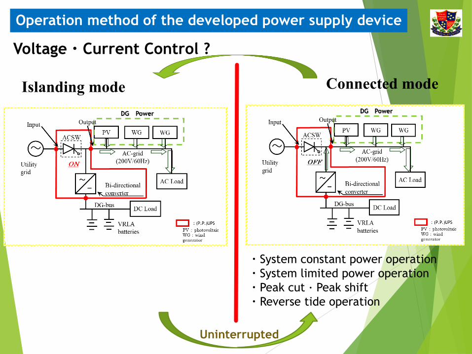
Operation method of the developed power supply device
Uninterrupted
Voltage・Current Control ?
Islanding mode Connected mode
・System constant power operation・System limited power operation・Peak cut · Peak shift・Reverse tide operation

Connected Mode
Power characteristics
Voltage characteristics
270
280
290
300
310
320
330
340
350
360
370
380
0:00 4:00 8:00 12:00 16:00 20:00 0:00
Volta
ge[V
]
Time[hh:mm]
Const. Power

Power exchange・It is possible to supply power to DC load with reduced loss. ・Energy loss of power exchange can be reduced by the battery and
distributed power connected to the DC system.・The capacity of the possible power exchange does not depend on the
system capacity.
10

Power exchange (system configuration)
The figure shows the system configuration when a PFC is used.Between MG 1 and MG 2, PFC is introduced.
11

Experimental results using PFC
Conditions of electric power exchange
Eg: MG1:340V MG2:330V MG1⇒MG2MG1:320V MG2:330V MG2⇒MG1
When PFC was used, it was judged only by the DC voltage value of the grid.When the voltage deviates from the set value, power is exchanged.
MG1 MG2
Vbatt_max 336 340
Vbatt_min 330 320
Set voltage of each MG
Name Capacity The number of system
Photovoltaic system 4kW 2
Bi-directional converter
20kVA 2
Storage battery 15.6kWh 2
Load 3kW
PFC 10kW 1
Specification
12

Charging/discharging characteristic storage battery
Island modePower interchange
mode
2096.8 1682.5
Decrease of 19.8%
Rechargeable battery charge[Wh]
In case of Island mode In case of Power exchange mode
Power characteristics (MG1)
13

Power characteristics (MG2) In case of Island mode In case of Power exchange mode
Charging/discharging characteristic storage battery
Island modePower interchange
mode
280.1 275.6
Decrease of 1.6%
Rechargeable battery charge[Wh]
14

DC MicroGrds in Aichi Institute of Technology
We conducted the experiments which used this micro grids

AC power supply system and DC power supply system in LED lighting
Rectifier
LED using AC LED using DC

1
照度計
Experiment environment

AC100V(Dimming rate85%)
AC1 DC2
Volatege [V] 100.2 180.0
Current [A] 0.346 0.169
Power [W] 34.0 30.2
Illuminance [lx] 1152
Efficiency [%] DC2[W]/AC1[W] 88.8
AC200V(Dimming rate85%)
AC1 DC2
Voltage [V] 200.3 180.0
Current [A] 0.172 0.169
Power [W] 33.5 30.2
Illuminance [lx] 1152
Efficiency [%] DC2[W]/AC1[W] 90.1
DC380V(Dimming rate 85%)
DC1 DC2
Voltage [V] 380.3 179.9
Current [A] 0.085 0.166
Power [W] 32.2 29.9
Illuminance [lx] 1140
Efficiency [%] DC2[W]/AC1[W] 92.9
LED lighting using AC / DC Power
DC-LEDはAC-LEDと比較して
2.8%(AC200V)
4.1%(AC100V)
効率が良い

The air conditioner equipment using DC power supply

Solar power panelPmax 70WVoc 20.4VIsc 4.87A
Vpm 15.8VIpm 4.43A
Power Conditioning systemRated power 5.5kW
Rated input voltage DC250VInput operation
voltage range DC0~400V
Rated output voltage AC202±12VRated frequency 50/60Hz
Power factor 0.95
Maximum output power 1.3kWInput operation voltage range DC40~230V
Voltage boost range magnification 1.1~4
Number of circuit 1Power conversion efficiency 98%
Indoor unitRated voltage 100V
Rated frequency 50/60HzRated power consumption of
the electric motor 0.77kWCooling operation current 6.5A
Rated cooling power consumption 0.56kW
Outdoor unitRated voltage 100V
Rated frequency 50/60HzCompressor electrical motor
output 600W
Air Conditioner
DC/DC Converter unit
Specifications
The specifications of each unit used in the aforementioned test system are presented in these tables.

Mode II (with PCS)
Mode III (with PCS )
Mode I(DC power supply)
This system has three operation modes.

Mode I (DC power supply)
This system is a mode which consumes all the outputs of PV by an air-conditioner. When the output of PV is not enough, the power from a grid is used for an air conditioner. When the outputs of PV is enough,we cannot use a power for other equipment.
MPPT control
Experimental of mode I

23
Power consumption of the air conditioner>>> AC power supply >>> DC power supply
Photovoltaic Power
Generation
Air Conditioner
AC DCCompressor ~ACDCDC/DCConverter
DCDC
DC power supply mode
AC power supply mode Measurement point of the DC electric powerMeasurement point of the AC electric power
MODEAC
Power (kW)DC
Power (kW)PV
Out put (kW)Room
temperature(℃)Room
humidity(%)Outside
temperature(℃)Outside
humidity(%)
DC 0.01 2.22 2.46 22.4 16.2 5.2 47.3AC 2.35 0.03 0.15 22.3 17.9 5.0 56.1
Performance comparison of AC and DC

Performance comparison of AC and DC

Conclusion■We introduced the AC/DC hybrid-type grid of
Aichi Institute of Technology.
■We developed PFCs to for the experimental model, and the expected operation by certain control has been demonstrated.
■In this presentation, we reported on the demonstration of the basic operation.In the future, we will continue studies for quantification of protective coordination, power supply stabilities, higher efficiency, and cost benefits.

Thank you for your cooperation.