abrasivewaterjetcuttingsystems...
TRANSCRIPT

ABRASIVE WATER JET CUTTING SYSTEMSFOR JACKETS & SUBSEASTRUCTURE REMOVALSProviding Total Solutions Through Cutting Technology
OIL STATES MCS LTDBOUTHWOOD ROADSOWERBY WOODS
BARROW-IN-FURNESSCUMBRIA LA14 4HBENGLAND, UK
Tel: +44 (0) 1229 825080Fax: +44 (0) 1229 839791
e-mail: [email protected]
www.oilstates.com

Printed October 2010, 4K
ICMl in Launch Frame ICM Deck Test Jacket Recovery Subsea Internal Cutting Tool
INTRINSICALLY SAFE - ENVIRONMENTALLY FRIENDLY - REMOTE-CONTROLLEDFAST - CLEAN - ECONOMICAL - EFFICIENT - REPEATABLE - DEPENDABLE
If you’re involved in offshore structure removals, then only one technology gives you all this in a powerful cuttingaction when used underwater, in air and below the mudline - Abrasive Water Jet cutting technology from Oil StatesMCS Ltd.
• PowerfulAbrasive particles are entrained into a high-energy water stream creating an abrasive slurry, which is pumpedthrough a single hose to a nozzle mounted within and positioned by a vast assortment of remotely operated tools.
• Cutting ToolsThe remote-controlled internal and external cutting tools manipulate the nozzle around the target materialproducing a clean, precise cut through single and multiple layers of material, including hardened alloys and wellstring conductors with both grouted and water-filled annuli.
• AssuranceThe entire cutting spread is supplied and operated by Oil States MCS Ltd. The equipment is thoroughly tested,commissioned and operated at all times in accordance with documented quality procedures and operation manuals.
• ReliabilityDevelopment of the Oil States MCS abrasive water jet cutting system has been continual. Through innovativedesign, robust testing and meticulous operation, all equipment is consistently reliable and efficient. This isoptimised by the use of interchangeable component parts where possible throughout the tools.
• QualityThe Oil States MCS Quality Management System operates in compliance with ISO 9001: 2008, Certificate No.001393. All the cutting equipment is assembled and tested in accordance with Oil States MCS quality proceduremanuals and records maintained accordingly.
• ExperienceOil States MCS has been developing and operating their Abrasive Water Jet cutting equipment since the mid 1980s.We have been at the forefront of the development of reliable, efficient and safe remote cutting systems, primarilyin subsea applications and offer this expertise to you.
90mm Pile Cut Casing Assembly Cut ICM Sub Mudline Pile Cut ROV Tool in basket

Features
• Intrinsically safe• Remotely controlled• Economical• Efficient• Environmentally friendly• Powerful• Repeatable• Dependable
Abrasive Water JetCutting Technology
Oil States MCS have been an Abrasive Water Jet cutting service provider to the oil and gas industry since the 1980s. Our cuttingsystems, which are primarily used during the decommissioning and removal of redundant offshore platforms, pipelines and subseastructures, are also used during platform maintenance and upgrade programs.
The incisive penetrating cutting action of the Abrasive Water Jet system makes it suitable for both surface and subseaapplications. A high-energy jet of water-borne abrasive particles is used to cut through steel alloys or multiple layers of material.This is achieved by entraining abrasive into the high-pressure water stream at the surface and pumping the pressurised slurrymixture through a single hose to the cutting nozzle to produce a clean, accurate cut with a good surface finish.
All our Abrasive Water Jet cutting equipment and tooling is designed, built and operated by Oil States MCS personnel. Wecontinually develop and improve our cutting equipment from experience gained in the field. All operations undertaken are fullydocumented and in accordance with ISO 9001:2008 Quality Assurance and ISO 14001 environmental accreditation systems.
Our design team use the latest 3D design and computerised stress analysis software to provide optimum tooling solutions tomeet project requirements. We have supplied subsea cutting solutions during numerous critical decommissioning operations andprovide internal, external, standard and bespoke cutting tools to suit all applications. Real-time cut monitoring and positioningfeatures are integrated into the tooling packages enabling cutting in the harshest of subsea, sub-mudline environments, oftenwhere there is zero visibility. Through the use of carefully planned and adjustable operational parameters each cut is assured,in every situation, with complete confidence.
Introduction
PAGE 1
External cut in progress monitored using cutting tool camera
Jacket removal using a single lift sub-mudline pile cutting
Jacket removal in sectionsJacket top section: midwater cuts on the leg/pile assemblies and diagonal bracesJacket footing: sub-mudline pile cuts
A clean, accurate sub-mudline pile cut completed using Oil States MCS Abrasive Water Jet Cutting system
Abrasive Mixer Unit
Features
• Standard operating control layout• Overpressurisation safety systems• Working pressure 1,000 bar +• Project-specific certification and calibration• Dual vessels provide near-continuous cutting• Real-time adjustable operating parameters
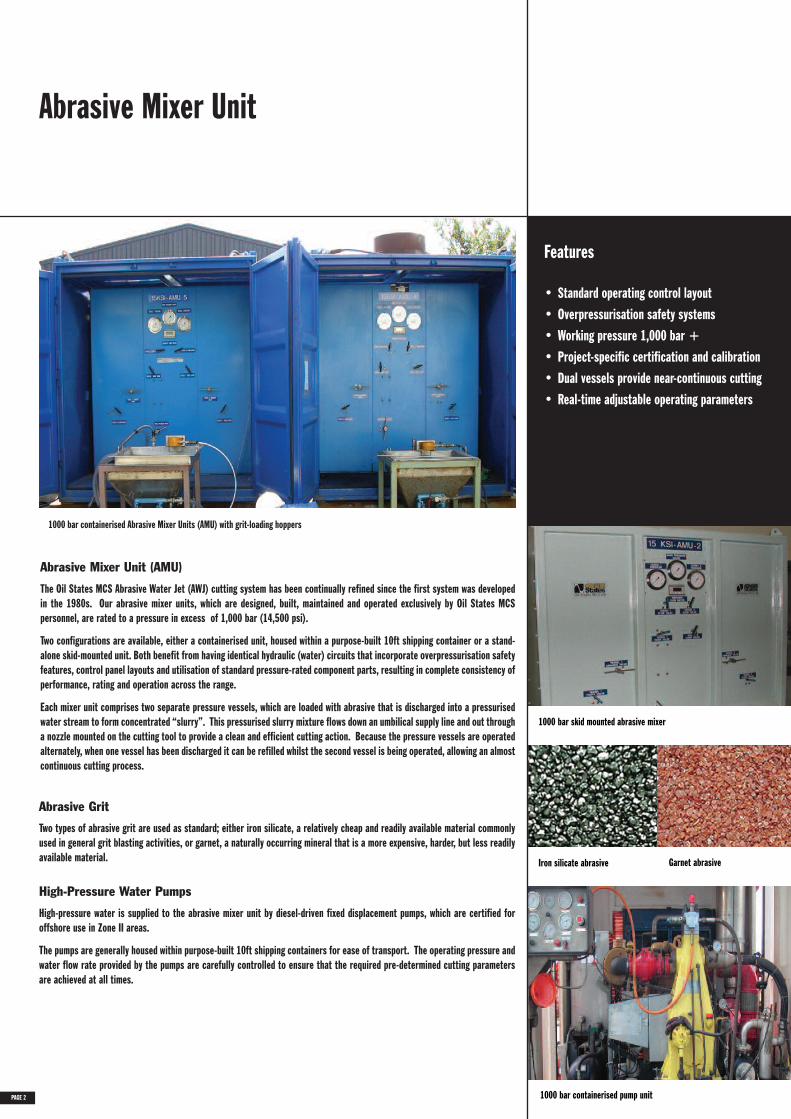
The Oil States MCS Abrasive Water Jet (AWJ) cutting system has been continually refined since the first system was developedin the 1980s. Our abrasive mixer units, which are designed, built, maintained and operated exclusively by Oil States MCSpersonnel, are rated to a pressure in excess of 1,000 bar (14,500 psi).
Two configurations are available, either a containerised unit, housed within a purpose-built 10ft shipping container or a stand-alone skid-mounted unit. Both benefit from having identical hydraulic (water) circuits that incorporate overpressurisation safetyfeatures, control panel layouts and utilisation of standard pressure-rated component parts, resulting in complete consistency ofperformance, rating and operation across the range.
Each mixer unit comprises two separate pressure vessels, which are loaded with abrasive that is discharged into a pressurisedwater stream to form concentrated “slurry”. This pressurised slurry mixture flows down an umbilical supply line and out througha nozzle mounted on the cutting tool to provide a clean and efficient cutting action. Because the pressure vessels are operatedalternately, when one vessel has been discharged it can be refilled whilst the second vessel is being operated, allowing an almostcontinuous cutting process.
Abrasive Mixer Unit (AMU)
Abrasive Grit
Two types of abrasive grit are used as standard; either iron silicate, a relatively cheap and readily available material commonlyused in general grit blasting activities, or garnet, a naturally occurring mineral that is a more expensive, harder, but less readilyavailable material.
High-pressure water is supplied to the abrasive mixer unit by diesel-driven fixed displacement pumps, which are certified foroffshore use in Zone II areas.
The pumps are generally housed within purpose-built 10ft shipping containers for ease of transport. The operating pressure andwater flow rate provided by the pumps are carefully controlled to ensure that the required pre-determined cutting parametersare achieved at all times.
High-Pressure Water Pumps
PAGE 2
1000 bar containerised Abrasive Mixer Units (AMU) with grit-loading hoppers
1000 bar containerised pump unit
Iron silicate abrasive Garnet abrasive
1000 bar skid mounted abrasive mixer
Internal Cutting Manipulator (ICM)
ICM Features
• Fully remote controlled• Operable in zero visibility• Robust design• Interchangeable sub-assemblies and
component parts• Real-time nozzle tracking system• Real-time adjustable nozzle travel speed• Fail-safe tool recovery design• Subsea cuts performed in 300 metre water
depth
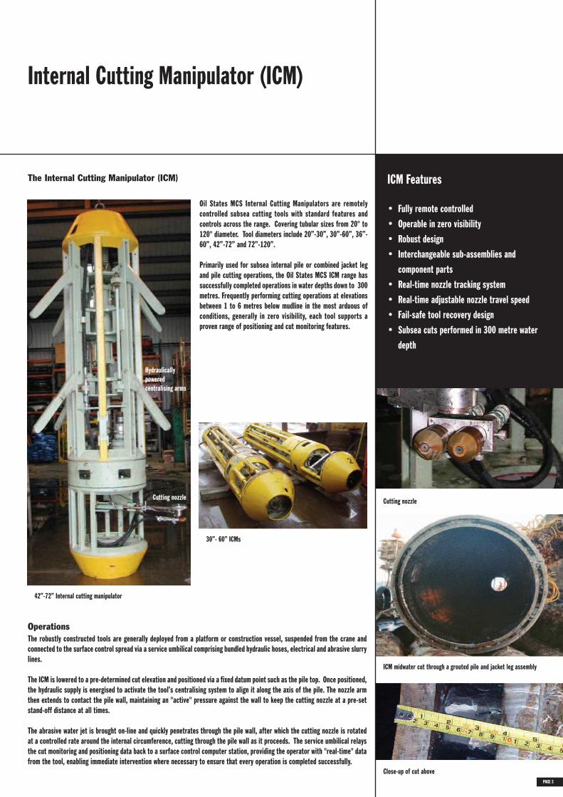
Oil States MCS Internal Cutting Manipulators are remotelycontrolled subsea cutting tools with standard features andcontrols across the range. Covering tubular sizes from 20" to120" diameter. Tool diameters include 20”-30”, 30”-60”, 36”-60”, 42”-72” and 72”-120”.
Primarily used for subsea internal pile or combined jacket legand pile cutting operations, the Oil States MCS ICM range hassuccessfully completed operations in water depths down to 300metres. Frequently performing cutting operations at elevationsbetween 1 to 6 metres below mudline in the most arduous ofconditions, generally in zero visibility, each tool supports aproven range of positioning and cut monitoring features.
The Internal Cutting Manipulator (ICM)
The robustly constructed tools are generally deployed from a platform or construction vessel, suspended from the crane andconnected to the surface control spread via a service umbilical comprising bundled hydraulic hoses, electrical and abrasive slurrylines.
The ICM is lowered to a pre-determined cut elevation and positioned via a fixed datum point such as the pile top. Once positioned,the hydraulic supply is energised to activate the tool’s centralising system to align it along the axis of the pile. The nozzle armthen extends to contact the pile wall, maintaining an "active" pressure against the wall to keep the cutting nozzle at a pre-setstand-off distance at all times.
The abrasive water jet is brought on-line and quickly penetrates through the pile wall, after which the cutting nozzle is rotatedat a controlled rate around the internal circumference, cutting through the pile wall as it proceeds. The service umbilical relaysthe cut monitoring and positioning data back to a surface control computer station, providing the operator with "real-time" datafrom the tool, enabling immediate intervention where necessary to ensure that every operation is completed successfully.
Operations
Hydraulicallypoweredcentralising arms
Cutting nozzle
Close-up of cut above
ICM midwater cut through a grouted pile and jacket leg assembly
PAGE 3
42”-72” Internal cutting manipulator
Cutting nozzle
30”- 60” ICMs

Internal Cutting Manipulator (ICM)Deployment Methods
The direct deployment method can be used for either subsea or surface cutting tool deployment applications. With this method,the tool is suspended from the vessel crane via a positioning frame and sling. Stabbed directly into the pile/jacket leg, thecutting tool is lowered until the positioning frame lands on the pile/jacket leg top. A fixed length sling fitted between thepositioning frame and cutting tool ensures that the tool is located correctly at the required cutting elevation. A simpleadjustment mechanism allows the positioning frame to be altered to account for variations in pile/jacket leg top elevation,ensuring that all severances are made at the same elevation. The crane deployment rigging is either slackened off to removevessel motion or disconnected prior to performing cutting operations.
Operational Advantages
• Direct Deployment• Simple cut depth adjustment• Rapid deployment
• Launch Frame Unit• 30" - 72" diameter• Releases vessel crane for other operations• Multiple cuts at varying elevations
• Cut and Recovery• 42" - 72" diameter• Pile stick-up removal in one operation• Fail-safe tool operation
Direct Deployment Method
Oil States MCS Internal Cutting Manipulators can be deployed using two handling options, either the direct deployment methodor the Launch Frame deployment method.
Pile Stick-up RemovalAs a variant of the direct deployment method, Oil States MCS offer a system for cutting and recovering pile stick-up sections ina single tool deployment. With this arrangement, the positioning frame incorporates purpose-built hydraulically actuated fail-safe clamping units, which can be adjusted to handle pile sections ranging from 42” to 72” in diameter up to 20te in weight.
Launch Frame Deployment Method
With the launch frame deployment method, the cutting tool isdeployed from a purpose-built frame, which is stabbed into thejacket leg pile, releasing the vessel crane for other activities.The Launch Frame houses the cutting tool and incorporates twowinch units: one to lower and recover the cutting tool, the otherfor running the tool’s service umbilical. The cutting tool ispositioned using elevation markings on the tool lift wire setagainst a fixed indicator on the launch frame. A tool-mountedpressure transducer confirms the tool’s elevation within thepile. This deployment method is ideal for performing multiplecuts on main leg piles during a single tool deployment, i.e. asub-mudline cut followed by a midwater cut on the same pilewhen removing larger jackets in sections.
ICM direct deployment - skirt pile cuts
PAGE 442” to 72” ICM pile cutting and recovery tool configurations
ICM-LFU deployment ICM direct crane deployment
LFU deployed on tripod jacket
Platform and Subsea WellCutting Operations
Multiple well removals campaign, cuts on 13-3/8”, 20” & 30” voided well casing assemblies
Features
• Real-time nozzle tracking system• Remotely adjustable nozzle travel speed• Multi-string cutting both cemented and voided
annuli• Tool sized to run in standard casing sizes• Tool sizes available 9-5/8”, 13-3/8” and
20”
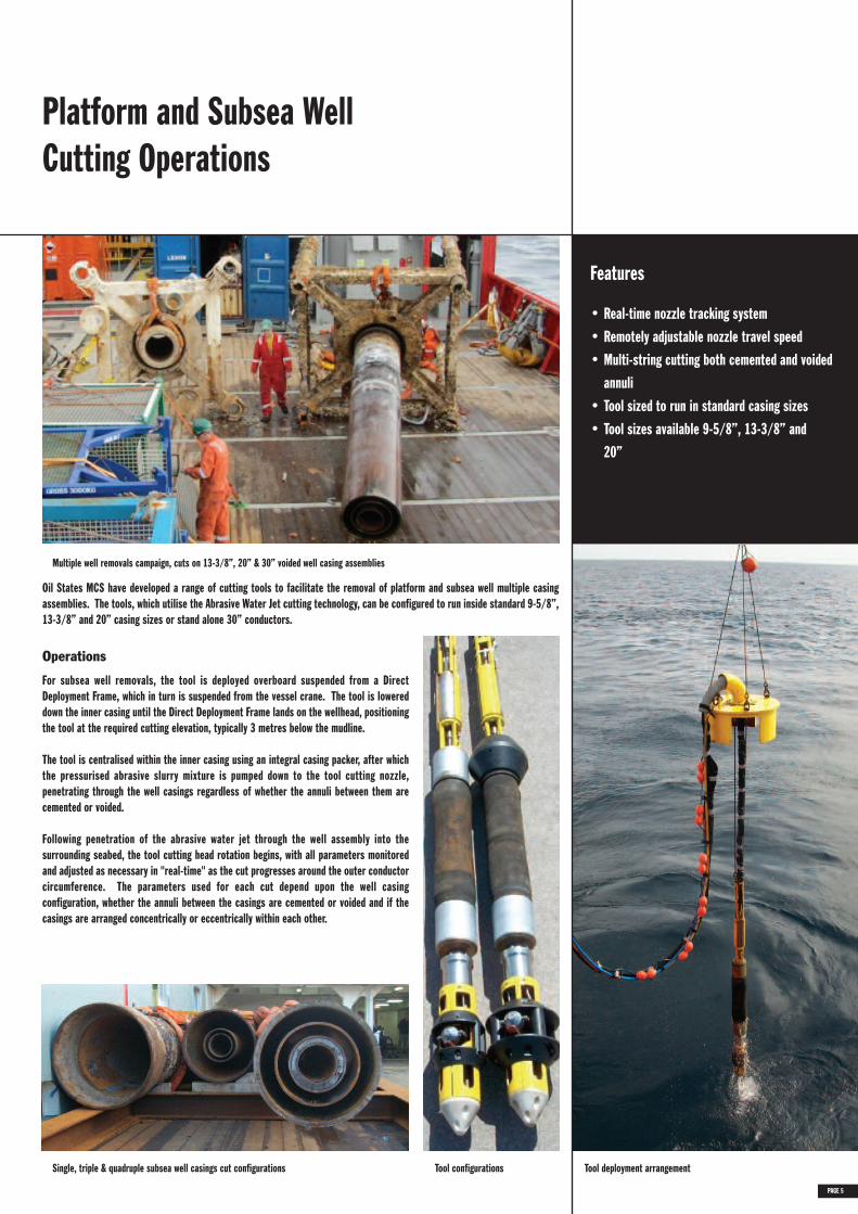
Oil States MCS have developed a range of cutting tools to facilitate the removal of platform and subsea well multiple casingassemblies. The tools, which utilise the Abrasive Water Jet cutting technology, can be configured to run inside standard 9-5/8”,13-3/8” and 20” casing sizes or stand alone 30” conductors.
Single, triple & quadruple subsea well casings cut configurations Tool deployment arrangement
Operations
For subsea well removals, the tool is deployed overboard suspended from a DirectDeployment Frame, which in turn is suspended from the vessel crane. The tool is lowereddown the inner casing until the Direct Deployment Frame lands on the wellhead, positioningthe tool at the required cutting elevation, typically 3 metres below the mudline.
The tool is centralised within the inner casing using an integral casing packer, after whichthe pressurised abrasive slurry mixture is pumped down to the tool cutting nozzle,penetrating through the well casings regardless of whether the annuli between them arecemented or voided.
Following penetration of the abrasive water jet through the well assembly into thesurrounding seabed, the tool cutting head rotation begins, with all parameters monitoredand adjusted as necessary in "real-time" as the cut progresses around the outer conductorcircumference. The parameters used for each cut depend upon the well casingconfiguration, whether the annuli between the casings are cemented or voided and if thecasings are arranged concentrically or eccentrically within each other.
PAGE 5
Tool configurations
Bespoke Subsea CuttingTools
Tooling Solutions Available For Cutting
• Intake holes in firewater or seawatercaissons
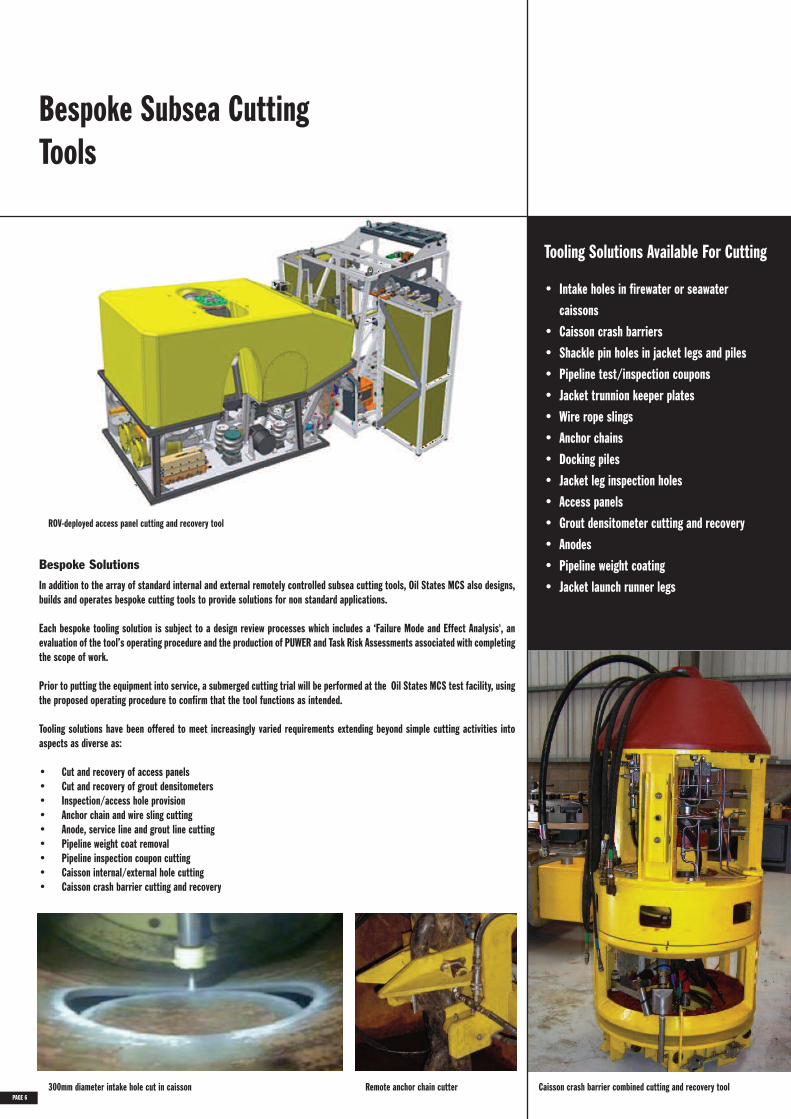
• Caisson crash barriers• Shackle pin holes in jacket legs and piles• Pipeline test/inspection coupons• Jacket trunnion keeper plates• Wire rope slings• Anchor chains• Docking piles• Jacket leg inspection holes• Access panels• Grout densitometer cutting and recovery• Anodes• Pipeline weight coating• Jacket launch runner legsIn addition to the array of standard internal and external remotely controlled subsea cutting tools, Oil States MCS also designs,
builds and operates bespoke cutting tools to provide solutions for non standard applications.
Each bespoke tooling solution is subject to a design review processes which includes a ‘Failure Mode and Effect Analysis', anevaluation of the tool’s operating procedure and the production of PUWER and Task Risk Assessments associated with completingthe scope of work.
Prior to putting the equipment into service, a submerged cutting trial will be performed at the Oil States MCS test facility, usingthe proposed operating procedure to confirm that the tool functions as intended.
Tooling solutions have been offered to meet increasingly varied requirements extending beyond simple cutting activities intoaspects as diverse as:
• Cut and recovery of access panels• Cut and recovery of grout densitometers• Inspection/access hole provision• Anchor chain and wire sling cutting• Anode, service line and grout line cutting• Pipeline weight coat removal• Pipeline inspection coupon cutting• Caisson internal/external hole cutting• Caisson crash barrier cutting and recovery
Bespoke Solutions
300mm diameter intake hole cut in caisson Remote anchor chain cutter
ROV-deployed access panel cutting and recovery tool
PAGE 6Caisson crash barrier combined cutting and recovery tool
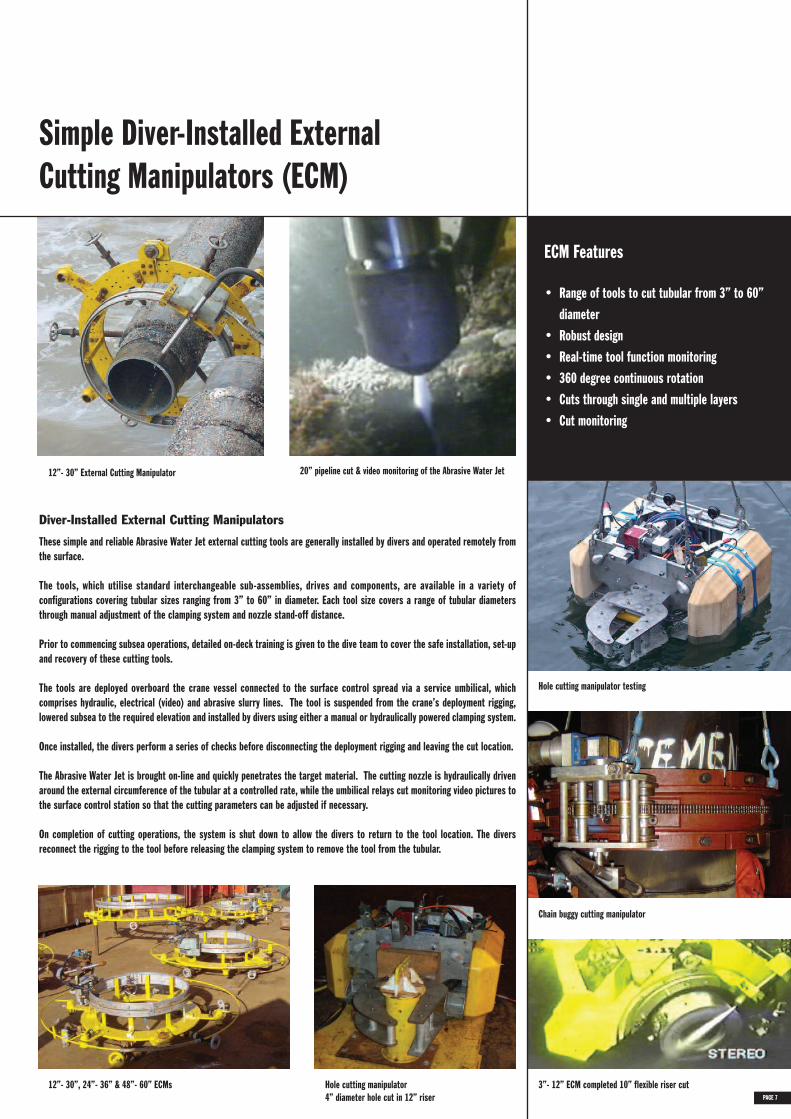
Simple Diver-Installed ExternalCutting Manipulators (ECM)
ECM Features
• Range of tools to cut tubular from 3” to 60”diameter
• Robust design• Real-time tool function monitoring• 360 degree continuous rotation• Cuts through single and multiple layers• Cut monitoring
Chain buggy cutting manipulator
These simple and reliable Abrasive Water Jet external cutting tools are generally installed by divers and operated remotely fromthe surface.
The tools, which utilise standard interchangeable sub-assemblies, drives and components, are available in a variety ofconfigurations covering tubular sizes ranging from 3” to 60” in diameter. Each tool size covers a range of tubular diametersthrough manual adjustment of the clamping system and nozzle stand-off distance.
Prior to commencing subsea operations, detailed on-deck training is given to the dive team to cover the safe installation, set-upand recovery of these cutting tools.
The tools are deployed overboard the crane vessel connected to the surface control spread via a service umbilical, whichcomprises hydraulic, electrical (video) and abrasive slurry lines. The tool is suspended from the crane’s deployment rigging,lowered subsea to the required elevation and installed by divers using either a manual or hydraulically powered clamping system.
Once installed, the divers perform a series of checks before disconnecting the deployment rigging and leaving the cut location.
The Abrasive Water Jet is brought on-line and quickly penetrates the target material. The cutting nozzle is hydraulically drivenaround the external circumference of the tubular at a controlled rate, while the umbilical relays cut monitoring video pictures tothe surface control station so that the cutting parameters can be adjusted if necessary.
On completion of cutting operations, the system is shut down to allow the divers to return to the tool location. The diversreconnect the rigging to the tool before releasing the clamping system to remove the tool from the tubular.
Diver-Installed External Cutting Manipulators
12”- 30” External Cutting Manipulator 20” pipeline cut & video monitoring of the Abrasive Water Jet
12”- 30”, 24”- 36” & 48”- 60” ECMs Hole cutting manipulator4” diameter hole cut in 12” riser PAGE 7
Hole cutting manipulator testing
3”- 12” ECM completed 10” flexible riser cut

ROV-Deployed ExternalCutting Manipulators (ECM)
PAGE 8
ROV-Deployed ECM Features
• Range of tools to cut tubular from 3” to 60”diameter
• Uses ROV valve chest technology• Real-time tool function monitoring• Tool clamping using surface or ROV hydraulics• 360 degree continuous rotation• Vertical nozzle travel• Remotely adjustable from surface• Castellated cuts• Cuts through single and multiple layers• Cut monitoring
Covering tubular sizes ranging from 3" to 60" diameter, our ROV-deployed external cutting manipulators utilise the very latestremote control technology. The tools incorporate a selection of options, which provide for very simple square cuts, angled cutsand more complex castellated (stepped) cut profiles depending on specific project requirements. The robust manipulatorsfeature state of the art software-controlled functions, which are operated and monitored in "real-time" at the surface through alaptop computer.
The tools, which are connected to the surface control equipment via a service umbilical, can be deployed subsea either suspendedfrom a vessel crane or alternatively in a tool basket for collection and installation by a Work Class ROV fitted with an Oil StatesMCS Rotary Docking Module (RDM).
The RDM, which is secured to the ROV chassis and powered via its hydraulic power pack, provides the interface between theexternal cutting tool and Work Class ROV. It allows the ROV to dock with the cutting tool, release its clamping system andtransfer the tool from the deployment basket to the required cut location. The RDM incorporates both a pitch and roll function,which allows the ROV pilot to align the cutting tool with the work piece before clamping it in position.
Once installed, the ROV undocks from the tool, leaving it to perform its remote cutting operation.
12”- 24” External Cutting ManipulatorFour castellated cuts made around the circumference of a 24” tubular
ROV-Deployed External Cutting Manipulator
24”- 36” ECM in subsea tool deployment basket
Rotary docking module mounted to ROV
Cutting tool handling trials with ROV
Anode cutting manipulator 3”- 6” cutting manipulator

Printed October 2010, 4K
ICMl in Launch Frame ICM Deck Test Jacket Recovery Subsea Internal Cutting Tool
INTRINSICALLY SAFE - ENVIRONMENTALLY FRIENDLY - REMOTE-CONTROLLEDFAST - CLEAN - ECONOMICAL - EFFICIENT - REPEATABLE - DEPENDABLE
If you’re involved in offshore structure removals, then only one technology gives you all this in a powerful cuttingaction when used underwater, in air and below the mudline - Abrasive Water Jet cutting technology from Oil StatesMCS Ltd.
• PowerfulAbrasive particles are entrained into a high-energy water stream creating an abrasive slurry, which is pumpedthrough a single hose to a nozzle mounted within and positioned by a vast assortment of remotely operated tools.
• Cutting ToolsThe remote-controlled internal and external cutting tools manipulate the nozzle around the target materialproducing a clean, precise cut through single and multiple layers of material, including hardened alloys and wellstring conductors with both grouted and water-filled annuli.
• AssuranceThe entire cutting spread is supplied and operated by Oil States MCS Ltd. The equipment is thoroughly tested,commissioned and operated at all times in accordance with documented quality procedures and operation manuals.
• ReliabilityDevelopment of the Oil States MCS abrasive water jet cutting system has been continual. Through innovativedesign, robust testing and meticulous operation, all equipment is consistently reliable and efficient. This isoptimised by the use of interchangeable component parts where possible throughout the tools.
• QualityThe Oil States MCS Quality Management System operates in compliance with ISO 9001: 2008, Certificate No.001393. All the cutting equipment is assembled and tested in accordance with Oil States MCS quality proceduremanuals and records maintained accordingly.
• ExperienceOil States MCS has been developing and operating their Abrasive Water Jet cutting equipment since the mid 1980s.We have been at the forefront of the development of reliable, efficient and safe remote cutting systems, primarilyin subsea applications and offer this expertise to you.
90mm Pile Cut Casing Assembly Cut ICM Sub Mudline Pile Cut ROV Tool in basket

ABRASIVE WATER JET CUTTING SYSTEMSFOR JACKETS & SUBSEASTRUCTURE REMOVALSProviding Total Solutions Through Cutting Technology
OIL STATES MCS LTDBOUTHWOOD ROADSOWERBY WOODS
BARROW-IN-FURNESSCUMBRIA LA14 4HBENGLAND, UK
Tel: +44 (0) 1229 825080Fax: +44 (0) 1229 839791
e-mail: [email protected]
www.oilstates.com