about the author - springer978-3-540-33704-1/1 · of nuclear power plants, ... htgr...
TRANSCRIPT
About the Author
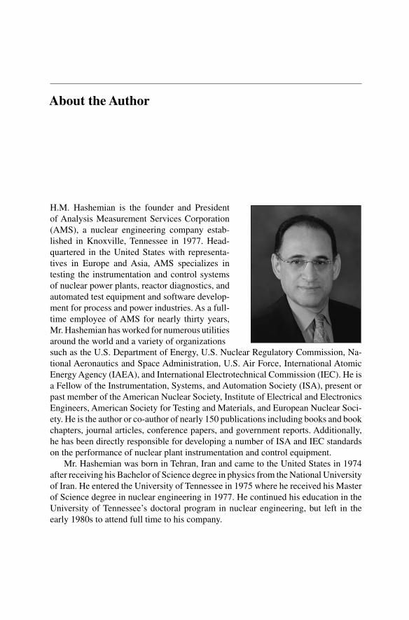
H.M. Hashemian is the founder and Presidentof Analysis Measurement Services Corporation(AMS), a nuclear engineering company estab-lished in Knoxville, Tennessee in 1977. Head-quartered in the United States with representa-tives in Europe and Asia, AMS specializes intesting the instrumentation and control systemsof nuclear power plants, reactor diagnostics, andautomated test equipment and software develop-ment for process and power industries. As a full-time employee of AMS for nearly thirty years,Mr. Hashemian has worked for numerous utilitiesaround the world and a variety of organizationssuch as the U.S. Department of Energy, U.S. Nuclear Regulatory Commission, Na-tional Aeronautics and Space Administration, U.S. Air Force, International AtomicEnergy Agency (IAEA), and International Electrotechnical Commission (IEC). He isa Fellow of the Instrumentation, Systems, and Automation Society (ISA), present orpast member of the American Nuclear Society, Institute of Electrical and ElectronicsEngineers, American Society for Testing and Materials, and European Nuclear Soci-ety. He is the author or co-author of nearly 150 publications including books and bookchapters, journal articles, conference papers, and government reports. Additionally,he has been directly responsible for developing a number of ISA and IEC standardson the performance of nuclear plant instrumentation and control equipment.
Mr. Hashemian was born in Tehran, Iran and came to the United States in 1974after receiving his Bachelor of Science degree in physics from the National Universityof Iran. He entered the University of Tennessee in 1975 where he received his Masterof Science degree in nuclear engineering in 1977. He continued his education in theUniversity of Tennessee’s doctoral program in nuclear engineering, but left in theearly 1980s to attend full time to his company.

Acknowledgement
The effort of all technical and administrative staff of Analysis and MeasurementServices Corporation who helped with the production of this book is gratefully ac-knowledged. In particular, Ms. Elain Crumley is appreciated for her role in managingthe administrative aspects of this book and working with the publisher, Mr. DarrellMitchell is recognized for directing the production of the figures, drawings, pho-tographs and coordinating the effort of technical staff who helped the author. Also,Mr. Paul Bodine, an independent technical book editor, is acknowledged for his rolein proofreading and editing this book.
Acronyms and Abbreviations
AMS Analysis and Measurement Services CorporationANO Arkansas Nuclear OneANSI American National Standards InstituteAPD amplitude probability densityAR autoregressive (refers to autoregressive modeling)ASTM American Society for Testing and Materials
B&W Babcock and WilcoxBTP-13 Branch Technical Position 13BWR Boiling Water Reactor
C capacitanceCANDU Canadian deuterium reactor (Canadian heavy water reactor)CEA Commissariat à l’Energie AtomiqueCF correction factorCFR Code of Federal RegulationsCRBR Clinch River Breeder ReactorCRDM control rod drive mechanism
DBE design basis eventDOD U.S. Department of DefenseDOE U.S. Department of EnergyDPU differential pressure unit
EdF Electricité de FranceEMF electromotive forceEMI/RFI electromagnetic/radio frequency interferenceEPRI Electric Power Research Institute

242 Acronyms and Abbreviations
FFT fast Fourier transform
HELB high-energy line breakHFIR high flux isotope reactorHRP Halden Reactor ProjectHTGR high-temperature gas-cooled reactorI&C instrumentation and controlIAEA International Atomic Energy AgencyIEC International Electrotechnical CommissionIEEE Institute of Electrical and Electronics EngineersINPO Institute of Nuclear Power OperationsIR insulation resistanceISA Instrumentation, Systems, and Automation Society (formerly Instrument
Society of America)
L inductanceLCR inductance, capacitance, and resistanceLCSR loop current step response (refers to the method for in-situ response time
testing of RTDs and thermocouples)LER licensee event reportLMFBR liquid metal fast breeder reactorLOCA loss-of-coolant accidentLPRM local power range monitor
mA MilliamperemW Milliwatt
NASA National Aeronautics and Space AdministrationNBS National Bureau of Standards (now National Institute of Standards and
Technology – NIST)NI neutron instrumentationNII Nuclear Installation Inspectorate (UK)NIST National Institute of Standards and Technology (formerly the National Bu-
reau of Standards – NBS)NMAC Nuclear Maintenance Assistance CenterNPAR Nuclear Plant Aging Research ProgramNPRDS Nuclear Plant Reliability Data SystemNRC Nuclear Regulatory Commission (U.S.)NRR Office of Nuclear Regulatory RegulationNTIS National Technical Information Service
ORNL Oak Ridge National Laboratory

Acronyms and Abbreviations 243
PRT platinum resistance thermometerPSD power spectral densityPWR pressurized water reactor
QA quality assuranceR resistanceR&D research and developmentRCP reactor coolant pumpRES NRC Office of ResearchRMS root mean squareRSS root sum squaredRTD resistance temperature detector
SBIR Small Business Innovation ResearchSER safety evaluation reportSG steam generatorSHI self-heating indexSPRT standard platinum resistance thermometers
TDR time domain reflectometryTECDOC IAEA technical reportTMI Three Mile Island (refers to Three Mile Island nuclear power plant)TVA Tennessee Valley Authority
UT University of Tennessee in Knoxville
VVER Russian PWR

References
1. Hashemian, H.M. (2005) Sensor Performance and Reliability. ISA - Instrumentation, Sys-tems, and Automation Society, Research Triangle Park, North Carolina.
2. Analysis and Measurement Services Corporation (1979) Response Time Qualification ofResistance Thermometers in Nuclear Power Plant Safety System. Topical Report submittedto the NRC under Millstone 2 Docket No. 50–336, AMS, Knoxville, Tennessee.
3. Electric Power Research Institute (2000) On-line Monitoring of Instrument Channel Per-formance. EPRI Topical Report No TR-104965-RI, NRC SER, Palo Alto, California.
4. Electric Power Research Institute (1997) Rod Control System Maintenance Guide forWest-inghouse Pressurized Water Reactors. Nuclear Maintenance Application Center (NMAC)Report No TR-108152, Palo Alto, California.
5. U.S. Nuclear Regulatory Commission (1998) Advanced Instrumentation and MaintenanceTechnologies for Nuclear Power Plants. NUREG/CR-5501, Washington, DC.
6. Tew, WL, SW, Benz, SP, Dresselhaus, P, and Hashemian, HM (2005) NewTechnologies for Noise Thermometry with Applications in Harsh and-or RemoteOperating Environments. 51st International Instrumentation Symposium of Instrumen-tation, Systems and Automation Society (ISA), Knoxville, Tennessee.
7. U.S. Nuclear Regulatory Commission (1990) Aging of Nuclear Plant Resistance Temper-ature Detectors. NUREG/CR-5560, Washington, DC.
8. U.S. Nuclear Regulatory Commission (1995) On-Line Testing of Calibration of ProcessInstrumentation Channels in Nuclear Power Plants. NUREG/CR-6343, Washington, DC.
9. Hashemian, HM (2003) Instrument Calibration. Instrument Engineers’ Handbook, FourthEdition, Chapter 1.8, Process Measurement and Analysis, Volume 1, CRC Press.
10. U.S. Nuclear Regulatory Commission (1997) Standard Review Plan for the Review ofSafety Analysis Reports for Nuclear Power Plants. NUREG-0800, Washington, DC.
11. U.S. Nuclear Regulatory Commission (1981) Safety Evaluation Report Review of Resis-tance Temperature Detector Time Response Characteristics. NUREG-0809, Washington,DC.
12. Electric Power Research Institute (1978) In-Situ Response Time Testing of Platinum Re-sistance Thermometers. EPRI Report No NP-834, Vol 1, Palo Alto, California.
13. Electric Power Research Institute (1980) Temperature Sensor Response and Characteri-zation. EPRI Report No NP-1486, Palo Alto, California.
14. Electric Power Research Institute (1977) In Situ Response Time Testing of Platinum Resis-tance Thermometers. EPRI Report Number NP-459, Project 503-3, Palo Alto, California.
15. Hashemian, HM (2003) Response Time and Drift Testing. Instrument Engineers’ Hand-book, Fourth Edition, Chapter 1.9, Process Measurement and Analysis, Vol 1, CRC Press.
16. Hashemian, HM (2002) Safety Instrumentation and Justification of Its Cost. InstrumentEngineers’ Handbook, Third Edition, Chapter 2.11, Process Software and Digital Net-works, CRC Press.
17. Hashemian, HM (2002) Optimized Maintenance and Management of Aging of CriticalEquipment in Nuclear Power Plants, Power Plant Surveillance and Diagnostics. Chapter3, Applied Research with Artificial Intelligence, Springer-Verlag, New York.
18. U.S. Nuclear Regulatory Commission (1993) Long Term Performance and Aging Char-acteristics of Nuclear Plant Pressure Transmitters. NUREG/CR-5851, Washington, DC.
19. U.S. Nuclear Regulatory Commission (1995) Assessment of Fiber Optic Pressure Sensors.NUREG/CR-6312, Washington, DC.
20. International Atomic Energy Agency (2000) Management of Ageing of I&C Equipmentin Nuclear Power Plants. IAEA Publication TECDOC-1147, Vienna, Austria.

Appendix ABibliography
Appendix A: Bibliography
This appendix contains a comprehensive listing of publications by the author and hiscolleagues at AMS and elsewhere on topics that are related directly or indirectly tothe material covered in this book. Most of the publications contained in this appendixare available from one or more of the following resources. Note that the attached listincludes patents awarded or pending to author and his colleagues.
U.S. National Technical Information Services (NTIS) www.ntis.govU.S. Government Printing Office www.gpo.govIEC www.iec.chIAEA www.iaea.orgNRC Public Document Room www.nrc.govAMS www.ams-corp.comISA www.isa.orgASTM www.astm.orgUnited States Patent and Trademark Office www.uspto.gov
Addresses for organizations just mentioned are:
• National Technical Information Service, 5285 Port Royal Road, Springfield, VA22161 USA
• U.S. Government Printing Office, 732 North Capitol St. NW, Washington, DC20401 USA
• IEC Central Office, 3, rue de Varembé, P.O. Box 131, CH - 1211 GENEVA 20,Switzerland
• International Atomic Energy Agency, P.O. Box 100, Wagramer Strasse 5, A-1400Vienna, Austria
• AMS, 9111 Cross Park Drive, Building A-100, Knoxville, TN 37923 USA• ISA, 67 Alexander Drive, PO Box 12277, Research Triangle Park, NC 27709
USA• ASTM International, 100 Barr Harbor Drive, PO Box C700, West Conshohocken,
PA, 19428-2959 USA• Office of Public Affairs, U.S. Patent and Trademark Office, P. O. Box 1450,
Alexandria, VA 22313-1450 USA
250 Appendix A
U.S. Government Publications
G1. Hashemian, H.M., Holbert, K.E., Kerlin, T.W., Upadhyaya, B.R., “A Low Power FourierTransform Processor." NASA Goddard Space Flight Center, Contract Number NAS5-28635 (July 1985).
G2. Hashemian, H.M., “Determination of Installed Thermocouple Response." U.S.Air Force,Arnold Engineering Development Center, Report Number AEDC-TR-86-46 (December1986).
G3. Hashemian, H.M., Holbert, K.E., Thie, J.A., Upadhyaya, B.R., Kerlin, T.W., Petersen,K.M., Beck, J.R., “Sensor Surveillance Using Noise Analysis." U.S. Department ofEnergy, Contract Number DE-AC05-86ER80405 (March 1987).
G4. Hashemian, H.M., et al., “Degradation of Nuclear Plant Temperature Sensors." U.S.Nuclear Regulatory Commission, Report Number NUREG/CR-4928 (June 1987).
G5. Hashemian, H.M., et al., “Effect of Aging on Response Time of Nuclear Plant PressureSensors." U.S. Nuclear Regulatory Commission, NUREG/CR-5383 (June 1989).
G6. Hashemian, H.M., et al., “Aging of Nuclear Plant Resistance Temperature Detectors."U.S. Nuclear Regulatory Commission, Report Number NUREG/CR-5560 (June 1990).
G7. Hashemian, H.M., “New Technology for Remote Testing of Response Time of InstalledThermocouples." United States Air Force, Arnold Engineering Development Center,Report Number AEDC-TR-91-26, Volume 1 - Background and General Details (January1992).
G8. Hashemian, H.M., and Mitchell, D.W., “New Technology for Remote Testing of Re-sponse Time of Installed Thermocouples." United States Air Force, Arnold EngineeringDevelopment Center, Report Number AEDC-TR-91-26, Volume 2 - Determination ofInstalled Thermocouple Response Research Data (January 1992).
G9. Hashemian, H.M., et al., “New Technology for Remote Testing of Response Time ofInstalled Thermocouples." United States Air Force, Arnold Engineering DevelopmentCenter, Report Number AEDC-TR-91-26, Volume 3 - Thermocouple Response TimeTest Instrumentation (January 1992).
G10. Hashemian, H.M., et al., “Validation of Smart Sensor Technologies for Instrument Cal-ibration Reduction in Nuclear Power Plants." U.S. Nuclear Regulatory Commission,NUREG/CR-5903 (January 1993).
G11. Hashemian, H.M., “Long Term Performance and Aging Characteristics of NuclearPlant Pressure Transmitters." U.S. Nuclear Regulatory Commission, NUREG/CR-5851(March 1993).
G12. Hashemian, H.M., et al., “Improved Temperature Measurement in Composite Materialfor Aerospace Applications." National Aeronautics and Space Administration, MarshallSpace Flight Center, Contract Number NAS8-39814, MSFC, AL (July 1993).
G13. Hashemian, H.M., et al., “Assessment of Fiber Optic Pressure Sensors." U.S. NuclearRegulatory Commission, NUREG/CR-6312 (April 1995).
G14. Hashemian, H.M., et al., “New Sensor for Measurement of Low Air Flow Velocity." U.S.Nuclear Regulatory Commission, NUREG/CR-6334 (August 1995).
G15. Hashemian, H.M., “On-Line Testing of Calibration of Process Instrumentation Channelsin Nuclear Power Plants." U.S. Nuclear Regulatory Commission, NUREG/CR-6343(November 1995).

Appendix A 251
G16. Hashemian, H.M., Shell, C.S., and C.N. Jones, “New Instrumentation Technologies forTesting the Bonding of Sensors to Solid Materials." National Aeronautics and SpaceAdministration, Marshall Space Flight Center, NASA/CR-4744 (May 1996).
G17. Hashemian, H.M., et al., “Advanced Instrumentation and Maintenance Technologiesfor Nuclear Power Plants." U.S. Nuclear Regulatory Commission, NUREG/CR-5501(August 1998).
Journal Articles
J1. Kerlin, T.W., Miller, L.F., and Hashemian, H.M., “In-Situ Response Time Testing ofPlatinum Resistance Thermometers." ISA Transactions, Volume 17, No. 4, page 71-88(1978).
J2. Kerlin, T.W., Hashemian, H.M., and Petersen, K.M., “Time Response Testing of Temper-ature Sensors." ISA Transactions, Volume 20, No. 1 (1981).
J3. Hashemian, H.M., Thie, J.A., and Upadhyaya, B.R., “Reactor Sensor Surveillance Us-ing Noise Analysis." Nuclear Science and Engineering, Vol. 98, Number 2, pp. 96-102(February 1988).
J4. Hashemian, H.M., et al., “In Situ Response Time Testing of Thermocouples." ISA Trans-actions, Volume 29, Number 4, pp. 97-104 (1990).
J5. Hashemian, H.M., and Petersen, K.M., “Measurement of Performance of Installed Ther-mocouples." ISA Test Measurement Division Newsletter, Volume 29, Number 2 (April1992).
J6. Hashemian, H.M., “Effects of Normal Aging on Calibration and Response Time of Nu-clear Plant Resistance Temperature Detectors and Pressure Sensors." Nuclear SafetyTechnical Progress Journal, Volume 35, Number 2, pp. 223-234 (1994).
Magazine Articles
M1. Hashemian, H.M., and Petersen, K.M., “Boosting Accuracy of Industrial TemperatureMeasurement." Power Magazine, Vol. 133, No. 3, pp. 74-76 (May 1989).
M2. Hashemian, H.M., and Petersen, K.M., “AssuringAccurate Temperature Measurement."Intech Magazine, Vol. 36, No. 10, pp. 45-48 (October 1989).
M3. Hashemian, H.M., et al., “Measuring Critical Process Temperatures." Control Magazine,Vol. III, No. 4, pp. 62-69 (April 1990).
M4. Riner, J.L., “In-Situ Testing of Industrial Sensors." Control Magazine, Vol. 38, Number15, pp. 175-176 (November 1991).
M5. Petersen, K.M., “Testing Sensors ForAccuracy and Speed." Chemical Engineering Mag-azine, pp. 131-134 (February 1992).
M6. Hashemian, H.M., Petersen, K.M., “In-Situ Tests Gauge Thermocouple Performance,Part 1." Intech, Vol. 40, No. 1, pp. 30-32 (January 1993).
M7. Hashemian, H.M., Petersen, K.M., “In-Situ Tests Gauge Thermocouple Performance,Part 2." Intech, Vol. 40, No. 6, pp. 31-33 (June 1993).
M8. Hashemian, H.M., “Performance Testing of Nuclear Plant Temperature and PressureSensors." Nuclear Plant Journal, Vol. 12, No. 7, pp. 46 (November-December 1994).
M9. Hashemian, H.M., Riner, J.L., K.M. Petersen, D.D. Beverly, “Online Testing AssuresIntegrity of Sensors." Chemical Engineering, Vol. 102, No. 3, pp. 84-88 (March 1995).
252 Appendix A
M10. Hashemian, H.M., “Catching the Drift.” Pressure, a supplement to InTech Magazine, anISA publication (August 2003).
M11. ISA Editor (for H.M. Hashemian’s book), “Impulse Lines are Vital Intelligence Link.”Intech Magazine, an ISA publication (November 2005).
Technical Reports
T1. Hashemian, H.M., Jacquot, J.P., and Guerin, B., “Preliminary Report: Response TimeTesting of Resistance Temperature Detectors (RTDs) in EDF Test Loop." Electricité deFrance, EDF Report Number HP/236/79/04 (January 1978).
T2. Kerlin, T.W., Miller, L.F., Hashemian, H.M., and Poore, W.P., “In-Situ Response TimeTesting of Platinum Resistance Thermometers." Electric Power Research Institute, EPRIReport Number NP-834, Vol. 1 (July 1978).
T3. Kerlin, T.W., Miller, L.F., Hashemian, H.M., Poore, W.P., Shorska, M., Upadhyaya, B.R.,Cormault, P., Jacquot, J.P., “Temperature Sensor Response Characterization." ElectricPower Research Institute, EPRI Report Number NP-1486 (August 1980).
T4. Beverly, D., Fain, R., Mitchell, D., Shell, C., Hashemian, H.M., Dressler, R., “Rod Con-trol System Maintenance Guide for Westinghouse Pressurized Water Reactors." ElectricPower Research Institute, EPRI Report Number TR-108152 (April 1997).
IAEA Publications(following are publications in which the author has been directlyinvolved)
IA1. “Management ofAgeing of I&C Equipment in Nuclear Power Plants." IAEA PublicationTECDOC-1147, Vienna, Austria (June 2000).
IA2. “Harmonization of the Licensing Process for Digital Instrumentation and Control Sys-tems in Nuclear Power Plants.” IAEA Publication TECDOC-1327, Vienna, Austria(December 2002).
IA3. “Management of Life Cycle and Aging at Nuclear Power Plants: Improved I&C Main-tenance,”IAEA Publication TECDOC-1402, Vienna, Austria (August 2004).
IA4. “On-Line Monitoring for Nuclear Power Plants, Part 2: Instrumentation Channel Per-formance Monitoring,” New IAEA document due for publication in 2006.
IA5. “On-Line Monitoring for Nuclear Power Plants Part 2: Process and Component Con-dition Monitoring and Diagnostics,” New IAEA documented due for publication in2007.
Books or Book Chapters
B1. Hashemian, H.M., “ Safety Instrumentation and Justification of Its Cost.” Instrument En-gineers’Handbook, Third Edition, Chapter 2.11, Process Software and Digital Networks,CRC Press, 2002.
B2. Hashemian, H.M., “ Instrument Calibration.” Instrument Engineers’ Handbook, FourthEdition, Chapter 1.8, Process Measurement and Analysis, Volume 1, CRC Press, 2003.

Appendix A 253
B3. Hashemian, H.M., “ ResponseTime and DriftTesting.” Instrument Engineers’Handbook,Fourth Edition, Chapter 1.9, Process Measurement and Analysis, Volume 1, CRC Press,2003.
B4. Lipták, Béla and Hashemian, H.M., “ Cross-Correlation Flow Metering.” InstrumentEngineers’ Handbook, Fourth Edition, Chapter 2.5, Process Measurement and Analysis,Volume 1, CRC Press, 2003.
B5. Hashemian, H.M., “Optimized Maintenance and Management ofAging of Critical Equip-ment in Nuclear Power Plants,” Power Plant Surveillance and Diagnostics, Chapter 3,Applied Research with Artificial Intelligence, Springer-Verlay, 2002.
B6. Hashemian, H.M., “Sensor Performance and Reliability." Book published by ISA—TheInstrumentation, Systems, and Automation Society, © 2005.
International Publications
I1. Kerlin, T.W., Hashemian, H.M., and Petersen, K.M., “Response Characteristics of Tem-perature Sensors Installed in Processes." Vol. V/I, International Measurement Confed-eration (IMEKO), 9th World Congress, Berlin, Germany (May 1982).
I2. Hashemian, H.M., Thie, J. A., and Upadhyaya, B. R., Holbert, K.E., “Sensor ResponseTime Monitoring Using Noise Analysis." Proceedings of the Fifth Specialists Meetingon Reactor Noise, Progress in Nuclear Energy, Pergamon Press, Vol. 21, pp. 583–592,Munich, FRG (October 1987).
I3. Hashemian, H.M., Petersen, K.M., et al., “Aging Effects on Calibration and ResponseTime of Temperature Sensors in PWRs." Proceedings of 1989 Conference on Operabilityof Nuclear Systems in Normal andAdverse Environments (OPERA ’89),Vol. 1, pp. 275–282, Lyon, France (September 1989).
I4. Hashemian, H.M., Petersen, K.M., and Miller, L.F., “Dynamic Testing of Pressure Sens-ing Systems in Nuclear Power Plants." Proceedings of 1989 Conference on Operabilityof Nuclear Systems in Normal and Adverse Environments (OPERA ’89), Vol. 2, pp.935–942, Lyon, France (September 1989).
I5. Hashemian, H.M., and Petersen, K.M., “On-Line Testing of Performance of NuclearPlant Pressure Transmitters Using Noise Analysis." IMORN-22 Conference, Delft Uni-versity of Technology, Interfaculty Reactor Institute, The Netherlands (June 1990).
I6. Hashemian, H.M., and Petersen, K.M., “Achievable Accuracy and Stability of IndustrialRTDs." Published by the American Institute of Physics, Seventh International Sympo-sium on Temperature, Volume Six, pp. 427-432, Toronto, Canada (May 1992).
I7. Hashemian, H.M., and Petersen, K.M., “Loop Current Step Response Method For In-Place Measurement of Response Time of Installed RTDs and Thermocouples." Publishedby American Institute of Physics, Seventh International Symposium on Temperature,Volume Six, pp. 1151–1156, Toronto, Canada (May 1992).
I8. Hashemian, H.M., “Measurement of Static and Dynamic Performance of Temperatureand Pressure Instrumentation in Nuclear Power Plants." Presented at the 1992 COMA-DEM International Congress, CETIM, Paris, France (July 1992).
I9. Hashemian, H.M., et al., “Aging of Nuclear Plant RTDs and Pressure Transmitters."Proceedings of PLEX ’93 International Conference and Exhibition, pp. 85–99, Zurich,Switzerland (November 29-December 1, 1993).
I10. Hashemian, H.M., Riner, J.L., “On-Line Monitoring of Calibration Drift of ProcessInstrumentation Channels in Nuclear Power Plants." Proceedings of PLEX ’93 Inter-national Conference and Exhibition, pp. 488–491, Zurich, Switzerland (November 29-December 1, 1993).

254 Appendix A
I11. Hashemian, H.M., Riner, J.L., “In-Situ Response Time Testing of RTDs and PressureTransmitters in Pressurized Water Reactors." Proceedings of PLEX ’93 InternationalConference and Exhibition, pp. 476–479, Zurich, Switzerland (November 29 - Decem-ber 1, 1993).
I12. Hashemian, H.M., “Aging of Nuclear Plant Instrumentation." Proceedings of 1st In-ternational Symposium on Nuclear Energy (AREN), pp. 129-152, Bucharest, Romania(December 1993).
I13. Hashemian, H.M., “Precision Calibration of RTDs for Nuclear Power Plants." Pro-ceedings of 1st International Symposium on Nuclear Energy (AREN), pp. 153–169,Bucharest, Romania (December 1993).
I14. Hashemian, H.M., “Response Time Testing of Temperature and Pressure Sensors inNuclear Power Plants." Proceedings of 1st International Symposium on Nuclear Energy(AREN), pp. 170–194, Bucharest, Romania (December 1993).
I15. Hashemian, H.M., “Aging Characteristics of Nuclear Plant RTDs and Pressure Trans-mitters." Proceedings of the 4th International Topical Meeting on Nuclear Thermal Hy-draulics, Operations and Safety, Paper #32-C, Vol 2, pp 32-C-1 - 32-C-6, Taipei, Taiwan(April 1994).
I16. Hashemian, H.M., and Mitchell, D.W., “On-LineTesting of Calibration of Process Instru-mentation Channels in Nuclear Power Plants." Proceedings of the Fourth InternationalTopical Meeting on Nuclear Thermal Hydraulics, Operations and Safety, Paper #33-B,Vol 2, pp. 33-B-1 - 33-B-6, Taipei, Taiwan (April 1994).
I17. Hashemian, H.M., “On-Line Measurement of Response Time of Temperature and Pres-sure Sensors in PWRs." Proceedings of the Fourth International Topical Meeting onNuclear Thermal Hydraulics, Operations and Safety, Paper #33-C, Vol 2, pp. 33-C-1 -33-C-6, Taipei, Taiwan (April 1994).
I18. Hashemian, H.M., Jakubenko, I., Forejt, V., “Response Time Testing and Calibrationof Temperature and Pressure Sensors in Nuclear Power Plants." Proceedings of theSpecialist’s Meeting on Instrumentation and Control of WWER Type Nuclear PowerPlants, Prague/Rez, Czech Republic (September 1994).
I19. Hashemian, H.M., Jakubenko, I., Forejt, V., “Measurement of Core Barrel Vibration andTesting for Core Flow Anomalies in Pressurized Water Reactors." Proceedings of theSpecialist’s Meeting on Instrumentation and Control of WWER Type Nuclear PowerPlants, Prague/Rez, Czech Republic (September 1994).
I20. Hashemian, H.M., Jakubenko, I., Forejt, V., “Measurement of Drop Time of Control andShutdown Rods and Testing of CRDMs in Nuclear Power Plants." Proceedings of theSpecialist’s Meeting on Instrumentation and Control of WWER Type Nuclear PowerPlants, pp. 61–76, Prague/Rez, Czech Republic (September 1994).
I21. Hashemian, H.M., “In-Situ Response Time Testing of Temperature and Pressure Sen-sors in Nuclear Power Plants." Presented at the ENC ’94 ENS-ANS-FORATOM WorldExhibition, Lyon, France (October 1994).
I22. Hashemian, H.M., “New Methods for On-Line Testing of Calibration of Temperatureand Pressure Sensors in Nuclear Power Plants." Presented at the ENC ’94 ENS-ANS-FORATOM World Exhibition, Lyon, France (October 1994).
I23. Hashemian, H.M., “On-Line Response Time and Calibration Testing of Instrumenta-tion in Nuclear Power Plants." Presented at the INEC 2nd International Conference onControl & Instrumentation in Nuclear Installations, London, England (April 1995).
I24. Hashemian, H.M., “On-Line Testing of Response Time and Calibration of Temperatureand Pressure Sensors in Nuclear Power Plants." Proceedings of the Third InternationalConference on Nuclear Engineering – ICONE-3, pp. 1501–1506, Kyoto, Japan (April1995).

Appendix A 255
I25. Hashemian, H.M., “Experience with a PC-Based System for Noise and DC Signal Anal-ysis in PWRs." Presented at SMORNVII,Avignon-Palais des Papes, France (June 1995).
I26. Hashemian, H.M., “Results of Aging Research on Nuclear Plant Instrumentation." Pre-sented at the IAEA Specialists Meeting, San Carlos de Bariloche, Argentina (October1995).
I27. Hashemian, H.M., “Automated Testing of Critical Nuclear Plant Equipment." Presentedat the IAEA Specialists Meeting, San Carlos de Bariloche, Argentina (October 1995).
I28. Hashemian, H.M., “PC-Based Equipment and Techniques for Testing the Performanceof Critical Equipment in Nuclear Power Plants." Presented at the PLEM + PLEX 95Nuclear Plant Life Management and Extension Conference, Nice, France (November1995).
I29. Hashemian, H.M., “New Methods for Monitoring the Performance of Critical Equipmentin Nuclear Power Plants." Invited paper for the IAEA Specialists Meeting, Session 2,San Carlo de Bariloche, Argentina (October 17–19, 1995).
I30. Mediavilla,F, Hashemian, H.M., “Medida Automatica Del Tiempo De Caida De BarrasDe Control Y De Parada y Pruebas De Actuacion Del Mecanismo De AccionamientoDe Barras." Proceedings of 23rd Annual Meeting of the Spanish Nuclear Society, pp.286–288, La Coruna, Spain (November 5–7, 1997).
I31. Hashemian, H.M., “History of On-Line Calibration Monitoring Developments in Nu-clear Power Plants." Presented at the Technical Meeting on Increasing Instrument Cali-bration Interval Through On-Line Calibration Technology, International Atomic EnergyAgency (IAEA), Halden, Norway (September 27–29, 2004).
I32. Hashemian, H.M., “Implementation of On-Line Monitoring to Increase the CalibrationInterval of Pressure Transmitters." Presented at the Technical Meeting on IncreasingInstrument Calibration Interval Through On-Line Calibration Technology, InternationalAtomic Energy Agency (IAEA), Halden, Norway (September 27–29, 2004).
I33. Hashemian, H.M., “Equipment Life Cycle Management Through On-Line ConditionMonitoring." Presented at the Technical Meeting on On-Line Condition Monitoring ofEquipment and Processes in Nuclear Power Plants UsingAdvanced Diagnostic Systems,International Atomic Energy Agency (IAEA), Knoxville, TN (June 27–30, 2005).
I34. Hashemian, H.M., “Aging Management Through On-Line Condition Monitoring.” Pre-sented at the PLIM + PLEX 2006 Conference, Paris, France (April 10–11, 2006).
National Publications
N1. Kerlin, T.W., Mott, J.E., Warner, DC, Hashemian, H.M., Arendt, J.S., Gentry, T.S., andCain, D.G., “Progress in Development of a Practical Method for In-Situ Response TimeTesting of Platinum Resistance Thermometers." Transactions of American NuclearSociety, Vol. 23, 428 (June 1976).
N2. Kerlin, T.W., Miller, L.F., and Hashemian, H.M., “In-Situ Response Time Testing ofTemperature Sensors." Transactions of American Nuclear Society, Volume 27, page679–680 (1977).
N3. Hashemian, H.M., and Kerlin, T.W., “Response Time Testing of Platinum-ResistanceThermometers at St. Lucie Nuclear Station." Transactions of American Nuclear Soci-ety, page 532 (June 1978).
N4. Hashemian, H.M., and Kerlin, T.W., “Validation of Techniques for Response TimeTesting of Temperature Sensors in PWRs." Transactions of American Nuclear Society,page 736 (June 1980).

256 Appendix A
N5. Kerlin, T.W., Hashemian, H.M., Petersen, K.M., Thomas, J., Snodgrass, D., Haynes,H., and Elder, R.T., “Response Time Testing of Resistance Thermometers in OperatingPressurized Water Reactors." Transactions of American Nuclear Society, pp. 324–325(1980).
N6. Kerlin, T.W., Hashemian, H.M., and Petersen, K.M., “Time Response of TemperatureSensors." Paper C.I. 80-674, Proceedings of the ISA ’80 International Conference andExhibit, Houston, TX (October 1980).
N7. Hashemian, H.M., et al., “Resistance Thermometer Response Time Characterization."SECON’82, “Instrumenting for a Better World." 28th Southeastern Conference andExhibit, Sponsored by the Instrument Society of America, Richmond, VA (May 1982).
N8. Kerlin, T.W., and Hashemian, H.M., “New Methods for Response Time Qualificationof Temperature Sensors." Conference Proceedings Volume 2, Sensors and Systems 82Conference, Chemical Sensors/Various Sensors Application, Chicago, IL (June 1982).
N9. Kerlin, T.W., Shepard, R.L., Hashemian, H.M., and Petersen, K.M., “Response ofInstalled Temperature Sensors." Temperature its Measurement and Control in Scienceand Industry, Volume 5, pp. 1357–1366, American Institute of Physics, Washington,DC (1982).
N10. Hashemian, H.M., and Kerlin, T.W., “Experience with RTD Response Time Testingin Nuclear Power Plants." Proceedings of the Industrial Temperature MeasurementSymposium, pp. 14.01-14.23, Knoxville, TN (September 1984).
N11. Hashemian, H.M., Kerlin, T.W., and Petersen, K.M., “In-Situ Response Time Testingof Temperature and Pressure Sensors." Presented at IEEE Winter Power Meeting, NewYork, NY (February 1986).
N12. Hashemian, H.M., Thie, J.A., and Upadhyaya, B.R., “Reactor Sensor SurveillanceUsing Noise Analysis." Proceedings of the Topical Meeting on Reactor Physics andSafety, NUREG/CP-0080, Vol. 2, Saratoga Springs, NY (September 1986).
N13. Hashemian, H.M., et al., “New Methods for Response Time Testing of Industrial Tem-perature and Pressure Sensors." Proceedings of Annual Meeting of American Societyof Mechanical Engineers (ASME), pp. 79–85, Anaheim, CA (December 1986).
N14. Hashemian, H.M., “Response Time of Nuclear Power Plant RTDs." Transactions ofthe American Nuclear Society, 1987 Annual Meeting, Dallas, TX (June 1987).
N15. Hashemian, H.M., and Petersen, K.M., “Performance of Nuclear Plant RTDs." Pro-ceedings of the 13th Biennial Conference on Reactor Operating Experience, Interna-tional Meeting on Nuclear Power Plant Operation, ANS Transactions, Suppl. #1, Vol.54, pp. 138–139, Chicago, IL (August-September 1987).
N16. Hashemian, H.M., and Petersen, K.M., “Aging Degradation of Primary System RTDs."American Nuclear Society Transactions 1987 Winter Meeting, Vol. 55, pp. 518–520,Los Angeles, CA (November 1987).
N17. Hashemian, H.M., and Petersen, K.M., “New Methods for In-Situ Response TimeTesting of Pressure Sensors in Nuclear Power Plants." Proceedings of the Interna-tional Nuclear Power Plant Aging Symposium, U.S. Nuclear Regulatory Commission,NUREG/CP-0100, Bethesda, MD (August 1988).
N18. Hashemian, H.M., and Petersen, K.M., “Effect of Aging on Performance of NuclearPlant RTDs." Proceedings of the International Nuclear Power Plant Aging Sympo-sium, U.S. Nuclear Regulatory Commission, NUREG/CP-0100, Bethesda, MD (Au-gust 1988).
N19. Hashemian, H.M., and Petersen, K.M., “Calibration and Response Time Testing ofIndustrial RTDs." Proceedings of the 34th International Instrumentation Symposium,Test Measurement Division of the Instrument Society of America, Albuquerque, NM(May 1988).
Appendix A 257
N20. Hashemian, H.M., and Petersen, K.M., “New Methods for Response Time Testing ofPressure Transmitters." Proceedings of the 34th International Instrumentation Sympo-sium, Instrument Society of America, Albuquerque, NM (May 1988).
N21. Thie, J.A., and Hashemian, H.M., “BWR Stability Measurements Using Neutron NoiseAnalysis." Presented at the 1988 Informal Meeting on Reactor Diagnostics, Sponsoredby Duke Power Company, Orlando, FL (June 1988).
N22. Hashemian, H.M., Thie, J.A., and Petersen, K.M., “Validation of Noise Analysis forResponse Time Testing of Pressure Sensors in Nuclear Power Plants." Presented at the1988 Informal Meeting on Reactor Diagnostics, Sponsored by Duke Power Company,Orlando, FL (June 1988).
N23. Kerlin, T.W., and Hashemian, H.M., “Uncertainty in Temperature Measurements withIndustrial Platinum Resistance Thermometers." Proceedings of the 11th TriennialWorld Congress of the International Measurement Confederation (IMEKO), Vol. Sen-sors, pp. 593–601, Houston, TX (October 1988).
N24. Hashemian, H.M., and Petersen, K.M., “Accuracy of Industrial Temperature Measure-ment." Proceedings of the ISA ’88 International Conference and Exhibit, Houston, TX(October 1988).
N25. Hashemian, H.M., et al., “Application of Noise Analysis for Response Time Testing ofPressure Sensors in Nuclear Power Plants." Proceedings of 7th Power Plant Dynamics,Control and Testing Symposium, Vol. 2, pp. 53.01–53.23, Knoxville, TN (May 1989).
N26. Miller, L.F., and Hashemian, H.M., et al., “In-Situ Response Time Testing ofForce-Balance Pressure Transmitters in Nuclear Power Plants." Proceedings of 7thPower Plant Dynamics, Control and Testing Symposium, Vol. 2, pp. 49.01–49.18,Knoxville, TN (May 1989).
N27. Hashemian, H.M., et al., “In-Situ Response Time Testing of Thermocouples." Pro-ceedings of the 35th International Instrumentation Symposium, Instrument Society ofAmerica, Orlando, FL (May 1989).
N28. Hashemian, H.M., et al., “Accurate and Timely Temperature Measurements UsingRTDs." Proceedings of the 36th International Instrumentation Symposium, InstrumentSociety of America, pp. 465–470, Denver, CO (May 1990).
N29. Hashemian, H.M., “Effects of Aging on Calibration and Response Time of NuclearPlant RTDs and Pressure Transmitters." Proceedings of the 18th Water Reactor SafetyInformation Meeting, U.S. Nuclear Regulatory Commission, NUREG/CP-0114, Vol-ume 3, pp. 547–570, Rockville, MD (October 1990).
N30. Hashemian, H.M., “Advanced Methods for Management of Aging of Nuclear PlantInstrumentation." Proceedings of the American Nuclear Society, Nuclear Power Plantand Facility Maintenance International Meeting, Volume 2, pp. 473–489, Salt LakeCity, UT (April 1991).
N31. Hashemian, H.M., and Petersen, K.M., “Measurement of Performance of InstalledThermocouples." Proceedings of the Aerospace Industries and Test Measurement Di-visions of The Instrument Society ofAmerica, 37th International Instrumentation Sym-posium, pp. 913–926, ISA Paper #91–113, San Diego, CA (May 1991).
N32. Hashemian, H.M., and Petersen, K.M., “Experience With On-Line Measurement ofResponse Time of Pressure Transmitters Using Noise Analysis." Proceedings of theSixth Symposium on Nuclear Reactor Surveillance and Diagnostics, SMORN VI, pp.68.01–68.12, Volume 2, Gatlinburg, TN (May 1991).
N33. Hashemian, H.M., and Petersen, K.M., “ Response Time Testing of Pressure Transmit-ters in Nuclear Power Plants." Proceedings of the Instrument Society of America, FirstAnnual Joint ISA/EPRI Power Instrumentation Symposium, Volume 34, pp. 275–289,ISA Paper #91-720, St. Petersburg, FL (June 1991).

258 Appendix A
N34. Hashemian, H.M., and Petersen, K.M., “Response Time Testing and Calibration ofRTDs in Conjunction with By-Pass Manifold Elimination Projects." Proceedings ofthe Instrument Society ofAmerica, FirstAnnual Joint ISA/EPRI Power InstrumentationSymposium, Volume 34, pp. 233–265, ISA Paper #91–717, St. Petersburg, FL (June1991).
N35. Hashemian, H.M., “On-Line Measurement of Response Time and Calibration of Tem-perature and Pressure Sensors in Nuclear Power Plants." Proceedings of the 15th Bien-nial Reactor Operations Division Topical Meeting on Reactor Operating Experience,American Nuclear Society, pp. 127–134, Bellevue, WA (August 1991).
N36. Hashemian, H. M., “Effects of Aging on Calibration and Response Time of NuclearPlant Pressure Transmitters." Proceedings of the 19thWater Reactor Safety InformationMeeting, U.S. Nuclear Regulatory Commission, NUREG/CP-0119, Bethesda, MD(October 1991).
N37. Hashemian, H.M., “Aging Evaluation of Nuclear Plant RTDs and Pressure Trans-mitters." Aging Research Information Conference, U.S. Nuclear Regulatory Agency,NUREG/CP-0121, Rockville, MD (March 1992).
N38. Hashemian, H.M., et al., “Detection of Core Flow Anomalies in Pressurized WaterReactors." Published by Instrument Society of America, ISA/EPRI Power Instrumen-tation Symposium, Kansas City, MO, Volume 35, pp. 253-272, ISA Paper #92–0621(June 1992).
N39. Hashemian, H.M., and Mitchell, D.W., “On-Line Detection of Clogging of PressureSensing Lines in Nuclear Power Plants." Presented at the EPRI 5th Incipient FailureDetection Conference, Knoxville, TN (September 21–23, 1992).
N40. Hashemian, H.M., “On-Line Testing of Calibration of Pressure Transmitters in Nu-clear Power Plants." Published by IEEE, 1992 IEEE Nuclear Science Symposium andMedical Imaging Conference, Volume 2, pp. 773–774, Orlando, FL (October 1992).
N41. Hashemian, H.M. and Petersen, K.M., “Loss of Fill Fluid in Nuclear Plant Pres-sure Transmitters." Presented at the 20th Water Reactor Safety Information Meeting,Bethesda, MD (October 1992).
N42. Hashemian, H.M. and Mitchell, D.W., “Evaluation of Smart Sensor Technologies forInstrument Calibration Reduction in Nuclear Power Plants." Presented at 20th WaterReactor Safety Information Meeting, Bethesda, MD (October 1992).
N43. Hashemian, H.M., “Effect of Sensing Line Blockages on Response Time of NuclearPlant Pressure Transmitters." Presented at the 20th Water Reactor Safety InformationMeeting, Bethesda, MD (October 1992).
N44. Hashemian, H.M., et al., “On-Line Testing of Calibration of Process InstrumentationChannels in Nuclear Power Plants." Proceedings of the 2nd ASME/JSME Interna-tional Conference on Nuclear Engineering ICONE-2, pp. 767–774, San Francisco, CA(March 1993).
N45. Mitchell, D.W., Hashemian, H.M., and Shell, C.S., “On-Line Detection of Blockagesin Pressure Sensing Systems." Proceedings of the 2ndASME/JSME International Con-ference on Nuclear Engineering ICONE-2, pp. 775–781, San Francisco, CA (March1993).
N46. Hashemian, H.M., and Stansberry, D.V., “Validation of Instrument Calibration Re-duction Techniques for Nuclear Power Plants." Proceedings of the American NuclearSociety Topical Meeting, pp. 315–322, Oak Ridge, TN (April 1993).
Appendix A 259
N47. Hashemian, H.M., Mitchell, D.W., and Antonescu, C.E., “Validation of On-Line Mon-itoring Techniques for In-Situ Testing of Calibration Drift of Process InstrumentationChannels in Nuclear Power Plants." Proceedings of the International Atomic EnergyAgency (IAEA) Specialist Meeting, NUREG/CP-0134, pp. 209–233, Rockville, MD(May 1993).
N48. Hashemian, H.M., and Riner, J.L., “Effects of Normal Aging on Calibration and Re-sponse Time of Nuclear Plants RTDs and Pressure Sensors." Proceedings of the In-ternational Atomic Energy Agency (IAEA) Specialist Meeting, NUREG/CP-0134, pp.157–178, Rockville, MD (May 1993).
N49. Hashemian, H.M., and Riner, J.L., “In-Situ Measurement of Response Time of RTDsand Pressure Transmitters in Nuclear Power Plants." Proceedings of the InternationalAtomic Energy Agency (IAEA) Specialist Meeting, NUREG/CP-0134, pp. 89–113,Rockville, MD (May 1993).
N50. Hashemian, H.M., et al., “RTD Cross Calibration in Pressurized Water Reactors." Pro-ceedings of the 3rd International Joint ISA POWID/EPRI Controls and InstrumentationConference, Vol. 36, pp. 81–102, Phoenix, AZ (June 1993).
N51. Hashemian, H.M., and Beverly, D.D., “Precision Calibration of Industrial RTDsfor Critical Temperature Measurements." Proceedings of the 3rd International JointISA POWID/EPRI Controls and Instrumentation Conference, Vol. 36, pp. 391–412,Phoenix, AZ (June 1993).
N52. Hashemian, H.M., and Riner, J.L., “On-Line Testing of Calibration of PressureTransmitters in Nuclear Power Plants." Proceedings of the 3rd International JointISA POWID/EPRI Controls and Instrumentation Conference, Vol. 36, pp. 439–450,Phoenix, AZ (June 1993).
N53. Hashemian, H.M., Mitchell, D.W., “On-Line Calibration Monitoring for Instrumenta-tion Channels in Nuclear Power Plants." Proceedings of the 21st Water Reactor SafetyMeeting, NUREG/CP-0133, pp. 191–206, Bethesda, MD (October 1993).
N54. Riner, J.L., “On-Line Response Time Testing Methods for Process Instrumentationand the Effects of Normal Aging on Their Dynamic Characteristics." Presented at theAIChE 1994 Spring National Meeting, Atlanta, GA (April 1994).
N55. Riner, J.L., et al., “Validation of On-Line Monitoring Techniques for the Detectionof Drift in Process Sensors." Presented at the AIChE 1994 Spring National Meeting,Atlanta, GA (April 1994).
N56. Hashemian, H.M., “Instrument Calibration Reduction System for Nuclear PowerPlants." Proceedings of the American Power Conference, Vol. 56-II, pp. 1246–1250,Chicago, IL (April 1994).
N57. Hashemian, H.M., “New Methods for Remote Testing of Accuracy and Response Timeof Installed Temperature and Pressure Sensors." Proceedings of the American PowerConference, Vol. 56-I, pp. 409–414, Chicago, IL (April 1994).
N58. Mitchell, D.W., and Hashemian, H.M, “New Technology for Testing the InstallationIntegrity of Thermocouples in Composite Materials for SRM Nozzles." Proceedingsof the Instrument Society of America 40th International Instrumentation Symposium,ISA Paper #94-6257, pp. 233–242, Baltimore, MD (May 1994).
N59. Mitchell, D.W., and Hashemian, H.M., “Effect of Sensing Line Length and Block-ages on Dynamic Performance of Pressure Sensing Systems." Proceedings of the1994 POWID/EPRI Symposium, ISA Paper #94–440, pp. 201–210, Orlando, FL (June1994).
N60. Fain, R.E., Petersen, K.M., Hashemian, H.M., “New Equipment for Rod Drop andControl Rod Drive Mechanism Timing Tests in PWRs." Presented at the 1994POWID/EPRI Symposium, Orlando, FL (June 1994).
260 Appendix A
N61. Farmer, J.P., Hashemian, H.M., “Minimizing the Cost of Instrument Calibrations inNuclear Power Plants." Presented at the 1994 POWID/EPRI Symposium, Orlando, FL(June 1994).
N62. Hashemian, H.M., Farmer, J.P., “A Versatile Data Acquisition System For NuclearPower Plants." Proceedings of the EPRI Nuclear Plant Performance ImprovementSeminar, pp. 1–16, Charleston, SC (August 1994).
N63. Hashemian, H.M., Riner, J.L., “Using On-Line Performance Testing Methods in Devel-oping a Mechanical Integrity Program for Process Sensors." Presented at the AmericanChemical Industries Week ’94, Philadelphia, PA (October 1994).
N64. Hashemian, H.M., Mitchell, D.W., Petersen, K.M., “Nondestructive Evaluation ofthe Attachment of Sensors in Solid Materials." Published in Conference Proceedingsof JANNAF Nondestructive Evaluation Subcommittee Meeting, Ogden Air LogisticsCenter, Hill Air Force Base, UT (October 1994).
N65. Hashemian, H.M., Mitchell, D.W., Petersen, K.M., “New Technology for Testing theAttachment of Sensors in Composite Materials for SRM Nozzles." Presented at theJANNAF Rocket Nozzle Test Subcommittee Meeting, at the Boeing Defense and SpaceGroup, Seattle, WA (November 1994).
N66. Hashemian, H.M., Black, C.L., “Fiber Optic Pressure Sensors for Nuclear PowerPlants." Published in the proceedings of the 22nd Water Reactor Safety Meeting,Bethesda, MD (October 1994).
N67. Hashemian, H.M., Farmer, J.P., “On-Line Calibration of Process Instrumentation Chan-nels in Nuclear Power Plants." Proceedings of the 22nd Water Reactor Safety Meeting,Bethesda, MD (October 1994).
N68. Hashemian, H.M., Jones, C.N., Shell, C.S., Harkelroad, J.D., “New Technology forTesting the Attachment of Sensors to Solid Materials." Presented at the 41st Interna-tional Instrumentation Symposium, Aurora, CO (May 1995).
N69. Hashemian, H.M., “Measurement of Primary Coolant Temperatures in Conjunctionwith Steam Generator Replacement." Presented at the 9th Power Plant Dynamics,Control & Testing Symposium, Knoxville, TN (May 1995).
N70. Hashemian, H.M., “Application of Neural Networks for On-Line Testing of Calibrationof Process Instrumentation in Nuclear Power Plants." Presented at the 9th Power PlantDynamics, Control & Testing Symposium, Knoxville, TN (May 1995).
N71. Hashemian, H.M., Fain, R.E., Riner, J.L., Fidler, C.R., “Development of an AutomatedSystem for Diesel Generator Performance Monitoring." Presented at the Fifth Inter-national Joint ISA POWID/EPRI Controls and Instrumentation Conference, La Jolla,CA (June 1995).
N72. Hashemian, H.M., Fain, R.E., “Experience With Measurement of Drop Time of Controland Shutdown Rods and Testing of CRDMs in Nuclear Power Plants." Presented at theFifth Intl. Joint Controls and Instrumentation Conference, La Jolla, CA (June 1995).
N73. Hashemian, H.M., Riner, J.L., Fain, R.E, Fidler, C.R., “Monitoring the Performanceof Turbines to Improve Diagnostic Capabilities and Reduce Maintenance Costs." Pre-sented at the Fourth EPRI Turbine/Generator Conference, Milwaukee, WI (August1995).
N74. Hashemian, H.M., “Assessment of Fiber Optic Sensors and Other Advanced SensingTechnologies for Nuclear Power Plants." Presented at the 23rd Water Reactor SafetyMeeting, NUREG/CP-0149, Vol. 2, pg. 61, Bethesda, MD (October 1995).
N75. Hashemian, H.M., “In-Situ Testing of the Attachment of Thermocouples, Strain Gagesand RTDs to Solid Materials." Presented at the 1995 JANNAF Propulsion and Sub-committee Joint Meetings, Tampa, FL (November 1995).

Appendix A 261
N76. Hashemian, H.M., Fain, R.E., Riner, J.L., “Automated Diesel Generator PerformanceMonitoring for the Reduction of Plant Operating and Maintenance Costs." Presented atthe NMAC Diesel EngineAnalysis and MonitoringWorkshop and Exhibition, Orlando,FL (December 4–5, 1995).
N77. Hashemian, H.M., Fain, R.E., “Automated Rod Drop Time Testing and Diagnosticsin Soviet Designed RBMK and VVER Reactors." Published in NPIC & HMIT 96Conference Proceedings, Vol. 2, pp. 1461–1468 (May 1996).
N78. Hashemian, H.M., Fain, R.E., “Reducing Outage Time Through Automated Tests ToMeet Technical Specification Requirements." Published in NPIC & HMIT 96 Confer-ence Proceedings, Vol 2., pp. 1289–1296 (May 1996).
N79. Hashemian, H.M., “ On-Line Monitoring Techniques for Preventive Maintenance, Per-formance Measurements, andAging Management in Nuclear Power Plants." Presentedat the ANS/ENS International Meeting, Washington, DC (November 1996).
N80. Hashemian, H.M., “On-Line Monitoring Techniques for Preventive Maintenance, Per-formance Measurements, andAging Management In Nuclear Power Plants." Presentedat the 7th ISA POWID/EPRI Controls and Instrumentation Conference, Knoxville, TN(June 1997).
N81. Hashemian, H.M., “Cross Calibration of Primary Coolant RTDs in Compliance withRecent NRC Position." Presented at the 7th ISA POWID/EPRI Controls and Instru-mentation Conference, Knoxville, TN (June 1997).
N82. Hashemian, H.M., Beverly, D.D., “Maintenance Guide for Control Rod Drive Sys-tems in Westinghouse PWRs." Presented at the 8th ISA POWID/EPRI Controls andInstrumentation Conference, Scottsdale, AZ (June 1998).
N83. Hashemian, H.M., “IAEA Guidance on Aging of Nuclear Power Plant Instrumentationand Control Equipment, Periodical Testing and Maintenance Strategies." Presented atthe 8th ISA POWID/EPRI Controls and Instrumentation Conference, Scottsdale, AZ(June 1998).
N84. Hashemian, H.M., “Experience with Use of LCSR Test for Measurement of ResponseTime of Temperature Sensors in Industrial Processes." Presented for the ASTM E20Committee on Temperature Measurement, Seattle, WA (May 17, 1999).
N85. Hashemian, H.M., “Advanced Sensor and New I&C Maintenance Technologies forNuclear Power Plants." Presented at the 7th International Joint ISA POWID/EPRIControls and Instrumentation Conference, St. Petersburg, FL (June 1999).
N86. Hashemian, H.M., Morton, G.W., “Automated System for Pressure Transmitter Cal-ibration." Presented at the 7th International Joint ISA POWID/EPRI Controls andInstrumentation Conference, St. Petersburg, FL (June 1999).
N87. Hashemian, H.M., Mitchell, D.W., “Examples of Instrumentation Problems in PowerIndustries." Presented at the 43rd Annual ISA POWID Conference 2000, San Antonio,TX (June 4–9, 2000).
N88. Hashemian, H.M., et al., “Experience with Rod Drop and CRDM Testing in NuclearPower Plants." Presented at the 43rd Annual ISA POWID Conference 2000, San An-tonio, TX (June 4–9, 2000).
N89. Hashemian, H.M., “Review of Advanced Instrumentation and Maintenance Technolo-gies for Nuclear Power Plants." Presented at the 43rd Annual ISA POWID Conference2000, San Antonio, TX (June 4–9, 2000).
N90. Hashemian, H.M., “Latest Trends in Electric Power Production." Presented at the 43rdAnnual ISA POWID Conference 2000, San Antonio, TX (June 4–9, 2000).
N91. Hashemian, H.M., “Optimized Maintenance and Management of Ageing of CriticalEquipment in Support of Plant Life Extension." Presented at the 2000 ANS/ENS In-ternational Meeting, Washington, DC (November 12–16, 2000).

262 Appendix A
N92. Hashemian, H.M., “Power Uprating in PWR Plants By Better Measurement of ReactorCoolant Flow." Presented at the 2000 ANS/ENS International Meeting, Washington,DC (November 12–16, 2000).
N93. Hashemian, H.M., “Increasing Instrument Calibration Intervals." Presented at the 44thAnnual ISA POWID Conference 2001, Orlando, Florida (July 7–13, 2001).
N94. . Hashemian, H.M., “Implementation of On-Line Calibration Monitoring in NuclearPower Plants." Presented at MARCON, Maintenance and Reliability Conference,Knoxville, TN (May 5–8, 2002).
N95. Hashemian, H.M., “Verifying the Performance of RTDs in Nuclear Power Plants."Presented at the 8th Temperature Symposium, ISA—The Instrumentation, Systems,and Automation Society, Chicago, IL (October 21–24, 2002).
N96. Hashemian, H.M., “Comparison of RTDs and Thermocouples for Industrial Tempera-ture Measurements." Presented at the 8th Temperature Symposium, ISA—The Instru-mentation, Systems, and Automation Society, Chicago, IL (October 21–24, 2002).
N97. Hashemian, H.M., “LCSR Method to Verify the Attachment of Temperature Sensorsand Strain Gauges to Solid Material." Presented at the 8th Temperature Symposium,ISA—The Instrumentation, Systems, and Automation Society, Chicago, IL (October21–24, 2002).
N98. Hashemian, H.M., “Extending the Calibration Interval of Pressure Transmitters inNuclear Power Plants." Presented at the 13th Annual Joint ISA POWID/EPRI Controland Instrumentation Conference, Williamsburg, VA (June 15–20, 2003).
N99. Hashemian, H.M., “Instrument Calibration Reduction Through On-Line Monitoring."Presented at the 2004 Utility Working Conference & Vendor Technology Expo, Amer-ican Nuclear Society, Amelia Island, FL (August 8–11, 2004).
N100. Hashemian, H.M., et al., “Calibration Reduction System Implementation at theSizewell B Nuclear Power Plant." Presented at the 4th International Topical Meetingon Nuclear Plant Instrumentation, Control and Human Machine Interface Technology,American Nuclear Society, Columbus, OH (September 19–22, 2004).
N101. Hashemian, H.M., “Temperature Sensor Diagnostics." Proceedings of the 51st Inter-national Instrumentation Symposium, ISA—The Instrumentation, Systems, and Au-tomation Society, Knoxville, TN (May 8–12, 2005).
N102. Tew, W.L., Nam, S.W., Benz, S.P. and Dresselhaus, P., and Hashemian, H.M., “NewTechnologies for Noise Thermometry with Applications in Harsh and-or Remote Op-erating Environments." Proceedings of the 51st International Instrumentation Sympo-sium, ISA—The Instrumentation, Systems, and Automation Society, Knoxville, TN(May 8–12, 2005).
N103. Hashemian, H.M., “ Maintenance of Cables in Industrial Processes." Presentedat MARCON 2005, Maintenance and Reliability Conference, Knoxville, TN (May3–6, 2005).
N104. Hashemian, H.M., “Sensor Performance and Reliability." Presented at the 15thJoint ISA/POWID/EPRI Controls and Instrumentation Conference, Nashville, TN(June 2005).
N105. Hashemian, H.M., Shumaker, B.D. “On-Line Condition Monitoring Applications inNuclear Power Plants.” Submitted for American Nuclear Society (ANS) Topical Meet-ing on Nuclear Power Plant Instrumentation and Control and Human Machine InterfaceTechnologies (NPIC&HMIT), to be held concurrently with the ANS National WinterMeeting, Albuquerque, New Mexico, USA (November 2006).

Appendix A 263
Patents (awarded and pending)
P1. Morton, G.W., Shumaker, B.D., Hashemian, H.M., “Cross Calibration of Plant Instru-ments with Computer Data.” Publication No. 2005/0187730 A1, (August 2005) PatentPending.
P2. Hashemian, H.M., “Testing of Wire Systems and End Devices Installed in IndustrialProcesses.” Publication No. US 2005/0182581 A1 (August 2005) Patent Pending.
P3. Hashemian, H.M., “Integrated System for Verifying the Performance and Health of In-struments and Processes.” Patent No. US 6,915,237 B2 (July 2005).
P4. Morton, G.M, Sexton, C.D., Beverly, D.D., Hashemian, H.M., “Nuclear Reactor RodDrop Time Testing Method.” Patent No. US 6,404,835 B1 (July 2002)
P5. Hashemian, H.M., “Apparatus for Measuring the Degradation of a Sensor Time Constant."Patent No. US 4, 295, 128 (October 1981)
P6. Hashemian, H.M., “Instrument and Process Performance and Reliability Verification Sys-tem.” Patent No. US 6,973,413 B2 (December 2005).

Appendix B
NRC Position on RTD Cross
Calibration in Nuclear Power Plants
Appendix B: NRC Position on RTD Cross Calibrationin Nuclear Power Plants
The NRC position on RTD cross calibration in nuclear power plants is provided ina public document, a copy of which is attached in this appendix. The document isreferred to as the I&C Branch Technical Position 13 (BTP-13). BTP-13 is anAppendixto Chapter 7 of NRC’s NUREG-0800. The NUREG-0800 is also referred to as theStandard Review Plan (SRP).
Note: Due to the consistency requirements, this appendix was retyped verbatimfrom the NRC version and formatted as closely as possible to the original NRCdocument.
NEW
Appendix 7-A
NUREG-0800
Branch Technical Position HICB-13
Guidance on Cross-Calibration of Protection System
Resistance Temperature Detectors
A. Background
The purpose of this branch technical position (BTP) is to identify the information andmethods acceptable to the Staff for using cross-calibration techniques for surveyingthe performance of resistance temperature detectors (RTDs). These guidelines arebased on experience in the detailed reviews of applicant/licensee submittals describ-ing the application of in-situ cross-calibration procedures for reactor coolant RTDs, aswell as NRC research activities. In addition, the Staff has completed reviews of appli-cant/licensee submittals and found that they met the requirements of the regulationsidentified.
268 Appendix B
Other methods, such as using a diverse parameter to provide a cross-correlationreference, can be used if adequate justification is provided.
1. Regulatory Basis
10 CFR 50.55a(h) requires in part that protection systems satisfy the criteria ofANSI/IEEE Std 279, “Criteria for Protection Systems for Nuclear Power Generat-ing Stations," including the following:
• Section 3(9) regarding the bases for minimum performance requirements, includ-ing response times and accuracies.
• Section 4.9, “Capability for Sensor Checks."• Section 4.10, “Capability for Test and Calibration."
10 CFR 50 Appendix A, General Design Criterion (GDC) 13, “Instrumentationand Control" requires in part that instrumentation be provided to monitor variablesand systems, and that controls be provided to maintain these variables and systemswithin prescribed operating ranges.
10 CFR 50 Appendix A, GDC 20, “Protection System Functions," requires in partthat the protection system be designed to initiate operation of appropriate systems toensure that specified acceptable fuel design limits are not exceeded.
10 CFR 50 Appendix A, GDC 21, “Protection System Reliability and Testability,"requires in part that the protection system be designed for high functional reliabilityand in-service testability commensurate with the safety functions to be performed.
10 CFR 50AppendixA, GDC 24, “Separation of Protection and Control Systems,"requires in part that the protection system be separated from the control systems tothe extent that failure of any single control system component or channel, or failureor removal from service of any single protection system component or channel thatis common to the protection system, leaves intact a system satisfying all reliability,redundancy, and independence requirements of the protection system.
10 CFR 50 Appendix A, GDC 29, “Protection against Anticipated OperationalOccurrences," requires in part that protection and reactivity control systems be de-signed to ensure an extremely high probability of accomplishing their safety functionin the event of an anticipated operational occurrence.
2. Relevant Guidance
Reg. Guide 1.153, “Criteria for Power, Instrumentation, and Control Portions of SafetySystems," endorses IEEE Std. 603, “IEEE Standard Criteria for Safety Systems forNuclear Power Generating Stations" as an alternative to ANSI/IEEE Std. 279. IEEEStd 603 requires in part that the safety system design basis include the following:
Appendix B 269
• The increment allotted for inaccuracies, calibration uncertainties, and errors.• The overall response times of the safety system used in establishing the setpoint
allowable value.• The basis to demonstrate that the assumed values used for instrumentation inac-
curacy, calibration uncertainties and error, and time response are acceptable andreasonable.
Performance of an RTD is characterized by its accuracy and response time. Ac-curacy is a measure of how well the RTD indicates a static temperature, and responsetime indicates how quickly the RTD can sense a temperature change. NUREG/CR-5560, “Aging of Nuclear Plant Resistance Temperature Detectors," asserts that thecalibration and response time of RTDs are affected by aging even within designconditions, but that the aging is manageable by periodic tests performed at each re-fueling interval. EPRI TR-106453-3925, “Temperature Sensor Evaluation," providesadditional information on RTD performance.
3. Purpose
The purpose of this BTP is to provide guidance for NRC reviewers to verify that thepreviously cited regulatory bases and standards are met by an applicant’s submittal.This BTP has two objectives:
• Confirm that calibration inaccuracies, uncertainties, and errors associated with aproposed cross-calibration method are consistent with design basis and setpointanalysis assumptions, and
• Confirm that a proposed cross-calibration method is adequate to confirm that RTDresponse times are consistent with accident analysis assumptions.
B. Branch Technical Position
1. Introduction
To ensure adequate performance of the RTD, its accuracy and response time shouldbe verified at appropriate intervals. For reactor coolant system (RCS) RTD sensors,practical considerations may limit the extent and methods prudent for in-situ cali-bration and testing. Periodic removal and re-installation of RTDs solely to supportverification of calibration or response time could potentially introduce errors due toinstallation and increasing personnel exposure. In addition, it may not be feasibleor prudent to achieve the range of isothermal conditions in the RCS for in-situ ver-ification of the complete calibration range of the RTDs. Nevertheless, the applicantlicensee should provide assurance that the calibration and response time for eachRTD has not significantly changed due to aging or degradation of the sensor and itsinstallation.
One method acceptable to the Staff is to periodically provide an installed referenceRTD that has been recently calibrated and response-time tested. The remaining “sim-ilar" RTDs may be cross-correlated to the reference RTD to identify any significant

270 Appendix B
degradation in performance. The “similar" RTDs are those which can be shown tobe subject to sufficiently similar temperature and flow conditions in the RCS. Whilethis method does not provide for complete calibration verification of each RTD overits range, the Staff has found the method adequate for timely detection of drift ordegradation of RTDs, provided that the guidance herein is applied. This guidanceaddresses the following topics:
• Traceability of the installed reference RTD to laboratory calibration data.• Acceptable methods for in-situ testing of RTDs.• Response time testing.• “As-found" and “as-left" surveillance data.• Control/protection interaction or common-mode failure during in-situ testing.
2. Information to be Reviewed
The information to be reviewed consists of specifications, drawings, and analyses ofthe proposed RTD cross-calibration program.
3. Acceptance Criteria
Supporting Analysis
Analyses, and information on the instrument maintenance and calibration programshould be provided to support the adequacy of the cross-calibration program. Theanalysis should, as a minimum, address the following topics.
• Justification that the cross-calibration program is consistent with the characteris-tics of the RTD sensors, including RTD specifications, range, accuracy, repeata-bility, dynamic response, installed configuration, environmental qualification, cal-ibration reference, calibration history, and calibration intervals.
• The specific methods or analyses used for signal conditioning or processing (forexample, averaging, biasing, failure detection, data quality determination, anderror compensation).
• The planned process for cross-calibration and response time determination.• Justification that the performance requirements and failure criteria assumed in the
plant accident/event analyses are satisfied by the cross-calibration process andtesting results.
• The technical basis for the acceptance criteria and values of cross-calibrationpoints monitored in-situ throughout the RTD range, to ensure that the data areadequate for detecting degradation or systematic drift.
Traceability of the Installed Reference RTD to Laboratory Calibration Data
Laboratory calibration involves measuring the RTD’s resistance at several knowntemperatures. The data are then used to provide a calibration curve for the device.

Appendix B 271
In addition, the RTD response time can be determined under laboratory conditionsusing controlled temperature baths and a methodology to calculate the RTD responsetime over the measuring temperature range.
The installation of a calibrated RTD should include a test procedure to demon-strate the response time applicability of the laboratory test results. Loop current stepresponse (LCSR) testing is an acceptable way to verify that the conditions of theinstalled RTD are adequately correlated to the laboratory test data.
Response time testing of the installed RTDs using LCSR should use an analyticaltechnique such as the LCSR transformation identified in NUREG-0809, “Review ofResistance Temperature Detector Time Response Characteristics," to correlate thein-situ results with the results of a laboratory-type temperature test.
Acceptable Methods for In-Situ Testing
Verification of RTD calibrations should be accomplished by installing a newly cal-ibrated reference RTD sensor and then cross-correlating with the measurements ofthe other RTDs subject to the same temperature and flow environment. A critical el-ement in this approach is providing assurance that all sensor elements are subject tosufficiently similar temperature and flow environments. Other methods, such as usinga diverse parameter to provide a cross-correlation reference, can be used if adequatejustification is provided.
Before installing a reference or new RTD, the sensor should either be calibratedin a laboratory or, if the manufacturer’s calibration data are to be used, the appli-cant/licensee should perform an analysis or test to verify the RTD has retained itscalibration. The application temperatures should be within the manufacturer’s high-est calibration range.
All data should be taken at isothermal plant conditions and all loops (hot legs andcold legs) should be at similar temperatures. If this condition can not be assured thenthe applicant/licensee should provide for removal of one or more of the RTDs at eachrepresentative location and for replacement with a newly calibrated RTD.
The applicant/licensee should provide an analysis which states the limits of ac-ceptable calibration, response times, and in-situ testing of the RTDs. Test procedures,with acceptance criteria, should state the limits of the calibration, particularly thedependency of the data on uniform coolant temperature and flow.
Correction factors or bias values should be established to compensate for non-isothermal conditions. Because plant temperatures cannot be perfectly controlled,fluctuations and drift in the primary coolant temperature might occur during in-situtesting. The test data should be corrected for the fluctuations and drift in the coolanttemperature. If during the testing incomplete mixing of the reactor coolant should oc-cur, the test data should be corrected for the temperature differences. Reactor coolanttemperatures should be stable and uniform. In the event this is not the case the datashould be corrected to account for these effects.
Equipment used in the test should be accurate to within the necessary toleranceand have stable performance. See BTP HICB-12 for guidance on determining plantinstrumentation tolerances.

272 Appendix B
Response Time Testing
Even though response time testing is independent from the cross-calibration test, itshould be performed for the existing and the newly installed reference sensors toaccount for installation effects and to identify degradation.
The resulting test data and analysis should support correlation of each of theexisting sensors in the common flow path to its laboratory response time test data,and also to the laboratory response time test data for the reference sensor. Correlationbetween LCSR test results for the existing sensors and LCSR test results for thereference sensor may be used to establish the correlation with the reference RTDlaboratory test data.
As-Found/As-Left Surveillance Data
The applicant/licensee should maintain a database of the “as-left" and “as-found"calibration and response time tests for each sensor.
To monitor systematic drift or degradation, at each refueling cycle a newly cal-ibrated RTD or a new RTD with recent calibration data should be installed at rep-resentative location(s) detonated by analysis. The cross-correlation to the referenceRTD(s) should be monitored using “as found" and “as left" data records.
Test data and analysis should identify and account for differences in isothermalconditions and demonstrate that the drift is random and is within an acceptable band asdetermined by setpoint analyses, and that systematic drift is not exhibited. If historicaldata reveals potential drift problems which would exceed the allowable values oftemperature drift in testing for any sensor then the applicant/licensee should verifythe calibration of the deviating sensor(s) and identify appropriate corrective action.Analysis to project RTD drift should be available for all RTDs within the protectionsystem.
Control/Protection Interaction and Common-Mode Failure During In-SituTesting
If the applicant/licensee uses test equipment common to redundant channels, qualifiedisolation should be provided to preclude single-failure effects on redundant channelsor unacceptable protection/control interactions.
4. Review Procedures
The protection system design basis should be examined to identify the requirementsfor RTD accuracy and time response.
The cross-calibration method and calibration and response time data should beexamined to identify calibration inaccuracies, uncertainties, and errors, and to confirmthat the cross-calibration method is adequate.
The programmatic documentation of the cross-calibration process should be re-viewed with respect to the acceptance criteria above. This review should confirm thatthe calibration process is consistent with all setpoint analysis assumptions and designbasis requirements.
Appendix B 273
C. References
ANSI/IEEE Std 279-1971. “Criteria for Protection Systems for Nuclear Power Gen-erating Stations."
EPRI Topical Report TR-106453-3925. “Temperature Sensor Evaluation.." ElectricPower Research Institute, June 1996.
IEEE Std 603-1991. “IEEE Standard Criteria for Safety Systems for Nuclear PowerGenerating Stations."
NUREG-0809. “Review of Resistance Temperature Detector Time Response Char-acteristics." August 1981.
NUREG/CR-5560. “Aging of Nuclear Plant Resistance Temperature Detectors." June1990.
Regulatory Guide 1.153. “Criteria for Power, Instrumentation, and Control Portions ofSafety Systems." Office of Nuclear Regulatory Research, U.S. Nuclear RegulatoryCommission, 1996.

Appendix C
Regulatory Guide 1.118
Periodic Testing of Electric Power
and Protection Systems

Appendix C: Regulatory Guide 1.118 Periodic Testingof Electric Power and Protection Systems
The attached document is a reference for the material covered in Chapter 6 of thisbook. The document in this appendix was retrieved from the NRC’s website.
278 Appendix C
Regulatory Guide 1.118 - Periodic Testing of Electric Power andProtection Systems
Revision 3April 1995
A. Introduction
Section 50.55a, “Codes and Standards," of 10 CFR Part 50, “Domestic Licensingof Production and Utilization Facilities," requires in paragraph (h), “Protection Sys-tems," that protection systems meet the requirements set forth in Institute of Electricaland Electronics Engineers Standard 279,1 “Criteria for Protection Systems for Nu-clear Power Generating Stations." Section 4.9 of IEEE Std. 279-1971 requires, in part,that means be provided for checking the operational availability of each protectionsystem input sensor during reactor operation and includes examples of how this canbe accomplished. Section 4.10 of IEEE Std. 279-1971 requires, in part, that capabil-ity be provided for testing and calibrating protection system equipment other thansensors and indicates when such equipment must be tested during reactor operation.
General Design Criterion 21, “Protection System Reliability and Testability," of Ap-pendix A, “General Design Criteria for Nuclear Power Plants," to 10 CFR Part 50requires, in part, that the protection system be designed to permit its periodic testingduring reactor operation, including a capability to test channels independently to de-termine failures and losses of redundancy that may have occurred. General DesignCriterion 18, “Inspection and Testing of Electric Power Systems," requires, in part,that electric power systems important to safety be designed to permit periodic testing,including periodic testing of the performance of the components of the system andthe system as a whole. The testing should be carried out under conditions as closeto design as practical and should involve the full operational sequence, including op-eration of portions of the protection system, as well as the transfer of power amongthe nuclear power unit, the offsite power system, and the onsite power system. Cri-terion XI, “Test Control," of Appendix B, “Quality Assurance Criteria for NuclearPower Plants and Fuel Reprocessing Plants," to 10 CFR Part 50 requires, in part, thata test program be established to ensure that all testing, including operational testingrequired to demonstrate that systems and components will perform satisfactorily inservice, is identified and performed in accordance with written test procedures.
This regulatory guide describes a method acceptable to the NRC staff for complyingwith the Commission’s regulations with respect to the periodic testing of the electricpower and protection systems.
The Advisory Committee on Reactor Safeguards has been consulted concerning thisguide and has concurred in the regulatory position.
Any information collection activities mentioned in this regulatory guide are containedas requirements in 10 CFR Part 50, which provides the regulatory basis for this guide.
Appendix C 279
The information collection requirements in 10 CFR Part 50 have been approved bythe Office of Management and Budget, Approval No. 3150-0011.
B. Discussion
IEEE Std. 338-1987,(1) “Criteria for the Periodic Surveillance Testing of NuclearPower Generating Station Safety Systems," was prepared by Working Group 3.0 ofSubcommittee 3, “Operations, Surveillance and Testing," of the IEEE Nuclear PowerEngineering Committee and was approved by the IEEE Standards Board on Septem-ber 10, 1987 (reaffirmed in 1993). The standard provides design and operationalcriteria for the performance of periodic testing as part of the surveillance program ofnuclear power plant safety systems. The periodic testing consists of functional testsand checks, calibration verification, and time response measurements, as required,to verify that the safety system performs to meet its defined safety functions. Thesystem status, associated system documentation, test intervals, and test proceduresduring operation are also addressed.
C. Regulatory Position
Conformance with the requirements of IEEE Std. 338-1987, “Criteria for the PeriodicSurveillance Testing of Nuclear Power Generating Station Safety Systems," providesa method acceptable to the NRC staff for satisfying the Commission’s regulations withrespect to periodic testing of electric power and protection systems if the followingexceptions are complied with:
1. The definitions of “safety systems," “safety function," and “safety group" inIEEE Std. 603-1991,1 “Criteria for Safety Systems for Nuclear Power GeneratingStations," are used instead of the definitions in IEEE Std. 338-1987.
2. Both Sections 5(15) and 6.4(5) of IEEE Std. 338-1987 are replaced by the fol-lowing:
Procedures for periodic tests shall not require makeshift test connections exceptas follows:
(1) Temporary jumper wires may be used with safety systems that are providedwith facilities specifically designed for the connection of portable test equip-ment. These facilities shall be considered part of the safety system and shallmeet all the requirements of IEEE Std. 338-1987.
(2) Removal of fuses or opening a breaker is permitted only if such action causestrip of the associated channel or actuation of the logic of the associated loadgroup.
(3) Test procedures or administrative controls shall provide for verifying the opencircuit or verifying that temporary connections are restored after testing.
280 Appendix C
3. The description for a logic system functional test, as noted in Section 6.3.5 ofIEEE Std. 338-1987, implies that the sensor is included.A logic system functionaltest is to be a test of all logic components (i.e., all relays and contacts, trip units,solid state logic elements, etc.) of a logic circuit, from as close to the sensor aspracticable up to but not including the actuated device, to verify operability.
D. Implementation
The purpose of this section is to provide information to applicants and licenseesregarding the NRC staff’s plans for using this guide.
Except in those cases in which an applicant proposes an acceptable alternative methodfor complying with specified portions of the Commission’s regulations, the methoddescribed in this guide will be used in the evaluation of submittals in connection withapplications for construction permits and operating licenses. It will also be used toevaluate submittals from operating reactor licensees that propose system modifica-tions voluntarily initiated by the licensee if there is a clear nexus between the proposedmodifications and this guidance.
Value/Impact Statement
A draft Value/Impact Statement was published with the draft of this guide when itwas published for public comment (Task DG-1028, September 1994). No changeswere necessary, so a separate value/impact statement for the final guide has not beenprepared. A copy of the draft value/impact statement is available for inspection orcopying for a fee in the Commission’s Public Document Room at 2120 L Street NW.,Washington, DC, under Task DG-1028.
Footnotes
1. Copies may be purchased from the Institute of Electrical and Electronics Engi-neers, 345 East 47th Street, New York, NY 10017.
APPENDIX D
NRC Information Notice 92-33
Effect of Snubber on Response Time of Nuclear PlantPressure Transmitters

Appendix D: NRC Information Notice 92-33 Effect ofSnubber on Response Time of Nuclear Plant PressureTransmitters
This appendix contains the NRC information notice on the use of snubbers in thesensing line of nuclear power plants.
Note: Due to the publication requirements, this document was retyped verbatim fromthe NRC version and formatted as closely as possible to the authentic document.
284 Appendix D
United States
Nuclear Regulatory Commission
Washington, D.C. 20555
April 30, 1992
NRC Information Notice 92-33: Increased InstrumentResponse Time whenPressure DampeningDevices are Installed
Addressees
All holders of operating licenses or construction permits for nuclear power reactors.
Purpose
The U.S. Nuclear Regulatory Commission (NRC) is issuing this information noticeto alert addressees to increased response times for pressure sensing instruments thatoccur when pressure dampening devices are installed in the instrument sensing lines.It is expected that recipients will review the information for applicability to theirfacilities and consider actions, as appropriate, to avoid similar problems. However,suggestions contained in this information notice are not NRC requirements; therefore,no specific action or written response is required.
Description of Circumstances
On September 25, 1991, the GPU Nuclear Corporation, licensee for the Oyster CreekNuclear Generating Station, initiated a plant shutdown after determining that sevenof the eight isolation condenser line break pressure sensors did not meet the planttechnical specification requirements for instrument response times. The licensee’strouble shooting determined that pressure dampening devices in the sensing lines forthese differential pressure sensors had caused an increase in the response times. Fur-thermore, the licensee found that the time delay caused by these devices is significantat both low and high pressures.
Discussion
The pressure dampening devices (snubbers) which utilize sintered stainless steel el-ements are generally installed in instrument sensing lines to dampen pressure oscil-lations or to protect the instruments from particulate contamination.

Appendix D 285
When the sensors failed to meet the required response times during surveillance testes,the licensee reviewed the pressure sensing system and found that the snubbers werecausing unacceptable time delays. The licensee later removed the snubbers becausethey are not needed when using the upgraded Barton pressure sensors that wereinstalled.
Snubber time delay will not be detected in response time testing conducted directlyat the sensing instrument (see Figure 1.) The effect of a snubber will differ fromsensor to sensor because of differences in the volumetric displacement of fluid withinthe pressure sensing mechanisms. System response time can also be degraded by theaccumulation of foreign material in sensing line snubbers.
The NRC’s Office of Nuclear Regulatory Research is conducting a generic study onthe performance of pressure instrumentation at nuclear power plants. The staff plansto publish the results in NUREG/CR 5851, “Long Term Performance and AgingCharacteristics of Nuclear Plant Pressure Transmitters.” The staff has completed apart of this effort, and the results of tests conducted on pressure sensor responsetime testing were published in an ISA (Instrument Society of America) transaction91-720, “Response Time Testing of Pressure Transmitters in Nuclear Power Plants.”This publication addresses various causes for delays in sensor response and documentsthat significant time delays can occur.
This information notice requires no specific action or written response. If you haveany questions about the information in this notice, please contact one of the technicalcontacts listed below or the appropriate Office of Nuclear Reactor Regulation (NRR)project manager.
Charles E. Rossi, DirectorDivision of Operational Events Assessment
Office of Nuclear Reactor Regulation
Technical contacts: Thomas Koshy, NRR(301) 504-1176
Iqbal Ahmed, NRR(301) 504-3252
Attachments:
1. Figure 1. Test Configuration that Excludes the Effect of Snubbers
2. List of Recently Issued NRC Information Notices
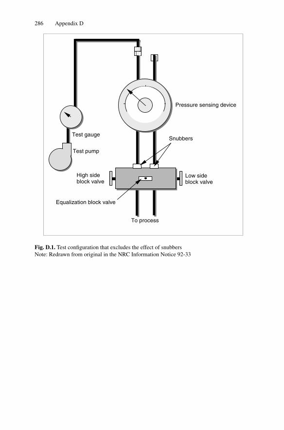
286 Appendix D
To process
Low side block valve
Snubbers
Pressure sensing device
Test pump
High side block valve
Equalization block valve
Test gauge
Fig. D.1. Test configuration that excludes the effect of snubbersNote: Redrawn from original in the NRC Information Notice 92-33
Appendix E
NRC Documents on Oil Loss
Problem in Nuclear Power Plant Pressure Transmitters
Appendix E: NRC Documents on Oil Loss Problem inNuclear Power Plant Pressure Transmitters
This appendix contains two NRC documents on the subject of oil loss in nuclearpower plant pressure transmitters. These documents are:
(1990) – NRC Bulletin No. 90-01: Loss of Fill-Oil in Transmitters ManufacturedBy Rosemount
(2004) – NRC ISSUE 176 Document: Loss Of Fill-Oil in Rosemount Transmitters
The first document above (Bulletin No. 90-01) describes the nature of the oil lossproblem and its potential consequences, and the second document (Issue 176) isprovided by the NRC to close the oil loss issue for the nuclear power industry.
OMB No.: 3150-0011
NRCB 90-01
United States
Nuclear Regulatory Commission
Office of Nuclear Reactor Regulation
Washington, D.C. 20555
March 9, 1990
NRC Bulletin No. 90-01: Loss of Fill-Oil in TransmittersManufactured by Rosemount
Addressees:
All holders of operating licenses or construction permits for nuclear power reactors.
290 Appendix E
Purpose:
This bulletin requests that addressees promptly identify and take appropriate cor-rective actions for Model 1153 Series B, Model 1153 Series D, and Model 1154transmitters manufactured by Rosemount that may be leaking fill-oil.
Description of Circumstances:
NRC Information Notice No. 89-42, “Failure of Rosemount Models 1153 and 1154Transmitters," dated April 21, 1989, was issued to alert industry to a series of reportedfailures of Rosemount Models 1153 and 1154 pressure and differential pressure trans-mitters. The reported failures occurred at Northeast Utilities’Millstone Unit 3 betweenMarch and October 1987. Subsequent investigation into the cause of the failures byRosemount confirmed that the failure mode was a gradual loss of fill-oil from thetransmitter’s sealed sensing module.
Discussion of Safety Significance:
The performance of a transmitter that is leaking fill-oil gradually deteriorates and mayeventually lead to failure. Although some failed transmitters have shown symptomsof loss of fill-oil prior to failure, it has been reported that in some cases the failureof a transmitter that is leaking fill-oil may be difficult to detect during operation. Anundetected transmitter failure has a greater adverse effect on safety system reliabilitythan a failure that would be readily detectable during normal operation. For example,electronic circuit malfunctions are routinely detected either by observing instrumentchannel readout or during periodic surveillance tests. Transmitter failures that are notreadily detectable increase the potential for common mode failure and may result in theaffected safety system not performing its intended safety function. This common modefailure potential is of increased concern when transmitter designs are particularlysusceptible to loss of fill-oil.
Discussion:
Model 1151, 1152, 1153, and 1154 Rosemount transmitters are utilized extensively innuclear power plants. Model 1153 and 1154 transmitters are supplied by Rosemount asboth seismically and environmentally qualified equipment. Model 1152 transmittersare supplied by Rosemount only as seismically qualified equipment. Model 1151transmitters are supplied by Rosemount as commercial-grade equipment.
Rosemount has indicated, to date, that failure of approximately 91 Model 1153 SeriesB, Model 1153 Series D, and Model 1154 transmitters due to loss of fill-oil from aglass to metal seal failure have been confirmed. Since the sensing module is sealed,loss of fill-oil cannot be visually confirmed without destructive analysis of the sensingmodule. NRC staff review of this issue has identified additional Model 1153 and 1154
Appendix E 291
transmitters with symptoms indicative of loss of fill-oil that may not have been broughtto Rosemount’s attention. Thus, the number of Model 1153 and 1154 transmittersthat have experienced a loss of fill-oil may be even greater than that confirmed byRosemount.
Model 1153 Series B, Model 1153 Series D, and Model 1154 transmitters, becausetheir construction incorporates the use of a metal o-ring, appear to be particularlysusceptible to loss of fill-oil due to a glass to metal seal failure. Accordingly, theNRC staff believes that the degree of susceptibility of these transmitters to loss of fill-oil warrants their being subjected to an enhanced surveillance program. In addition,certain manufacturing lots of Model 1153 Series B, Model 1153 Series D, and Model1154 transmitters have been identified by Rosemount as having had a high failurefraction due to loss of fill-oil. Specific information needed to identify transmitters thatare from these suspect lots has been provided to industry by Rosemount concurrentwith Reference 4. Accordingly, the NRC staff believes that this additional degreeof susceptibility warrants not utilizing these suspect lot transmitters in the reactorprotection or engineered safety features actuation systems.
Rosemount has indicated that failures of Model 1151 and 1152 transmitters due to lossof fill-oil have also been confirmed. The construction of Model 1151, 1152, and 1153Series A transmitters is similar to that of Model 1153 Series B, Model 1153 SeriesD, and Model 1154 transmitters (i.e., the utilization of a glass to metal seal) exceptthe construction of Model 1151, 1152, and 1153 Series A transmitters incorporatesan elastomeric o-ring instead of a metal o-ring. The NRC staff does not, at present,have sufficient information to effectively address the susceptibility of Model 1151,1152, and 1153 Series A transmitters to loss of fill-oil. Therefore, in order to obtainrelevant operational experience data, addressees are encouraged to report Model 1151,1152, and 1153 Series A, as well as Model 1153 Series B, Model 1153 Series D andModel 1154 transmitters that may have exhibited symptoms indicative of loss offill-oil or have been confirmed to have experienced a loss of fill-oil to the NuclearPlant Reliability Data System (NPRDS). In addition, while enhanced surveillance ofModel 1151, 1152, and 1153 Series A transmitters is not specifically requested by thisbulletin, addressees are encouraged to undertake such efforts on Model 1151, 1152,and 1153 Series A transmitters utilized in either safety-related systems or systemsinstalled in accordance with 10 CFR 50.62 (the ATWS rule).
Rosemount has indicated that they have instituted additional quality control and qual-ity assurance steps in the manufacturing process and modified specifications on bolttorque to reduce stress levels. These changes should minimize the potential for Model1153 Series B, Model 1153 Series D, and Model 1154 transmitter failures due to lossof fill-oil. As a result, Rosemount has indicated that transmitters of these types man-ufactured after July 11, 1989 are not subject to their May, 1989 10 CFR Part 21notification. The NRC staff has not, to date, received operational experience data thatindicates that Model 1153 Series B, Model 1153 Series D and Model 1154 transmittersmanufactured after July 11, 1989 are as susceptible to loss of fill-oil as those manufac-tured prior to July 11, 1989. Accordingly, while enhanced surveillance of transmittersof these types manufactured after July 11, 1989 is not specifically requested by thisbulletin, addressees are encouraged to undertake such efforts on these transmitters if

292 Appendix E
they are utilized in either safety-related systems or systems installed in accordancewith 10 CFR 50.62 (the ATWS rule). In addition, Model 1153 Series B, Model 1153Series D and Model 1154 transmitters manufactured after July 11, 1989 that exhibitsymptoms indicative of loss of fill-oil or are confirmed to have experienced a loss offill-oil should be reported in accordance with the report requirements of this bulletin.
The NRC staff encourages utilities to work collectively under the guidance of a tech-nical industry organization to develop and analyze an operational experience databaseconcerning all models of Rosemount transmitters. The NRC staff will continue to ob-tain and analyze operational experience data pertaining to Model 1151, 1152, 1153,and 1154 transmitters. Further regulatory action, such as requesting expansion of en-hanced surveillance activities to include Model 1151, Model 1152, and Model 1153SeriesA transmitters and Model 1153 Series B, Model 1153 Series D and Model 1154transmitters manufactured by Rosemount after July 11, 1989 or requesting replace-ment of additional suspect lot transmitters, may be taken if warranted.
Addressees may have obtained transmitters that were manufactured by Rosemount orthat contain Rosemount manufactured sensing modules from a number of differentsources. The following information is provided to facilitate addressee’s identificationof transmitters that were manufactured by Rosemount or that contain Rosemountmanufactured sensing modules:
– Rosemount has indicated that unauthorized remanufacturers and refurbishers existfor Model 1151 transmitters. Unauthorized remanufacturers and refurbishers mayalso exist for Model 1152, 1153, and 1154 transmitters.
– All Model 1153 and 1154 transmitters, whether obtained directly from Rose-mount, obtained through intermediary suppliers, or provided as an integral partof another component (such as an emergency diesel generator), should a) indicatemanufacture by Rosemount, b) have a distinctive Rosemount model and serialnumber, c) have the physical profile characteristics of a Rosemount transmitter,and d) have a blue or stainless steel housing. Rosemount has indicated that Model1153 and 1154 transmitters are not provided to other manufacturers for resaleunder a different brandname. In addition, a simplified diagram that describes thetypical physical characteristics of a Rosemount transmitter is provided by Attach-ment 1.
– Model 1152 transmitters, except as noted below, should a) indicate manufactureby Rosemount, b) have a distinctive Rosemount model and serial number, c) havethe physical profile characteristics of a Rosemount transmitter, and d) have ablue or stainless steel housing. Rosemount has indicated that they have suppliedModel 1152 transmitter sensing modules to Bailey Controls (formerly BaileyMeter). Bailey manufactured transmitters that contain Rosemount manufacturedModel 1152 sensing modules have gray housings that appear slightly differentthan Rosemount housings.
– Model 1151 transmitters, except as noted below, should a) indicate manufactureby Rosemount, b) have a distinctive Rosemount model and serial number, c) havethe physical profile characteristics of a Rosemount transmitter, and d) have a bluehousing. Model 1151 transmitters manufactured by Rosemount may have been

Appendix E 293
supplied for use in nuclear power plants by other original equipment manufac-turers. These transmitters should have the physical profile characteristics of aRosemount transmitter and have a blue housing. Fisher Controls may also offerfor resale under their own brand name Model 1151 transmitters purchased fromRosemount. These transmitters should have the physical profile characteristics ofa Rosemount transmitter, but have a green housing.
The earliest symptom a Model 1153 Series B, Model 1153 Series D, or Model 1154transmitter may exhibit during normal operation prior to failure if it is leaking fill-oilis:
– a sustained drift
The symptoms a Model 1153 Series B, Model 1153 Series D, or Model 1154 transmit-ter may exhibit during normal operation subsequent or immediately prior to failure ifit is leaking fill-oil include:
– a sustained drift
– an abrupt decreasing drift (for high range gauge or absolute transmitters)
– a change in process noise including amplitude variations, “one-sided-noise," orasymmetric noise distributions
– slow response to or inability to follow planned or unplanned plant Transients
The symptoms a Model 1153 Series B, Model 1153 Series D, or Model 1154 trans-mitter may exhibit during calibration activities if it is leaking fill-oil include:
– inability to respond over the entire design range
– slow response to either an increasing or decreasing test pressure
– a sustained zero or span shift
The NRC staff believes these symptoms can also be utilized to detect Model 1151,1152, and 1153 Series A transmitters that may be experiencing a loss of fill-oil.
The NRC staff has reviewed the information which has been provided by Rosemount,including References 1, 2, 3, and 4, to assist industry in detecting transmitters thatmay be leaking fill-oil. The NRC staff has concluded that Rosemount has providedsufficient bases to support their proposed diagnostic procedures (trending calibrationdata, trending operational data, sluggish transient response, and process noise analy-sis) for detecting whether a transmitter may be leaking fill-oil.Accordingly, the actionsrequested in this bulletin are intended to reflect these diagnostic procedures. How-ever, the NRC staff has concluded that Rosemount has not provided sufficient basesto support their proposed methodology (pressure versus time-in-service) for iden-tifying which transmitters should be subject to an enhanced surveillance program.Specifically, the NRC staff believes that the methodology utilized by Rosemount tosupport their proposed pressure versus time-in-service criteria for identifying whichtransmitters should be subject to an enhanced surveillance program does not providethe necessary high degree of confidence that this failure mode will not occur.

294 Appendix E
Rosemount had initially indicated that Model 1153 Series B, Model 1153 Series D,and Model 1154 transmitters that were experiencing a loss of fill-oil should fail withinapproximately 36 months of in-service time. Recent information indicates that the rateof loss of fill-oil is application and pressure dependent. Although transmitters subjectto continuous high-pressure (e.g. reactor operating pressures) may fail within thistimeframe, transmitters utilized in low-pressure systems or not subject to continuoushigh-pressure may take longer to fail.
General Design Criterion (GDC) 21 “Protection System Reliability and Testability"of 10 CFR 50, Appendix A requires the protection system to be designed for highfunctional reliability and with sufficient capability to allow periodic testing of itsfunctioning when the reactor is in operation in order to readily detect failures ofsubcomponents and subsystems within the protection system as well as loss of therequired protection system redundancy as they occur. 10 CFR 50.55a(h) requiresthat protection systems meet the Institute of Electrical and Electronics EngineersStandard: “Criteria for Protection Systems for Nuclear Power Generating Stations"(IEEE-279). IEEE-279 states that means shall be provided for checking, with a highdegree of confidence, the operational availability of each system input sensor duringreactor operation. Thus, the NRC staff concludes that facilities that utilize transmittersthat may be particularly susceptible to loss of fill-oil may not be in full compliance withthese regulations because undetected transmitter failure could occur. Accordingly, theNRC staff requests that addressees take the actions requested below.
Requested Actions:
Operating Reactors
All holders of operating licenses for nuclear power reactors are, within 120 days afterreceipt of this bulletin, requested to:
1. Identify Model 1153 Series B, 1153 Series D, and Model 1154 pressure or dif-ferential pressure transmitters, excluding Model 1153 Series B, 1153 Series D,and Model 1154 transmitters manufactured by Rosemount subsequent to July11, 1989, that are currently utilized in either safety-related systems or systemsinstalled in accordance with 10 CFR 50.62 (the ATWS rule).
2. Determine whether any transmitters identified in Item 1 are from the manufactur-ing lots that have been identified by Rosemount as having a high failure fractiondue to loss of fill-oil. Addressees are requested not to utilize transmitters fromthese suspect lots in the reactor protection or engineered safety features actuationsystems; therefore, addressees are requested to develop and implement a pro-gram to replace, at the earliest appropriate opportunity, transmitters from thesesuspect lots in use in the reactor protection or engineered safety features actuationsystems.
3. Review plant records (for example, the three most recent calibration records) as-sociated with the transmitters identified in Item 1 above to determine whether any

Appendix E 295
of these transmitters may have already exhibited symptoms indicative of loss offill-oil. Appropriate operability acceptance criteria should be developed and ap-plied to transmitters identified as having exhibited symptoms indicative of loss offill-oil from this plant record review. Transmitters identified as having exhibitedsymptoms indicative of loss of fill-oil that do not conform to the operability ac-ceptance criteria should be addressed in accordance with the applicable technicalspecification. Transmitters identified as having exhibited symptoms indicative ofloss of fill-oil that do not conform to the operability acceptance criteria and arenot addressed in the technical specifications should be replaced at the earliestappropriate opportunity.
4. Develop and implement an enhanced surveillance program to monitor transmit-ters identified in Item 1 for symptoms of loss of fill-oil. This enhanced surveillanceprogram should consider the following or equally effective actions:
a) Ensuring appropriate licensee personnel are aware of the symptoms that atransmitter, both during operation and during calibration activities, may ex-hibit if it is experiencing a loss of fill-oil and the need for prompt identificationof transmitters that may exhibit these symptoms;
b) Enhanced transmitter monitoring to identify sustained transmitter drift;
c) Review of transmitter performance following planned or unplanned plant tran-sients or tests to identify sluggish transmitter response;
d) Enhanced awareness of sluggish transmitter response to either increasing ordecreasing test pressures during calibration activities;
e) Development and implementation of a program to detect changes in processnoise; and
f) Development and application to transmitters identified as having exhibitedsymptoms indicative of loss of fill-oil of an appropriate operability acceptancecriteria. Transmitters identified as having exhibited symptoms indicative ofloss of fill-oil that do not conform to the operability acceptance criteria shouldbe addressed in accordance with the applicable technical specification. Trans-mitters identified as having exhibited symptoms indicative of loss of fill-oilthat do not conform to the operability acceptance criteria and are not addressedin the technical specifications should be replaced at the earliest appropriateopportunity.
5. Document and maintain in accordance with existing plant procedures a basis forcontinued plant operation covering the time period from the present until suchtime that the Model 1153 Series B, 1153 Series D, and Model 1154 transmittersfrom the manufacturing lots that have been identified by Rosemount as havinga high failure fraction due to loss of fill-oil in use in the reactor protection orengineered safety features actuation systems can be replaced. In addition, whileperforming the actions requested above, addressees may identify transmittersexhibiting symptoms indicative of loss of fill-oil that do not conform to the es-tablished operability acceptance criteria and are not addressed in the technicalspecifications. As these transmitters are identified, this basis for continued plant
296 Appendix E
operation should be updated to address these transmitters covering the time pe-riod from the time these transmitters are identified until such time that thesetransmitters can be replaced. When developing and updating this basis for con-tinued plant operation, addressees may wish to consider transmitter diversity andredundancy, diverse trip functions (a separate trip function that may also pro-vide a corresponding trip signal), special system and/or component tests, or (ifnecessary) immediate replacement of certain suspect transmitters.
Construction Permit Holders
1. All construction permit holders that anticipate receiving an operating licensewithin 120 days after receipt of this bulletin are requested to perform Items 1,2, 4, and 5 of Requested Actions for Operating Reactors within 120 days afterreceipt of this bulletin.
2. All construction permit holders that do not anticipate receiving an operatinglicense within 120 days after receipt of this bulletin are requested to, prior to thedate scheduled for fuel loading, complete Items 1 and 4 of Requested Actionsfor Operating Reactors and to address the intent of Items 2 and 5 of RequestedActions for Operating Reactors by:
a) Identifying and replacing Model 1153 Series B, 1153 Series D, and Model1154 transmitters from the manufacturing lots that have been identified byRosemount as having a high failure fraction due to loss of fill-oil that areinstalled in the reactor protection or engineered safety features actuation sys-tems; and
b) Documenting and maintaining in accordance with existing plant procedures abasis for continued plant operation that addresses transmitters that, subsequentto fuel loading, are identified as exhibiting symptoms indicative of loss of fill-oil that do not conform to the established operability acceptance criteria andare not addressed in the technical specifications covering the time period fromthe time these transmitters are identified until such time that these transmitterscan be replaced.
Reporting Requirements:
Operating Reactors
1. Provide, within 120 days after receipt of this bulletin, a response that:
a) Confirms that Items 1, 2, 3, 4, and 5 of Requested Actions for OperatingReactors have been completed.
b) Identifies the indicated manufacturer; the model number; the system the trans-mitter was utilized in; the approximate amount of time at pressure; the correc-tive actions taken; and the disposition (e.g., returned to vendor for analysis)

Appendix E 297
of Rosemount Model 1153 Series B, Model 1153 Series D, and Model 1154transmitters that are believed to have exhibited symptoms indicative of lossof fill-oil or have been confirmed to have experienced a loss of fill-oil. Thisshould include Model 1153 manufactured after July 11, 1989.
c) Identifies the system in which the Model 1153 Series B, 1153 Series D, andModel 1154 transmitters from the manufacturing lots that have been identifiedby Rosemount as having a high failure fraction due to loss of fill-oil areutilized and provides a schedule for replacement of these transmitters whichare in use in the reactor protection or engineered safety features actuationsystems.
2. Model 1153 Series B, Model 1153 Series D and Model 1154 transmitters that,subsequent to providing the response required by Item 1 above, exhibit symptomsof loss of fill-oil or are confirmed to have experienced a loss of fill-oil should bereviewed for reportability under existing NRC regulations. If determined not tobe reportable, addressees are requested to document and maintain, in accordancewith existing plant procedures, information consistent with that requested in Item1 b) above for each transmitter identified.
Although not required by this bulletin, addressees are encouraged to report infor-mation consistent with that requested in Item 1 b) above through the Nuclear PlantReliability Data System (NPRDS) for all Rosemount Model 1151, 1152, 1153 and1154 transmitters that exhibit symptoms indicative of a loss of fill-oil or are confirmedto have experienced a loss of fill-oil.
Construction Permit Holders
1. All holders of construction permits that anticipate receiving an operating licensewithin 120 days after receipt of this bulletin are required to, within 120 days afterreceipt of this bulletin, provide a response that:
a) Confirms that Items 1, 2, 4, and 5 of RequestedActions for Operating Reactorshave been completed; and
b) Identifies the system in which the Model 1153 Series B, 1153 Series D, andModel 1154 transmitters from the manufacturing lots that have been identifiedby Rosemount as having a high failure fraction due to loss of fill-oil are utilizedand provides a schedule for replacement of these transmitters which are in usein the reactor protection or engineered safety features actuation systems.
2. All holders of construction permits that do not anticipate receiving an operatinglicense within 120 days after receipt of this bulletin are required to, prior to thedate scheduled for fuel loading, provide a response that confirms that Item 2 ofRequested Actions for Construction Permit Holders has been completed.
3. Model 1153 Series B, Model 1153 Series D and Model 1154 transmitters that,subsequent to providing the response required by Item 1 or 2 above, exhibit symp-toms of loss of fill-oil or are confirmed to have experienced a loss of fill-oil should
298 Appendix E
be reviewed for reportability under existing NRC regulations. If determined notto be reportable, addressees are requested to document and maintain, in accor-dance with existing plant procedures, information consistent with that requestedin Item 1 b) of the Reporting Requirements for Operating Reactors above foreach transmitter identified.
Although not required by this bulletin, addressees are encouraged to report informationconsistent with that requested in Item 1 b) of the Reporting Requirement for OperatingReactors through the NPRDS for all Rosemount Model 1151, 1152, 1153 and 1154transmitters that exhibit symptoms indicative of loss of fill-oil or are confirmed tohave experienced a loss of fill-oil.
As has been previously indicated, the NRC staff believes that the methodology utilizedby Rosemount to support their proposed pressure versus time-in-service criteria foridentifying which transmitters should be subject to an enhanced surveillance programdoes not provide the necessary high degree of confidence that this failure mode will notoccur. Additional operational experience data, such as that to be generated in responseto this bulletin, could be utilized by industry either to provide additional insight asto the appropriateness of Rosemount’s pressure versus time-in-service criteria or todevelop bases for staff consideration of an amendment to or termination of the actionsrequested by this bulletin. Accordingly, the NRC staff encourages utilities to workcollectively under the guidance of a technical industry organization to develop anoperational experience database concerning all models of Rosemount transmitters.
The written reports required above shall be addressed to the U.S. Nuclear RegulatoryCommission, ATTN: Document Control Desk, Washington, D.C. 20555, and shallbe submitted under oath or affirmation pursuant to the provisions of Section 182a,Atomic Energy Act of 1954, as amended and 10 CFR 50.54(f). In addition, a copyshall be submitted to the appropriate Regional Administrator.
Backfit Discussion
The objective of the actions requested in this bulletin is to ensure that transmitterfailures due to loss of fill-oil are promptly detected. Loss of fill-oil may result in atransmitter not performing its intended safety function.
The actions requested in this bulletin represent new staff positions and thus, this re-quest is considered a backfit in accordance with NRC procedures. Because establishedregulatory requirements exist but were not satisfied, this backfit is to bring facilitiesinto compliance with existing requirements. Therefore, a full backfit analysis wasnot performed. An evaluation of the type discussed in 10 CFR 50.109(a)(6) was per-formed, including a statement of the objectives of and reasons for the actions requestedand the basis for invoking the compliance exception. It will be made available in thePublic Document Room with the minutes of the 179th meeting of the Committee toReview Generic Requirements.
This request is covered by Office of Management and Budget Clearance Number3150-0011 which expires January 31, 1991. The estimated average burden hours are
Appendix E 299
6 person-hours per transmitter per licensee. This includes assessing the requestedactions, gathering and reviewing plant records, analyzing the data obtained fromthe plant records, and preparing the required response. This does not include devel-oping and implementing the requested enhanced surveillance program or replacingtransmitters from the manufacturing lots that have been identified by Rosemount ashaving a high failure fraction due to loss of fill-oil that are utilized in the reactorprotection or engineered safety features actuation systems. Send comments regardingthis burden estimate or any other aspect of this collection of information, includingsuggestions for reducing this burden, to the Information and Records ManagementBranch, Division of Information Support Services, Office of Information ResourcesManagement, U.S. Nuclear Regulatory Commission, Washington, D.C. 20555; andto the Paperwork Reduction Project (3150-0011), Office of Management and Budget,Washington, D.C. 20503.
If you have any questions about this matter, please contact one of the technical contactslisted below or the appropriate NRR project manager.
Charles E. Rossi, Director
Division of Operational Events Assessment
Office of Nuclear Reactor Regulation
Technical Contacts: Jack Ramsey, NRR, (301) 492-1167Vince Thomas, NRR, (301) 492-0786
References:
1. Rosemount Technical Bulletin No. 1 dated May 10, 1989
2. Rosemount Technical Bulletin No. 2 dated July 12, 1989
3. Rosemount Technical Bulletin No. 3 dated October 23, 1989
4. Rosemount Technical Bulletin No. 4 dated December 22, 1989
Attachments:
1. Typical Physical Characteristics of a Rosemount Transmitter
2. List of Recently Issued NRC Bulletins

300 Appendix E
August 2004
Issue 176: Loss of Fill-Oil in Rosemount Transmitters
Description
Historical Background
The Rosemount Transmitter Review Group (RTRG) was established1659 to performan assessment of the actions taken to address Rosemount transmitter oil-loss concerns.This assessment included an evaluation of the adequacy of the information and actionsspecified in NRC Bulletin 90-01,1658 Supplement 1, which informed licensees ofactivities undertaken by the NRC and the industry in evaluating and addressing loss offill-oil in Rosemount transmitters manufactured prior to July 11, 1989, and requestedlicensees to take actions to resolve the concerns.
An action plan was developed by the staff and integrated the following RTRG rec-ommendations to address Rosemount transmitter loss of fill-oil concerns: (1) conducttemporary instruction (TI) inspections to verify commitments made by licensees toaddress the requested actions of NRC Bulletin 90-01,1658 Supplement 1, and to gatherplant-specific data on Rosemount transmitter failures; (2) establish a dialogue withRosemount, Inc., on Rosemount transmitter failure information; (3) review NPRDSdata on Rosemount transmitter performance; and (4) review EPRI Report TR-102908,“Review of Technical Issues Related to the Failure of Rosemount Pressure Transmit-ters Due to Fill-Oil Loss," dated August 1994. This issue was identified in an NRRmemorandum1601 to RES in February 1996.
Safety Significance
Loss of fill-oil in Rosemount transmitters was determined to be a potentially unde-tected means of common mode failure. Such failures could result in loss of automaticreactor protection and engineered safety feature actuations.
Possible Solution
The staff determined that actions were needed by licensees to ensure that safety-related functions were maintained. These actions were first identified in Bulletin90-011658 and subsequently modified in Bulletin 90-01,1658 Supplement 1. The timeframe for this action plan was based on the fact that licensees had implemented therequested actions of Bulletin 90-01,1658 Supplement 1, and the plan was intendedonly as confirmation of the adequacy of the actions called for in the Bulletin.1658
The activities specified in the action plan were completed as a follow-up and verifica-tion of the implementation of the requested actions in Bulletin 90-01,1658 Supplement
Appendix E 301
1. Licensees addressed the common mode failure concerns by either replacing affectedtransmitters with newly designed transmitters which corrected the oil leakage prob-lem, or subjecting affected transmitters to enhanced surveillance monitoring to ensuretheir proper performance. A two-year period was established for completing the nec-essary verification activities recommended by the RTRG including TI inspections andreviews of recent Rosemount transmitter performance.
Conclusion
Temporary Instruction (TI) 2515/122, “Evaluation of Rosemount PressureTransmitterPerformance and Licensee Enhanced Surveillance Programs," was issued on March17, 1994 and inspections were initiated in May 1994. Based on the results of the TIeffort, the staff determined that licensees were effectively addressing the Rosemounttransmitter loss of fill-oil issue by, in general, following the requested actions ofBulletin 90-01,1658 Supplement 1, and the manufacturer’s drift trending guidance.
The staff met periodically (between January 1994 and September 1995) with Rose-mount, Inc. to exchange information on Rosemount transmitter performance. In addi-tion, the staff completed NPRDS reviews for Rosemount transmitter failure informa-tion during the same period. Based on the information presented by Rosemount, Inc.and the results of the NPRDS reviews, the staff concluded that there was a significantdecrease in the number of fill-oil failures since the issuance of Bulletin 90-01,1658
Supplement 1.
On February 15, 1995, the staff completed its review of EPRI Report TR-102908and confirmed that it was substantially in agreement with the previous conclusions,guidance, and requested actions contained in Bulletin 90-01,1658 Supplement 1.
Based on the results of the above activities completed, the staff confirmed that all per-tinent information regarding loss of fill-oil in Rosemount transmitters was containedin Bulletin 90-01,1658 Supplement 1, and Rosemount technical guidance. Therefore,the staff concluded that the safety concern of the issue had been effectively resolvedby the actions taken and no changes or additional actions were warranted. Thus, thisissue was RESOLVED and no new requirements were issued.
Index
accelerometer 8accuracy 34aging 34ASTM 25
biot modulus 100boiling water reactor 1Bourdon tube 143BWR level measurement problem 183bypass loop 121bypass manifolds 121
calibration 34, 44callendar 30CANDU 10cold shutdown test 126common mode drift 38condensate pot 178core-exit thermocouple 48corrosive thinning 47CRDM (control rod drive mechanism) 15cross-calibration 3, 38, 51, 63, 64current loop 144
degradation 38differential pressure 144drift 38dynamic response problem 43dynamic testing 3
eigenvalue 100electromotive force 45EMF (Electromotive Force) 38, 45
ensemble averaging to smooth LCSR data103
EPRI 22equalizing valve 178extension lead 43extrapolation 82
fiber-optic pressure transmitter 174flow anomalies 10force-balance 143frequency domain 198
halden reactor project 21
IAEA 24IEC 25IEEE 25impedance 13inductance 15in-situ testing 39instability 68insulation resistance 39, 44IR 44ISA 25isolation valve 178
Johnson Noise technique 51
LCSR (loop current step response) 13, 20,90, 97
LCSR assumption 107LCSR parameter optimization 116LCSR transformation 99lead-wire imbalance 47
304 Index
LER (Licensee Event Report) database 39lift coil 15LOCA 30lowpass filters 187
modal time constants 99motion-balance 143movable coil 15
neutron detectors 8NIST (National Institute of Standards and
Technology) 39noise analysis technique 90, 195nonuniformity error 69
oil loss 213, 217on-line monitoring 3
passive maintenance 27pink noise technique 207plant computer 59, 71plunge test 90PSD 198pulsation dampers 187
qualified life 149
recalibration procedure 78redundancy 3repeatability 41response time 4, 31, 41response-time testing 89reverse-connected thermocouple 49rod drop time 15
root valve 178RTD (Resistance Temperature Detector) 3,
29, 41
self-heating 42, 118, 126self-heating index 90sensing element 42sensing line 5, 177sensing-line blockage 189, 227sensing line leak 233shared sensing line 183, 235smart sensor 173snubbers in sensing line 187SPRT (Standard Platinum Resistance
Thermometer) 42stability 42stationary gripper coil, movable coil 15
TDR (time domain reflectometry) 14temperature stratification 118temperature streaming 31, 118thermocouples 10, 20, 29thermowell 23, 42, 47, 107time constant 42traditional cross-calibration 54
ultrasonic flow sensor 7uncertainty 42, 65
venturi fouling 6vibration 8
well-type sensor 42wet-type sensor 42wireless sensor 175