design of the htgr for process heat applications
TRANSCRIPT

GA-A15875
DESIGN OF THE HTGR FOR PROCESS HEAT APPLICATIONS
by D. L. VRABLE and R. N. QUADE
MAY 1980
GENERAL ATOMIC COMPANY DISTfl!BUTIOil OF TlilS om:UPWH IS Uii!LIMITED

DISCLAIMER
This report was prepared as an account of work sponsored by an agency of the United States Government. Neither the United States Government nor any agency Thereof, nor any of their employees, makes any warranty, express or implied, or assumes any legal liability or responsibility for the accuracy, completeness, or usefulness of any information, apparatus, product, or process disclosed, or represents that its use would not infringe privately owned rights. Reference herein to any specific commercial product, process, or service by trade name, trademark, manufacturer, or otherwise does not necessarily constitute or imply its endorsement, recommendation, or favoring by the United States Government or any agency thereof. The views and opinions of authors expressed herein do not necessarily state or reflect those of the United States Government or any agency thereof.

DISCLAIMER
Portions of this document may be illegible in electronic image products. Images are produced from the best available original document.

NOTICE
This report was prepared as an account of work sponsored by an agency of the United States Government. Neither the United States nor any agency thereof, nor any of their employees, makes any warranty, expressed or implied, or assumes any legal liability or responsibility for any third party's use or the results of such use of any information, apparatus, product or process disclosed in this report, or represents that its use by such third party would not infringe privately owned rights.

..
•
GA-A15875 ----DISCLAIMER----..,
This book was prepared as an account olwrork sponsored by an agency of the United States Governmen1. Neither the United States Government nor any ogcncy thereof, nor any of their employees, makes any warramv. express or implied, or assumes any legal liability or responsibility for the accuracy, completeness, or usefulness of any information, apparatus. product. or process disclosed, or
! represems that its use v.ould not infringe privatety owned rights. Reference herein to any specific , commercial product, process, or. service by trade name. trademark, manufacturer, or otherwise, does
not necessarily constitute or imply iiS endorsemem, recommendation, or favoring by the United States Government or any agency thereof. The views and opinions of authors expressed herein do not ~ necessarll~ state or reflect those of the United States Governmem or any agency thereof, 1
~ ~ --- ~- . --. -- -- -~i
DESIGN OF THE HTGR '
FOR PROCESS HEAT APPLICATIONS
by D. L. VRABLE and R. N. QUADE
This is a preprint of a paper to be presented at the 15th lntersociety Energy Conversion Engineering Conference, August 18-22, 1980, Seattle, Washington, and to be published in the Proceedings.
Work supported by Department of Energy
Contract DE-AT03-76SF71 061
GENERAL ATOMIC PROJECT 7212 MAY 1980
GENERAL ATOMIC COMPANY
DISTR!BUT!OH OF THIS OOCU~1ENT IS UNliMITED

•
"
DESIGN OF THE HTGR FOR PROCESS HEAT APPLICATIONS
D. L. Vrable and R. N. Quade General Atomic Company
San Diego, California
Abstract
The high-temperature gas-cooled reactor (HTGR) offers a unique heat source for process heat applications, since its operating temperature is substantially higher than other nuclear reactor types. This paper discusses a design study of an advanced 842-MW(t) HTGR with a reactor outlet temperature of 850°C (1562°F), coupled with a chemical process whose product is hydrogen (or a mixture of hydrogen and carbon monoxide) generated by steam reforming of a light hydrocarbon mixture.
This paper discusses the plant layout and design for the major components of the·primary and secondary heat transfer systems. Typical parametric system study results illustrate the capability of a computer code developed to model the plant performance and economics.
I. Introduction
The high-temperature heat available from the high-temperature gas-cooled reactor (HTGR) makes it suitable for many process applications. The highgrade heat can be utilized to produce hydrogen and synfuel using coal, lignite! residual oil, or oil shale as the carbon source. ,2 It can also serve as the heat source for thermochemical watersplitting processes to produce hydrogen without carbon.3 It may be useful in large-scale energy tran.sport and storage systems for industrial or utility application.4,5
The HTGR process heat plant discussed in this paper envisages a nuclear-chemical process whose product is hydrogen (or a mixture of hydrogen and carbon monoxide) generated by steam reforming of a light hydrocarbon mixture. The reactor energy is transported to an externally located process plant by an intermediate heat transport loop. The intermetih.te loop provides an additiOi141 boundary betweei'l the nuclear heat source and the process, thereby enhancing plant safety and offering considerable flexibility for alternate applications.
This plant differs from previous plant designs discussed! in that the reactor outlet temperature has been reduced fr.om 950°C (1742°F) to 850°C
.(1562°F). This reduction in temperature allows the HTGR proceso heat plant tu be considered for nearterm deployment.
The integration of this unique high-temperature heat source with various process hea.t applications requires a sophisticated coupling of the major process system parameters of both the nuclear heat source (NHS) and end-process application. This coupling should include the effects of overall performance and plant economics. Part of the nuclear process heat program consisted of developing a computer model fur the NHS and the associated process plant. This computer code, called the Process Heat Reactor Evaluation and Design (PHRED) code, was developed to do the following:
1
1. Calculate the complete reactor plant mass flow and heat balance for a wide variety of independent variables (e.g., core outlet temperature, primary loop pressure, process temperature).
2. Specify design operating conditions for all major components and calculate the size of the components based on their performance
·requirements [e.g., intermediate heat exchanger (IHX), helium circulator, steam generator, prestressed concrete reactor vessel (PCRV)).
3. Calculate the capital and operating costs of the entire nuclear heat source and associated process plant.
4. Couple to any availabale multi-variable direct search optimization program for system optimization studies.
II. Nuclear Heat Source (NHS) Description
Plant Description
The HTGR offers a unique heat source for process heat applications, since its operating temperature is substantially higher than other nuclear reactor types. This high-temperature capability allows nuclear energy to be substituted for fossil energy in the production of synthetic fuels from coal.
The HTGR process heat reactor is a version of the electricity-"producing Fort St. Vrain HTGR, operating for the Public Service Company of Colorado. The selected thermal rating of 842 MW(t), which corresponds to the Fort St. Vrain reactor, is also commensurate with process heat user requirements. As in other UTOReo, the entire primary coolant system is contained in a PCRV, which provides the necessary biological shielding in addit:l.on to containing pressure. The reactor core has ceramic-coated uranium/thorium fuel particles, employs graphite as the moderator and structural material, and utilizes helium as the coolant. The helium primary coolant is chemically inert, has a low stored energy content, and remains in the gaseous phase under all conceivable operating conditiOns. These passive features of the core and PCRV and the choice of coolant result in a unique nuclear heat source with a h1&h degree of inherent safety.
Figure 1 shows an isometric illustration of the primary system components inside the PCRV. Thermal energy is transf,erred from the reactor core to the externally located process plant by an inter.mediate heat transport loop. In addition to providing high_. temperature thermal energy for chemical process:lng (i.e., steam-methane reforming), the nuclear heat generates high-temperature, high-pressure steam for process consumption and plant (nuclear and process) electrical needs.
•
,.
CORE
PCRV
CORE AUXILIARY COOLING SYSTEM
INTERMEDIATE HEAT EXCHANGER
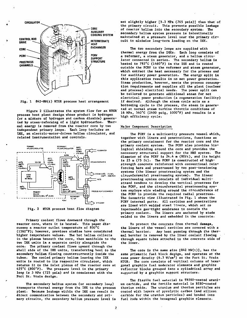
Fig. 1 842-MW(t) HTGR proc.ess heat arrangement
Figure 2 illustrates the system flow for an HTGR. process heat plant design whose product is hydrogen (or a mixture of hydrogen and carbon dioxide) generated by steam-reforming of a light hydrocarbon. Thermal energy is removed from the reactor core by two independent primary loops. Each loop includes an IHX, an electric-motor-driven helium circulator, and related instrumentation and controls.
SECONDARY HELIUIII CIRCULATOR
PRIMARY L=~====t • ~l~~':s ll.tM 11 to6 LBIHRI I
L----------------------~ PCAV
SECONOARV t.l£ttUt.l
FEEOWATER
STEAM 51D°C · 11.2MPi :~:.lflt -l!IUOf'SIAI
FEED
EFFLUENT
Fig. 2 HTGR process heat flow diagram
Primary coolant flows downward through the reactor core, where it is heated. This paper discusses a reactor outlet temperature of 850°C (1562°F); however, previous studies have considered higher temperature values. The hot helium collects in the plenum beneath the core, then manifolds to the two IHX units in a separate cavity alongside the core. The primary coolant flows upward through the shell side of the IHX units, transferring heat to the secondary helium flowing countercurrently inside the tubes. The cooled primary helium leaving the IHX units is routed to its respective circulator, which returns it to the inlet plenum of the reactor core at 425°C (800°F). The pressure level in the primary loop is 5 MPa (725 psia) and is consistent with the Fort St. Vrain design.
The secondary helium system (or secondary loop) transports thermal energy from the IHX to the process plant. Because leakage within the IHX can result in direct communication between the secondary and primary circuits, the secondary helium pressure level is
2
set slightly higher [5.3 MPa (765 psia)] than that· of the primary circuit. This prevents possible leakage of reactor helium into the secondary system. The secondary helium system pressure is intentionally maintained at a pressure level near the primary circuit to minimize long-term loading on the IHX.
The two secondary loops are supplied with thermal energy from the IHXs. Each loop consists of a reformer, a steam generator, and a helium circulator connected ·in series. The secondary helium is heated to 793°C (1460°F) in the IHX and is routed outside the PCRV to the reformer and steam generator, which extract the heat necessary for the process and for auxiliary power generation. The energy split in this application results in no net power generation. Steam production, however, meets the process consumption requirements and supplies all the plant (nuclear and process) electrical needs. The power split can be tailored to generate additional steam for net electrical power production (a cogeneration facility) if desired. Although the steam cycle acts as a bottoming cycle to the process, the steam is generated at normal steam turbine throttle conditions of 16 MPa, 540°C (2400 psig, 1000°F) and results in a high efficiency cycle.
Major Component Description
The PCRV is a multicavity pressure vessel which, together with liners and penetrations, functions as the primary containment for the reactor core and the primary coolant system. The PCRV also provides biological shielding around the core and provides the necessary structural support for the NHS system. The diameter of the PCRV is 24.4 m (80ft), and its height is 23 m (75 ft). The PCRV is constructed of highstrength concrete rei-nforced with conventional reinforcing bars and prestressed by two post-tensioning systems (the linear prestressing system and the circumferential prestressing system). The linear prestressing system consists of individual multistrand tendons to develop the vertical prestress for the PCRV, and the circumferential prestressing system employs wire winding around the circumference of the PCRV to provide the required radial prestress. The isometric view illustrated in Fig. 1 shows the PCRV internal parts. All cavities and penetrations are lined with welded steel lf.ners, which act ao impermeable gas-tight membranes to contain the primary coolant. The liners are anchored by studs welded to the liners and embedded in the concrete.
To protect the concrete from thermal damaga, the liners of the vessel cavities are covered with a thermal barrier. Any heat passing through the thermal barrier is removed by the liner coolant flowing through square tubes attached to the concrete side of the liner.
The core is the same size [842 MW(t)], has the same prismatic fuel block design, and operates at the same power density (6.3 W/cm3) as the Fort St. Vrain HTGR. The core consists of ve,rtical columns of hexagonal graphite fuel moderator elements and graphite reflector blocks grouped into a cylindrical array and supported by a graphite support structure.
The fissile fuel ~L~tlal is TRISO-coated uranium carbide, and the fertile material is BISO-coated thorium oxide. The uranium and thorium particles are coated with layers of pyrolytic carbon (and silicon carbide for the uranium particles) and bonded into fuel rods within the hexagonal graphite elements.

•
..
The particle coatings provide the primary barrier for fission product retention. Either high-enriched uranium (HEU) or low-enriched uranium (LEU) cores are possible. The basic core structural material is nuclear-grade graphite machined in hexagonal blocks. These blocks also serve as the moderator and heat transfer medium between fuel and coolant.
The IHX, a nuclear-grade safety-class component, transfers heat from the primary helium circuit to the secondary helium circuit during normal operation·and removes heat during emergency core cooling. It has been designed as a modularized straight-tube counterflow heat exchanger to obtain (1) geometric heat exchange proportions most consistent with the PCRV envelope, (2) minimum heat temperature gradients, (3) reduced helium pressure loss, and (4) minimum potential for flow-induced tube vibrations. The IHX design is similar to helium-to-helium heat exchangers used in the HTGR gas turbine plant. Although normal operation is in a near-pressure-balanced condition, the design basis is predicated on the loss of the secondary loop pressure putting the tubes into compression. The current tubing material is Inconel 617. An extensive high-temperature materials program is in progress for this application.
The steam-methane reformer transfers heat from the helium loop to the reformer feedstock in the presence of a nickel catalyst. It is, in effect, an axial counterflow convective heat exchanger, but it has space provided on the tube side to include the catalyst material.
Many different concepts, which appear to satisfy basic reformer requirements, are possible. However, this paper considers a design concept used in the fossile-fired reforming industry for many years and adapted to convective heating. This concept utilizes a she11-and-tube heat exchanger, which has tubes large enough to contain the catalyst material in a stacked particie bed. The feedstock enters on the tube side of the heat exchanger and flows over the catalyst particles while being heated by the tube walls. The conversion reaction takes place during passage through the bed, requiring that heat be supplied to the tubes over the entire active length. In fossil-fired reformers, this heat input is supplied by radiant energy from many fuel burners or gas jets adjacent to a row of catalyst tubes. To adapt this concept tn A secondary loop convective heat source, the tubes are grouped together to form a gasto-gas tube-and-shell heat exchanger. The hot secondary helium enters on the shell side at the hot end of the catalyst tubes, flows counter to the product gas around the tubes, and exits at the cold end.
III. System Studies
Cuwputer Code Description
The PHRED computer cod~ prepares a complP.t~
plant design, calculates plant performance, and estimates the plant capital and operating costs based on input values of 52 independent design parameters for the process heat HTGR. PHRED determines the product cost relationship to the major plant design parameters. The code can also be coupled with available multi-variable direct-search optimization programs to to select design parameters for mini~l product cost or for other selected figur.es.
PHRED is necessarily a special-purpose code, applicable (in its present form) only to HTGR plants
3
of the type hclng developed by General Atomic Company. Development of PHRED started in fiscal year 1977; however, substantial background information existed from earlier codes developed for the HTGR steam cycle and gas turbine plants. As a result, the the PHRED code represents a third-generation sophistication.
PHRED first establishes a consistent set of design and cost parameters for a base case, which normally corresponds to the current reference design. It then defines other cases by changing one or more independent design variables from their base values. In most instances, it obtains design parameters and costs by calculating differences or ratios relative to the base case. The code objective is to predict the relative plant design performance impact on the product cost from case to case.
Figure 3 illustrates a simplified system flow schematic of the·HTGR process heat plant. The system can be subdivided into four major fluid loops: (1) primary helium, (2) secondary helium, (3) process, and (4) steam. The computational iterations for the energy and mass balances within each loop and between the four different fluid loops must be both accurate and efficient. The IHX, the reformer, and the steam generator link the various loops together.
I I I I I I
: PfiiMAAY LOOP :SECONDARY LOOP: REFORMING SECTION
I I I I I I I I I
lfUIIIBEA COMPONENT
EBII!AIIllWif
gtQNQAAY • ogr
REACTOR CORE
OHX
HUIUM 'lin:ULAiu ..
REFORMER
nUll GEIERATOR
HELIUM CIRCULATOR
RffQRM!NG SfCT!QN
HIGH PRESSURE 5Tl,-M TURBIN£ STEAM AEHEATEA
TUABINE·GENEAATDA
" STEAM CONDENSU II FEED WATER PUMP
" FEED WATER HEATER
" ~tFOf!!!llR PRl·HEATER
C02 REMOVAl SECTION
"Z REMOVAl &ECJ!QN
" SHIFT COIVE.ATER
" WAT~~ fi.PAR>\TOR
" C02 A6SOASEA
" CO;rSTAIPPER .. AECUPERATOA ,, IIETHB&TOA ,. DE-GASER
CAXQGENIC$£CT!ON
" COND£NS£R
n SEPARATOR
I I
: CRYOGENIC 1 SECTION
I . I
" HYDROGEN EXPANDER ,. COMPRESSOR
" FEEDSTOCK HEATERS
Fig. 3 Schematic loop arrangement for HTGR hydrogen production proccoo plant
Figure 4 diagrams the top level computational logic flow. The major diagram interaction loop is necessary to solve the entire plant energy and mass balance. After balance is achieved, the code compares the plant size and cost to the base values by the appropriate scaling ratios.
The code complexity and detail concentrates on defining and designing the NHS and the secondary

;
PERFORMANCE COMPUTATION
PERFORMANCE· RELATED SIZING
REMAINDER OF SIZING
COST COMPUTATION
NO
Fig. 4 Top level logic diagram for the PHRED computer program
loop of the "HTGR process heat plant. The process portion of the plant is modeled only to the level necessary to obtain overall process performance and cost and to represent the appropriate interaction with the NHS design parameters. The reference process plant is steam-methane reforming and has been modeled using the commercially available process design code "Design/2000" developed by the Chemshare Corporation.6 The performance and cost data obtained from "Design/2000" is transcribed to supply a source data table to PHRED. Since "Design/2000" is a general purpose modelling code, any suitable chemical process system can be developed and integrated with the nuclear reactor system.
Computer Code Results
A single PHRED run consists of a base case calculation and a specified number of alternate cases. Table 1 lists the 52 independent design variables used to specify the plant design. Any number of the independent design variables may be varied from case to case; those independent variables with no specified input value are held at their base case values. The output of case groups is tabulated on the same sheet as the base ~ase for convenient comparison.
Preliminary sensitivity studies were also conducted to illustrate the effects of changes of a.few major NHS and process system parameters on the hydrogen product cost. These studies generated several alternate cases (i.e., plant designs) by changing one major system parameter at a time. The sensitivity is· shown relative to the base case design and is given as a percent change in the hydrogen cost.
Figure 5 illustrates the hydrogen cost sensitivity of two NHS system parameters: (1) the reactor inlet temperature and (2) the maximum helium
Table 1 Independent design variables
Reactor Max primary helium pressure Thermal power Inlet temp Outlet temp Core diam Core height Top reflector thickness Side reflector thickness Bottom reflector thickness Core ~oolant hole diam Core hole pattern pitch Core carbon/thorium ratio Outlet duct diam Inlet duct diam No. core auxiliary cooling system loops in PCRV Circuiator cavity diam
!illl No. Secondary inlet temp Secondary outlet temp Tube o.d. Tube pitch/diam ratio Central duct o.d. Cavity diam Outlet duct diam
4
Reformers .No. Steam/methane ratio Process outlet pressure Process outlet temp Tube o.d. Tube pitch/diam ratio Total No. tubes Catalyst particle diam
Steam Generators No. Steam outlet temp EESl tube o.d. EESl tube wall thickness EESl trans..:rerse pitch/diam ratio EESl longitudinal pitch/diam ratio S2 tube o.d. S2 tube wall thickness ~2 longitudinal pitch/diam ratio Total No. tubes No. tube layers Central duct o.d.
Miscellaneous Max secondary helium pressure Reactor-to-reformer separation S~condary piping hot-leg o.d. Secondary piping cold-leg o.d. Hot-leg thermal barrier thickness Cogenerated electric power outlet Ambient temp

I)
'
•.,
_,
.~
:5 ~
" "" .., ~ .., ::::> .:::> .:::>
"" ... N
:r ~ 0 ... "' z
"' -I % u ... > >= -2 "' _, ... a:
-3
-4
-5
I I
385
{°CI
400 410 425
REACTOR INLET TEMPERATURE {0fl
CONSTANT t.P BETWEEN PRIMARY AND SECONDARY LOOPS
REACTOR INLET TEMP WITH CONSTANT IHX LMTO
700 725 750 775 800
4.8
MAXIMUM PRIMARY PRESSURE {PSIAI
5.0 5.2
{MPal
5.4
Fig. 5 Hydrogen product cost sensitivity to NHS parameter variation
5.6
pressure. Reducing only the reactor inlet temperature results in a significant increase in the product cost. However, if the secondary helium inlet temperature to the IHX is reduced at the sPme time to maintain a constant log mean temperature differential (LMTD), the resulting product cost decreases with a corresponding decrease in reactor inlet temperature. This reduction has a lower limit, however, dictated by the maxi:num allowable fuel particle temperature controlled by a maximum core power-to-flow ratio.
. . Ff gm:-e 5 al~;o illustrates the variation of the
maximum primary system pressure (with a constant pressure differential between the primary and secondary loops). Interestingly, this curve shows a relative ins~nsltlvlLy un the hydrogen product cost. The cost increases experienced in the reformer due to the higher design pressure partially explain this insensitivity. Additionally, the steam-methane reforming reaction is enhanced to a higher hydrogen conversion by reducing the process gas pressure. Both these effects tend to offset the reduced primary and secondary circulator power requirements, and therefore, show little or no impact on the hydrogen cost.
Figure 6 illustrates the process parameters, steam/methane ratio, and the process gas pressure sensitivities on the hydrogen product. cost. The reference values of 3.75 steam/methane ratio, and 1.2
5
HPa (175 psia) appear to be optimum values. The cost of hydrogen increases with a variation in either direction from these base values.
Although these results·are preliminary, they imply how changes in major system parameters affect the hydrogen product cost. Further work will involve additional parametric studies and coupling PHRED to available direct-search multi-variable optimization routines to arrive at optimized plant design.
0.6
~ t; Q .., .... .., :::> Q 0 a: ...
N %
~ ... "' z "' % .., ... > >= :5 ... a:
Fig. 6
100
3.0
0.8
{MPal
1.0. 1.2
PROCESS GAS REFORMER OUTLET PRESSURE {PSIAI
125 150 175
3.5 4.0 4.5
STEAM/METHANE RATIO
1.4
200
5.0
Hydrogen product cost sensitivity to process plant parameter variation
Acknowledgment
This work was supported by the Department of Energy under Contract DE-AT03-SF71061.
References
1. Vrable, D. L., R.·N. Quade, and J.D. Stanley, "Design of an HTGR for High Temperature Process Heat Applications," paper presented at 1979 Joint Power Generation Conference, October 7-11, 1979, Charlotte, North Carolina (ASHE Paper 79 JPGC-NE-2).
2. Quade, R. N., D. L. Vrable, and L. Green, Jr., "Production of Liquid Fuels with a High-Temperature Gas-cooled Reactor," paper presented at 2nd Miami International Conference on Alternative Energy Sources, December 10, 1979, Miami, Florida.
,.

•,
,.;
3. Besenbruch, G. E. 1 .!!....!!.• 1 "Status of the Development of the General Atomic Thermochemical Water-Splitting Cycle," paper presented at~ Miami International Conference on Alternative Energy Sources, December 10, 1979, Miami, Florida.
4. ·Vrable, D. L., and R. N. Quade, "High Efficiency Energy Storage System for Utility Application," paper presented at 13th lntersociety Energ~ Conversion Engineering Conference, AugustQ-25, 1978, San Diego, California (SAE Paper P-78-75).
6
5. Quade, R. N., D. L. Vrable, and D. D. Peterman, "Energy Distribution and Storage Alternates with a Centralized Heat Source," paper presented at 13th Intersociety Energ~ Conversion Engineering Conference, August 20-2 , 1978, San Diego, California.
6. -oesign/2000 Chemsbare Process Stimulation," Chemsbare Corporation Report, 1978.
•

----K>ENERAL ATOMICII ___ _
GENERAL ATOMIC COMPANY P. 0 . BOX 81608
SAN DIEGO, CALIFORNIA 92138
J .