design study for a 24-cm htgr microsphere coating furnace
TRANSCRIPT

OR N L/TM -632 1
3 445b 0555730 4
Design Study for a 24-cm HTGR Microsphere Coating Furnace
R. R. Suchomel R. J. Braatz B. J. Bolfing J. L. Heck

Printed in the United States of America Available from National Technical Information Service
U S Department of Commerce 5285 Port Royal Road, Springfield, Virginia 22161
Price Printed Copy $4 50, Microfiche $3 00
This report was prepared as an account of work sponsored by an agency of theunited States Government Neitherthe United States Government nor any agency thereof, nor any of their employees, contractors, subcontractors or their employees, makes any warranty, express or implied, nor assumes any legal liability or responsibility for any third party's use or the results of such use of any information apparatus, product or process disclosed in this report, nor represents that its use by such third party would not infringe privately owned rights
.

ORNL/TM-6321 Distribution Category UC-77
Contract No. W-7405-eng-26
METALS A N D CERAMICS D I V I S I O N
HTGR Fuel Recycle Program (189a OH0451 Cold Prototype Test Facility-Refabrication (Subtask 960)
DESIGN STUDY FOR A 24-cm HTGR MICROSPHERE COATING FURNACE
R. R. Suchomel R. J. Braatz B. J. Bolfing J. L. Heck
Date Published: May 1978
NOTICE This document contains information of a preliminary nature. I t i s subject to revision or correction and therefore does not represent a final report,
OAK RIDGE NATIONAL LABORATORY Oak Ridge, Tennessee 37830
operated by UNION CARBIDE CORPORATION
for the DEPARTMENT OF ENERGY
3 445b 0555730 4


CONTENTS
Page
- 1 ABSTRACT . . . . . . . . . . . . . . . . . . . . . . . . . . . . . . . . . . . . . . . . . . . . . . . . . . .
1 1. INTRODUCTION . . . . . . . . . . . . . . . . . . . . . . . . . . . . . . . . . . . . . . . . . . . . . .
1 2. COATING FURNACE REQUIREMENTS . . . . . . . . . . . . . . . . . . . . . . . . . . . . . . . .
. . . . . . . . . . . . . . . . . . . . . . . . . . . . . . . . . . . 4 3. FURNACE SYSTEM COMPONENTS 4 3.1 Coating Furnace . . . . . . . . . . . . . . . . . . . . . . . . . . . . . . . . . . . . . . . . . . . .
3.2 Furnace Loading-Unloading Equipment . . . . . . . . . . . . . . . . . . . . . . . . . . . . . . . 4 3.3 Particle Inspection Column . . . . . . . . . . . . . . . . . . . . . . . . . . . . . . . . . . . . . . 7 3.4 Furnace Cooling System . . . . . . . . . . . . . . . . . . . . . . . . . . . . . . . . . . . . . . . . 7 3.5 Furnace Power Supply . . . . . . . . . . . . . . . . . . . . . . . . . . . . . . . . . . . . . . . . . 8 3.6 Furnace Off-Gas Treatment System . . . . . . . . . . . . . . . . . . . . . . . . . . . . . . . . . 8 3.7 Furnace Cleaning Station . . . . . . . . . . . . . . . . . . . . . . . . . . . . . . . . . . . . . . . 8 3.8 Coating Process Control and Measurement . . . . . . . . . . . . . . . . . . . . . . . . . . . . . 9
4. GENERAL FABRICATION SPECIFICATIONS . . . . . . . . . . . . . . . . . . . . . . . . . . . . . 11
5. PRINCIPAL SAFETY, FIRE, AND HEALTH HAZARDS . . . . . . . . . . . . . . . . . . . . . . . 11
ACKNOWLEDGMENTS . . . . . . . . . . . . . . . . . . . . . . . . . . . . . . . . . . . . . . . . . . . . 13
14 APPENDIX . . . . . . . . . . . . . . . . . . . . . . . . . . . . . . . . . . . . . . . . . . . . . . . . . . . .
... 111


DESIGN STUDY FOR A 24-em HTGR MICROSPHERE COATING FURNACE
R. R. Suchomel R. J. Braatz* B. J. Bolfingt J. L. Heck*
ABSTRACT
This report describes the conceptual design of a prototypic furnace for use in the fabrication of High-Temperature Gas-Cooled Reactor fuel. The design is of a system capable of coating fuel particles in a remote hot-cell operation. The coater will be used to confirm equipment design for a commercial fuel refabrication facility. The coating system includes the furnace, batch unloading equipment, batch weighing and sampling equipment, effluent treatment equipment, and system support equipment.
1. INTRODUCTION
This report presents the conceptual design of a 24-cm-ID fluidized-bed coating furnace system, which is being designed as part of the National HTGR Fuel Recycle Development Program. The High-Temperature Gas-Cooled Reactor concept and its fuel cycle have been described elsewhere.’ Coating furnaces are required in fuel refabrication. Each individual fuel kernel must be coated with layers of vapor-deposited carbon and silicon carbide, which provide fission product containment during irradiation.
The HTGR utilizes the Th-233U cycle. Since 232U is inevitably associated with 233U and since daughter products of 232 U emit high-energy gamma radiation, all refabrication equipment must operate in a hot-cell environment. Thus, one of the basic requirements to be met in the design of this furnace is that it include design features that make it remotely operable and remotely maintainable. This furnace is identified as a cold prototype piece of equipment, which indicates that while it is not intended for the production of radioactively “hot” material, it must be prototypic of such a furnace. Once constructed, the system will be used both as a tool for the continued study of the coating process and as a confirmation test of remote maintenance procedures. These procedures will be established using this system prior to design of the first actual refabrication facility, the HTGR Recycle Reference Facility.
2. COATING FURNACE REQUIREMENTS
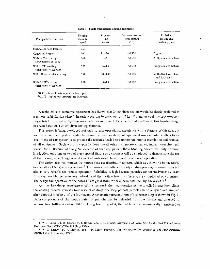
The reference recycle fuel particle design calls for four coating layers to be applied to fissile fuel kernels. Chemical vapor deposition of these coatings has recently been described by S t in t~n . ’>~ In addition, coating furnaces are required for another processing step which involves partial conversion of the feed kernels from U02 to UC2. Typical parameters for the conversion and coating steps are shown in Table 1.
*Engineering Division. ‘hnstrumentation and Controls Division. 1. A. L. Lotts and J. H. Coobs, HTGR Fuel and Fuel Cycle Technology, ORNL/TM-5501 (August 1976). 2. D. P. Stinton, W. J. Lackey, and B. A. Thiele, Influence of Process Variables on Permeability and Anisotropy of
3. D. P. Stinton and W. J. Lackey, Effect of Deposition Conditions on the Properties of Fp-olytic Silicon Carbide Biso-Coated HTGR Fuel Particles, ORNL/TM-6087 (November 1977).
Coatings for High- Temperature Gas-Cooled Reactor Fuel Particles,ORNL/TM-5 743 (October 1977).
2
Table 1. Fissile microsphere coating parameters
Nominal Process Furnace process Probable Fuel particle condition diameter time temperature coating and
( w ) (min) (" C) fluidizing gases ~ ~ ~~~~
Carbonized feed kernels 360
Converted kernels 360 15-30 2.1800
With buffer coating 460 1-4 %1500 (low-density carbon)
(high-density carbon) With ILTI' coating 530 5-15 2.1 500
With silicon carbide coating 5 90 60-1 80 2.1800
With OLTIb coating 660 5-15 %1500 (high-density carbon)
Argon
Acetylene and helium
Propylene and helium
Methyltrichlorosilane
Propylene and helium
and hydrogen
'ILTI - inner low-temperature isotropic. b~~~~ - outer low-temperature isotropic.
A technical and economic assessment has shown that 24-cm-diam coaters would be clearly preferred in a remote refabrication plant.4 In such a coating furnace, up to 3.2 kg of uranium could be processed in a single batch provided no hydrogenous materials are present. Because of that assessment, this furnace design has been based on a 24-cm diam coating chamber.
This coater is being developed not only to gain operational experience with a furnace of this size, but also to obtain the expertise needed to ensure the maintainability of equipment using remote handling tools. The intent of this system is to provide the features needed to demonstrate remote installation and removal of all equipment. Such work is typically done in-cell using manipulators, cranes, impact wrenches, and special tools. Because of the great expense of such equipment, these handling devices will only be simu- lated. Also, only one or two of every special fixture or disconnect will by employed to demonstrate the use of that device, even though several identical units would be required for an in-cell operation.
The design also incorporates the porous-plate gas distributor concept, which was shown to be successful in a smaller (13-cm) coating furnace? The porous plate offers not only coating property improvements but also is very reliable for remote operation. Reliability is high because particles cannot inadvertently drain from the crucible, yet complete unloading of the particle batch can be easily accomplished on command. The design and operation of the porous-plate gas distributor have been described by Lackey et aL5
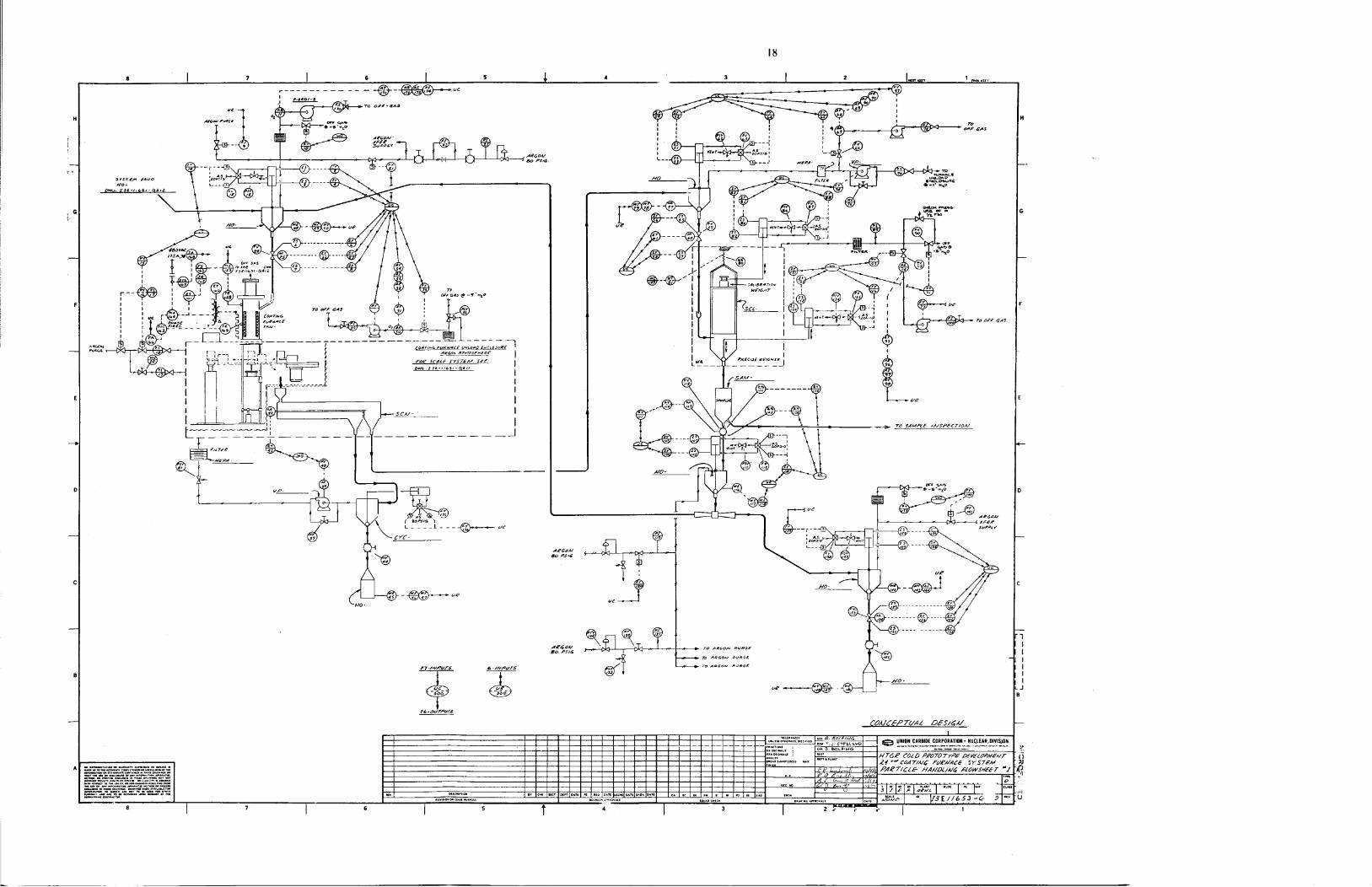
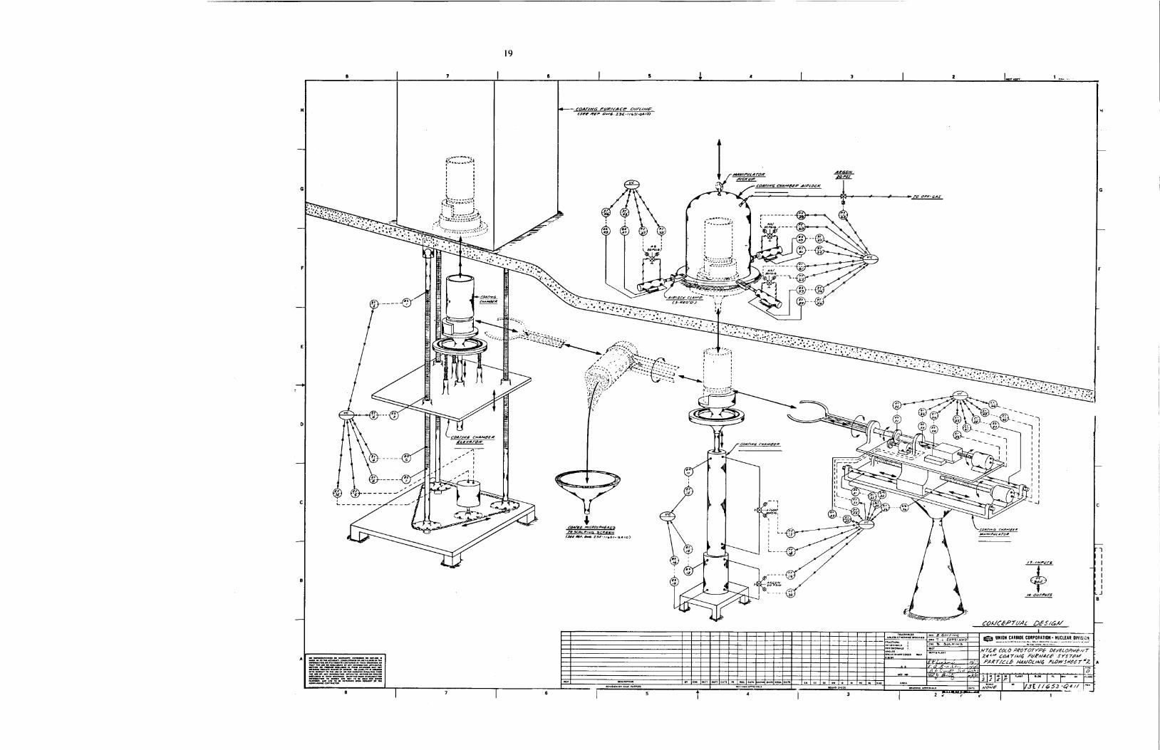
Another key design requirement of this system is the incorporation of the so-called coater loop. Since the coating process involves four distinct coatings, the loop permits particles to be weighed and sampled after deposition of any of the four layers. A schematic representation of the coater loop is shown in Fig. 1. Using components of the loop, a batch of particles can be unloaded from the furnace and screened to remove soot balls and carbon flakes. Having been upgraded, the batch can be pneumatically transferred to
.
. 4. W. J. Lackey, J. D. Jenkins, F. J. Homan, and R. S . Lowrie, Assessment of Coater Size for the Fuel Refabrication
5 . W. J. Lackey, D. P. Stinton, and J. D. Sease, Improved Gas Distributor for Coating HTGR Fuel Particles,
- Prototype Plant, ORNL/TM-4567 (July 1974).
ORNL/TM-5731 (January 1977).

ORNL-DWG 75
FROM CARBONIZATION d - f- t- - - 4- I\ - FUKNACE
tNCLOSUKt %
I-- I I I I I I I I I I I I I I I I I I I I L-
INERT -_ .- . ATMOSPHERE^^ - -.
-6967
TO POST TO COATING COATING FURNACE
Fig. 1. Coater loop schematic.
W

4
the particle inspection column, where an accurate weight and a representative sample are obtained. The batch can then be pneumatically transferred back to the furnace so that additional coating layers can be applied.
3. FURNACE SYSTEM COMPONENTS
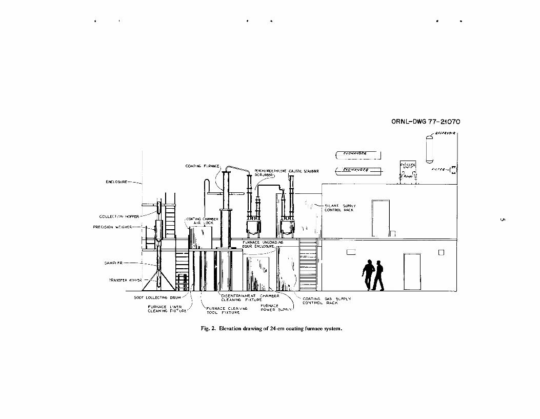
A possible layout of the coating furnace is shown in elevation and isometric drawings in Figs. 2 and 3. In addition to the furnace, the necessary support systems are also shown. These support systems include furnace loading-unloading equipment, particle weighing and sampling column, furnace cooling, furnace power supply, furnace off-gas treatment, furnace cleaning station, and coating process control and measure-
Information on each of the furnace systems is reported in this section. Conceptual design drawings for many of these systems are included in the appendix and can be referred to for better understanding of the following system components.
6 ment.
3.1 Coating Furnace
The coater is a vertically standing, fluidizing bed furnace powered by a three-phase graphite resistance heating element. The furnace is poorly insulated by intention, thus permitting rapid temperature changes and cooldown to minimize the processing cycle time. Heat loss through the furnace shell to the hot-cell atmosphere is limited by circulation of coolant fluid. The furnace has a 24-cm inside diameter, an overall height of 4.2 m, and a maximum design temperature of 2000°C.
The furnace is vertically divided into two sections, a 2.4-m lower section and a 1.8-m upper section. The lower section consists of the crucible, furnace upper liner, heating element, insulation package, and outer shell. The crucible, which forms a container for the particle batch during unloading, is assembled from a hollow graphite cylinder with a porous carbon bottom plate, through which all fluidizing and coating gases are introduced to the reaction chamber. The upper furnace liner is a second hollow graphite cylinder of the same inside diameter (24 cm) which mates with and forms an extension of the crucible.
Radially surrounding the crucible is the graphite heating element, to which a three-phase copper electrode ring will supply power. The electrode ring is cooled with a fluid coolant and is electrically insulated from the furnace outer shell, the electrode ring cover plate, and the furnace base plate. The coolant lines contain short sections of polyurethane tubing to electrically insulate the cooling piping from the electrode ring. Power will be supplied to the electrode ring by three air-cooled bus bars.
Insulation in the form of an annulus of rigidized carbon felt will separate the heating element and the outer shell, which is a double jacket of stainless steel with coolant passages between the jackets.
The upper portion of the furnace is commonly referred to as a disentrainment chamber. It adds extra height to the furnace to prevent particles which have erupted in the bed from being carried into the off-gas line. The disentrainment chamber has the same inside diameter as the crucible (24 cm) and is made of Inconel. Coolant passages are provided in the Inconel shell.
The furnace is designed for ease of remote disassembly. The disentrainment section may be opened and cleaned in place, or it may be removed to expose the lower section of the furnace. Since the heating element is very fragile, it will be mounted on the electrode ring to form a subassembly, which can be more easily handled.
3.2 Furnace Loading-Unloading Equipment
Loading of the furnace is easily accomplished by gravity feed of the particles from a charging hopper. During coating operations a valve in the feed line is closed to isolate the furnace atmosphere.
,
.
COATING F U R W
COLLECTION POP
PREC1510N WEIGHER
TRANSFER HOPPER
SILANE SUPPLY CONTROL RACh
I
COATING GAS SUPPLY CONTROL RACK > ‘DISENTRAINMENT CHAMBER
CLEANING FIXTURE 500T COLLECTING DRUM/
FURNACE FURNACE CLEAIJING POWER SUPPLY ),I TOOL FlXTURC
FURNACE LINER CLEANING F I X l U R E
Fig. 2. Elevation drawing of 24cm coating furnace system.
m

6
ORN L- DWG 77- 21 07i
Fig. 3. Isometric view of 24-cm coating furnace system.
The furnace unloading equipment is housed in a stainless steel glove-box type of enclosure, about 1.2 by 3.7 by 2.3 m high. The enclosure will contain an inert-gas atmosphere so that particles can always be safely unloaded from the furnace. This precaution is needed, since the particles are pyrophoric until at least two coatings have been applied. The enclosure also serves as a mounting base for the furnace.
One of the components in this enclosure, the elevator, is positioned directly beneath the furnace. The gas injector, which supports the coating crucible, is permanently mounted to the elevator. This permits the crucible to be vertically raised and lowered from the furnace. Made of stainless steel and OFHC (oxygen- free, high-conductivity) copper, the gas injector has passages for coating gases as well as for coolant flow.
A mechanical arm is provided to grasp the crucible when it is lowered from the furnace. The arm will have several degrees of freedom to enable it to disengage the crucible from the gas injector and to empty the particle batch by inverting the crucible. Particles fall from the crucible onto a vibratory screen, where carbon soot is removed from the batch. After the particles fall through the vibratory screen, they will be pneumatically transferred to the particle inspection column.

7
.
The furnace unloading system also has provisions for replacement of the coating crucible without disruption of the inert atmosphere in the enclosure. The manipulator arm is capable of placing a used crucible on a second elevator assembly, which then raises the crucible into a rotary magazine air lock. A new crucible is then dispensed from the magazine.
Since most of these components are located under the furnace and inside an enclosure, in-place main- tenance would be extremely difficult using hot-cell equipment. Thus, these components have been designed with the philosophy that subassemblies will be removed from the enclosure and taken to a special main- tenance area for repair. All components and subassemblies are to be designed for vertical removal in order t o simplify the use of in-cell cranes and manipulators. Motors, drives, and actuators which may need servicing have been placed outside of the enclosure where possible.
3.3 Particle Inspection Column
The inspection column equipment includes a remotely actuated precision batch weigher, a passive particle sampler, a collection hopper, a transfer hopper, and mounting fixtures. All active components are to be sealed and purged with an inert gas to prevent oxidation of pyrophoric particles. Mounting fixtures for these components have been designed for ease of remote installation and disassembly.
Particle batches will be pneumatically transferred from the furnace unloading enclosure to the collec- tion hopper on the column, from which the batch will be fed down into the weigher. There the weight of the batch will be determined with an accuracy of 0.1%; an accurate determination of the batch weight will be essential for maintaining records of material inventory. The weigher is designed to allow remote recali- bration of the weigher mechanism.
The batch will leave the weigher and fall through the sampler. The sampler, which extracts a representa- tive portion of the particles, has been described in another report.6 This device will extract 1 out of every 1024 ($4") particles to form a sample which can readily be analyzed for batch acceptance tests.
The sample will be pneumatically sent to a sample receiving station, and the remainder of the batch will drain from the sampler into the transfer hopper at the base of the column. From this hopper the batch can be sent either to a storage area or back into the furnace charging hopper if additional coating layers are to be applied.
3.4 Furnace Cooling System
The furnace cooling system is designed to use perchloroethylene or Freon-113, both of which are nonhydrogenous coolants which do not thermalize neutrons. Water, a highly moderating coolant, will not be used in this system, since the 24-cm furnace diameter is not a critically safe geometry in the presence of water. The coating furnace cooling system consists of a pipe and valving manifold, two shell and tube heat exchangers piped in parallel, two system pumps (a primary and a standby), and a coolant reservoir vessel. The system will circulate coolant through the coating furnace coolant loops and scrubber heat exchangers. The cooling system heat exchangers will be cooled by process water.
. 6 . R. R. Suchomel and W. I. Lackey, Device for Sampling HTGR Recycle Fuel Particles, ORNLITM-5739 (March
1977).

8
3.5 Furnace Power Supply
The power supply is designed as a three-phase, 480-V, 60-Hz ac inpui unit rated at 400 kVA on the basis of input voltage. The output voltage of the power supply will be Eontinuously variable from a minimum level corresponding to 15% of the maximum output power to a maximum level of approximately 30 V, 60 Hz ac. The output current level will be controlled by means of a pilot signal variable from 0 to 5 mA, transmitted to the power supply from an outside source. The output terminals of the power supply are arranged for connection to parallel copper bus bars, turned edgewise for the most effective convection cooling.
3.6 Furnace Off-Gas Treatment System
The furnace off-gas treatment system will incorporate a perchloroethylene scrubber, a sodium hydrox- ide scrubber, high-efficiency filters, and an off-gas vacuum pump. The perchloroethylene scrubber will remove carbon particulates, heat, and condensible hydrocarbons generated by the coating process. The sodium hydroxide scrubber will operate only during the silicon carbide coating step to neutralize hydro- chloric acid formed by the decomposition of the Sic coating agent, methyltrichlorosilane.
The perchloroethylene scrubber consists of a 15-cm-diam spray column and a 15-cm-diam exit gas column mounted on a 76-cm-diam surge vessel; assembled height is approximately 3.4 m. Hot gases from the coating furnace containing particulates, primarily carbon soot, will be cooled and scrubbed in the spray tower by a circulating stream of perchloroethylene. The surge vessel functions as a reservoir and gas disengaging section. The exit gas column contains an entrainment separator section of wire mesh, a gas- cooler and condenser section to reduce perchloroethylene vapor discharges in the off-gas, and a demister section of wire mesh. External to the scrubber is the circulation pump, a heat exchanger cooled by a closed loop of perchloroethylene from the furnace cooling system, the clean and dirty perchloroethylene handling system, and a packaged refrigerating unit for cooling the gas cooler and condenser with a closed inter- mediate loop of chilled perchloroethylene. The refrigerating unit is cooled with process water. The surge tank, spray tower section, entrainment separator section, and demister section are fabricated of type 304L stainless steel, all welded construction.
The sodium hydroxide scrubber consists of an ejector-venturi first-stage scrubber and a packed-column second-stage scrubber mounted on a 76-cm-diam reservoir vessel; assembled height is approximately 3.4 m. Acidic gases from the coating furnace containing hydrogen chloride, generated during the silicon carbide coating step, will be scrubbed and neutralized in the two-stage scrubber. External to the scrubber is a circulation pump distributing sodium hydroxide solution to both stages, a heat exchanger cooled by process water, and a fresh and spent scrubber solution handling system.
The off-gas vacuum pump is a positive-displacement, water-seal pump with discharge to the atmosphere passing a flame arrester.
3.7 Furnace Cleaning Station
The furnace cleaning equipment consists of a special tool with a motorized brush and a vacuum takeoff. In addition, cleaning fixtures which contain the furnace liner and disentrainment chamber during cleaning are provided. With this arrangement, the furnace components may either be brought to the fixtures for cleaning or may be cleaned in place in the furnace. A cyclone separator and soot collecting drum will collect the soot vacuumed away from the furnace parts. A similar soot collection scheme will be used to remove and store the waste carbon collected in the vibratory screen in the furnace unloading enclosure.
.
9
3.8 Coating Process Control and Measurement
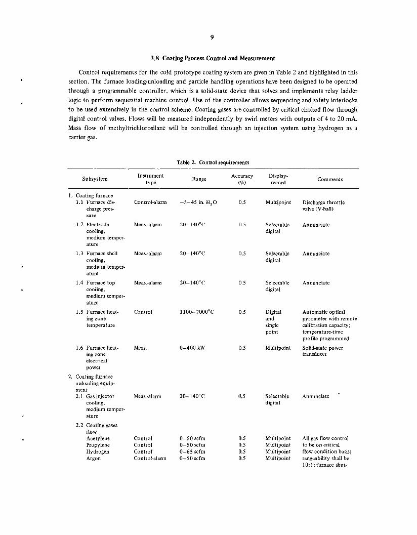
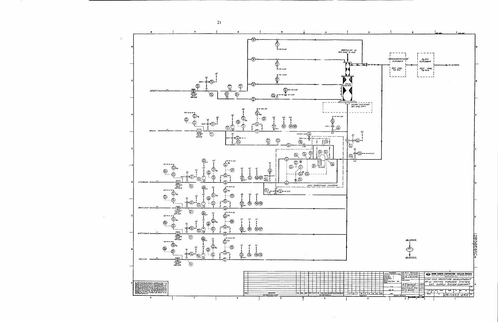
Control requirements for the cold prototype coating system are given in Table 2 and highlighted in this section. The furnace loading-unloading and particle handling operations have been designed to be operated through a programmable controller, which is a solid-state device that solves and implements relay ladder logic to perform sequential machine control. Use of the controller allows sequencing and safety interlocks to be used extensively in the control scheme. Coating gases are controlled by critical choked flow through digital control valves. Flows will be measured independently by swirl meters with outputs of 4 to 20 mA. Mass flow of methyltrichlorosilane will be controlled through an injection system using hydrogen as a carrier gas,
Table 2. Control requirements
Subsystem Instrument type
Range Accuracy Display- (%) record Comments
1. Coating furnace 1.1 Furnace dis-
charge pres- sure
1.2 Electrode cooling, medium temper- ature
1.3 Furnace shell cooling, medium temper- ature
1.4 Furnace top cooling, medium temper- ature
1.5 Furnace heat- ing zone temperature
Control-alarm
Meas.-alarm
-5-45 in. H, 0 0.5 Multipoint Discharge throttle valve (V-ball)
20-140°C 0.5 Selectable digital
Annunciate
0.5 Meas.-alarm 20-140°C Selectable digital
Annunciate
. Meas.-alarm 20- 140" C 0.5 Selectable Annunciate digital
Control 0.5 Digital Automatic optical and pyrometer with remote single calibration capacity; point temperature-time
profile programmed
Multipoint Solid-state power transducer
0-400 kW 0.5 1.6 Furnace heat- ing zone electrical power
unloading equip- ment 2.1 Gas injector
cooling, medium temper- ature
2. Coating furnace
2.2 Coating gases flow Acetylene Propylene Hydrogen Argon
Meas.
20-140°C 0.5 Selectable Annunciate digital
Meas.-alarm
Control Control Control Control-alarm
0-50 scfm 0-50 scfm 0-65 scfm 0-50 scfm
0.5 0.5 0.5 0.5
Multipoint All gas flow control Multipoint to be on critical Multipoint flow condition basis; Multipoint rangeability shall be
10: 1 ; furnace shut-

10
Table 2 (continued)
Subsystem Instrument
tY Pe Range
Accuracy Display- (%) record
Comments
Control 0-150 scfm min
0-50 scfm
AI 0-3Opsig He 0-3Opsig H, 0-2Opsig C,H, 0-15 psig C,H, 0-35 psig
0-2000 ppm
0.5 Multipoint
0.5 Multipoint
1 .o Display
down on low inert-gas flow
Methyltri- chlorosilane Helium
2.3 Coating gases supply pressures
Control-alarm
Alarm Annunciate; all gases will be regulated at the manifold rack to 15 psig
0.5 Selectable digital
2.4 Unloading enclosure oxygen concen- tration
3. Particle handling equipment 3.1 Precision
weigher
3.2 Particle transfer gas
3.3 Particle vacuum trans- fer control
4. Off-gas treatment 4.1 Off-gas
system pressure
4.2 Off-gas combustibles
Meas.-alarm
0.1 Digital of reading Digital
1 .o Meter
Interface to PLC sequence control
D/P transmitter with integral orifice
D/P transmitter with integral orifice
0-20kg ,
0-10 scfm
0-1 0 scfm
Meas.
Meas.-control
Meas. 1.0 Meter
0.5
0.5
0.5
Control-alarm
Monitor-alarm
Monitor-alarm
-4-0 psig Single point
Alarm on loss of vacuum
0-5% LEL acetylene
Meter Furnace shutdown on presence of combustibles
Furnace shutdown on high 0,
4.3 Off-gas systems oxygen con- centration
4.4 Off-gas stream temperature
5. Programmable logic controller
0-5%0, conc. Selectable digital
Type K T/C Monitor-alarm
Control
0.5
N/A
Display
N/A
Annunciate, furnace shutdown on high temperature
Control operation sequence, maintain safety interlocks, monitor alarm conditions
Inputs-outputs
The furnace temperature is measured and controlled by an infrared optical pyrometer system with an integral three-mode controller. The controller output of 0 to 5 mA is used to modulate power to the heaters through a saturable reactor system. Cooling medium and off-gas temperatures are measured with type K thermocouples and recorded on multipoint recorders. Critical temperatures will be alarmed against high or low set points.
The inert-gas enclosure under the furnace is monitored for the presence of O2 by a multichannel oxygen analyzer system. Combustible-gas analyzers continuously monitor this and other areas of the

I 1
process that could contain combustible gases. These analyzers monitor the atmosphere and will alarm if the combustible gas content exceeds 5% of the LEL (lower explosive limit).
Weights of coated rnicrosphere batches are measured by a precision weighing system utilizing a temperature-compensated strain-gage type of load cell.
Critical pressures, such as furnace pressure, exhaust system pressure, and coating gas pressures, are measured by differential pressure transmitters and monitored to alarm against high or low limits.
Critical-process variables and states are monitored continuously for alarm conditions. Monitored vari- ables will be alarmed for high and low limits. Monitored process states will be alarmed with diagnostic information indicating to the operator which process sensor or actuator has malfunctioned. Audible and visual alarms will be used. Automatic safety shutdown systems are provided to protect the process from major alarm conditions such as loss of furnace coolant, loss of power, or combustible gas leak.
The following major pieces of instrumentation are computer interfaceable for possible addition of a data acquisition system at a later date: precision weighing system, O2 analyzer system, optical pyrometer heater control system, and programmable logic controller.
4. GENERAL FABRICATION SPECIFICATIONS
With the exception of the furnace, all process equipment and transfer lines that will come in contact with the fuel particles will be fabricated from an austenitic stainless steel, typically type 304, or 304L if the vessel is a weldment.
All process vessel welds and the furnace unloading enclosure welds will be dye-checked on the root and final pass. After all welding and machining, each vessel will be leak-checked with a soap-bubble method, and the vessel’s ability to contain an overpressure for a prescribed period of time will be determined. Permissible leak rates will be in accordance with standard glove-box specifications.
The furnace graphite parts will be made from Union Carbide grade ATJ graphlte or equivalent, except the porous carbon piece for the coating crucible, which will be Union Carbide grade PC 25 carbon or equivalent.
The furnace lower shell and the electrode ring cover plate will be fabricated from type 316L stainless steel. The disentrainment chamber and furnace top plate will be fabricated from Inconel or equivalent nickel-based alloy. All coolant wetted welds not visible from the exterior of the weldment will be given a full radiographic inspection. All other coolant wetted welds will be dye-checked on each welding pass. After all welding, the coolant passages will be hydrostatically leak-checked. After all final welding and machining, these parts will be stress-relief annealed.
The furnace electrode ring segments, the bus bars, and the gas distributor will be fabricated from OFHC copper. All coolant wetted braze joints in the electrode ring and gas distributor will be given a full radiograph inspection. The bolted and pressed mating surfaces of the bus bars and the electrode ring will be silver-plated at least 25 pm thick.
All nonmetal parts, seals, etc., will be such that the functionally significant material properties will not be degraded by a cumulative beta-gamma dose of lo6 Gy.
5. PRINCIPAL SAFETY, FIRE, AND HEALTH HAZARDS
Normal operation of the coating furnace will require protection against a number of hazards as a result of large inventories of combustible gases, the presence of toxic and corrosive materials, and exposure to low-level alpha radiation from unirradiated fuels of natural or depleted uranium and thorium.

12
The design requirements for radiological and industrial safety will be implemented in strict compliance with current regulations and with the safety policies specified in applicable safety and health physics manuals.
The furnace has been designed to maintain exposure to alpha radiation as low as practical during all operations, including maintenance operations, and to avoid or minimize the potential hazards of working with alpha-emitting, toxic, or potentially explosive materials. A general summary of the hazards and the safety philosophy applied to each is given below.
The large quantities of combustible gases used in the coating process and the nature of the coating process itself involve a potential fire and explosion hazard in the event that equipment failure results in combustible gas-air mixtures or exposure of pyrophoric particles to air. Hazardous conditions could develop from leaks in the combustible gas supply system into surrounding air; air in the furnace unloading equip- ment enclosure, the coating furnace, and the furnace off-gas system; and high pressures within the furnace unloading enclosure and the furnace itself.
Proven principles of safety implemented by reliable and redundant control and detection instrumenta- tion will be applied to prevent or minimize every credible fire and explosion hazard. Combustible gases will be flow-limited at the source; ventilation will prevent gas accumulation and provide dilution below the LEL in all possible leak-rate conditions; combustible gas analyzers will monitor for leaks and trigger shutdown and purge systems; oxygen analyzers will monitor the inert-gas enclosure, the coater furnace, and the off-gas system; and at critical control points active pressure control systems will be backed up by passive, dedicated pressure relief systems. In the event of power failure, critical systems, such as furnace cooling, instrumentation, and the off-gas system, will be supplied with emergency power.
Methyltrichlorosilane is a toxic and corrosive chemical used in the deposition of silicon carbide coatings on fuel particles. The liquid will cause skin and eye burns, and the vapors will cause eye damage and lung damage, if ingested or contacted. The storage and feed system will be located in a well-ventilated, hooded area, where all chemical transfers will take place. Operating procedures will require gloves, apron, and gas mask when transferring the chemical from the shipping container to the storage vessel.
Toxic chemicals are also formed during coating operations when cracked gases recombine to form a wide variety of hydrocarbon products. These products have been shown to include polynuclear aromatic hydrocarbons; a number of these compounds are known to be carcinogenic, cocarcinogenic, and tumor promoters. Experience with existing coating furnace operations has shown that 80% of such compounds are scrubbed out of the gas stream by the perchloroethylene scrubber, and the remaining 20% are removed by high-efficiency filters in the furnace off-gas system.

13
.
ACKNOWLEDGMENTS
The authors wish to thank Millie Anderson for her help in preparing the report, which was edited and typed by Adroit, Inc. of Oak Ridge.
*U.S.GOVERNMENTPRlNTINGOFFICE:1978 -740 -190/ 49

14
APPENDIX
System Components
Material and Energy Balance Furnace and Unloading Equipment Particle Handling Column Particle Handling Flowsheet No. 1 Particle Handling Flowsheet No. 2 Cooling System Flowsheet Gas Supply Flowsheet Perchloroethylene Scrubber Flowsheet NaOH Scrubber Flowsheet Fiurnace Cleaning Fixture
Drawing Number
J3E11653-EOO2 X3E11653-AOOl X3E11653-AO02 13E11651-Q410 13E11651 Q411 13E11653-Q415 13E11653-Q412 13E 1 1653-Q413 13E11653-Q414 X3E11653-AOOS

VI
Lo
w I,
, '1
, $F la

r------
et
#e
77
07
7
W3
6
?

T I

I ."
\ -
I U
L
- -
:m r------
&
+-E-
I I
0
Y
t Y
n
U
m
...
!
b
CI
I
tp TI
t Q
21
1 uc
I 6

I
3---
t
-- -I-
s L

z
I u
Lc I
w
4 a
U
.. L
- -
r------
. L
sQ
F.
I :m
Y
E
7
,-a I
U
U
U
U

- Y
2"

ORN L/TM-6321 Dist. Category UC-77
INTERNAL DISTRIBUTION
1-2. Central Research Library 3. Document Reference Section
4-1 2. Laboratory Records Department 13. Laboratory Records, ORNL RC 14. ORNL Patent Office 15. E. J. Allen 16. R. L. Beatty
17-18. B. J. Bolfing 19-20. R. A. Bradley 21-22. R. J. Braatz
23. A. J. Caputo 24. J. A. Carpenter 25. B. F. Crump 26. F. C. Davis 27. R. G. Donnelly 28. B. C. Duggins 29. W. P. Eatherly 30. J. I. Federer
33. R. L. Heestand 34. L. C. Henley
38. J. D. Jenkins
31-32. J. L. Heck
35-37. M. R. Hill
39. D. R. Johnson 40. R. R. Judkins 41. M. J. Kania
42-51. P. R. Kasten 52. J. J. Kurtz 53. W. J. Lackey 54. A. L. Lotts 55. J. E. Mack 56. S. R. McNeany 57. J. W. Moore 58. C. S. Morgan 59. K. J. Notz 60. A. R. Olsen 6 1. R. E. Reesor 62. J. E. Selle
63-67. R. R. Suchomel 68. S. M. Tiegs 69. D. B. Trauger 70. R. G. Wymer 7 1. R. W. Balluffi (consul tan t) 72. P. M. Brister (consultant) 73. W. R. Hibbard, Jr. (consultant) 74. N. E. Promise1 (consultant)
EXTERNAL DISTRIBUTION
75-78. DOE DIVISION OF NUCLEAR POWER DEVELOPMENT, Washington, D.C. 20545 Direct or Assistant Director, Fuel Cycle Chief, Technology Branch Chief, Projects Branch
Barry Smith
Senior Program Coordinator
Director, Research and Technical Support Division Director, Reactor Division F. E. Dearing, Reactor Division
For distribution as shown in TID-4500 Distribution Category, UC-77, Gas-Cooled Reactor Technology (25 copies ~ NTIS)
79. DOE IDAHO OPERATIONS OFFICE, P.O. Box 2108, Idaho Falls, ID 83401
80. SAN-DEVELOPMENT, SAN DIEGO AREA OFFICE, P.O. Box 81325, San Diego, CA 92138
81-83. DOE OAK RIDGE OPERATIONS OFFICE, P.O. Box E, Oak Ridge, TN 37830
84-260. DOE TECHNICAL INFORMATION CENTER, P.O. Box 62, Oak Ridge, TN 37830