abb measurement & analytics | data sheet lmt200 … · 2019-04-15 · lt200 etel t etostte leel...
TRANSCRIPT
—ABB MEASUREMENT & ANALYTICS | DATA SHEET
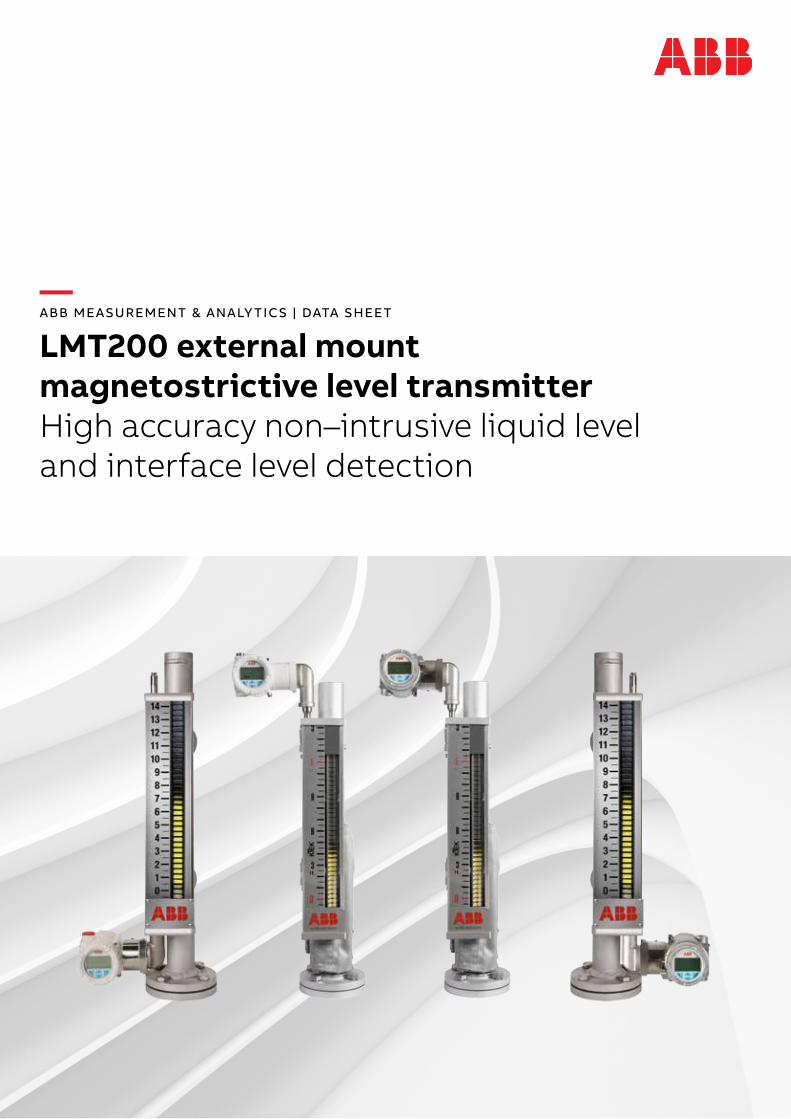
LMT200 external mount magnetostrictive level transmitterHigh accuracy non–intrusive liquid level and interface level detection

—Measurement made easy K–TEK Level products
—Features • Calibrated from the factory • High accuracy: .01 % of full scale or ±1.27 mm • No re–calibration needed: set it and forget it• Easy setup with waveform display • Not affected by agitation, foam or emulsion layers • No oscilloscope required • Designed to mount externally to K–TEK KM26 or other
magnetic level gauge • Superior sensor (patent #5,473,245) • Local indication with HMI display • Dual compartment housing with separate field terminal
compartment • Loop powered to 15.24 m (50 ft) probe length • Total and/or interface level measurement • Temperature range: –195.5 to 426.6 °C (–320 to 800 °F)
with options • Field replaceable/upgradable electronics module • Built–in RFI/EMI filter • Digital communications • Online self–verification • HART 7® and FOUNDATION Fieldbus™ ITK6.3.0• Global hazardous location approvals and SIL 2/3 capable
—Options • Two level indications • Glass viewing window • 316 stainless steel enclosure • Built–in surge protection
2 LMT200 EXTERNAL MOUNT MAGNETOSTRICTIVE LEVEL TRANSMIT TER | DS/LMT200-EN REV.C

3LMT200 EXTERNAL MOUNT MAGNETOSTRICTIVE LEVEL TRANSMIT TER | DS/LMT200-EN REV.C
—Principle of operation: The LMT200 is based upon the magnetostrictive principle. 1 The device electronics generates a low energy current
pulse at fixed intervals. 2 The electrical pulses create a magnetic field which
travels down a specialized wire inside the sensor tube. 3 The interaction of the magnetic field around the wire and
the magnetic float causes a torsional stress wave to be induced in the wire. This torsion propagates along the wire at a known velocity, from the position of the magnetic float and toward both ends of the wire.
4 A patented sensing element placed in the transmitter assembly converts the received mechanical torsion into an electrical return pulse.
5 The microprocessor–based electronics measures the elapsed time between the start and return pulses (Time of Flight) and converts it into a position measurement which is proportional to the level of the float.
Sensor
Sensor wire
Current pulse
LMT200 non–intrusive single level installation.
Top and bottom mount shown.
LMT200 non–intrusive level and interface installation.
Top and bottom mount shown.
Sensor tube
Magnetic float assembly
2
4
11
2
3
4
5
3
5

4 LMT200 EXTERNAL MOUNT MAGNETOSTRICTIVE LEVEL TRANSMIT TER | DS/LMT200-EN REV.C
Electronic transmitter
Repeatability ±0.005 % Of full scale or 0.315 mm (0.012 in), whichever is greater
Non–linearity ±0.01 % Of full scale or 0.86 mm (0.034 in), whichever is greater
Measuring accuracy ±0.01 % Of full scale or 1.27 mm (0.050 in), whichever is greater1
Supply voltage 12 to 43 V DC for 4 to 20mA HART loop powered, 9.0 to 32 V DC for Foundation™ Fieldbus
Output/Communications 4 to 20 mA HART7® or FOUNDATION Fieldbus ITK6.3.0
User interface Interactive display, DTM, EDDL with NE107 messaging
Power consumption 4 to 20 mA at 36.0 V DC – 3.6 mA 0.13 W; 21mA 0.76 W at 12.0 V DC – 3.6 mA 0.043 W; 21mA 0.25 W
HART mode (3.6 mA) at 36.0 V DC 0.144 W at 12.0 V DC 0.048 W
FF mode (17 mA) at 9.0 V DC 0.153 Wat 32.0 V DC 0.544 W
Maximum line resistance 4 to 20 mA at 36.0 V DC and 21mA, 1142 Ω*at 24.0 V DC and 21mA, 571 Ω at 13.5 V DC and 21mA, < 72 Ω** *Maximum allowable with HART communication is 700 Ω
**See the current/resistance chart
HART mode (3.6 mA) < 650 to 700 ohm
FF mode (17 mA) at 32.0 V DC, 1500 Ω.at 9.0 V DC, 50 Ω.
Polarity protection Diode in series with loop
Update rate 10 measurements per second
Minimum measuring span 76.2 mm (3.0 in) consult factory if less is required
Damping Field adjustable, range: 0.1 to 60 s
Alarm output NE43, software or hardware selectable. Upscale (21 mA) or downscale (3.6 mA)
Surge suppression Integral surge suppression available with option code S1
Ambient temperature –40 to 85°C (–40 to 185°F) ambient2
Humidity 0 to 100 % RH
Linearization 21 point table available
Enclosure Dual compartment
Enclosure material Cast low copper aluminum with powder coat or 316 stainless steel
Remote transmitter Standard remote distances of 5 m (16 ft), 10 m (33 ft), 20 m (66 ft), 30 m (98 ft)
Device tag material AISI 316 stainless steel
Electrical connection Two M20 x 1.5 or two ½ in FNPT, adapters and bus connectors also available
Ingress protection IP66, NEMA 4X
Sensor tube
Material 316/L Stainless Steel
Standard probe length 304.8mm to 15.24 m (1 to 50 ft); 90 degree probes (SEH option) 304.8 mm to 7.62 m (1 to 25 ft)
Probe length tolerance ±3.2 mm (0.125 in) up to 3.0 m (10 ft); ±6.4 mm (0.25 in) up to 6.0 m (20 ft); ±9.0 mm (0.35 in) up to 9.0 m (29.5 ft); ±25.4 mm (1.0 in) up to 15.24 m (50 ft)
Mounting Stainless steel clamps for KM26 magnetic level gauge chamber included; optional vibration isolation mounts
1 Measurementaccuracyisrecordedatfactoryambientconditions(23.88°F±5.6°C[75°F±10°F])usingacalibrationmagnet.Accuracymaybefurtherinfluencedbyotherfactorssuchasfloathysteresis,installation,processconditionsandambientconditions.
2 Someagencyapprovalsmaydiffer.
—Specifications
5LMT200 EXTERNAL MOUNT MAGNETOSTRICTIVE LEVEL TRANSMIT TER | DS/LMT200-EN REV.C
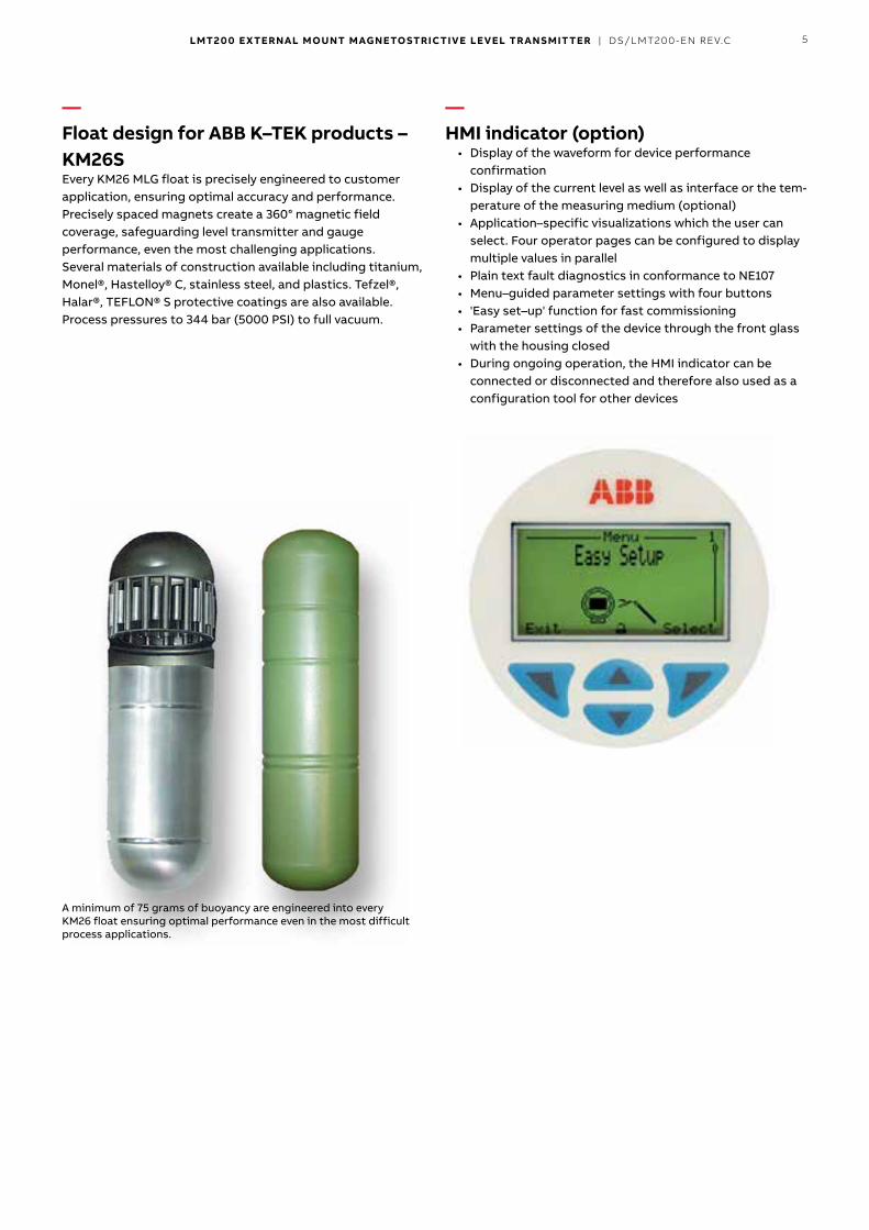
—Float design for ABB K–TEK products – KM26S Every KM26 MLG float is precisely engineered to customer applica tion, ensuring optimal accuracy and performance. Precisely spaced magnets create a 360° magnetic field coverage, safeguarding level transmitter and gauge performance, even the most challenging applications. Several materials of construction available including titanium, Monel®, Hastelloy® C, stainless steel, and plastics. Tefzel®, Halar®, TEFLON® S protective coatings are also available. Process pressures to 344 bar (5000 PSI) to full vacuum.
A minimum of 75 grams of buoyancy are engineered into every KM26 float ensuring optimal performance even in the most difficult process applications.
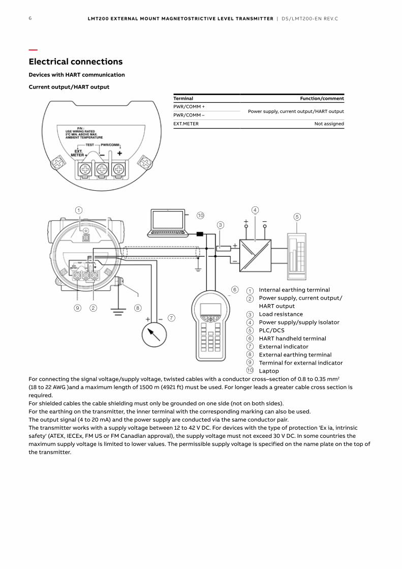
—HMI indicator (option)
• Display of the waveform for device performance confirmation
• Display of the current level as well as interface or the temperature of the measuring medium (optional)
• Application–specific visualizations which the user can select. Four operator pages can be configured to display multiple values in parallel
• Plain text fault diagnostics in conformance to NE107 • Menu–guided parameter settings with four buttons • 'Easy set–up' function for fast commissioning • Parameter settings of the device through the front glass
with the housing closed • During ongoing operation, the HMI indicator can be
connect ed or disconnected and therefore also used as a configura tion tool for other devices
6 LMT200 EXTERNAL MOUNT MAGNETOSTRICTIVE LEVEL TRANSMIT TER | DS/LMT200-EN REV.C
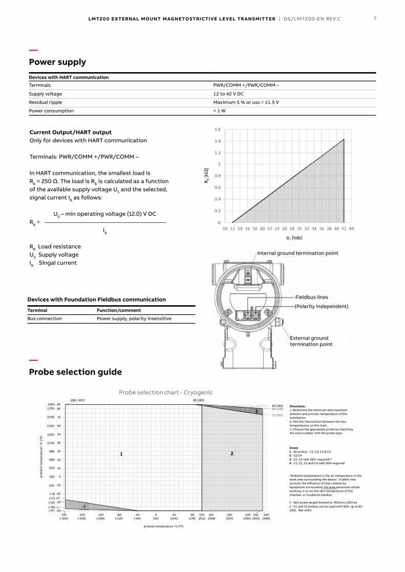
—Electrical connections Devices with HART communication
Current output/HART output
For connecting the signal voltage/supply voltage, twisted cables with a conductor cross–section of 0.8 to 0.35 mm2 (18 to 22 AWG )and a maximum length of 1500 m (4921 ft) must be used. For longer leads a greater cable cross section is required. For shielded cables the cable shielding must only be grounded on one side (not on both sides). For the earthing on the transmitter, the inner terminal with the corresponding marking can also be used. The output signal (4 to 20 mA) and the power supply are conducted via the same conductor pair. The transmitter works with a supply voltage between 12 to 42 V DC. For devices with the type of protection 'Ex ia, intrinsic safety' (ATEX, IECEx, FM US or FM Canadian approval), the supply voltage must not exceed 30 V DC. In some countries the maximum supply voltage is limited to lower values. The permissible supply voltage is specified on the name plate on the top of the transmitter.
Terminal Function/comment
PWR/COMM +Power supply, current output/HART output
PWR/COMM –
EXT.METER Not assigned
1 Internal earthing terminal 2 Power supply, current output/
HART output 3 Load resistance 4 Power supply/supply isolator 5 PLC/DCS 6 HART handheld terminal 7 External indicator 8 External earthing terminal 9 Terminal for external indicator 10 Laptop
54
3
6
7
7829
1
1 2 3 4 5 6 7 8 9 0
0
7LMT200 EXTERNAL MOUNT MAGNETOSTRICTIVE LEVEL TRANSMIT TER | DS/LMT200-EN REV.C
Current Output/HART outputOnly for devices with HART communication
Terminals: PWR/COMM +/PWR/COMM –
In HART communication, the smallest load is RB = 250 Ω. The load is RB is calculated as a function of the available supply voltage US and the selected, signal current IB as follows:
RB =
RB Load resistanceUS Supply voltageIB Singal current
US – min operating voltage (12.0) V DC
IB
Devices with HART communication
Terminals PWR/COMM +/PWR/COMM –
Supply voltage 12 to 42 V DC
Residual ripple Maximum 5 % or uss = ±1.5 V
Power consumption < 1 W
Devices with Foundation Fieldbus communication
Terminal Function/comment
Bus connection Power supply, polarity insensitive
1 - C1 & C3
-38
-27
80 (176)
73 (163)
-40
-30
-20
-10
0
10
20
30
40
50
60
70
80
-200 -160 -120 -80 -40 0 40 80 120 160 200 240
Probe selection chart - Cryogenic
85
process temperature oC (oF)
-196
(-36)
(14)
(-4)
(-22)(-17)
(32)
(104)
(86)
(68)
(50)
(176)
(158)
(140)
(122)
85 (185)
1 2
(-40)4
383 (181)
100
3
-196 (-320)
4
amb
ient
tem
per
atur
e*oC
(oF)
)054( )293( )023( )842( )671( )401( )23( )04-( )211-( )481-( )652-( )023-( (212) (464)232
(185)
Zones1 - All probes - C1, C2, C3 & C42 - C2,C43 - C2, C4 with SEH required1,2
4 - C1, C2, C3 and C4 with SEH required1
*Ambient temperature is the air temperature in thework area surrounding the device. It takes intoaccount the influence of heat created byequipment surrounding the area personnel will beworking. It is not the skin temperature of thechamber or insulation blanket.
1 - SEH probe length limited to 7620mm (300 in)2 - C1 and C2 probes can be used with SEH up to 83(181). See chart.
Directions:1. determine the minimum and maximumambient and process temperature of theinstallation.2. Plot the intersection between the twotemperatures on the chart.3. Choose the appropiate probe by matchingthe zone number with the probe type.
Fieldbus lines
Internal ground termination point
External ground termination point
(Polarity independent)
—Power supply
—Probe selection guide

8 LMT200 EXTERNAL MOUNT MAGNETOSTRICTIVE LEVEL TRANSMIT TER | DS/LMT200-EN REV.C
—Approvals Flameproof marking
• ATEX/IECEx – II ½ G Ex db IIC T6..T2 Ga/Gb – FM15ATEX0074X – IECEx FME 17.0004X – Power supply 42 V DC/2 W max.
• FM (C and US) approved – CLI zone 1, AEx/Ex db IIC T6 to T2 Gb – US – CLI GP ABCD, T6 to T2 – Canada – CLI GP BCD, T6 to T2
Protection by enclosure marking • ATEX/IECEx
– II 2 D Ex tb IIIC T85 °C to T300 °C Db FM15ATEX0074X – IECEx FME17.0004X power supply 42 V DC/2W max.
• FM (C and US) approved – Zone 21 AEx/Ex tb IIIC T80 °C to T165 °C Db – US – CLII GP EFG, CLIII T6 to T2 – Canada – CLII GP EFG, CLIII T6 to T2
Intrinsic/non–incendive marking• ATEX/IECEx
II 1 G Ex ia IIC T6toT4 GaII 1 D Ex ia IIIC T80 °C Da;FISCO field device, FF–816 for (PA/FF output)FM17ATEX0062X – IECEx FME17.0004XII 3 G Ex ic IIC T6..T4 GcII 3 D Ex ic IIIC T80 °C DcFISCO field device, FF–816 for (PA/FF output)II 3 G Ex nA IIC T6..T4 GcFM17ATEX0063X – IECEx FME17.0004X
• FM (C and US) approvedCLI DIV1/GP ABCD, CLII/DIV1/GP EFG, CLIII;CLI ZONE 0 AEx/Ex ia IIC T6 to T4 Ga;Zone 20 AEx ia IIIC T80 °C; CLII/III DIV1 Ex ia IIIC T80 °C;CLI/DIV2/GP ABCD; CLII/DIV2/GP FG; CLIII;CLI ZONE 2, AEx nC IIC T6 to T4;CLI ZONE 2, Ex nL IIC T6 to T4;FISCO field device, FF–816 for (PA/FF output)per 3KXL140000G0109
1 - C1 & C3
80 (176)83 (181)
58 (136)
85 (185)
-36, (-33)
-40
-30
-20
-10
0
10
20
30
40
50
60
70
80
-80 -40 0 40 80 120 160 200 240 280 320 360 400
Probe selection chart - standard
1 2
85
process temperature oC (oF)
73 (163)
(-40)
(14)
(-4)
(-22)
(32)
(104)
(86)
(68)
(50)
(176)
(158)
(140)
(122)
43
232 (450)
427
-80 (-112)
0
2
amb
ient
tem
per
atur
e*o C
(o F)
(-112) (-76) (-4) (32) (68) (140) (212) (284) (356) (428) (500) (572) (644) (716) (800)
232(450)
(185)
Zones1 - R1 & R2 probes2 - R2 probe3 - R1 & R2 with SEH required1
4 - R2 with SEH required1
*Ambient temperature is the air temperature inthe work area surrounding the device. It takesinto account the influence of heat created byequipment surrounding the area personnel will beworking. It is not the skin temperature of thechamber or insulation blanket.
1 - SEH probe length limited to 7620mm (300 in)
Directions:1. determine the maximum ambienttempearture and the maximum processtemperature of the installation.2. Plot the intersection between the twotemperatures on the chart.3. Choose the appropiate probe by matchingthe zone number with the probe type.
—...Probe selection guide
9LMT200 EXTERNAL MOUNT MAGNETOSTRICTIVE LEVEL TRANSMIT TER | DS/LMT200-EN REV.C
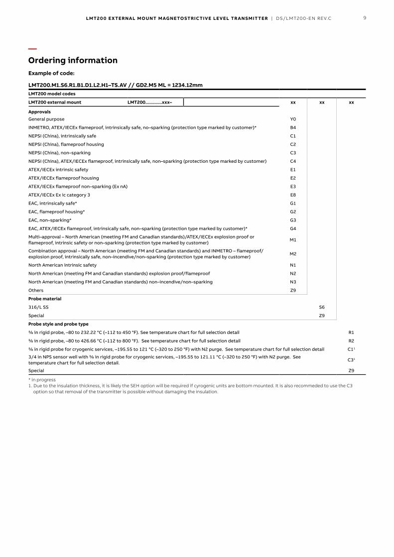
Example of code:
LMT200.M1.S6.R1.B1.D1.L2.H1–TS.AV // GD2.M5 ML = 1234.12mm LMT200 model codes
LMT200 external mount LMT200.............xxx– xx xx xx
ApprovalsGeneral purpose Y0
INMETRO, ATEX/IECEx flameproof, intrinsically safe, no–sparking (protection type marked by customer)* B4
NEPSI (China), intrinsically safe C1
NEPSI (China), flameproof housing C2
NEPSI (China), non–sparking C3
NEPSI (China), ATEX/IECEx flameproof, intrinsically safe, non–sparking (protection type marked by customer) C4
ATEX/IECEx intrinsic safety E1
ATEX/IECEx flameproof housing E2
ATEX/IECEx flameproof non–sparking (Ex nA) E3
ATEX/IECEx Ex ic category 3 E8
EAC, intrinsically safe* G1
EAC, flameproof housing* G2
EAC, non–sparking* G3
EAC, ATEX/IECEx flameproof, intrinsically safe, non–sparking (protection type marked by customer)* G4
Multi–approval – North American (meeting FM and Canadian standards)/ATEX/IECEx explosion proof or flameproof, intrinsic safety or non–sparking (protection type marked by customer)
M1
Combination approval – North American (meeting FM and Canadian standards) and INMETRO – flameproof/explosion proof, intrinsically safe, non–incendive/non–sparking (protection type marked by customer)
M2
North American intrinsic safety N1
North American (meeting FM and Canadian standards) explosion proof/flameproof N2
North American (meeting FM and Canadian standards) non–incendive/non–sparking N3
Others Z9
Probe material
316/L SS S6
Special Z9
Probe style and probe type
⅝ in rigid probe, –80 to 232.22 °C (–112 to 450 °F). See temperature chart for full selection detail R1
⅝ in rigid probe, –80 to 426.66 °C (–112 to 800 °F). See temperature chart for full selection detail R2
⅝ in rigid probe for cryogenic services, –195.55 to 121 °C (–320 to 250 °F) with N2 purge. See temperature chart for full selection detail C11
3/4 in NPS sensor well with ⅝ in rigid probe for cryogenic services, –195.55 to 121.11 °C (–320 to 250 °F) with N2 purge. See temperature chart for full selection detail.
C31
Special Z9
* in progress1.Duetotheinsulationthickness,itislikelytheSEHoptionwillberequiredifcyrogenicunitsarebottommounted.ItisalsorecommededtousetheC3optionsothatremovalofthetransmitterispossiblewithoutdamagingtheinsulation.
—Ordering information
10 LMT200 EXTERNAL MOUNT MAGNETOSTRICTIVE LEVEL TRANSMIT TER | DS/LMT200-EN REV.C
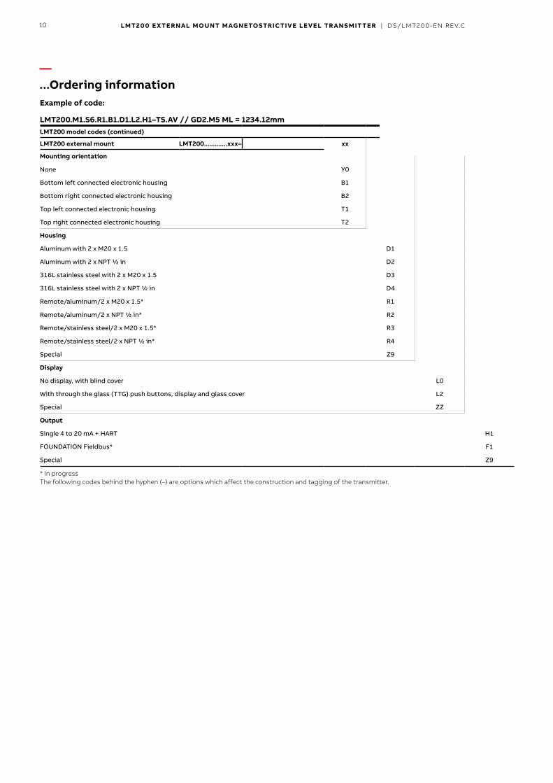
Example of code:
LMT200.M1.S6.R1.B1.D1.L2.H1–TS.AV // GD2.M5 ML = 1234.12mm LMT200 model codes (continued)
LMT200 external mount LMT200.............xxx– xx xx xx xx
Mounting orientation
None Y0
Bottom left connected electronic housing B1
Bottom right connected electronic housing B2
Top left connected electronic housing T1
Top right connected electronic housing T2
Housing
Aluminum with 2 x M20 x 1.5 D1
Aluminum with 2 x NPT ½ in D2
316L stainless steel with 2 x M20 x 1.5 D3
316L stainless steel with 2 x NPT ½ in D4
Remote/aluminum/2 x M20 x 1.5* R1
Remote/aluminum/2 x NPT ½ in* R2
Remote/stainless steel/2 x M20 x 1.5* R3
Remote/stainless steel/2 x NPT ½ in* R4
Special Z9
Display
No display, with blind cover L0
With through the glass (TTG) push buttons, display and glass cover L2
Special ZZ
Output
Single 4 to 20 mA + HART H1
FOUNDATION Fieldbus* F1
Special Z9
* in progressThefollowingcodesbehindthehyphen(–)areoptionswhichaffecttheconstructionandtaggingofthetransmitter.
—...Ordering information

11LMT200 EXTERNAL MOUNT MAGNETOSTRICTIVE LEVEL TRANSMIT TER | DS/LMT200-EN REV.C
Example of code:
LMT200.M1.S6.R1.B1.D1.L2.H1–TS.AV // GD2.M5 ML = 1234.12mm
The following codes behind the hyphen (–) are options which affect the construction and tagging of the transmitter. Options
LMT200.............xxx–xxx.xx xx xxx xx xxx xx xx(x) xx
SIL certification
SIL2 (HFT=0) and SIL3 (HFT=1) – certified acc. to IEC61508 CS
Sensor probe options
90 degree bend housing extension (maximum probe length 7.62 m/25 ft) SEH
Add nitrogen purged vapor seal to standard probe SEV1
Sensor special SEZ
Device identification plate
Add stainless steel hang tag, custom markings 4 lines, 22 characters per line TS
Other tagging special TZ
Signal cable length (for remote transmitter only)
5 m (approx. 16 ft)* SC1
10 m (approx. 33 ft)* SC2
20 m (approx. 66 ft)* SC4
30 m (approx. 98 ft)* SC6
Surge protector
Surge/transient protector S1
Special other
Special paint or treatment on housing STH
Nuclear use, device to be used in a nuclear facility (application must be reviewed by ABB) P4
Special PZ
Mounted accessories
Mounted to chamber with vibration isolators, minimum 2 assemblies and additional assemblies per additional 5 ft of probe length AV
Valve position transmitter kit including mounting bracket and magnet assembly (in progress, contact factory) AT
* in progress1.SEVoptionisforR1,R2sensors.C1,C3includevaporseals.
All codes located behind the // are for additional requirements and order comments.
These codes will not be included on the device tag.
—...Ordering information
12 LMT200 EXTERNAL MOUNT MAGNETOSTRICTIVE LEVEL TRANSMIT TER | DS/LMT200-EN REV.C
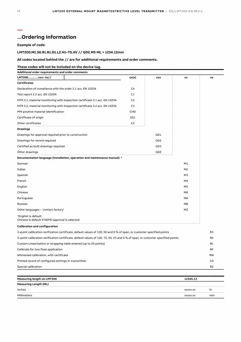
Example of code:
LMT200.M1.S6.R1.B1.D1.L2.H1–TS.AV // GD2.M5 ML = 1234.12mm
All codes located behind the // are for additional requirements and order comments.
These codes will not be included on the device tag. Additional order requirements and order comments
LMT200.............xxx– to// xx(x) xxx xx xx
Certificates
Declaration of compliance with the order 2.1 acc. EN 10204 C4
Test report 2.2 acc. EN 10204 C1
MTR 3.1, material monitoring with inspection certificate 3.1 acc. EN 10204 C2
MTR 3.2, material monitoring with inspection certificate 3.2 acc. EN 10204 C3
PMI positive material identification CHD
Certificate of origin GS1
Other certificates CZ
Drawings
Drawings for approval required prior to construction GD1
Drawings for record required GD2
Certified as built drawings required GD3
Other drawings GDZ
Documentation language (installation, operation and maintenance manual) *
German M1
Italian M2
Spanish M3
French M4
English M5
Chinese M6
Portuguese MA
Russian MB
Other languages – 'contact factory' MZ
*English is default. Chinese is default if NEPSI approval is selected
Calibration and configuration
3–point calibration verification certificate, default values of 100, 50 and 0 % of span, or customer specified points R3
5–point calibration verification certificate, default values of 100, 75, 50, 25 and 0 % of span, or customer specified points R5
Custom Linearization or strapping table entered (up to 20 points) RL
Calibrate for two float application RF
Witnessed calibration, with certificate RW
Printed record of configured settings in transmitter CG
Special calibration RZ
Measuring length on LMT200 12345.12
Measuring Length (ML)
Inches xxxxx.xx in
Millimeters xxxxx.xx mm
—...Ordering information
13LMT200 EXTERNAL MOUNT MAGNETOSTRICTIVE LEVEL TRANSMIT TER | DS/LMT200-EN REV.C
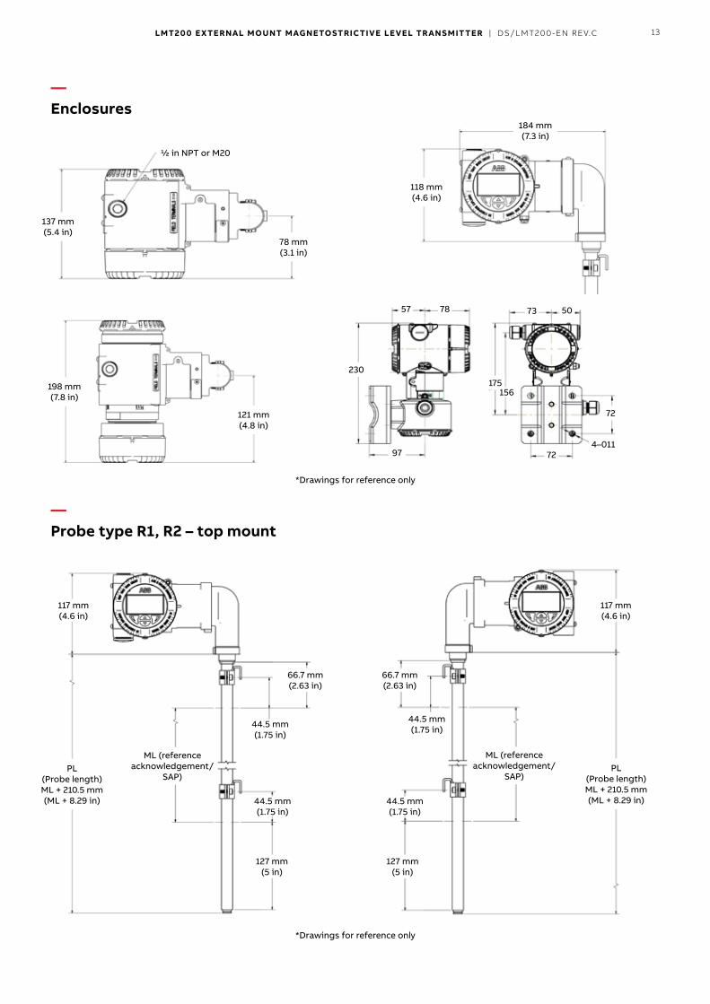
—Enclosures
*Drawings for reference only
—Probe type R1, R2 – top mount
*Drawings for reference only
PL (Probe length)ML + 210.5 mm (ML + 8.29 in)
ML (reference acknowledgement/
SAP)
ML (reference acknowledgement/
SAP)PL
(Probe length)ML + 210.5 mm (ML + 8.29 in)
117 mm (4.6 in)
117 mm (4.6 in)
44.5 mm (1.75 in)
44.5 mm (1.75 in)
44.5 mm (1.75 in)
44.5 mm (1.75 in)
127 mm (5 in)
127 mm (5 in)
66.7 mm (2.63 in)
66.7 mm (2.63 in)
57
230
97 72
72
4–011
175156
78 73 50
118 mm (4.6 in)
184 mm (7.3 in)
137 mm (5.4 in)
198 mm (7.8 in)
½ in NPT or M20
121 mm (4.8 in)
78 mm (3.1 in)
14 LMT200 EXTERNAL MOUNT MAGNETOSTRICTIVE LEVEL TRANSMIT TER | DS/LMT200-EN REV.C
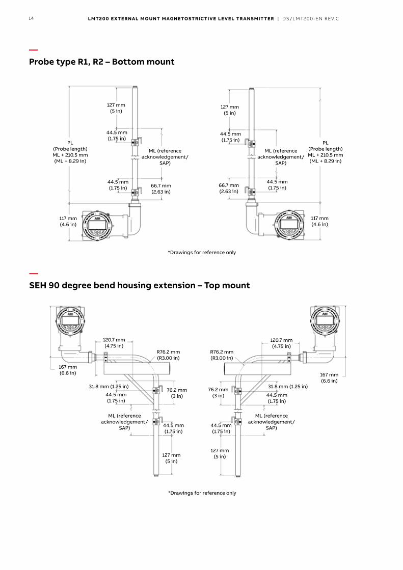
—Probe type R1, R2 – Bottom mount
*Drawings for reference only
—SEH 90 degree bend housing extension – Top mount
*Drawings for reference only
PL (Probe length)ML + 210.5 mm (ML + 8.29 in)
PL (Probe length)ML + 210.5 mm (ML + 8.29 in)
117 mm (4.6 in)
117 mm (4.6 in)
ML (reference acknowledgement/
SAP)
ML (reference acknowledgement/
SAP)
44.5 mm (1.75 in)
44.5 mm (1.75 in)
44.5 mm (1.75 in)
44.5 mm (1.75 in)
44.5 mm (1.75 in)
167 mm (6.6 in)
167 mm (6.6 in)
120.7 mm (4.75 in)
120.7 mm (4.75 in)
127 mm (5 in)
127 mm (5 in)
R76.2 mm (R3.00 in)
R76.2 mm (R3.00 in)
76.2 mm (3 in)
76.2 mm (3 in)
31.8 mm (1.25 in)31.8 mm (1.25 in)
44.5 mm (1.75 in)
44.5 mm (1.75 in)
44.5 mm (1.75 in)
127 mm (5 in)
127 mm (5 in)
66.7 mm (2.63 in)
66.7 mm (2.63 in)
ML (reference acknowledgement/
SAP)
ML (reference acknowledgement/
SAP)
15LMT200 EXTERNAL MOUNT MAGNETOSTRICTIVE LEVEL TRANSMIT TER | DS/LMT200-EN REV.C
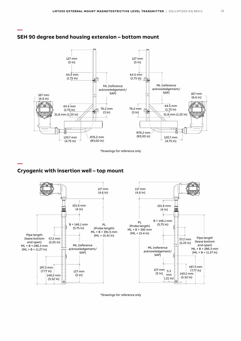
—SEH 90 degree bend housing extension – bottom mount
*Drawings for reference only
—Cryogenic with insertion well – top mount
*Drawings for reference only
ML (reference acknowledgement/
SAP)
ML (reference acknowledgement/
SAP)
44.5 mm (1.75 in)
44.5 mm (1.75 in)
44.5 mm (1.75 in)
44.5 mm (1.75 in)
101.6 mm (4 in)
101.6 mm (4 in)
117 mm (4.6 in)
117 mm (4.6 in)
167 mm (6.6 in)
167 mm (6.6 in)
120.7 mm (4.75 in)
120.7 mm (4.75 in)
127 mm (5 in)
5.3 mm
(.21 in)
B + 146.1 mm (5.75 in)
B + 146.1 mm (5.75 in)
197.3 mm (7.77 in)
197.3 mm (7.77 in)
140.2 mm (5.52 in)
140.2 mm (5.52 in)
R76.2 mm (R3.00 in)
R76.2 mm (R3.00 in)
76.2 mm (3 in)
76.2 mm (3 in)
31.8 mm (1.25 in) 31.8 mm (1.25 in)
127 mm (5 in)
127 mm (5 in)
ML (reference acknowledgement/
SAP)
ML (reference acknowledgement/
SAP)
PL (Probe length)
ML + B + 391.5 mm (ML + 15.41 in)
PL (Probe length)
ML + B + 392 mm (ML + 15.4 in)Pipe length
(leave bottom end open)
ML + B + 286.3 mm (ML + B + 11.27 in)
Pipe length (leave bottom
end open) ML + B + 286.3 mm (ML + B + 11.27 in)
57.2 mm (2.25 in)
57.2 mm (2.25 in)
127 mm (5 in)

16 LMT200 EXTERNAL MOUNT MAGNETOSTRICTIVE LEVEL TRANSMIT TER | DS/LMT200-EN REV.C
—Vibration isolator mount option
—Position transmitter mounting option
Kit includes: 1 Vibration isolator1 Chamber mounting clamp assembly2 Bearing clamp assemblies
For measurement lengths (ML) of 914.4 mm (36 in) or less, a minimum of two VI–KIT assemblies are recommended for installation in high vibration applications.For ML greater than 914.4 mm (36 in), the number of isolators required can be determined from the below chart.
ML up to # of kits
914.4 mm (36 in) 2
1828.8 mm (72 in) 3
2286.0 mm (90 in) 4
2743.2 mm (108 in) 4
3200.4 mm (126 in) 5
3657.6 mm (144 in) 5
4114.8 mm (162 in) 6
4572.0 mm (180 in) 6
> 4572.0 mm (180 in) consult factory
Close-up of Magnet Assembly
Valve
Transmitter
Actuator
MagnetAssembly
Example Installation: LMT200 Valve Position Transmitter and Hydraulic Control Valve
ValveStem
Bracket
Magnet
Mounting Brackets
Example installation: LMT200 valve position transmitter and hydraulic control valve
Close up of magnet assembly
Magnet assembly
Actuator
Transmitter
Magnet
Valve stem bracket
Valve Mounting brackets
Acknowledgements• HART is a registered trademark of the FieldComm Group.• FIELDBUS FOUNDATION™ and FOUNDATION are registered
trademarks of the Fieldbus Foundation.• Tefzel® is a registered trademark of DuPont.• Hastelloy® is a registered trademark of Haynes International, Inc.• Monel® is a registered trademark of the INCO.

—Notes
17LMT200 EXTERNAL MOUNT MAGNETOSTRICTIVE LEVEL TRANSMIT TER | DS/LMT200-EN REV.C

—Notes
18 LMT200 EXTERNAL MOUNT MAGNETOSTRICTIVE LEVEL TRANSMIT TER | DS/LMT200-EN REV.C

19LMT200 EXTERNAL MOUNT MAGNETOSTRICTIVE LEVEL TRANSMIT TER | DS/LMT200-EN REV.C

DS/LMT200–ENRev.C8.2018
—ABB Inc.IndustrialAutomation125E.CountyLineRoadWarminster,PA18974USATel: +1 215 674 6000Fax:+12156747183
ABB Engineering (Shanghai) Ltd.No.4528,KangXinHwy.PudongNewDistrictShanghai,201319,P.R.ChinaPhone:+861064231407Service:+864008209696Email:sales–[email protected]:[email protected]
www.abb.com/level
NoteWereservetherighttomaketechnicalchangesormodifythecontentsofthisdocumentwithoutpriornotice.Withregardtopurchaseorders,theagreedparticularsshallprevail.ABBdoesnotacceptanyresponsibilitywhatsoeverforpotentialerrorsorpossiblelackofinformationinthisdocument.
We reserve all rights in this document and in the subject matter and illustrationscontained therein Any reproduction, disclosure to third parties or utilization of itscontents–inwholeorinparts–isforbiddenwithoutpriorwrittenconsentofABB.
Copyright©2018ABBAllrightsreserved 3KXL141100R1001
Sales Service