a review on membranes and catalysts for anion exchange …. cho_et... · 2019-08-19 · imentally...
TRANSCRIPT
J. Electrochem. Sci. Technol., 2017, 8(3), 183-196
− 183 −
A Review on Membranes and Catalysts for Anion Exchange
Membrane Water Electrolysis Single Cells
Min Kyung Cho1, Ahyoun Lim1,2, So Young Lee1, Hyoung-Juhn Kim1,3, Sung Jong Yoo1,3,Yung-Eun Sung2,5, Hyun S. Park1,**, and Jong Hyun Jang1,3,4,*1Fuel Cell Research Center, Korea Institute of Science and Technology (KIST), Seoul 02792, Republic of Korea2School of Chemical and Biological Engineering, Seoul National University, Seoul 08826, Republic of Korea3Division of Energy & Environment Technology, KIST School, Korea University of Science and Technology, Seoul 02792,
Republic of Korea4Green School, Korea University, Seoul 02841, Republic of Korea5Center for Nanoparticle Research, Institute for Basic Science (IBS), Seoul 08826, Republic of Korea
ABSTRACT
The research efforts directed at advancing water electrolysis technology continue to intensify together with the increasing
interest in hydrogen as an alternative source of energy to fossil fuels. Among the various water electrolysis systems reported
to date, systems employing a solid polymer electrolyte membrane are known to display both improved safety and efficiency
as a result of enhanced separation of products: hydrogen and oxygen. Conducting water electrolysis in an alkaline medium
lowers the system cost by allowing non-platinum group metals to be used as catalysts for the complex multi-electron trans-
fer reactions involved in water electrolysis, namely the hydrogen and oxygen evolution reactions (HER and OER, respec-
tively). We briefly review the anion exchange membranes (AEMs) and electrocatalysts developed and applied thus far in
alkaline AEM water electrolysis (AEMWE) devices. Testing the developed components in AEMWE cells is a key step in
maximizing the device performance since cell performance depends strongly on the structure of the electrodes containing
the HER and OER catalysts and the polymer membrane under specific cell operating conditions. In this review, we discuss
the properties of reported AEMs that have been used to fabricate membrane-electrode assemblies for AEMWE cells,
including membranes based on polysulfone, poly(2,6-dimethyl-p-phylene) oxide, polybenzimidazole, and inorganic com-
posite materials. The activities and stabilities of tertiary metal oxides, metal carbon composites, and ultra-low Pt-loading
electrodes toward OER and HER in AEMWE cells are also described.
Keywords : Water electrolysis, Anion exchange membrane, Electrocatalyst, Membrane electrode assembly, Single cell
Received : 25 May 2017, Accepted : 5 July 2017
1. Introduction
Greenhouse gas (GHG) emissions arising from
fossil fuel combustion present a serious problem that
is having an increasing and unprecedented impact on
the global environment [1]. Together with the accu-
mulation of carbon dioxide in the atmosphere, GHG
emissions are the main cause of global warming and
climate change [2]. The atmospheric levels of carbon
dioxide have exceeded 400 ppm as of February 2017
and are expected to reach approximately 530 ppm by
2050 [3]. As a consequence of the increased GHG
accumulation in the atmosphere, the global aver‘age
temperature is estimated to increase by more than
3oC by 2050, which will cause unavoidable climate
change and have considerable economic and social
impacts [4]. In order to mitigate the effects of fossil
fuel consumption and GHG emissions, research
aimed at developing technologies that utilize alterna-
tive and carbon-free energy resources has been rap-
idly intensifying for the last few decades [5].
*E-mail address: *[email protected], **[email protected]
DOI: https://doi.org/10.5229/JECST.2017.8.3.183
Mini-Review
Journal of Electrochemical Science and Technology
184 Min Kyung Cho et al. / J. Electrochem. Sci. Technol., 2017, 8(3), 183-196
As the most abundant energy carrier in the uni-
verse, hydrogen is considered to be a promising
replacement for fossil fuels as a result of its non-tox-
icity, high mass energy density (39.4 kWh kg−1) [6],
and high energy efficiency (>70%) [7]. However, the
majority of hydrogen produced commercially, i.e.,
more than 40 million metric tons per year, is cur-
rently produced from industrial steam reforming pro-
cesses [8]. Hydrogen production using natural gases
still emits a significant amount of CO2 (more than
300 million tons each year), which makes it difficult
to employ this process as a sustainable hydrogen pro-
duction technology [9]. Many other technologies
have been investigated to date in an attempt to realize
carbon-free production of hydrogen on an industrial
scale such as thermolysis, photocatalysis, biomass
gasification, and electrolysis [10].
Among the various hydrogen production methods,
electrochemical water splitting employing renewable
power sources is considered as a particularly feasible
technology for the production of hydrogen without
GHG emissions [7]. Nicholson and Carlisle first
reported the water splitting phenomenon in 1800 and
it has since been actively developed for industrial
hydrogen production [11]. In this technology, a con-
ventional electrolyzer uses a porous diaphragm that
separates the anode and cathode in an alkaline solu-
tion [7,12]. The glass diaphragm conducts ions whilst
also separating the produced hydrogen and oxygen
into different chambers. Water electrolyzers based on
liquid electrolytes are already being used commer-
cially to produce highly purified and pressurized
hydrogen [13]. Recent research on electrolyzer tech-
nology, however, has been focused on developing a
system based on a solid polymer electrolyte mem-
brane, in line with the advancements achieved in the
field of polymer electrolyte membranes [13]. An
electrolyzer based on a solid polymer electrolyte
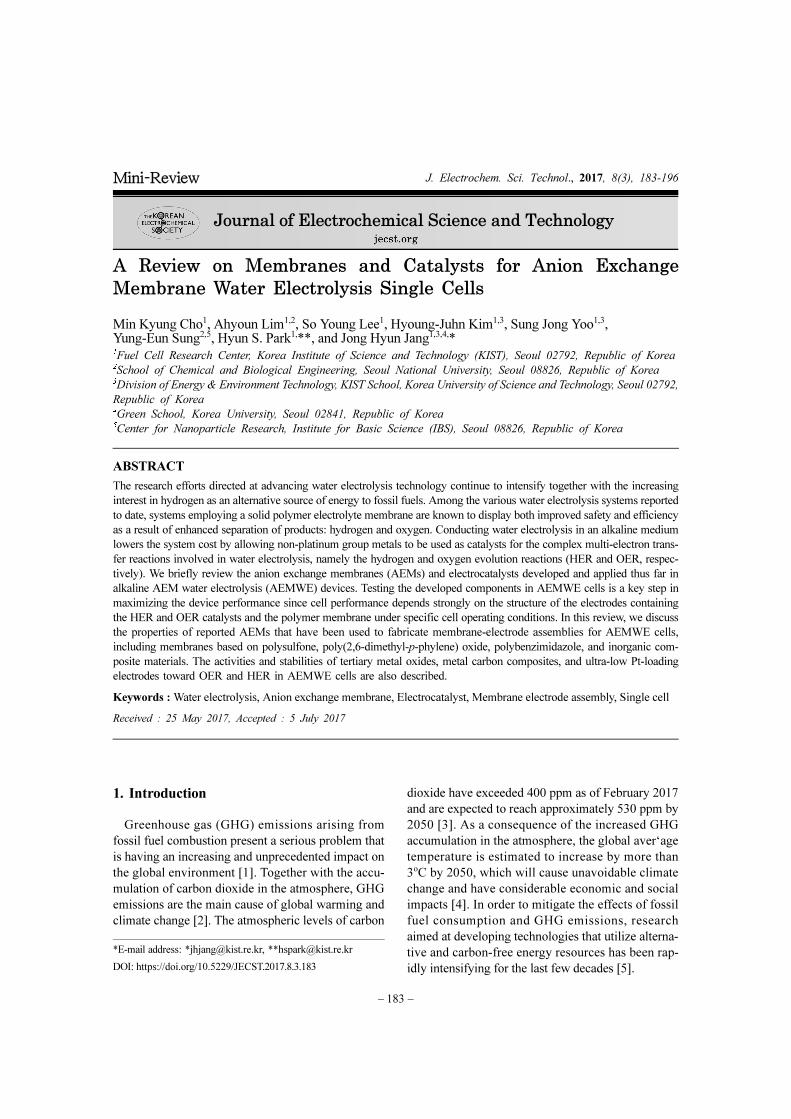
membrane consists of a membrane electrode assem-
bly (MEA), with electrodes located on both sides of
the electrolyte membrane, as illustrated in Fig. 1.
Polymer electrolyte membrane water electrolysis
provides several advantages when compared to the
use of the porous diaphragm electrolyzer, including
improved operational efficiency and safety and fac-
ile gas separation [14].
Polymer electrolyte membrane based electrolysis
systems are classified into proton exchange mem-
brane water electrolysis (PEMWE) and anion
exchange membrane water electrolysis (AEMWE)
depending on the types of ions conducted through the
polymer membrane. PEMWE exhibits greater hydro-
gen production energy efficiency compared to
AEMWE owing to the high conductivity of the
employed electrolyte membrane [15]. However,
PEMWE requires the use of expensive noble cata-
lysts such as iridium and ruthenium oxides in order to
facilitate the catalysis of the oxygen evolution reac-
tion (OER) in corrosive acid electrolytes [16]. By
contrast, performing water electrolysis under alkaline
conditions allows non-noble metal oxides such as
cobalt and nickel derivatives to be used as the water
oxidation catalyst as a result of their favorable OER
activities in basic solutions. This possibility rep-
resents a great advantage of AEMWE relative to
PEMWE and can significantly reduce the associated
costs [12,17]. It should be noted that as of March
2017, the material costs of cobalt ($0.05/g) and
Fig. 1. A schematic illustration of an AEMWE cell and a membrane electrode assembly.
Min Kyung Cho et al. / J. Electrochem. Sci. Technol., 2017, 8(3), 183-196 185
nickel ($0.01/g) [18] are significantly lower than
those of Ir ($24/g) and Ru ($1.3/g) [18]. However,
the highest operational current density reported for
AEMWE at 50oC using IrO2 as the OER catalyst
(approximately 0.5 A cm−2 at 1.8 V) [19] is consider-
ably lower than that reported for PEMWE at 50oC
using IrO2 as the OER catalyst (0.9 A cm−2 at 1.8 V)
[20]. It is clear, therefore, that there remains a signifi-
cant room for improvement in the performance of
AEMWE [21] in order to achieve operational current
density comparable with PEMWE.
In order to improve the cell performance of
AEMWE, anion exchange membranes (AEMs) with
higher conductivity and water electrolysis catalysts
with higher activity must be employed in the MEA
and the cell operating conditions must be optimized.
AEM development [21-50] has focused on con-
trolling the membrane morphology and functional-
ization with various cationic groups in an attempt to
attain excellent thermal and mechanical properties
along with improved hydroxide conductivity (≥0.1
S cm−1) [51]. Most of the developed AEMs were
employed in fuel cell applications [25,26,30,32,
35,40,42-45,47], with only a few AEMs used in
water electrolysis cell tests [21,50]. The AEMs used
in fuel-cell applications can also be used in water
electrolysis applications. However, the perfor-
mance of such AEMs should be confirmed in a
water electrolysis configuration since the cell per-
formance is highly dependent on the cell operating
conditions. OER [52-62] and hydrogen evolution
reaction (HER) [56,57,63-74] catalysts have also
been developed actively for alkaline water electrol-
ysis with the aim of achieving high catalytic activity
and chemical stability under alkaline conditions.
These developments have focused predominantly
on controlling the crystalline structure and morphol-
ogy of the catalysts and testing various transition
metals or their oxides [75]. However, only a few of
the developed catalysts have been tested in a full
cell configuration [52,63]. The full cell test is essen-
tial because the promising properties and perfor-
mances of newly developed materials must be
confirmed in an MEA configuration for single cell
performance validation. Therefore, along with
enhancing the system components, optimizing the
MEA configuration is also of significant importance
in order to fully utilize the functionality of the cell
components [76].
MEAs for AEMWE are composed of anion con-
ducting polymer electrolyte membranes, with cata-
lyst layers and diffusion layers located on both sides
of the membrane. Hydroxide ions are produced by
the HER at the cathode, subsequently transported
from the cathode to the anode through the membrane,
and finally oxidized into oxygen gas, water, and elec-
trons [19]. To obtain high performance AEMWE,
MEA optimization should be performed in tandem
with material development so as to achieve facile
electrochemical reactions. For example, extensive
research has been conducted to optimize the MEA
performance in PEM fuel cells, with many variables
investigated such as the ionomer content in the cata-
lyst layer [77-80], the catalyst layer structure [81-83],
and the pressing conditions in the MEA fabrication
process [84-87].
As discussed above, evaluating the performance of
all developed materials in a single cell test is essential
for real applications. However, only a few studies on
materials developed for AEMWE have proven exper-
imentally their performance in a single cell configu-
ration. Single cell tests or device investigations serve
as a direct and efficient tool for the examination of
the developed electrode components (e.g., catalysts
and membranes), given that there are various factors
within the MEA that can influence cell performance
under various operating conditions [88]. Through
testing the cell operation in two-electrode devices,
the relationship between device performance and
component properties can be determined. Moreover,
the performance in an actual device can be signifi-
cantly different from that established at the compo-
nent level since the full cell reactions involve
complex ion and mass transport phenomena in the
MEA. In addition, certain aspects of device perfor-
mance can only be assessed by conducting research
at the device level. For example, the performance
degradation of water electrolysis cells caused by cat-
alyst particle loss or membrane decomposition in the
MEA can only be determined through single cell
tests [88].
In this review, we focus on studies whose scope of
investigation includes AEMWE cell tests where the
electrode components were developed and applied to
actual water splitting devices. First, we introduce
AEMs that have been developed and used to fabri-
cate MEAs, which have in turn been subsequently
tested in AEMWE single cells under alkaline operat-
186 Min Kyung Cho et al. / J. Electrochem. Sci. Technol., 2017, 8(3), 183-196
ing conditions. AEMs with high ionic conductivities
and chemical stabilities have been synthesized using
polysulfone (PSF) [89,90], poly(2,6-dimethyl-p-
phylene) oxide (PPO) [91], polybenzimidazole (PBI)
[50,92], and inorganic composite materials [21]. Sec-
ondly, we review AEMWE single cell tests per-
formed with non-platinum group metals (non-
PGMs), ultra-low loading PGMs, or carbon compos-
ite catalysts for the OER and HER [52,93-95]. We
have summarized the AEMWE studies that have con-
ducted single cell tests with the developed materials
in order to provide ideas on the testing of newly
developed materials in a single cell configuration for
maximized cell performance.
2. AEMWE Membranes Tested in a Single Cell Configuration
To achieve AEMWE with a high current density
and good long-term operation, the AEM must exhibit
high hydroxide conductivity in water and suitable
chemical and mechanical stabilities, including a low
fuel/product crossover and high dimensional stabil-
ity (membrane swelling) under high pH conditions
[51]. AEMs with a high ionic conductivity are pro-
duced by controlling the ion exchange capacity (IEC
[eq/g]), which is correlated with the number of cat-
ionic groups attached to the polymer chain backbone.
Many researchers have developed various types of
AEMs, including homogeneous [50,89-92] and het-
erogeneous [21,96] AEMs, in an attempt to improve
the long-term stability of these membranes under
basic conditions. The developed AEMs should be
prepared as MEAs and examined in single cell con-
figuration in order to ensure that their superior prop-
erties actually result in improved AEMWE cell
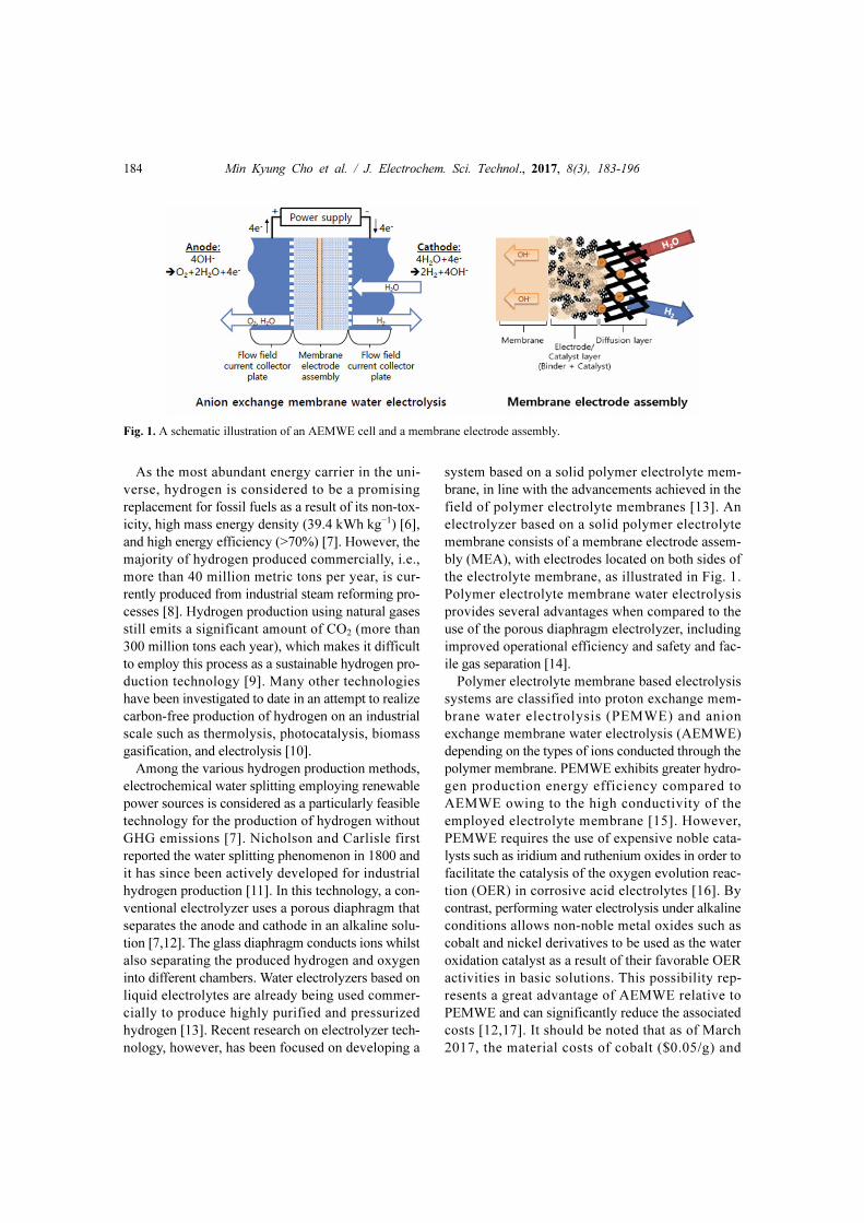
performance and durability. Fig. 2 shows the chemi-
cal structure of three different AEM backbones: PSF,
PPO, and PBI. In this section, we summarize the var-
ious AEMs that have been developed to date and
their properties and performances in AEMWE single
cells.
2.1 Polysulfone-based AEMs
PSF-based membranes possess several properties
that are advantages for AEMWE applications,
namely, they are chemically and mechanically stable
under highly basic conditions [97] and they are also
inexpensive and easy to synthesize. Xiao et al. con-
ducted an AEMWE cell test using a self-cross-link-
ing quaternary ammonia polysulfone (xQAPS) AEM
and non-noble metal based electrodes [89]. The Xiao
group developed the xQAPS based membrane in the
previous study and observed only 3% swelling at
90oC while maintaining an effective OH− mobility
(15 and 43 mS cm−2 at 20 and 90oC, respectively) in
liquid water after self-cross-linking [98]. MEAs for
the OER and HER were fabricated by pressing the
self-cross-linking xQAPS membrane between Ni/Fe-
coated Ni foam and Ni/Mo-coated stainless steel
fiber felt, respectively, at 80oC for 2 min at a pressure
of 2 MPa, and were subsequently tested in an
AEMWE cell configuration [89]. The cell exhibited a
water splitting current density of approximately
250 mA cm−2 at 1.8 V and 70oC. Moreover, the volt-
age was stable at approximately 1.8 V over 8 h of
constant current density operation at approximately
400 mA cm−2, with only a <3% increase in voltage
over this period. The authors expected that the MEA
performance could be further improved by reducing
the membrane/electrode contact resistance and by
using a better cathode catalyst [89].
Parrondo et al. studied the MEA performance of
PSF-based AEMs during AEMWE cell operation
and analyzed the mechanism of AEM degradation.
The AEMs were functionalized with different
groups: quaternary benzyl trimethylammonium
(PSF-TMA+OH−), quaternary benzyl quinuclidum
(PSF-ABCO+OH−), and quaternary benzyl 1-
methylimidazolium (PSF-1 M+OH−) [90]. The ionic
conductivities of PSF-TMA+OH−, PSF-ABCO+OH−,
and PSF-1M+OH− AEM at 50oC in liquid water were
estimated to be 17, 14, and 13 mS cm−1, respectively,
with all AEMs exhibiting the same theoretical IEC of
1.8 mmol g−1. The MEAs were fabricated with lead
Fig. 2. Chemical structures of example homogenous AEMs: (a) polysulfone (PSF), (b) poly(2,6-dimethyl-p-phylene) oxide
(PPO), and (c) polybenzimidazole (PBI).

Min Kyung Cho et al. / J. Electrochem. Sci. Technol., 2017, 8(3), 183-196 187
ruthenate pyrochlore and Pt black catalysts for the
OER and HER, respectively, and the water electroly-
sis was performed using ultra pure water at 50oC. The
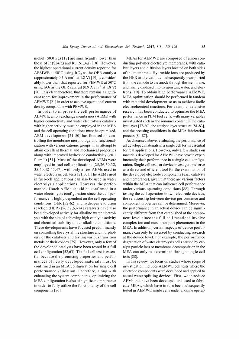
MEA utilizing the PSF-TMA+OH− membrane exhib-
ited the highest current density, which was estimated
to be about approximately 350 mA cm−2 at 1.8 V
from its polarization curve. By contrast, the MEAs
based on PSF-ABCO+OH− and PSF-1M+ OH− mem-
branes both exhibited a current density of approxi-
mately 200 mA cm−2 at 1.8 V, as shown in Fig. 3.
Three repeat polarization curve measurements
showed short-term performance degradation in the
PSF-TMA+OH−-membrane based MEA, with the
high-frequency resistance (HFR) gradually increas-
ing from 0.60 to 1.67 Ω cm2. The authors proved
experimentally that the short-term performance deg-
radation is caused mainly by the formation of carbon-
ate anions as a result of CO2 intrusion. They also
performed long-term operation tests using a constant
current density of 200 mA cm−2 at 50oC, and the
MEA based on the PSF-TMA+OH− membrane exhib-
ited the best performance. The cell voltage increased
from 1.6 to 2.4 V over 6 h of cell operation, which
was attributed to the degradation of the membrane
backbone using nuclear magnetic resonance (NMR)
spectroscopy. No functional group degradation was
observed in this system [90].
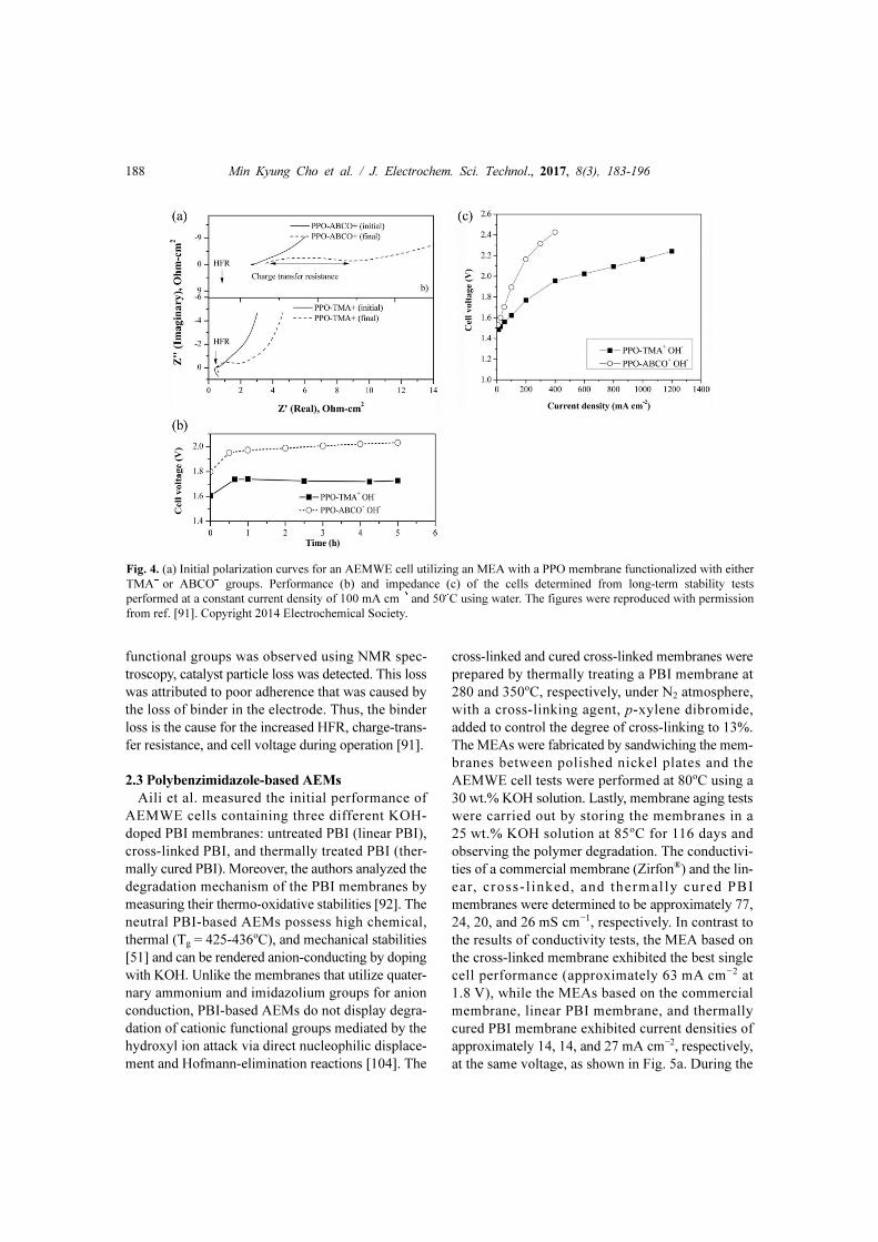
2.2 Polyphenylene Oxide-based AEMs
PPO displays a better stability in alkaline media
than PSF [99] and can be easily functionalized with
various cationic groups [100-102]. These properties
make it a good candidate for anion conducting poly-
mer electrolytes. In order to increase the ionic conduc-
tivity and stability of AEMs under high pH conditions,
Parrondo et al. developed PPO-based AEMs function-
alized with TMA+ or ABCO+ groups and compared
their initial performance and cell voltages during con-
stant current operation at 100 mA cm−2 [91]. The
authors also analyzed in detail the degradation mech-
anism of these AEMs during cell operation. The
TMA+- and ABCO+-functionalized PPO membranes
exhibited higher ionic conductivities than PSF [90] at
50oC in water, with values of approximately 44 (theo-
retical IEC of 2.1 mmol g−1) and 42 mS cm−1 (theo-
retical IEC of 1.9 mmol g−1), respectively [103]. For
the single cell study, the MEAs were prepared by
assembling a membrane with gas diffusion electrodes
coated with IrO2 and Pt black electrocatalysts for the
OER and HER, respectively. The AEMWE cell was
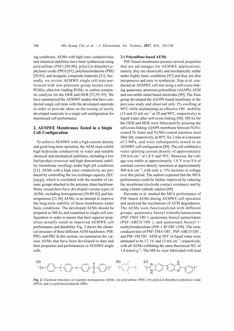
operated with ultrapure water at 50oC. The higher
ionic conductivity of the PPO-TMA+OH− membrane
resulted in a higher initial performance (approxi-
mately 230 mA cm−2 at 1.8 V) compared to PPO-
ABCO+OH− membrane (approximately 60 mA cm−2
at 1.8 V), as shown in Fig. 4a. The cell voltage
increased in comparison with the initial cell voltage
during the continued constant current operation, as
shown in Fig. 4b. Additionally, the HFR and charge-
transfer resistance of both cells were greater after cell
operation when compared to the initial values, as
shown in Fig. 4c. Although no degradation in AEM
Fig. 3. (a) Polarization curves for PSF membranes functionalized with various cationic groups. The current density was
increased from 10 to 700 mA cm−2. (b) Durability test for PSF-TMA+OH− MEA at a constant current density of 200 mA
cm−2 at 50oC using ultrapure water. The figures were reproduced with permission from ref. [90]. Copyright 2014 Royal
Society of Chemistry.
188 Min Kyung Cho et al. / J. Electrochem. Sci. Technol., 2017, 8(3), 183-196
functional groups was observed using NMR spec-
troscopy, catalyst particle loss was detected. This loss
was attributed to poor adherence that was caused by
the loss of binder in the electrode. Thus, the binder
loss is the cause for the increased HFR, charge-trans-
fer resistance, and cell voltage during operation [91].
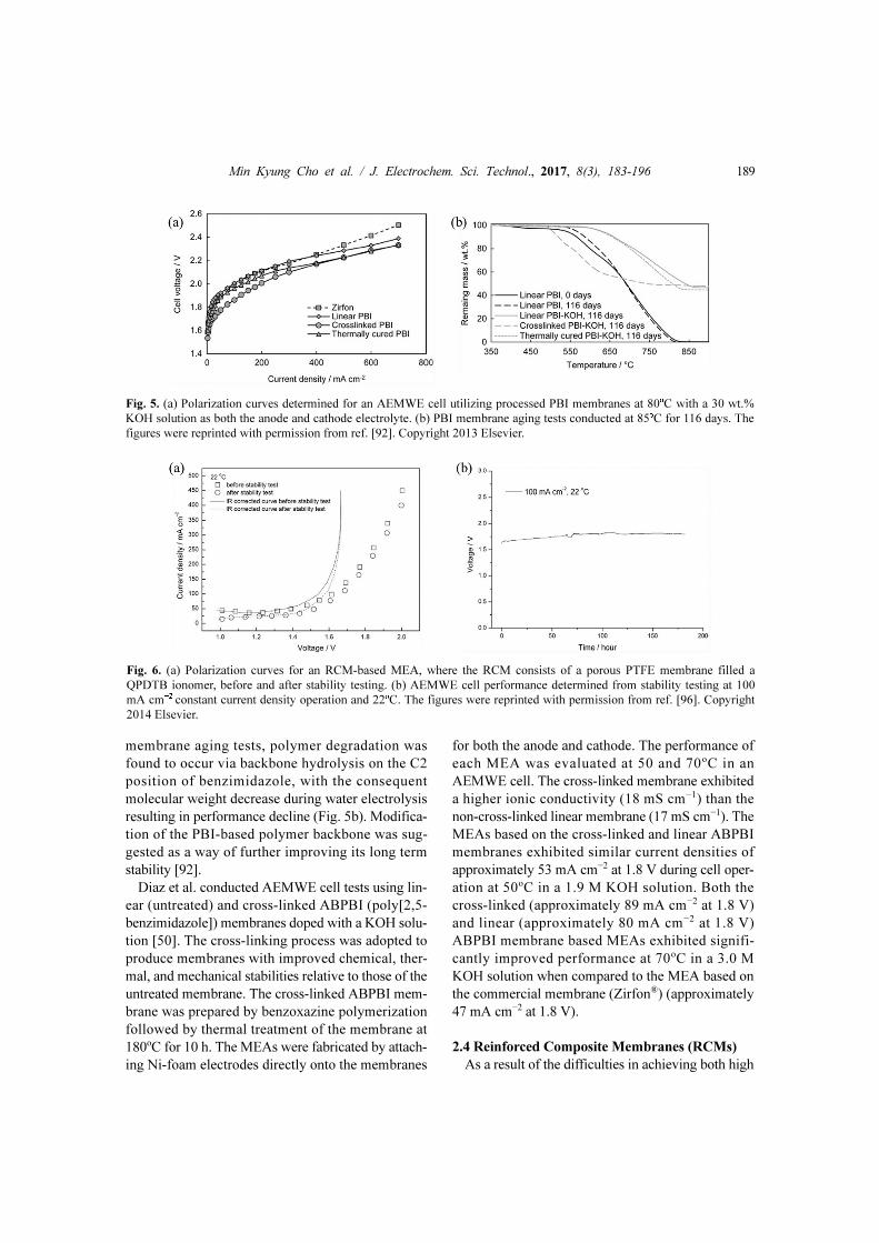
2.3 Polybenzimidazole-based AEMs
Aili et al. measured the initial performance of
AEMWE cells containing three different KOH-
doped PBI membranes: untreated PBI (linear PBI),
cross-linked PBI, and thermally treated PBI (ther-
mally cured PBI). Moreover, the authors analyzed the
degradation mechanism of the PBI membranes by
measuring their thermo-oxidative stabilities [92]. The
neutral PBI-based AEMs possess high chemical,
thermal (Tg = 425-436oC), and mechanical stabilities
[51] and can be rendered anion-conducting by doping
with KOH. Unlike the membranes that utilize quater-
nary ammonium and imidazolium groups for anion
conduction, PBI-based AEMs do not display degra-
dation of cationic functional groups mediated by the
hydroxyl ion attack via direct nucleophilic displace-
ment and Hofmann-elimination reactions [104]. The
cross-linked and cured cross-linked membranes were
prepared by thermally treating a PBI membrane at
280 and 350oC, respectively, under N2 atmosphere,
with a cross-linking agent, p-xylene dibromide,
added to control the degree of cross-linking to 13%.
The MEAs were fabricated by sandwiching the mem-
branes between polished nickel plates and the
AEMWE cell tests were performed at 80oC using a
30 wt.% KOH solution. Lastly, membrane aging tests
were carried out by storing the membranes in a
25 wt.% KOH solution at 85oC for 116 days and
observing the polymer degradation. The conductivi-
ties of a commercial membrane (Zirfon®) and the lin-
ear, cross- l inked, and thermal ly cured PBI
membranes were determined to be approximately 77,
24, 20, and 26 mS cm−1, respectively. In contrast to
the results of conductivity tests, the MEA based on
the cross-linked membrane exhibited the best single
cell performance (approximately 63 mA cm−2 at
1.8 V), while the MEAs based on the commercial
membrane, linear PBI membrane, and thermally
cured PBI membrane exhibited current densities of
approximately 14, 14, and 27 mA cm−2, respectively,
at the same voltage, as shown in Fig. 5a. During the
Fig. 4. (a) Initial polarization curves for an AEMWE cell utilizing an MEA with a PPO membrane functionalized with either
TMA+ or ABCO+ groups. Performance (b) and impedance (c) of the cells determined from long-term stability tests
performed at a constant current density of 100 mA cm−2 and 50oC using water. The figures were reproduced with permission
from ref. [91]. Copyright 2014 Electrochemical Society.
Min Kyung Cho et al. / J. Electrochem. Sci. Technol., 2017, 8(3), 183-196 189
membrane aging tests, polymer degradation was
found to occur via backbone hydrolysis on the C2
position of benzimidazole, with the consequent
molecular weight decrease during water electrolysis
resulting in performance decline (Fig. 5b). Modifica-
tion of the PBI-based polymer backbone was sug-
gested as a way of further improving its long term
stability [92].
Diaz et al. conducted AEMWE cell tests using lin-
ear (untreated) and cross-linked ABPBI (poly[2,5-
benzimidazole]) membranes doped with a KOH solu-
tion [50]. The cross-linking process was adopted to
produce membranes with improved chemical, ther-
mal, and mechanical stabilities relative to those of the
untreated membrane. The cross-linked ABPBI mem-
brane was prepared by benzoxazine polymerization
followed by thermal treatment of the membrane at
180oC for 10 h. The MEAs were fabricated by attach-
ing Ni-foam electrodes directly onto the membranes
for both the anode and cathode. The performance of
each MEA was evaluated at 50 and 70oC in an
AEMWE cell. The cross-linked membrane exhibited
a higher ionic conductivity (18 mS cm−1) than the
non-cross-linked linear membrane (17 mS cm−1). The
MEAs based on the cross-linked and linear ABPBI
membranes exhibited similar current densities of
approximately 53 mA cm−2 at 1.8 V during cell oper-
ation at 50oC in a 1.9 M KOH solution. Both the
cross-linked (approximately 89 mA cm−2 at 1.8 V)
and linear (approximately 80 mA cm−2 at 1.8 V)
ABPBI membrane based MEAs exhibited signifi-
cantly improved performance at 70oC in a 3.0 M
KOH solution when compared to the MEA based on
the commercial membrane (Zirfon®) (approximately
47 mA cm−2 at 1.8 V).
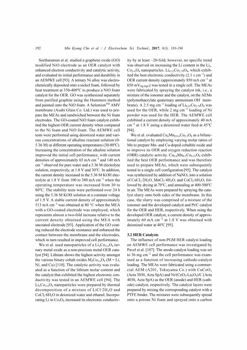
2.4 Reinforced Composite Membranes (RCMs)
As a result of the difficulties in achieving both high
Fig. 5. (a) Polarization curves determined for an AEMWE cell utilizing processed PBI membranes at 80oC with a 30 wt.%
KOH solution as both the anode and cathode electrolyte. (b) PBI membrane aging tests conducted at 85oC for 116 days. The
figures were reprinted with permission from ref. [92]. Copyright 2013 Elsevier.
Fig. 6. (a) Polarization curves for an RCM-based MEA, where the RCM consists of a porous PTFE membrane filled a
QPDTB ionomer, before and after stability testing. (b) AEMWE cell performance determined from stability testing at 100
mA cm−2 constant current density operation and 22oC. The figures were reprinted with permission from ref. [96]. Copyright
2014 Elsevier.

190 Min Kyung Cho et al. / J. Electrochem. Sci. Technol., 2017, 8(3), 183-196
ionic conductivity and chemical stability in AEMs
through the introduction of different functional
groups, reinforced composite membranes (RCMs)
[96] and inorganic membranes [21] have been devel-
oped as alternatives with the potential to attain both
ionic conductivity and stability, and subsequently
tested in AEMWE cells. Wu et al. evaluated the per-
formance of an RCM-based MEA in an AEMWE
single cell, where the RCM consisted of a porous
PTFE-supported composite membrane filled with a
polymethacrylate quaternary ammonium (QPDTB)
ionomer [96]. The RCM-based AEM was ultra-thin
(30 μm) and prepared by filling the PTFE membrane
pores with the QPDTB ionomer, which is an anion
conductor developed by Wu et al. in a previous study
[105]. The RCM exhibited an ionic conductivity of
34 mS cm−1 at 50oC. The MEA was fabricated by
spraying a catalyst slurry, consisting of the QPDTB
ionomer mixed with Cu0.6Mn0.3Co2.1O4 and Pt/C cat-
alyst for the OER and HER, respectively, onto the
RCM. The AEMWE cell stability was tested at 22oC
using pure water. The current density of the MEA
based on the RCM was approximately 200 mA cm−2
at 1.8 V, as shown in Fig. 6a. It is difficult to compare
the durability of this membrane with those of other
developed membranes as a result of the low operat-
ing temperature (22oC) employed in the stability test.
Nevertheless, the durability test revealed a perfor-
mance loss of 0.3% at 100 mA cm−2 over 120 h of
AEMWE cell operation, as shown in Fig. 6b [96].
2.5 Inorganic Membranes
Inorganic material based layered double hydrox-
ides (LDHs) have recently been developed for
AEMWE cells and have displayed excellent stabili-
ties and acceptable OH− ion conductivities during
single cell testing in alkaline media [106]. The use
LDHs can be advantageous not only because of their
good chemical stability, which is derived from the
absence of functional groups, but also because the
typical synthesis of LDH membranes does not
require the use of toxic or carcinogenic reagents
[21,106].
Zeng and Zhao monitored the long-term perfor-
mance of an AEMWE cell containing a low-cost
integrated inorganic MEA composed of an Mg-Al
LDH membrane. This membrane was designed to
overcome the challenges usually associated with
AEMs, i.e., low ionic conductivity, chemical instabil-
ity, and chemical toxicity of the corresponding syn-
thetic process [21]. The Mg-Al LDH membrane
exhibited superior stability in an alkaline environ-
ment and high OH− ion conductivity (7.7 mS cm−1)
under high relative humidity (98%) at 60oC. The
MEAs were prepared using the Mg-Al LDH mem-
brane and commercial OER (CuCoOx) and HER
(NiM/CeO2-La2O3/C) catalysts from Acta SpA.
Polarization curves for the AEMWE cells fabricated
with MEAs of varying thickness were measured at
50oC in 0.1 M NaOH solution, revealing current den-
sities of approximately 60, 38, and 26 mA cm−2 at
1.8 V for the 300-, 500- and 700-μm-thick MEAs,
respectively. The decrease in water splitting current
density with increasing membrane thickness was
caused by the increased ionic resistance, which was
determined to be 3.25, 5.11, and 7.39 Ω cm2 for the
300-, 500-, and 700-μm-thick MEAs, respectively, as
shown in Fig. 7 [21].
3. AEMWE Catalysts Tested in Single Cells
The cost of water electrolysis employing AEMWE
cells is lower when compared to the use of PEMWE
cells. This decrease in cost stems from the fact that
the alkaline electrolyzers employ inexpensive metals
or metal oxides as the HER and OER catalysts while
PEMWE requires costly PGM catalysts for the OER
in order to ensure sufficiently high reaction rates in
the acidic operating environment. The water splitting
OER kinetics are more facile in an alkaline environ-
Fig. 7. Polarization curves for integrated inorganic MEAs
containing Mg-Al LDH membranes of varying thickness.
The cell was operated at 60oC. The figure were reprinted
with permission from ref. [21]. Copyright 2015 Elsevier.

Min Kyung Cho et al. / J. Electrochem. Sci. Technol., 2017, 8(3), 183-196 191
ment than in an acidic environment. Thus, the OER
has been widely studied under alkaline conditions to
develop efficient non-PGM catalysts for cost effec-
tive water electrolysis. Many researchers developing
these catalysts perform half-cell tests to evaluate the
catalyst performance. However, although the half-
cell test can give promising results, single cell tests
are necessary in order to prove the utility of the cata-
lysts in the MEA catalyst layer [88]. In this section,
we review the research performed to date on the
AEMWE single cell performance of non-PGM cata-
lysts developed for the OER [52,93-95] and HER
[63,107].
3.1 OER Catalysts
The OER kinetics are more sluggish than the HER
kinetics and as a consequence, the performance of
water electrolysis depends strongly on the OER (a
four inner sphere electron transfer reaction). The
OER activities of electrocatalysts are generally
greater in higher pH solutions than in acidic or low
pH solutions. As a result, non-noble metal oxides can
be used as catalysts in AEMWE. Furthermore, water-
electrolysis systems operating under alkaline condi-
tions are more durable and stable than those operat-
ing under acidic conditions. For example, the OER
catalysts iridium oxide and ruthenium oxide exhibit
dissolution rates during potential scanning that are ca.
700 and 600 times lower, respectively, in a 0.05 M
NaOH electrolyte than in acidic media [108]. Metal
oxides are also often stable at high pH operating con-
ditions as a result of the formation of a surface pas-
sivation layer [109].
Parrondo et al. studied pyrochlore-structured metal
oxides, which are highly active and stable OER cata-
lysts. The authors performed AEMWE cell tests with
Pb2Ru2O6.5 and Bi2.4Ru1.6O7 pyrochlores, which
exhibit the highest OER mass and specific activities
of all pyrochlore electrocatalysts [52]. These
pyrochlore catalysts exhibited electronic conductivi-
ties of 120 ± 30 and 63 ± 5 S cm−1 for Pb2Ru2O6.5 and
Bi2.4Ru1.6O7, respectively, and their OER activities in
the AEMWE cell were comparable with that of IrO2
(also tested in this study) [52]. In a half-cell evalua-
tion, the OER mass activities of Pb2Ru2O6.5 and
Bi2.4Ru1.6O7 pyrochlores were determined to be 202
and 10 Ag−1, respectively, at 1.5 VRHE. The MEAs
were subsequently fabricated by spraying catalyst ink
(IrO2 or the pyrochlores and Pt black for the OER and
HER, respectively, mixed with an AEM binder) on a
commercial AEM membrane (A201, Tokuyama
Co.). The AEMWE cell was operated at 50oC and
exhibited a current density of approximately 250,
500, and 400 mA cm−2 at 1.8 Vcell when employing
IrO2, Pb2Ru2O6.5, and Bi2.4Ru1.6O7 as the OER cata-
lyst, respectively, as shown in Fig. 8a. The long-term
AEMWE cell performance was tested using Pb2-
Ru2O6.5, which showed the best initial performance.
The cell exhibited a constant voltage of 1.75 V over
200 h of constant current operation at 200 mA cm−2
[52]. The catalytic activity showed a strong relation-
ship with the strength of bonding between the B-site
cation of the pyrochlore and the reaction intermediate
species formed during the OER, as evidenced by the
reaction paths studied at the surfaces of the
pyrochlore.
Fig. 8. (a) Polarization curves reported for MEAs prepared with pyrochlore OER electrocatalysts measured at 50oC. (b)
AEMWE cell long-term performance during operation at 200 mA cm−2 and 35oC using a 1 wt.% KHCO3 solution. The
figures were reproduced with permission from ref. [52]. Copyright 2015 Royal Society of Chemistry.
192 Min Kyung Cho et al. / J. Electrochem. Sci. Technol., 2017, 8(3), 183-196
Seetharaman et al. studied a graphene oxide (GO)
modified NiO electrode as an OER catalyst with
enhanced electron conductivity and catalytic activity,
and evaluated its initial performance and durability in
an AEMWE cell [93]. A ternary Ni alloy was electro-
chemically deposited onto a nickel foam, followed by
heat treatment at 350-400oC to produce a NiO foam
catalyst for the OER. GO was synthesized separately
from purified graphite using the Hummers method
and painted onto the NiO foam. A SelemionTM AMV
membrane (Asahi Glass Co. Ltd.) was used to pre-
pare the MEAs and sandwiched between the Ni foam
electrodes. The GO-coated NiO foam catalyst exhib-
ited the highest OER current density when compared
to the Ni foam and NiO foam. The AEMWE cell
tests were performed using deionized water and vari-
ous concentrations of alkaline reactant solution (0-
5.36 M) at different operating temperatures (30-80oC).
Increasing the concentration of the alkaline solution
improved the initial cell performance, with current
densities of approximately 65 mA cm−2 and 140 mA
cm−2 observed for pure water and a 5.36 M electrolyte
solution, respectively, at 1.8 V and 30oC. In addition,
the current density increased in the 5.36 M KOH elec-
trolyte at 1.8 V from 100 to 380 mA cm−2 when the
operating temperature was increased from 30 to
80oC. The stability tests were performed over 24 h
using the 5.36 M KOH solution at a constant voltage
of 1.9 V. A stable current density of approximately
513 mA cm−2 was obtained at 80 °C when the MEA
with a GO-coated electrode was employed, which
represents almost a two-fold increase relative to the
current density obtained using the MEA with
uncoated electrode [93]. Application of the GO coat-
ing reduced the electrode resistance and enhanced the
contact between the membrane and the electrodes,
which in turn resulted in improved cell performance.
Wu et al. used nanoparticles of a LixCo3-xO4 ter-
nary metal oxide as a non-precious metal OER cata-
lyst [94]. Lithium shows the highest activity amongst
the various binary cobalt oxides MzCo3-xO4 (M = Li,
Ni, and Cu) [110]. The catalytic activity was evalu-
ated as a function of the lithium molar content and
the catalyst that exhibited the highest electronic con-
ductivity was tested in an AEMWE cell [94]. The
LixCo3-xO4 nanoparticles were prepared by thermal
decomposition of a mixture of LiCl·2H2O and
CoCl2·6H2O in deionized water and ethanol. Incorpo-
rating Li in Co3O4 increased its electronic conductiv-
ity by at least ~20-fold; however, no specific trend
was observed on increasing the Li content in the Lix-
Co3-xO4 nanoparticles. Li0.21Co2.79O4, which exhib-
ited the best electronic conductivity (2.1 s cm−1) and
OER current density (approximately 850 mA cm−1 at
650 mVHg/HgO) was tested in a single cell. The MEAs
were fabricated by spraying the catalyst ink, i.e., a
mixture of the ionomer and the catalyst, on the AEMs
(polymethacrylate quaternary ammonium OH− mem-
brane). A 2.5 mg cm−2 loading of Li0.21Co2.79O4 was
used for the OER, while 2 mg cm−2 loading of Ni
powder was used for the HER. The AEMWE cell
exhibited a current density of approximately 40 mA
cm−2 at 1.8 V using a deionized water feed at 45oC
[94].
Wu et al. evaluated CuxMn0.9-xCo2.1O4 as a bifunc-
tional catalyst by employing varying molar ratios of
Mn to prepare Mn- and Cu-doped cobaltite oxide and
to improve its OER and oxygen reduction reaction
(ORR) catalytic activity. Cu0.6Mn0.3Co0.21O4 exhib-
ited the best OER performance and was therefore
used to prepare MEAs, which were subsequently
tested in a single cell configuration [95]. The catalyst
was synthesized by addition of NaNO3 into a solution
of CuCl2·2H2O, MnCl2·4H2O, and CoCl2·6H2O, fol-
lowed by drying at 70oC, and annealing at 400-500oC
in air. The MEAs were prepared by spraying the cata-
lyst slurry onto both sides of the membrane. In this
case, the slurry was comprised of a mixture of the
ionomer and the developed catalyst and Pt/C catalyst
for the OER and HER, respectively. When using the
developed OER catalyst, a current density of approx-
imately 60 mA cm−2 at 1.8 V was obtained with
deionized water at 40oC [95].
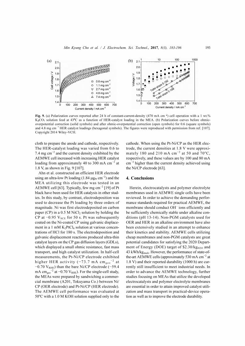
3.2 HER Catalysts
The influence of non-PGM HER catalyst loading
on AEMWE cell performance was investigated by
Pavel et al. [107]. The anode-catalyst loading was set
to 36 mg cm−2 and the cell performance was exam-
ined as a function of increasing cathode-catalyst
loading. The MEAs were fabricated using a commer-
cial AEM (A201, Tokuyama Co.) with CuCoOx
(Acta 3030, Acta SpA) and Ni/(CeO2-La2O3)/C (Acta
4030, Acta SpA) as the OER (anode) and HER (cath-
ode) catalyst, respectively. The catalyst layers were
prepared by mixing the corresponding catalyst with a
PTFE binder. The mixtures were subsequently spread
onto a porous Ni foam and sprayed onto a carbon
Min Kyung Cho et al. / J. Electrochem. Sci. Technol., 2017, 8(3), 183-196 193
cloth to prepare the anode and cathode, respectively.
The HER-catalyst loading was varied from 0.6 to
7.4 mg cm−2 and the current density exhibited by the
AEMWE cell increased with increasing HER catalyst
loading from approximately 40 to 300 mA cm−2 at
1.8 V, as shown in Fig. 9 [107].
Ahn et al. constructed an efficient HER electrode
using an ultra-low Pt loading (1.84 μgPt cm−2) and the
MEA utilizing this electrode was tested in an
AEMWE cell [63]. Typically, few mg cm−2 [19] of Pt
black have been used for HER catalysis in other stud-
ies. In this study, by contrast, electrodeposition was
used to decrease the Pt loading by three orders of
magnitude. Ni was first electrodeposited on carbon
paper (CP) in a 0.5 M NiCl2 solution by holding the
CP at −0.95 VSCE for 50 s. Pt was subsequently
coated on the Ni-coated CP using galvanic displace-
ment in a 1 mM K2PtCl6 solution at various concen-
trations of HCl for 180 s. The electrodeposition and
galvanic displacement reactions produced ultra-thin
catalyst layers on the CP gas diffusion layers (GDLs),
which displayed a small ohmic resistance, fast mass
transport, and high catalyst utilization. In half-cell
measurements, the Pt-Ni/CP electrode exhibited
higher HER act iv i ty (−73.7 mA cm g e o− 2 a t
−0.70 VRHE) than the bare Ni/CP electrode (−59.4
mA cmgeo−2 at −0.70 VRHE). For the single-cell study,
the MEAs were prepared by sandwiching a commer-
cial membrane (A201, Tokuyama Co.) between Ni/
CP (OER electrode) and Pt-Ni/CP (HER electrode).
The AEMWE cell performance was evaluated at
50oC with a 1.0 M KOH solution supplied only to the
cathode. When using the Pt-Ni/CP as the HER elec-
trode, the current densities at 1.8 V were approxi-
mately 180 and 210 mA cm−2 at 50 and 70oC,
respectively, and these values are by 100 and 80 mA
cm−2 higher than the current density achieved using
the Ni/CP electrode [63].
4. Conclusions
Herein, electrocatalysts and polymer electrolyte
membranes used in AEMWE single cells have been
reviewed. In order to achieve the demanding perfor-
mance standards required for practical AEMWE, the
membrane should conduct OH− ions efficiently and
be sufficiently chemically stable under alkaline con-
ditions (pH 13-14). Non-PGM catalysts used for
OER and HER in an alkaline environment have also
been extensively studied in an attempt to enhance
their kinetics and stability. AEMWE cells utilizing
cheap membranes and non-PGM catalysts are great
potential candidates for satisfying the 2020 Depart-
ment of Energy (DOE) target of $2.30/kgH2O and
43 kWh/kgstack. However, the performance of state-of-
the-art AEMWE cells (approximately 530 mA cm−2 at
1.8 V) and their reported durability (1000 h) are cur-
rently still insufficient to meet industrial needs. In
order to advance the AEMWE technology, further
studies focusing on MEAs that utilize the developed
electrocatalysts and polymer electrolyte membranes
are essential in order to attain improved catalyst utili-
zation and mass transport in practical-device opera-
tion as well as to improve the electrode durability.
Fig. 9. (a) Polarization curves reported after 24 h of constant-current-density (470 mA cm−2) cell operation with a 1 wt.%
K2CO3 solution feed at 43oC as a function of HER-catalyst loading in the MEA. (b) Polarization curves before ohmic-
overpotential correction (solid symbols) and after ohmic-overpotential correction (open symbols) for 0.6 (square symbols)
and 4.8 mg cm−2 HER catalyst loadings (hexagonal symbols). The figures were reproduced with permission from ref. [107].
Copyright 2014 Wiley-VCH.

194 Min Kyung Cho et al. / J. Electrochem. Sci. Technol., 2017, 8(3), 183-196
Acknowledgement
This work was supported by the New and Renew-
able Energy Core Technology Program of the Korea
Institute of Energy Technology Evaluation and Plan-
ning (KETEP) funded by the Ministry of Trade,
Industry and Energy, Republic of Korea (MOTIE,
Grant No. 20143010031770). This study was also
financially supported by the KIST through the Insti-
tutional Project.
References
[1] A.B. Rao, E.S. Rubin, Environ. Sci. Technol., 2002,36(20), 4467-4475.
[2] Hoffert, Martin I., et al., Science, 2002, 298(5595), 981-987.
[3] J.M. Reilly, The Bridge, 2015, 45(2), 6-15.[4] R. Jackson, P. Friedlingstein, J. Canadell, R. Andrew,
The Bridge, 2015, 45(2), 16-21.[5] S. Kerdsuwan, K. Laohalidanond, Energy Procedia,
2015, 79, 125-130.[6] A. Züttel, Mitigation and Adaptation Strategies for
Global Change, 2007, 12(3), 343-365.[7] K. Christopher, R. Dimitrios, Energy Environ.Sci., 2012,
5(5, 6640-6651.[8] M. Melaina, M. Penev, D. Heimiller, NREL technical
report, 2013, NREL/TP-5400-55626.[9] G. Collodi, F. Wheeler, Chem.Eng.Trans., 2010, 19, 37-
42.[10] G. Simbolotti, IEA Energy Technology Essentials, IEA,
2007. [11] W. Kreuter, H. Hofmann, Int. J.Hydrogen Energy, 1998,
23(8), 661-666.[12] K. Zeng, D. Zhang, Prog. Energy Combust. Sci., 2010,
36(3), 307-326.[13] J.D. Holladay, J. Hu, D.L. King, Y. Wang, Catal.Today,
2009, 139(4), 244-260.[14] P. Millet, F. Andolfatto, R. Durand, Int. J. Hydrogen
Energy, 1996, 21, 87-93.[15] A. Goñi-Urtiaga, D. Presvytes, K. Scott, Int. J.
Hydrogen Energy, 2012, 37(4), 3358-3372.[16] K. Ito, T. Sakaguchi, Y. Tsuchiya, Polymer Electrolyte
Membrane Water Electrolysis, in: Hydrogen Energy
Engineering, Springer, (2016) 143-149.[17] J.R. McKone, N.S. Lewis, H.B. Gray, Chem.Mater.,
2013, 26(1), 407-414.[18] InfoMine Inc. (2017) Retrieved March, 2017, from http:/
/www.infomine.com/ investment/metal-prices.[19] Y. Leng, G. Chen, A.J. Mendoza, T.B. Tighe, M.A.
Hickner, C.-Y. Wang, J. Am. Chem. Soc., 2012, 134(22),
9054-9057.[20] V.K. Puthiyapura, S. Pasupathi, H. Su, X. Liu, B. Pollet, K.
Scott, Int. J. Hydrogen Energy, 2014, 39(5), 1905-1913.[21] L. Zeng, T.S. Zhao, Nano Energy, 2015, 11, 110-118.
[22] D. Lu, D. Li, L. Wen, L. Xue, J. Membr.Sci., 2017, 533,
210-219.[23] H. Wu, W. Jia, Y. Liu, J. Mater. Sci., 2017, 52(3), 1704-
1716.[24] X. Gong, X. Yan, T. Li, X. Wu, W. Chen, S. Huang, Y.
Wu, D. Zhen, G. He, J. Membr. Sci., 2017, 523, 216-224.[25] X. He, X. Jiang, Z. Wang, Y. Deng, Z. Han, Y. Yang, D.
Chen, Polym. Eng. Sci., 2017 (Browse Early ViewArticle, DOI: 10. 1002/pen.24524).
[26] WANG, Lianqin, et al., Green Chemistry, 2017, 19(3),
831-843.[27] J. Li, X. Yan, X. Ruan, W. Zheng, G. He, J. Dai, R.
Deng, Polym. Mater. Sci. Eng., 2016, 32, 38-42.[28] Z. Hu, W. Tang, D. Ning, X. Zhang, H. Bi, S. Chen,
Fuel Cells, 2016, 16(5), 557-567.[29] C. Wang, B. Lin, G. Qiao, L. Wang, L. Zhu, F. Chu, T.
Feng, N. Yuan, J. Ding, Mater. Lett., 2016, 173, 219-222.
[30] T. Bayer, B.V. Cunning, R. Selyanchyn, T. Daio, M.Nishihara, S. Fujikawa, K. Sasaki, S.M. Lyth, J.
Membr.Sci., 2016, 508, 51-61.[31] T. Feng, B. Lin, S. Zhang, N. Yuan, F. Chu, M.A.
Hickner, C. Wang, L. Zhu, J. Ding, J. Membr.Sci., 2016,508, 7-14.
[32] A.G. Wright, J. Fan, B. Britton, T. Weissbach, H.F. Lee,E.A. Kitching, T.J. Peckham, S. Holdcroft, Energy
Environ. Sci., 2016, 9(6), 2130-2142.[33] B. Shi, Y. Li, H. Zhang, W. Wu, R. Ding, J. Dang, J.
Wang, J. Membr.Sci., 2016, 498, 242-253.[34] Z. Li, W. Wang, Y. Chen, C. Xiong, G. He, Y. Cao, H.
Wu, M.D. Guiver, Z. Jiang, J. Mater. Chem. A, 2016,4(6), 2340-2348.
[35] C. Yang, S. Wang, W. Ma, S. Zhao, Z. Xu, G. Sun, J.
Mater. Chem. A, 2016, 4(10), 3886-3892.[36] D. Lu, L. Wen, L. Xue, RSC Adv., 2016, 6(75), 71431-
71440.[37] J. Li, X. Yan, Y. Zhang, B. Zhao, G. He, RSC Adv.,
2016, 6(63), 58380-58386.[38] P. Papakonstantinou, V. Deimede, RSC Adv., 2016,
6(115), 114329-114343.[39] Y. Yang, N. Sun, P. Sun, L. Zheng, RSC Adv., 2016,
6(30), 25311-25318.[40] F. Song, Y. Fu, Y. Gao, J. Li, J. Qiao, X.D. Zhou, Y. Liu,
Electrochim. Acta, 2015, 177, 137-144.[41] Y. Gao, F. Song, J. Qiao, S. Chen, X. Zhao, J. Zhang,
Electrochim. Acta, 2015, 177, 201-208.[42] L. Wu, Q. Pan, J.R. Varcoe, D. Zhou, J. Ran, Z. Yang,
T. Xu, J. Membr. Sci., 2015, 490, 1-8.[43] C. Yang, S. Wang, W. Ma, L. Jiang, G. Sun, J. Membr.
Sci., 2015, 487, 12-18.[44] C. Yang, S. Wang, W. Ma, L. Jiang, G. Sun, J. Mater.
Chem. A, 2015, 3(16), 8559-8565.[45] S.D. Poynton, J.R. Varcoe, Solid State Ionics, 2015, 277,
38-43.[46] W.-H. Lee, A.D. Mohanty, C. Bae, ACS Macro Lett.,
2015, 4(4), 453-457.

Min Kyung Cho et al. / J. Electrochem. Sci. Technol., 2017, 8(3), 183-196 195
[47] J. Fang, Y. Wu, Y. Zhang, M. Lyu, J. Zhao, Int. J.
Hydrogen Energy, 2015, 40(36), 12392-12399.[48] S. Chen, Y. Song, F. Song, X. Zhao, J. Qiao, X.-D.
Zhou, ECS Trans., 2015, 66(3), 111-116.[49] Z. Li, Z. Jiang, H. Tian, S. Wang, B. Zhang, Y. Cao, G.
He, Z. Li, H. Wu, J. Power Sources, 2015, 288, 384-392.
[50] L.A. Diaz, J. Hnát, N. Heredia, M.M. Bruno, F.A. Viva,M. Paidar, H.R. Corti, K. Bouzek, G.C. Abuin, J. Power
Sources, 2016, 312, 128-136.[51] G. Merle, M. Wessling, K. Nijmeijer, J. Membr. Sci.,
2011, 377(1), 1-35.[52] J. Parrondo, M. George, C. Capuano, K.E. Ayers, V.
Ramani, J. Mater. Chem. A, 2015, 3(20), 10819-10828.[53] T. Zhan, X. Liu, S. Lu, W. Hou, Appl. Catal., B, 2017,
205, 551-558.[54] J. Yang, T. Fujigaya, N. Nakashima, Sci. Rep., 2017, 7,
45384-45392.[55] S. Dutta, C. Ray, Y. Negishi, T. Pal, ACS Appl. Mater.
Interfaces, 2017, 9, 8134-8141.[56] Z.-Y. Yu, Y. Duan, M.-R. Gao, C.-C. Lang, Y.-R. Zheng,
S.-H. Yu, Chemical Science, 2017, 8(2), 968-973.[57] Y. Jin, X. Yue, C. Shu, S. Huang, P.K. Shen, J. Mater.
Chem. A, 2017, 5(6), 2508-2513.[58] X. Chen, G. Zeng, T. Gao, Z. Jin, Y. Zhang, H. Yuan, D.
Xiao, Electrochem. Commun., 2017, 74, 42-47.[59] Y. Fang, X. Li, S. Zhao, J. Wu, F. Li, M. Tian, X. Long,
J. Jin, J. Ma, RSC Adv., 2016, 6(84), 80613-80620.[60] J. Wang, K. Li, H.x. Zhong, D. Xu, Z.l. Wang, Z. Jiang,
Z.j. Wu, X.b. Zhang, Angew. Chem. Int. Ed., 2015,54(36), 10530-10534.
[61] B. Jović, U. Lačnjevac, V. Jović, N. Krstajić, J.
Electroanal. Chem., 2015, 754, 100-108.[62] P. Hosseini-Benhangi, M.A. Garcia-Contreras, A.
Alfantazi, E.L. Gyenge, J. Electrochem. Soc., 2015,162(12), F1356-F1366.
[63] S.H. Ahn, S.J. Yoo, H.-J. Kim, D. Henkensmeier, S.W.Nam, S.-K. Kim, J.H. Jang, Appl. Catal., B, 2016, 180,
674-679.[64] W. Badawy, H. Nady, G.A. El-Hafez, J. Alloys Compd.,
2017, 699, 1146-1156.[65] R. Solmaz, A. Salcı, H. Yüksel, M. Doğrubaş, G. Kardaş,
Int. J. Hydrogen Energy, 2017, 42(4), 2464-2475.[66] P. Jiang, Y. Yang, R. Shi, G. Xia, J. Chen, J. Su, Q.
Chen, J. Mater. Chem. A, 2017, 5(11), 5475-5485.[67] M. Gao, C. Yang, Q. Zhang, Y. Yu, Y. Hua, Y. Li, P.
Dong, Electrochim. Acta, 2016, 215, 609-616.[68] B. Zhang, H.-H. Wang, H. Su, L.-B. Lv, T.-J. Zhao, J.-
M. Ge, X. Wei, K.-X. Wang, X.-H. Li, J.-S. Chen, Nano
Res., 2016, 9(9), 2606-2615.[69] C. González-Buch, I. Herraiz-Cardona, E.M. Ortega, S.
Mestre, V. Pérez-Herranz, Int. J. Hydrogen Energy,2016, 41(2), 764-772.
[70] R. Kavian, S.-I. Choi, J. Park, T. Liu, H.-C. Peng, N. Lu,J. Wang, M.J. Kim, Y. Xia, S.W. Lee, J. Mater. Chem. A,2016, 4(32), 12392-12397.
[71] B. Pierozynski, T. Mikolajczyk, Electrocatalysis, 2016,7(2), 121-126.
[72] Y. Liu, G.-D. Li, L. Yuan, L. Ge, H. Ding, D. Wang, X.Zou, Nanoscale, 2015, 7(7), 3130-3136.
[73] B. Jović, V. Jović, U. Lačnjevac, L. Gajić-Krstajić, N.Krstajić, Int. J. Hydrogen Energy, 2015, 40(33), 10480-10490.
[74] M. Wang, Z. Wang, X. Yu, Z. Guo, Int. J. Hydrogen
Energy, 2015, 40(5), 2173-2181.[75] L. Han, S. Dong, E. Wang, Adv. Mater., 2016, 28, 9266-
9291.[76] B. Bladergroen, H. Su, S. Pasupathi, V. Linkov,
Overview of Membrane Electrode Assembly Preparation
Methods for Solid Polymer electrolyte Electrolyzer, in:D.J. Kleperis (Ed.) Electrolysis, InTech, 2012.
[77] T. Suzuki, S. Tsushima, S. Hirai, Int. J. Hydrogen
Energy, 2011, 36(19), 12361-12369.[78] K.-H. Kim, K.-Y. Lee, H.-J. Kim, E. Cho, S.-Y. Lee, T.-
H. Lim, S.P. Yoon, I.C. Hwang, J.H. Jang, Int. J.
Hydrogen Energy, 2010, 35(5), 2119-2126.[79] S. Jeon, J. Lee, G.M. Rios, H.-J. Kim, S.-Y. Lee, E. Cho,
T.-H. Lim, J. Hyun Jang, Int. J. Hydrogen Energy, 2010,35(18), 9678-9686.
[80] M.K. Cho, H.-Y. Park, S.Y. Lee, B.-S. Lee, H.-J. Kim,D. Henkensmeier, S.J. Yoo, J.Y. Kim, J. Han, H.S. Park,Y.-E. Sung, J.H. Jang, Electrochim. Acta, 2017, 224,
228-234.[81] D.S. Hwang, C.H. Park, S.C. Yi, Y.M. Lee, Int. J.
Hydrogen Energy, 2011, 36(16), 9876-9885.[82] S. Kamarajugadda, S. Mazumder, J. Power Sources,
2008, 183(2), 629-642.[83] Y. Qiu, H. Zhang, H. Zhong, F. Zhang, Int. J. Hydrogen
Energy, 2013, 38(14), 5836-5844.[84] M. Yazdanpour, A. Esmaeilifar, S. Rowshanzamir, Int. J.
Hydrogen Energy, 2012, 37(15), 11290-11298.[85] A. Therdthianwong, P. Manomayidthikarn, S.
Therdthianwong, Energy, 2007, 32(12), 2401-2411.[86] O. Okur, Ç. İyigün Karadağ, F.G. Boyacı San, E.
Okumuş, G. Behmenyar, Energy, 2013, 57, 574-580.[87] Z.X. Liang, T.S. Zhao, C. Xu, J.B. Xu, Electrochim.
Acta, 2007, 53(2), 894-902.[88] J. Zhang, H. Zhang, J. Wu, J. Zhang, Chapter 3 -
Techniques for PEM Fuel Cell Testing and Diagnosis,
in: Pem Fuel Cell Testing and Diagnosis, Elsevier,Amsterdam, 2013.
[89] L. Xiao, S. Zhang, J. Pan, C. Yang, M. He, L. Zhuang,J. Lu, Energy Environ. Sci., 2012, 5(7), 7869-7871.
[90] J. Parrondo, C.G. Arges, M. Niedzwiecki, E.B.Anderson, K.E. Ayers, V. Ramani, RSC Adv., 2014,4(19), 9875-9879.
[91] J. Parrondo, V. Ramani, J. Electrochem. Soc., 2014,161(10), F1015-F1020.
[92] D. Aili, M.K. Hansen, R.F. Renzaho, Q. Li, E.Christensen, J.O. Jensen, N.J. Bjerrum, J. Membr. Sci.,2013, 447, 424-432.
[93] S. Seetharaman, R. Balaji, K. Ramya, K.S.

196 Min Kyung Cho et al. / J. Electrochem. Sci. Technol., 2017, 8(3), 183-196
Dhathathreyan, M. Velan, Int. J. Hydrogen Energy,2013, 38(35), 14934-14942.
[94] X. Wu, K. Scott, Int. J. Hydrogen Energy, 2013, 38(8),
3123-3129.[95] X. Wu, K. Scott, J. Power Sources, 2012, 206, 14-19.[96] X. Wu, K. Scott, F. Xie, N. Alford, J. Power Sources,
2014, 246, 225-231.[97] A. Abdelrasoul, H. Doan, A. Lohi, C.-H. Cheng,
ChemBioEng Reviews, 2015, 2(1), 22-43.[98] J. Pan, Y. Li, L. Zhuang, J. Lu, Chemical
Communications, 2010, 46(45), 8597-8599.[99] Varcoe, John R., et al., Energy Environ. Sci., 2014,
7(10), 3135-3191.[100] N.T. Rebeck, Y. Li, D.M. Knauss, Journal of Polymer
Science Part B: Polymer Physics, 2013, 51(24), 1770-1778.
[101] Z. Wang, J. Parrondo, V. Ramani, J. Electrochem. Soc.,2016, 163(8), F824-F831.
[102] K.H. Gopi, S.G. Peera, S.D. Bhat, P. Sridhar, S.Pitchumani, Int. J. Hydrogen Energy, 2014, 39(6),
2659-2668.
[103] C.G. Arges, L. Wang, J. Parrondo, V. Ramani, J.
Electrochem. Soc., 2013, 160(11), F1258-F1274.[104] Y.S. Li, T.S. Zhao, Int. J. Hydrogen Energy, 2012,
37(5), 4413-4421.[105] X. Wu, K. Scott, J. Power Sources, 2012, 214, 124-
129.[106] Y. Furukawa, K. Tadanaga, A. Hayashi, M.
Tatsumisago, Solid State Ionics, 2011, 192(1), 185-187.[107] C.C. Pavel, F. Cecconi, C. Emiliani, S. Santiccioli, A.
Scaffidi, S. Catanorchi, M. Comotti, Angew. Chem. Int.
Ed., 2014, 53(5), 1378-1381.[108] S. Cherevko, S. Geiger, O. Kasian, N. Kulyk, J.-P.
Grote, A. Savan, B.R. Shrestha, S. Merzlikin, B.Breitbach, A. Ludwig, K.J.J. Mayrhofer, Catal. Today,2016, 262, 170-180.
[109] Z. Feng, W.T. Hong, D.D. Fong, Y.-L. Lee, Y. Yacoby,D. Morgan, Y. Shao-Horn, Acc. Chem. Res., 2016,49(5), 966-973.
[110] I. Nikolov, R. Darkaoui, E. Zhecheva, R. Stoyanova, N.Dimitrov, T. Vitanov, J. Electroanal. Chem., 1997,429(1-2), 157-168.