a prioritized multi-channel multi-time slot mac protocol ... · a prioritized multi-channel...
TRANSCRIPT

HAL Id: inria-00435517https://hal.inria.fr/inria-00435517
Submitted on 24 Nov 2009
HAL is a multi-disciplinary open accessarchive for the deposit and dissemination of sci-entific research documents, whether they are pub-lished or not. The documents may come fromteaching and research institutions in France orabroad, or from public or private research centers.
L’archive ouverte pluridisciplinaire HAL, estdestinée au dépôt et à la diffusion de documentsscientifiques de niveau recherche, publiés ou non,émanant des établissements d’enseignement et derecherche français ou étrangers, des laboratoirespublics ou privés.
A Prioritized Multi-Channel Multi-Time slot MACProtocol For Large-Scale Wireless Sensor Networks
Jamila Ben Sliman, Ye-Qiong Song, Anis Koubâa
To cite this version:Jamila Ben Sliman, Ye-Qiong Song, Anis Koubâa. A Prioritized Multi-Channel Multi-Time slot MACProtocol For Large-Scale Wireless Sensor Networks. ComNet’09: The First International Conferenceon Communications, and Networking, Nov 2009, Hammamet, Tunisia. pp.8, 2009. <inria-00435517>

A Prioritized Multi-Channel Multi-Time slot MACProtocol For Large-Scale Wireless Sensor Networks
Jamila Ben Slimane∗‡, Ye-Qiong Song‡ and Anis Koubaa§¶∗Sup’Com-MEDIATRON, City of Communication Technologies, 2083 Ariana, Tunisia‡LORIA and INPL, Campus Scientifique, BP 239 54506 Vandoeuvre-les-Nancy, France
§IPP-HURRAY! Research Group, Polytechnic Institute of Porto,Rua Antnio Bernardino de Almeida, 431, 4200-072 Porto, Portugal
¶Al-Imam Muhammad ibn Saud University, Computer Science Dept., 11681 Riyadh, Saudi ArabiaEmail: [email protected], [email protected], [email protected]
Abstract—This paper addresses a new prioritized multi-channel multi-time slot MAC protocol (PMCMTP) for large-scaleWSNs especially for Ultra-Wide Band (UWB) based networks.To reduce the complexity of resource sharing, the global networkis composed of a set of Personal Area Networks (PANs) orcells. According to available resource and PANs duty cycle,PMCMTP can dynamically assign several data channels per PANand efficiently allocate time slots to each PAN’s members. Thissignificantly decreases delay and increases throughput. Throughsome simulations, we evaluate the performance of the proposedprotocol. The results show that PMCMTP ensures an efficientand fair channels allocation between cells permitting, on the onehand, an enhancement of quality-of-service inside each PAN and,on the other hand, a maximization of channel utility.
I. INTRODUCTION
Wireless sensor networks may consist of a collection ofspatially distributed autonomous sensor nodes characterizedby limited memory, processing capability and battery powersupply. Such networks represent an emerging technologywith wide range of potential applications such as medicalsystems, environment monitoring, military applications, etc.An important fact that can not be neglected in WSNs isthe need of quality-of-service (QoS) support. According tonovel application requirements, QoS constraints become moreand more critical in terms of end-to-end delay and datathroughput. Also, due to energetic constraints at node level,energy saving remains the most challenging issue. Both IEEE802.15.4 and its recent amendment IEEE 802.15.4a standardsallow dynamic channel allocation and use of multiple channelsavailable at their physical layers but its MAC protocols aredesigned only for single channel. Also, sensor’s transceiverssuch as CC2420 used by current WSN hardware (MICAZ,TelosB, and CMU FireFly), provide multiple channels andas shown in [1] and [2] channel switch latency of CC2420transceiver is short (just about 200µs). However, in the generalcase of dense Mesh WSNs, the exploitation of the multi-channel access is complex. This explains the imperative needto propose an adequate network architecture that can simplifyand reduce the complexity of the resource sharing task in suchnetworks and to design a scalable and optimal multi-frequencyMAC protocols. Multi-channel Media Access Control (MAC)protocols should allow parallel transmissions with efficient
use of available resource (channels and time slots), withoutinterference, data communication conflict and control packetoverhead. Most currently deployed sensor networks use thesame channel to communicate information towards nodes.This is a source of great inefficiency as it poorly utilizesthe available wireless spectrum. This paper takes advantageof radio communication capabilities of IEEE 802.15.4a IR-UWB compliant devices that benefit from UWB technologyadvantages as specified in the IEEE 802.15.4a standard andthat can communicate on multiple frequencies as specified inthe IEEE 802.15.4 standard.The main problem addressed is designing an efficient pri-oritized multi-channel and multi-time slot allocation MACprotocol for dense and large-scale WSNs based principally onthe IEEE 802.15.4a IR-UWB physical layer. Our paper makesthe following main contributions:- First, focusing on UWB technology, it provides the firstspectrum management scheme exclusively for full mesh Large-scale WSNs.- Second, it proposes PMCMTP, a Prioritized Multi-ChannelMulti-Time slot media access control Protocol for dense andlarge-scale WSNs to ensure an efficient resource allocation, interms of channel frequencies and time slots inside each PAN,obeying to QoS constraints (i.e priority of resource requests).PMCMTP takes into account: the spatial channel reuse, theduty cycle’s information of PANs and the support of datastream prioritization.- Finally, using simulations, we perform an evaluation ofour protocol, demonstrating that it comes to reach our goalsin terms of spectrum efficiency and network performanceenhancement.
A. Related Works
Designing a good MAC protocol represents one of the mostchallenging tasks that enable the successful operation of thenetwork and the improvement of its performance. The majorityof WSNs use a single channel for control and data traffic whatleads to a complex problem of resource sharing especially indense and large scale networks. Although multi-channel accessprotocols for WSNs are not new issues and have been a topicof research in such networks, proposed protocols are really
very few. The principle of frequency allocation is firstly usedin cellular networks like Global System for Mobile commu-nications (GSM) [3]. In GSM networks, channel allocationis a function of network sizing (taking into account trafficdistribution and subscriber model) and cellular planning, sothe minimum distance of frequency reuse D =
√3K × R
where R represents the cell’s radius and K represents thecluster’s scale. However in WSNs, frequency reuse is a func-tion of sensor’s coverage, duty cycle of network’s membersand network’s topology. In the literature, a number of multi-channel MAC protocols have been proposed for WSNs [4]–[8].The first multi-channel protocol, called Multi-frequency Mediaaccess control for wireless Sensor Networks (MMSN) [4],represents four frequency assignment schemes for WSN: ex-clusive frequency assignment, even selection, eavesdroppingand implicit-consensus. The first scheme is used when thenumber of available frequencies is at least as large as thetwo-hop node number, it allocates channels in such a waythat nodes within two hops are assigned different frequencies.Due to several broadcasts, the communication overhead in thisscheme is relatively high. The second scheme ensures smalleroverhead but it requires more physical frequencies that is,it assumes that frequency resource are abundant. Given thatthe two other schemes do not guarantee the assignment ofdifferent frequencies to two-hop neighbors, potential conflictscan not be avoided. Moreover, we note that MMSN’s schemesallocate channels in static way which limits channel utilities asa node does not permanently use its assigned channel. In [5]and [6], the authors proposed a dynamic channel allocationbased on agreement established between each sender andreceiver nodes. Such approach may be suitable in light networkbut in dense network frequency negotiation messages caninvolve a considerable unnecessary overhead (e.g negotiationmessage retransmissions following their reception failure). Theadvantage of those protocols is the use of several channelsfor control traffic which can avoid control channel congestionproblem. All previous multi-channel allocation schemes areproposed for classical WSNs operating on 2.4 Ghz bandwithout any support of quality-of-service (QoS) mechanisms,however the authors in [7] proposed the first Multi-ChannelMAC protocol (MCMAC) taking into account the notion ofpriority during channel allocation process inside a cluster.In [8], the authors proposed the first multi-channel schemedesigned for UWB based IEEE 802.15.3 networks. Based ondynamic traffic demand, the proposed mechanism employs adistributed dynamic channel allocation algorithm (DCA) [9]to distribute the channels among neighboring piconets. Dueto several broadcasts (between PNCs (piconet controllers)),the communication overhead in this mechanism is relativelyhigh. To support the channel allocation scheme, PNCs mustbe always active which represents an unacceptable conditionon WSNs given the energetic constraints at WSN’s nodeslevel. Then, inside each piconet, time slots are allocated basedon MULTI-FIT [8] and Interval Based Scheduling (IBS) [8]algorithms to convert, in first step, the demand matrix into aspecific form and to allocate time slots per available channels,
in second step. Given that IBS algorithm is proposed to ensuretime slot allocation for networks based on a star topology,resource allocation (Time slots per available channels) forMulti-Hop Wireless Mesh Networks can not be supported bythis mechanism. Moreover, IBS does not provide any prioritypolicy ensuring quality-of-service support. Similar to [8], wepropose to organize the global network on set of PANs, toreduce the complexity of resource sharing. But, for channeland time slot allocation in UWB based WSNs, we propose amechanism that obeys, on the one hand, to WSNs constraintsand ensures, on the other hand, QoS support in such networks.The rest of the paper is organized as follows: In section 2,we present the system model. Section 3 details the proposedprioritized multi-channel and multi-time slot MAC protocol(PMCMTP). In section 4, we evaluate PMCMTP performanceby analyzing and commenting some results.
II. SYSTEM MODEL
A. IEEE 802.15.4a IR-UWB Spectrum Resource
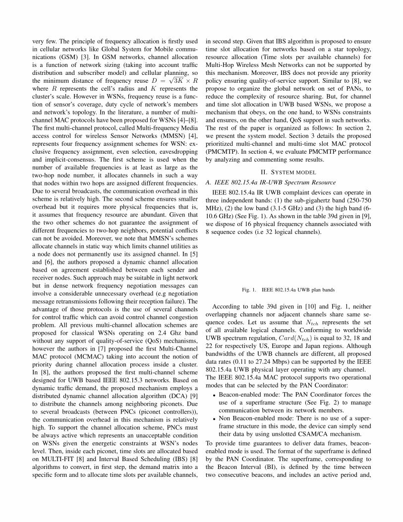
IEEE 802.15.4a IR UWB complaint devices can operate inthree independent bands: (1) the sub-gigahertz band (250-750MHz), (2) the low band (3.1-5 GHz) and (3) the high band (6-10.6 GHz) (See Fig. 1). As shown in the table 39d given in [9],we dispose of 16 physical frequency channels associated with8 sequence codes (i.e 32 logical channels).
Fig. 1. IEEE 802.15.4a UWB plan bands
According to table 39d given in [10] and Fig. 1, neitheroverlapping channels nor adjacent channels share same se-quence codes. Let us assume that Ntch represents the setof all available logical channels. Conforming to worldwideUWB spectrum regulation, Card(Ntch) is equal to 32, 18 and22 for respectively US, Europe and Japan regions. Althoughbandwidths of the UWB channels are different, all proposeddata rates (0.11 to 27.24 Mbps) can be supported by the IEEE802.15.4a UWB physical layer operating with any channel.The IEEE 802.15.4a MAC protocol supports two operationalmodes that can be selected by the PAN Coordinator:• Beacon-enabled mode: The PAN Coordinator forces the
use of a superframe structure (See Fig. 2) to managecommunication between its network members.
• Non Beacon-enabled mode: There is no use of a super-frame structure in this mode, the device can simply sendtheir data by using unslotted CSAM/CA mechanism.
To provide time guarantees to deliver data frames, beacon-enabled mode is used. The format of the superframe is definedby the PAN Coordinator. The superframe, corresponding tothe Beacon Interval (BI), is defined by the time betweentwo consecutive beacons, and includes an active period and,

optionally, a following inactive period. The active period,corresponding to the Superframe Duration (SD), is dividedinto 16 equally sized time slots, during which data trans-mission is allowed. For a global network of Nc PANs, eachPAN coordinator is characterized by its superframe duration{PANi = (SDi, BIi)}1≤i≤Nc
as shown in Fig. 3.
Fig. 2. PAN superframe structure
Fig. 3. Network configuration
During each elementary active cycle SDmin, we can shareavailable channels between only active PANs. Then, eachactive PAN coordinator must efficiently assign time slots perallocated channel to its PAN’s members. According to radiotransceiver characteristics, channel switch latency does notexceed 9.0ns (UWB devices) [8]. Although we can assumethat during one duty cycle the additional delay introduced byradio channel switch is not significant, an efficient channel-switch scheme must be proposed to avoid unnecessary channelswitches. To switch from a channel to another we just needto firstly program the set of available frequency channels ata specific register (e.g fsctrl.freq for CC2420 transceiver)then to select a given channel. This register must be set to theadequate value. Given the several advantages offered by theUWB technology, we propose to investigate the UWB physicallayer specified by IEEE 802.15.4a standard for WSNs, bydesigning efficient schemes to ensure the best managementof the UWB spectrum resource.
B. Network Topology
In order to deploy a dense network supporting a consid-erable number of nodes, we proposed in [11] a three-tierednetwork to represent the global network, using UWB sensorsin the first and second network levels. We have chosen theUWB technology for the following raisons:
• its extremely low transmitting power minimizing interfer-ence and energy consumption,
• high data rates allowing real time and high data rateapplications,
• location capacity ensuring mobility management andnode identification.
For the third tier, we propose Wifi network to benefit fromits high data rate, large coverage and security aspects. Weaim to design a WHSN (Wireless Hospital Sensor Network)for an application in hospital (medical monitoring of patientsand management of doctors). Fig. 4 shows all network layerscomposing a WHSN.
Fig. 4. WHSN architecture
The lowest level represents the Body Sensor Network(BSN). We can model an elementary BSN by a star networkcomposed of one coordinator and a set of biosensors thatensure physiological measurements and the medical moni-toring of patient. To improve patient’s network performancein a dense hospital environment, we propose overlaying thenetwork of BSNs with a second upper level network orPAN. As shown in Fig. 4, the network is represented by ahexagonal cell of sensors organized in a full mesh topol-ogy including one PAN’s coordinator, several mobile BSNscoordinators (one coordinator per BSN) and several routers.For an efficient solution for channel allocation and mobilitymanagement in WHSNs, that cellular architecture, based onUWB/Wifi technologies, is chosen to the third level to havefinally a three-tier hierarchical cellular network. The detaileddescription of the network architecture is out of scoop ofthis paper, so for more details, one can refer to [11]. Letus assume the general case of a network composed by Nc
PANs uniformly distributed. The ideal case of an hexagonalmodel is chosen to ensure the totality coverage of the network.Although in practice the coverage zone of a sensor device isneither an hexagon nor a perfect circle, there are proceduresand mechanisms [12] that ensure the adjustments of the modelduring network deployment by means of experimental test ofmeasurements. To benefit completely from advantages offeredby the UWB technology, we treated, in [13], the problem ofUWB-channels sharing between PANs and we propose, in thefollowing section, a new MAC protocol ensuring an efficient

multi-channel and multi-time slot sharing inside PANs.
III. PMCMTP FOR AN IR UWB SENSOR NETWORK
A WHSN is intended to ensure real time and continuouspatient monitoring, to reduce time of routine consultation andto immediately treat emergency cases. So, such network mustsupport a huge number of BSNs or patients with differentstates which must be monitored by means of various typesof biosensors. Consequently, the network must support QoSensuring efficient patient monitoring. In order to enhance suchQoS in terms of network capacity or throughput increase, de-lays decrease, prioritized physiological measurements support,load and energy balancing, we propose a PMCMTP for meshWSN taking into account:• Spatial channel reuse in order to efficiently assign several
channels per PAN without suffering from co-channelinterference,
• PANs duty cycle in order to dynamically allocate chan-nels and maximize channel utility,
• Data stream prioritization at the level of PANs and BSNs,to ensure QoS support per patient and per service.
A. First Level of Channels Allocation
Inside a WSN, we distingue two types of traffic: Controland data communication traffics. Control traffic is generated toidentify each PAN, to synchronize devices that are associatedwith a PAN and to manage communication between eachPAN’s members. Data communication traffic represents theuseful information to be transmitted between devices.
1) Control channel allocation: To avoid control channelcongestion [6], we propose to statically assign one controlchannel to each PAN. The emission power density of theUWB signals is less than -41.3 dBm/MHz [10]. Given that,overlapping channels (4, 7, 11 and 15) are characterized byhigh bandwidth [10], they can allow higher transmit power,permitting an extended range, compared to non-overlappingchannels. To persistently cover each cell with control traffic,we find that the overlapping channels are more suitable toensure the zone coverage for such traffic.
2) Dynamic data communication channel allocation: Ac-cording to network configuration and by means of an optimalcoloring algorithm, we propose to allocate the set of residualchannels (non-overlapping channels and the supplementaryoverlapping channels with their appropriate sequence codes)for data communication. According to PAN’s duty cycle andavailable channel frequencies, each PAN coordinator can ben-efit simultaneously from several data communication channels.The detailed description of UWB-channels (Control and datachannels) sharing between PANs is out of scoop of this paper,so for more details, one can refer to [13].
B. Second Level of Data Channels Allocation (inside a PAN)
In this subsection, we propose a method of logical channelsand time slots allocation inside each PAN. For each cycle,PAN coordinator collects all the resource allocation requestsof its network’s members. Then, according to the spectrum
sharing scheme [11], it can know the number of channels thatit can benefit from during the current active cycle. Next, ittries to allocate available time slots per channel in response tocollected requests. Finally, concerned sensors can begin theirdata communications. The principle of proposed protocol isbased on the three following phases:
1) Phase for requesting time slots,2) Phase of channels/time slots allocation,3) Phase of data transmission.• Phase for requesting time slots: Compared to MCMAC
protocol [7], PMCMTP begins with a phase of requeststransmission but it takes into account not only channelallocation task but also a dynamic time slots assignment.On the one hand, in PMCMTP, the number of requestedtime slots can vary from one transmission request toanother according to the application needs. On the otherhand, we distinguish two types of request: BSN trans-mission request (communication inside BSN) and rout-ing transmission request (communication between PAN’smembers). Transmission requests phase must precedeeach PAN’s active period. As shown in Fig. 5, this phaseis divided into two sub steps, in order to synchronizethe PAN in the first step, and to collect all transmissionrequests of concerned PAN’s members, in the second step.During this phase, the allocated control channel is used.During the first step, by listening to the beacon frame,PAN members adjust their wake-up clocks. The secondstep represents a set of equal short time slots, duringwhich, the PAN coordinator is listening to the requestsof PAN’s member. So, inside each PAN, according to thenumber of members, PAN coordinator assigns to eachmember a specific time slot according to its ID. Earliertime slot is assigned for lower ID. As shown in Fig. 5,just following the reception of the first beacon frame,each PAN’s member waits for its own time slot in orderto send its request packets.
Fig. 5. Phase of transmission requests
The request packet is composed of 7 fields (Fig. 6):– Type: Type of packet,– RqID: Request Identifier,

– Rqtype: Type of resource allocation request:∗ Rq0: For communication inside BSN,∗ Rq1: For routing communication inside a PAN.
– P: Request’s priority level,– TS: Number of required time slots,– @Source: @ of the request’s sender,– @Destination: @ of flow destination.
Type RqID Rqtype P TS @Source @Destination
Fig. 6. Request packet structure
• Phase of channels/time slots allocation: This step is trans-parent to all members of PAN except the PAN coordinatorwhich is the responsible of the execution of the relatedprocess. According to the Request Scheduling Algorithm(RSA), after reception of all transmission requests, thePAN coordinator tries to schedule it according to itsaccorded priority. Once the list of requests are scheduled,the PAN coordinator tries to launch the phase of time slotsand channels allocation. For each request, it tries to findthe earliest available time slots per channel to assign itto the suitable request. We note that for routing requeststhe coordinator must allocate resource for the entire pathfrom the source to the destination taking into accountthe stat of nodes (Busy, sleep, free) and the resourceavailability (time slots and channels). So, for each hopit tries to assign the requested time slots to the availablechannel. Also, during this phase, the coordinator tries aspossible to minimize channel switches. At the end ofthe process of time slots and channels allocation, PANcoordinator registers a trace of requests which were notserved in its queue in order to analyze it during the nextcycle. Then, it inserts into the next beacon frame thenecessary information of the served requests as shownin Fig. 7.– ACH :Index of allocated channel,– FTS: The index of the first allocated time slot,– ATS: Number of allocated time slots.
RqID ACH FTS ATS @Source @Destination
Fig. 7. Necessary information that must be added to beacon payload
• Phase of data transmission: After listening to the secondbeacon frame, PAN’s members can have a feedbackof their transmission requests. Each concerned sensorswitches to the suitable channel at the suitable time slotand it begins sending or receiving data frames duringthe accorded duration. According to Fig. 8, during syn-chronization step, PAN coordinator sends beacon frameover the accorded control channel using the mandatorydata rate (850 Kbps). During data communication phase,sensors communicate (T: Transmission, R: Reception, andBSN: BSN’s communication) using the accorded datacommunication channels.
The RSA algorithm can be better explained by following anexample. Considering the case of four resource requests
NotationRQ: Set of requests, RqFirst: A temporary set of requestsRqServed: Set of served requests, Rqinqueue: Set of requests in queueRqk
i : A resource request where k ∈ {0, 1}, Pi: Priority Level of a requestFTSi: First time slot, LTSi:Last time slot, TSi: Time slotsIDi: Identifier of request’s sender,@Si: Address of the request’s sender@Di: Address of flow destination, ATSi: First allocated time slot,ACHi: Allocated channel, Ni: Number of hops, TS/CH: TS per channels
Algorithm 1 Request Scheduling Algorithm (RSA)1. Collection of resource requests Rqk
i
RQ = {Rqki , k ∈ {0, 1}} ∪Rqinqueue
∀Rqki ∈ RQ Set FTSi = 0 and LTSi = TSi
2. Decomposition of each routing resource request Rq1iinto a set of Ni routing resource requests of one hop where:Set FTS1
i = FTSi and LTS1i = LTSi
Set FTSji = LTSj−1
i and LTSji = FTSj
i + TSi, j ∈ [2, Ni]j refers to the jth hop in the path3. Selection of more priority resource requests: RqFirst
2.a. Set RqFirst ={Rqk
i ∈ RQ where Pi = min(Pj),∀Rqkj ∈ RQ}
2.b. Set RQ = RQ−RqFirst
4. Conflict avoidance between Rqki with same priority
If ∃(Rqki , Rq
kj ) ∈ RqFirst where:
[(@Si = @Dj) or (@Di = @Dj)] and[[FTSi, LTSi] ∩ [FTSj , LTSj ] 6= ∅] Then
If (TSi < TSj) or ((TSi = TSj) and (IDi < IDj)) ThenSet FTSj = LTSi, LTSj = FTSj + TSj
5. Conflict avoidance between Rqki with different priority
If ∃(Rqki , Rq
kj ) ∈ RqFirst ∪RQ where:
[(@Si = @Dj) or (@Di = @Dj)] and[[FTSi, LTSi] ∩ [FTSj , LTSj ] 6= ∅] Then
If (Pi < Pj) ThenSet FTSj = LTSi, LTSj = FTSj + TSj
6. Schedule RqFirst where:If (FTSi < FTSj) Then Set Rqk
j after Rqki
Else If (FTSi > FTSj) Then Set Rqki after Rqk
j
Else If (TSi < TSj) or (TSi = TSj and IDi < IDj) ThenSet Rqk
j after Rqki
7. Allocation of time slots per available channelwhile (RQ 6= ∅ and TS/CH are available){
7.a while (RqFirst 6= ∅ and TS/CH are available){∀Rqk
i ∈ RqFirst
ATSi = lowest available Time slot ≥ FTSi,ACHi = index of relative channelRqFirst = RqFirst −Rqk
i
RqServed = RqServed ∪Rqki } End While
7.b repeat 2, 3, 4, 5 and 6} End While8. If RQ 6= ∅ Then Rqinqueue = RQ
(TABLE I) and three channels 0, 1 and 2 (represented byblue, green and purple colors), after the processing of received

requests, RSA allocates required time slots per availablechannels to each request as shown in TABLE II. Fig. 8illustrates synchronization and data transmission phases.
TABLE IEXAMPLE OF FOUR RESOURCE REQUESTS
RqID Rqtype P TS Source Destination Path1 1 1 2 11 13 11 → 12 →132 1 2 1 14 11 14→ 113 0 4 4 15 15 —4 0 3 2 13 13 —
TABLE IIRESOURCE ALLOCATION OF THE PREVIOUS EXAMPLE
RqID ACH FTS ATS Source Destination1 0 0 2 11 121 0 2 2 12 132 1 2 1 14 113 1 0 2 13 134 2 0 4 15 15
Fig. 8. Reception of beacon frame and beginning of data transmission
IV. PERFORMANCE EVALUATION
We have implemented PMCMTP in a discrete-time simu-lator built in JAVA and based on some functionalities definedby Prowler simulator [14] with the support of the networkarchitecture proposed in [11] and the spectrum sharing schemedetailed in [13]. In this section, we propose to evaluate theperformance of PMCMTP.
A. Simulation Parameters
Let us consider a synchronized network of 9 hexagonalcells of radius R = 5m. Each PAN has 35 nodes uniformlydistributed (One PAN coordinator, thirty routers and fourBSNs coordinators). Each PAN coordinator is characterizedby its superframe duration {PANi = (SDi, BIi)}1≤i≤9 asshown in Fig. 2 and Fig. 3. We define BImaj and SDmin asrespectively the major cycle and the elementary active cycle.
BImaj = LCM(BI1, BI2, ..., BI9) = max1≤i≤9
(2BOi)
SDmin = LCD(SD1, SD2, ..., SD9) = min1≤i≤9
(2SOi)
So, BImaj = 32, SDmin = 1.TABLE III shows the default value of each parameter in thesimulations. To eliminate the bottleneck problem of single sinknode, we assume that there are several sink nodes in each PAN.
TABLE IIISIMULATION PARAMETER
Parameter Default valueNumber of PANs, Nodes per PAN 9, 35
Communication rate 850KbpsRadio range 5m for control, 2m for data
Data Packet length 127BytesSystem Load Variable according to the number and
per elementary active cycle characteristics of resource requestsCharacteristic of resource requests P ∈ {1− 5} TS ∈ {1− 4}
Time slot duration 0.985msSOmin 4 , (PAN ’s superframe Order
will be normalized by SOmin)Routing Layer Geographic-Based Shortest Path Routing
B. Network Channel Allocation per Active Cycle
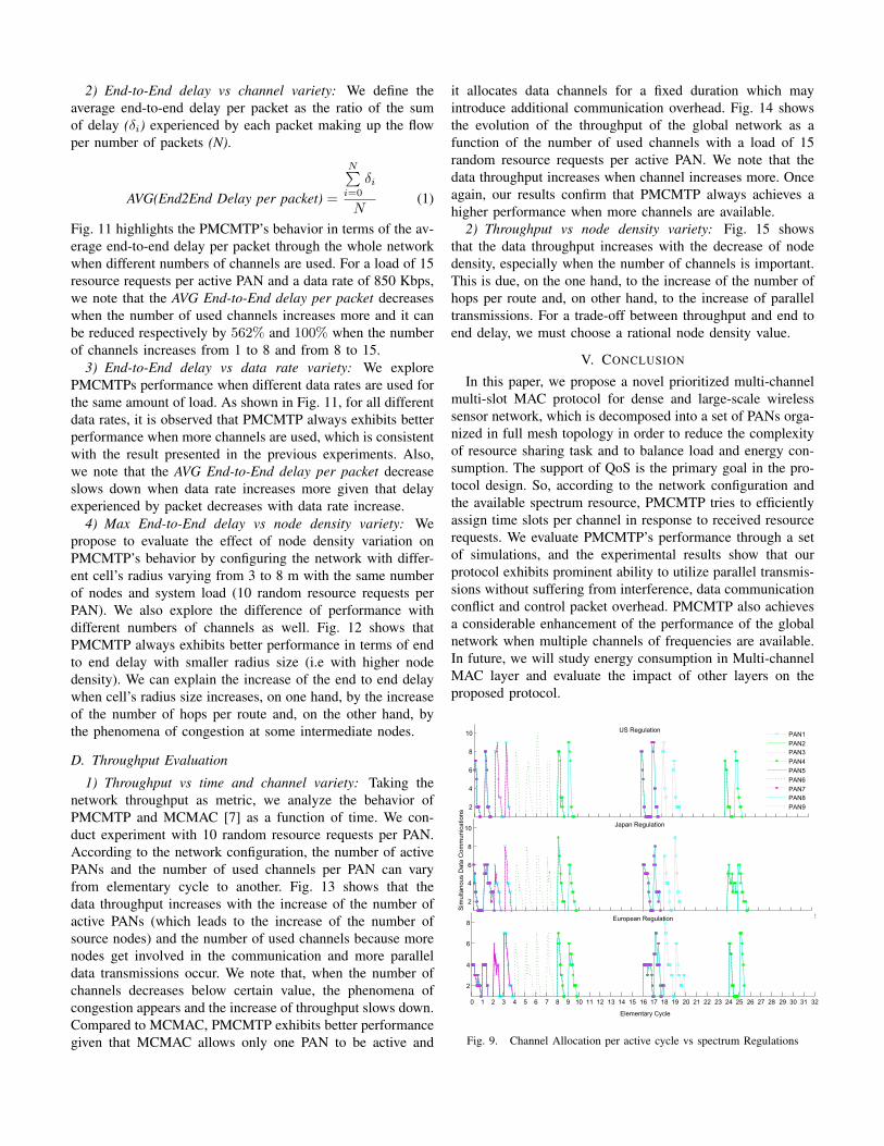
According to the network’s configuration shown in Fig. 3and channel allocation scheme detailed in [12] each PANduring its active elementary cycle can benefit from severalchannels of frequencies. As shown in Fig. 9 during the 1st,2nd and 17th elementary cycles each active PAN allows upto 4, 6 and 9 simultaneous communications respectively withEuropean, Japan and US spectrum regulation. Where duringthe 3rd, 4th, 9th, 18th and 25th elementary cycles, each activePAN benefits from 7, 9 and 14 channels respectively withEuropean, Japan and US regulation. For a load of 10 CBRper elementary active cycle per PAN, we note that each activePAN is able to simultaneously support all communicationswith Japan and US UWB spectrum regulation given thatthe number of available channels is bigger than supporteddata communications. During the 5th, 6th, 7th, 8th,10th,19th, 20th and 26th elementary cycles, active PANs benefitsimultaneously from all available channels and all independentcommunications are simultaneously served.
C. Delay Evaluation
1) Required time slots vs channel and system loads variety:We take the number of required time slots to serve a setof resource requests (5, 10 and 15 resource requests perPAN) as a metric to measure PMCMTP performance. Toanalyze performance scalability, we conduct simulation withdifferent numbers of channel frequencies as well. Fig. 10shows that, with all system loads, our protocol becomesmore time efficient when we increase the number of channelfrequencies. For this reason at the level of the global network,we impose a dynamic data channel allocation based on PANsduty cycle’s information and spatial frequency reuse to avoidthe underutilization of spectrum resource and to maximize thenumber of used channels per active PAN. We note that theamount of required time slots in the case of 5, 10 and 15resource requests decreases respectively by 3.5, 8 and 12.25times when the number of channels increases from 1 to 15.
2) End-to-End delay vs channel variety: We define theaverage end-to-end delay per packet as the ratio of the sumof delay (δi) experienced by each packet making up the flowper number of packets (N).
AVG(End2End Delay per packet) =
N∑i=0
δi
N(1)
Fig. 11 highlights the PMCMTP’s behavior in terms of the av-erage end-to-end delay per packet through the whole networkwhen different numbers of channels are used. For a load of 15resource requests per active PAN and a data rate of 850 Kbps,we note that the AVG End-to-End delay per packet decreaseswhen the number of used channels increases more and it canbe reduced respectively by 562% and 100% when the numberof channels increases from 1 to 8 and from 8 to 15.
3) End-to-End delay vs data rate variety: We explorePMCMTPs performance when different data rates are used forthe same amount of load. As shown in Fig. 11, for all differentdata rates, it is observed that PMCMTP always exhibits betterperformance when more channels are used, which is consistentwith the result presented in the previous experiments. Also,we note that the AVG End-to-End delay per packet decreaseslows down when data rate increases more given that delayexperienced by packet decreases with data rate increase.
4) Max End-to-End delay vs node density variety: Wepropose to evaluate the effect of node density variation onPMCMTP’s behavior by configuring the network with differ-ent cell’s radius varying from 3 to 8 m with the same numberof nodes and system load (10 random resource requests perPAN). We also explore the difference of performance withdifferent numbers of channels as well. Fig. 12 shows thatPMCMTP always exhibits better performance in terms of endto end delay with smaller radius size (i.e with higher nodedensity). We can explain the increase of the end to end delaywhen cell’s radius size increases, on one hand, by the increaseof the number of hops per route and, on the other hand, bythe phenomena of congestion at some intermediate nodes.
D. Throughput Evaluation
1) Throughput vs time and channel variety: Taking thenetwork throughput as metric, we analyze the behavior ofPMCMTP and MCMAC [7] as a function of time. We con-duct experiment with 10 random resource requests per PAN.According to the network configuration, the number of activePANs and the number of used channels per PAN can varyfrom elementary cycle to another. Fig. 13 shows that thedata throughput increases with the increase of the number ofactive PANs (which leads to the increase of the number ofsource nodes) and the number of used channels because morenodes get involved in the communication and more paralleldata transmissions occur. We note that, when the number ofchannels decreases below certain value, the phenomena ofcongestion appears and the increase of throughput slows down.Compared to MCMAC, PMCMTP exhibits better performancegiven that MCMAC allows only one PAN to be active and
it allocates data channels for a fixed duration which mayintroduce additional communication overhead. Fig. 14 showsthe evolution of the throughput of the global network as afunction of the number of used channels with a load of 15random resource requests per active PAN. We note that thedata throughput increases when channel increases more. Onceagain, our results confirm that PMCMTP always achieves ahigher performance when more channels are available.
2) Throughput vs node density variety: Fig. 15 showsthat the data throughput increases with the decrease of nodedensity, especially when the number of channels is important.This is due, on the one hand, to the increase of the number ofhops per route and, on other hand, to the increase of paralleltransmissions. For a trade-off between throughput and end toend delay, we must choose a rational node density value.
V. CONCLUSION
In this paper, we propose a novel prioritized multi-channelmulti-slot MAC protocol for dense and large-scale wirelesssensor network, which is decomposed into a set of PANs orga-nized in full mesh topology in order to reduce the complexityof resource sharing task and to balance load and energy con-sumption. The support of QoS is the primary goal in the pro-tocol design. So, according to the network configuration andthe available spectrum resource, PMCMTP tries to efficientlyassign time slots per channel in response to received resourcerequests. We evaluate PMCMTP’s performance through a setof simulations, and the experimental results show that ourprotocol exhibits prominent ability to utilize parallel transmis-sions without suffering from interference, data communicationconflict and control packet overhead. PMCMTP also achievesa considerable enhancement of the performance of the globalnetwork when multiple channels of frequencies are available.In future, we will study energy consumption in Multi-channelMAC layer and evaluate the impact of other layers on theproposed protocol.
0 1 2 3 4 5 6 7 8 9 10 11 12 13 14 15 16 17 18 19 20 21 22 23 24 25 26 27 28 29 30 31 32
2
4
6
8
10 PAN1
PAN2PAN3
PAN4
PAN5
PAN6
PAN7PAN8
PAN9
0 1 2 3 4 5 6 7 8 9 10 11 12 13 14 15 16 17 18 19 20 21 22 23 24 25 26 27 28 29 30 31 32
2
4
6
8
10
Sim
ulta
no
us
Da
ta C
om
mu
nic
atio
ns
0 1 2 3 4 5 6 7 8 9 10 11 12 13 14 15 16 17 18 19 20 21 22 23 24 25 26 27 28 29 30 31 32
2
4
6
8
Elementary Cycle
US Regulation
European Regulation
Japan Regulation
Fig. 9. Channel Allocation per active cycle vs spectrum Regulations

1 2 3 4 5 6 7 8 9 10 11 12 13 14 150
10
20
30
40
50
60
Number of Channels per PAN
Req
uire
d T
ime
Slo
ts
5 Requests
10 Requests15 Requests
Fig. 10. Required Time Slots vs Channel Variety
5 1 2 3 4 5 6 7 8 9 10 11 12 13 14 150
0.1
0.2
0.3
0.4
0.5
0.6
0.7
0.8
0.9
1
Number of Channels
AV
G E
nd−
to−
End
Del
ay p
er p
acke
t (m
sec)
850 Kbps
6.81 Mbps27.24 Mbps
Fig. 11. AVG End-to-End Delay per PAN vs Channel and Data rate Variety
1 2 3 4 5 6 7 8 9 10 11 12 13 14 150
0.5
1
1.5
Number of Channels
Max
End
−to
−E
nd D
elay
(m
sec)
R=3mR=4mR=5mR=7mR=8m
Fig. 12. Max End-to-End Delay vs Node Density Variety
1 2 3 4 5 6 7 8 9 10 17 18 19 20 25 260
1
2
3
4
5
6
7
8
9x 10
6
Elementary Active Cycle
Thr
ough
put (
Byt
e pe
r se
c)
PMCMTP, US Regulation
PMCMTP, Japan RegulationPMCMTP, European Regulation
MCMAC, European Regulation
Fig. 13. Throughput vs Time
1 2 3 4 5 6 7 8 9 10 11 12 13 14 150
2
4
6
8
10
12
14
16x 10
6
Number of Channels per PAN
Glo
bal T
hrou
ghpu
t (B
yte
per
sec)
Fig. 14. Throughput vs Channel Variety
1 2 3 4 5 6 7 8 9 10 11 12 13 14 150.5
1
1.5
2
2.5
3
3.5
4
4.5
5x 10
4
Number of ChannelsT
hrou
ghpu
t (B
yte
per
sec)
R=3m
R=4m
R=5mR=7m
R=8m
Fig. 15. Throughput vs Node density Variety
REFERENCES
[1] X. Wang and T. Berger, ”Spatial channel reuse in wireless sensornetworks”, Springer, vol 14, iss 2, pp. 133-146, March 2008.
[2] CC2420 datasheet, inst.eecs.berkeley.edu/ cs150/Documents/CC2420.pdf[3] X. Lagrange, P. Godlewski and S. Tabbane, ”Reseaux GSM-DCS ”,
Herms Sciences Publications.[4] G. Zhou, C. Huang, T. Yan, T. He and J. Stankovic, A. Abdelza-
her, ”MMSN: multi-frequency media access control for wireless sensornetworks”, INFOCOM 2006. 25th IEEE International Conference onComputer Communications Proceedings, April 2006, pp. 1 - 13.
[5] R.E. Cagley, S.A. McNally and M.R. Wiatt, ”Dynamic channel allocationfor dynamic spectrum use in wireless sensor networks” Military Commu-nications Conference, October 2006, pp. 1-5.
[6] H. So, W. Walrand and J. Jeonghoon, ”McMAC: a parallel rendezvousmulti-channel MAC protocol”, IEEE Wireless Communications and Net-working Conference, March 2007, pp. 334-339.
[7] X. Chen, P. Han, Q. He, S. Tu and Z. Chen,”A multi-channel MACprotocol for wireless sensor networks”, The 16th IEEE InternationalConference on Computer and Information, 2006, pp.224-229.
[8] A. Rangnekar, K.M. Sivalingam, ”Multiple Channel Scheduling in UWBbased IEEE 802.15.3 Networks”, Proceedings of the First InternationalConference on Broadband Networks, October 2004, pp.406-415.
[9] R. Prakash, N. Shivaratri, and M. Singhal, ”Distributed Dynamic ChannelAllocation for Mobile Computing”, In Proceedings of the 14 th ACMSymposium on Principles of Distributed Computing, August 1995.
[10] IEEE 802.15.4a Standard Part 15.4: IEEE Standard for InformationTechnology, Amendment to IEEE Std 802.15.4-2006, 2007.
[11] J. Ben Slimane, Y.Q .Song, A. Koubaa, M. Frikha, ”A Three-TieredArchitecture for Large-Scale Wireless Hospital Sensor Networks”, theInternational Workshop on Mobilizing Health Information to SupportHealthcare-Related Knowledge Work - MobiHealthInf 2009, pp 20-31.
[12] J. Jemai, R. Piesiewicz, T. Kurner, ”Calibration of an indoor radiopropagation prediction model at 2.4 GHz by measurements of the IEEE802.11b preamble” IEEE 61st Vehicular Technology Conference, Spring.2005,Vol 1, pp.111-115.
[13] J. Ben Slimane, Y.Q .Song, A. Koubaa, M. Frikha, ”Allocation of controland data channels for Large-Scale Wireless Sensor Networks”, Technicalreport, 2008, http://hal.inria.fr/inria-00322584/fr/.
[14] http://www.isis.vanderbilt.edu/projects/nest/prowler/.