a parametric strategy for freeform glass structures using...
TRANSCRIPT

303
A Parametric Strategy for Freeform Glass StructuresUsing Quadrilateral Planar Facets
James Glymph, Dennis Shelden, Cristiano Ceccato, Judith Mussel
Gehry Partners, LLP., Santa Monica, California, USA
Dr.-Ing. Hans Schober
Schlaich Bergermann & Partners, Stuttgart, Germany
Abstract
The design and construction of freeform glass roofing structures is generally accomplished through theuse of either planar triangular glass facets or curved (formed) glass panes. This paper describesongoing research on the constructability of such structures using planar quadrilateral glass facets for theJerusalem Museum of Tolerance project by Gehry Partners, in collaboration with Schlaich Bergermann& Partners, engineers. The challenge here lies not only in the development of a geometric strategy forgenerating quadrilateral planar facet solutions, but also in the fact that said solutions must closely matchthe designs created initially in physical model form by the architects.
We describe a simple but robust geometric method for achieving the structure by incorporating thenecessary geometric principles into a computational parametric framework using the CATIA Version 5system. This generative system consists of a hierarchical set of geometric ‘control elements’, that drivethe design toward constructible configurations. Optimization techniques for approximating the generatedstructural shape to the original created by the designers are also described. The paper presents theunderlying geometric principles to the strategy and the resulting computational approach.
1 Introduction
The design for the Jerusalem Museum of Tolerance (referred to in this paper as MOT), a project of theSimon Wiesenthal Center, is currently under development at Gehry Partners. This voluminous complexis a multifunctional group of building components, each of which is given unique design character withinthe context of the overall design (Figure 1). A major component of the project is a series of large,freeform glass structures, that are the subject of discussion in this paper. Seven glass surface structuresare used, including some functioning as walls. The two largest segments cover a large space formed bya curved Museum building and two other components, the Grand Hall and the Research Center, andwere the subjects of the initial investigations described in this paper.
Resolving these glass structures is a twofold problem: first, it is a problem of computational geometryand resulting implications for fabrication; second, it is a problem of user interaction and design methods.The latter problem is of particular importance, because Gehry Partners has developed a very specificway of working with regard to how designs are created and developed, and how the computer supportsthis process. Finding a viable geometrical solution mechanism that fits into this framework is paramountin ensuring that the generated forms reflect the original design intention.

ACADIA 2002
Figure 1. The Museum of Tolerance Project, aerial view
2 From Physical Models to Digital Mockups
Over the past 10 years, Gehry Partners (formerly Frank O. Gehry & Associates) has developed a set ofunique working methods centered on the concept of the “Master Model”. In the context of Frank Gehry’swork, the firm uses the computer as a design development and design production tool: in other words,the computer is used to capture a formal design intention and make it constructible (Figure 2).
Within the Gehry studio, the designs produced by Frank Gehry working with two senior designers aredeveloped by a set of dedicated design teams. This design intent is developed primarily in a sculpted,physical model form. The “Master Model” surface geometries are created through acquisition of 3Dgeometrical information from the physical models by means of a 3D spatial scanner arm (Figure 3). Thescan process yields a constructive data point set from which then-matching 3D computer geometry isdeveloped. This ensures an accurate representation of the design intent within the computer, while atthe same time allowing the data to be manipulated as required to yield constructible geometricsolutions.
Figure 2. The Museum of Tolerance CATIA V5 Master Model

Parametric Strategy for Freeform Glass Structures
Glymph / Shelden / Ceccato / Mussel / Schober 305
Figure 3. Data acquisition from physical models
Once the framework for a given project is in place, in terms of programmatic requirements, form andlayout, an initial computer model is built. The model is continuously refined during the designdevelopment process. Over time, the computer model acquires a large amount of information thatmakes the Master Model into an integrated, three-dimensional database of project information that isconsidered the digital mockup of the project. For a more-detailed discussion of the core technologiesused at Gehry Partners, see Lindsey (2001) and Mitchell (2001).
3 The Problem: Free-Form Faceted Glass Structures
Gehry Partners and Schlaich Bergermann & Partner have successfully collaborated in the past on thesolution of complex form glass roof systems, notably on the DG Bank building in Berlin (Figure 4). Onthat project, the central atrium space was covered by a longitudinally symmetrical glass structure built oftriangular planar glass facets. The adoption of this strategy for the MOT project proved unfeasible,mainly because the sheer economy of scale generated by the quantity and dimensions of glass surfacestructures (roofs and some lateral enclosure elements).
Figure 4: The DG Bank Berlin atrium roof

ACADIA 2002
Figure 6. Basic geometric principle for planar quadrangular mesh
sectional curvesectional curve
longitudinal edge lateral edge
(a) (b)
Although triangulated surfaces can describe any freeform shape, employed in construction they areeconomically less advantageous than equivalent surface structures built of quadrilateral (four-sided)facets: Quadrangular mesh constructions require fewer machining operations on the glass, and fewermullions (as they eliminate the diagonal mullion from one side of the triangle). However, this achievedeconomy of scale can only be maintained if the quadrilateral facets of the surface structure aremaintained planar: the cost of single- or double-curved glass facets would immediately void the premisefor a quadrilateral solution.
There are, however, geometric principles that can guarantee the geometric planarity of facets in aquadrangular mesh system, using translation surfaces. Gehry Partners leveraged Schlaich Bergermann& Partner’s experience to use this method on the MOT project.
4 Translation Surface Structures: Basic Geometric Principles
Quadrangular-meshed nets may be used to describe any double-curved surface, but usually thequadrangles of the surface are not planar (Figure 5). In the following section, simple methods arepresented for creating an almost unlimited multitude of shapes for double-curved surfaces with planarquadrangles.
Figure 5. Quadrangular mesh of a double curved surface
One method is based on the simple principle that two spatial, parallel vectors are always defining aplanar quadrangular surface. The vectors and the connection between their points of origin and endpoints make up the edge of the quadrangular surface. This is not the only method - but a rather simpleone - because a planar surface may also be defined by two vectors not running parallel to each other.
Assuming one direction of the quadrangular-meshed net to be the sectional curve with its individualsections being the lateral edges, and assuming the other direction with its individual sections being thelongitudinal edges and regarding the two lateral resp. longitudinal edges as vectors, there results twodesign principles for plane quadrangular mesh:
a) The longitudinal edges of a row of mesh form parallel vectors (Figure 6a)
b) The lateral edges of a row of mesh form parallel vectors (Figure 6b).

Parametric Strategy for Freeform Glass Structures
Glymph / Shelden / Ceccato / Mussel / Schober 307
4.1 The longitudinal edges of a row of mesh form parallel vectors
Any spatial curve may be chosen as sectional curve - it does not have to be plane. The parallel vectorsgenerate the initial row of mesh (Figure 6a). The new sectional curve is the line between the end pointsof the vectors. The following row of mesh is generated according to the same principle, but of coursethe vectors here could have a different direction and length than the previous ones, thus adding one rowto the next. Almost any shape consisting of trapezoidal mesh is possible. An analytical description of theresulting surfaces is omitted here because, following the procedure described above, these surfaces areeasily generated with CAD.
To obtain homogenous structures, analytical curves can be used to develop the sectional curves andthe direction of the vector. If, for example, the sectional curve is plane and all vectors of the longitudinaledges have the same length, the result will be the design principle of the translation surface which playsa major role in the practical application.
4.2 A special application: The Translation Surface
As published already in Schober (1994) and (2002), translation surfaces permit a vast multitude ofshapes for grid shells consisting of quadrangular planar mesh.
Translating any spatial curve (generatrix) against another random spatial curve (directrix) will create aspatial surface consisting solely of planar quadrangular mesh (Figure 7). Parallel vectors are thelongitudinal and lateral edges. Subdividing the directrix and the generatrix equally results in a grid withconstant bar length and planar mesh.
If, for example, one parabola (generatrix) translates against another parabola (directrix) perpendicular toit, the result will be an elliptical paraboloid with an elliptic layout curve. Two identical parabolas generatea rotational paraboloid with a circular layout curve (Figure 8). Innovative shapes can be created byadding translation surfaces (Figure 9).
Figure 7. Geometric principle for translation surfaces
directrix
generatrix

ACADIA 2002
Figure 8. Translational surface covering an elliptical (top left) or circular plan
Figure 9. Joining of translational surfaces
Figure 10. Hyperbolic paraboloid as translational surface(left) and joining possibilities (right)
Figure 11. Translation surface covering two semi-circular plans connected withtangential edges.

Parametric Strategy for Freeform Glass Structures
Glymph / Shelden / Ceccato / Mussel / Schober 309
A directrix curving anticlastically to the generatrix results in a hyperbolic paraboloid, which can also beformed by two systems of linear generatrices (Figure 10). This allows for the creation of hypar-surfaceswith straight edges which are easy to store and can be joined in a variety of combinations (Figure 10). Alayout of two circles connected by their tangents can be covered by a translation surface consisting oftwo rotational paraboloids with a hypar-surface in between (Figure 11). All these examples consist of agrid with constant bar length and planar mesh.
This paper presents only the basic possibilities. A greater variety in shapes is described in Schober(1994).
4.3 The lateral edges of a row of a mesh form parallel vectors
Any – not necessarily linear – spatial curve can be selected as sectional curve. The new sectional curvewill be generated by parallel translation of its lateral edges, resulting in a new vector of these edges. Itsrandomly chosen length determines the shape of the new sectional curve, which is not similar to theprevious one (Figure 12). The longitudinal edges of the plane quadrangular mesh are determined by theline between the points of origin and the end points of the respective lateral edge vectors.
The next row of mesh will be created following the same principle, with the shape of the new sectionalcurve depending on the length of the lateral edges. Thus, row after row is generated and any shape withplane trapezoidal mesh is possible.
To obtain homogenous structures, the parallel vectors of the lateral edges can be developed fromanalytical curves by centric or excentric expansion or by equidistant parallels. For example, the centricexpansion of a sectional curve results in surfaces with homogenous, longitudinal edges resp. taperingrows of mesh. These surfaces obtained by scaling a translation surface are called in this paper scale-trans-surfaces.
To avoid extreme concentration the number of longitudinal edges may be reduced by setting the vectorlength to zero, if necessary (Figure 12).
4.4 A Special Application: Scale-Translation Surfaces
The centric expansion of any sectional curve yields a new one with parallel edges (Figure 13). Thecenter of expansion may be chosen at random. Centric expansion causes each lateral edge vector ofthe sectional curve to lengthen or shorten by the same factor, while maintaining its direction. Thus, fromthe (n)th sectional curve evolves the similar (n+1)th sectional curve which is then spatially translated –although without rotation – to any given spot (Figure 14). The longitudinal edges are determined by theline between the points of origin and the end points of the respective lateral edge vectors. The next rowof mesh will be created following the same principle with the shape of the new sectional curvedepending on the selected expansion factor. In this way row after row is generated.

ACADIA 2002
Figure 12. Reduction of longitudinal edges by introducing a triangular element (right)
centric expansion excentric expansion
Figure 13. Expanding a curve centrically or eccentrically results in parallel lateral edges
expansion + translation
Figure 14. Surfaces with plane quadrangular meshes are generated by expansion and translation.
Figure 15. Surface composed of plane quadrangular mesh generated by centrical expansion and translation(scale-trans surfaces)

Parametric Strategy for Freeform Glass Structures
Glymph / Shelden / Ceccato / Mussel / Schober 311
Figure 18. "Trajectory dome" covering a square plan with plane quadrangular mesh
sectional curve
centric
Translating the center of expansion
in vertical direction
Figure 17. Expansion of a random curve and vertical translation of the curve
Figure 16. Expansion of an elliptical curve and translation of the curve along a spatially curveddirectrix
directrix
directrix
Sectional curve

ACADIA 2002
To obtain homogenous structures, analytical curves such as circles, ellipses, hyperbolas or polynomialscan be divided equally (identical lateral edge length) and expanded centrically. Translating the center ofexpansion of the resulting sectional curves along an analytical spatial curve (generatrix), and adjustingthe translation distance to the expansion factor, results in homogenous surfaces with longitudinal edgesof the same length in each mesh and lateral edges of the same length in each sectional curve. Figure15 shows a double-curved surface with plane quadrangular mesh, created by centrically expandingelliptical curves and translating the center of expansion along a spatially curved directrix. Figure 16describes a sectional curve consisting of two adjoining elliptical curves. The sectional curve in Fig. 17 iscomposed of randomly chosen curves.
The "trajectory dome" in Figure 18 is created by centric expansion of a spatially curved generatrix andtranslation along a defined edge curve. The result is a dome with plane quadrangular mesh over asquare plan! Sectional curves evolving from a circle with the center of expansion in the circle's centerand are then translated along a straight directrix create a special application, the rotational surface(Figure 19). Translating these curves along a curved directrix yields a totally different surface with planequadrangular mesh. This illustrates the multitude of shapes that are possible with this procedure.
4.5 A special application: Equidistant sectional curves
In some instances it might be more advantageous to generate the new sectional curve by equallytranslating the individual lateral edges instead of using centric expansion. In this case the points oforigin and the end points of the lateral edge vectors are on the bisector of the plane sectional curve(Figure 20). Again, the lines between the points of origin and the end points of the respective lateraledge vector produce the longitudinal edges. The next row of mesh will be created following the sameprinciple. The resulting sectional curves may be translated at random or along an analytical spatialcurve (directrix).
Figure 20. In the case of equidistant curves the lateral edges meet in the bisector
Figure 19. Rotational surface as a special application of centrically expanded circularcurves
Parametric Strategy for Freeform Glass Structures
Glymph / Shelden / Ceccato / Mussel / Schober 313
4.6 Reference Projects by Schlaich Bergermann und Partner
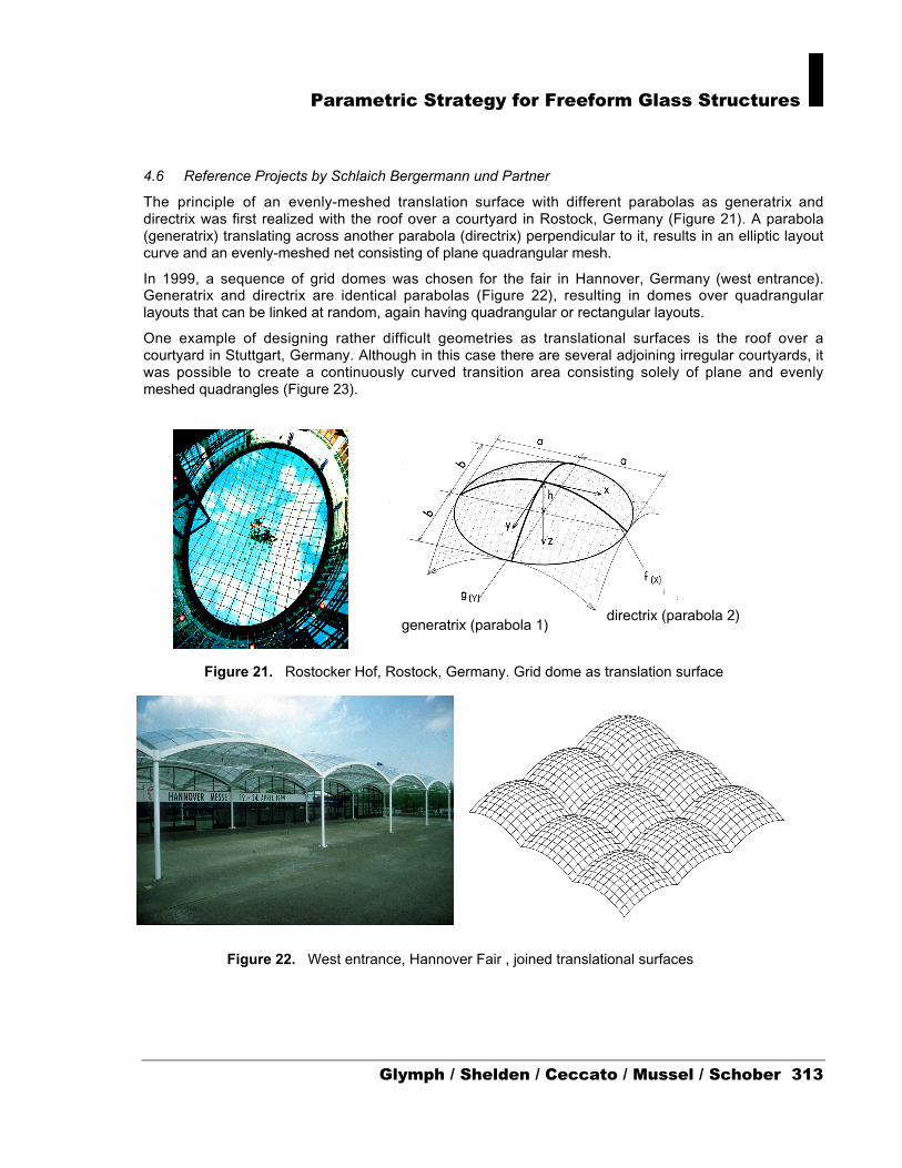
The principle of an evenly-meshed translation surface with different parabolas as generatrix anddirectrix was first realized with the roof over a courtyard in Rostock, Germany (Figure 21). A parabola(generatrix) translating across another parabola (directrix) perpendicular to it, results in an elliptic layoutcurve and an evenly-meshed net consisting of plane quadrangular mesh.
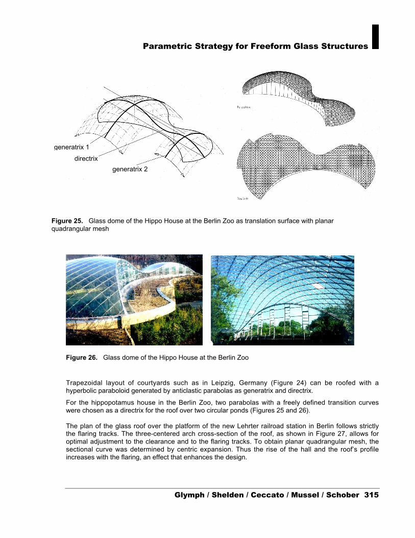
In 1999, a sequence of grid domes was chosen for the fair in Hannover, Germany (west entrance).Generatrix and directrix are identical parabolas (Figure 22), resulting in domes over quadrangularlayouts that can be linked at random, again having quadrangular or rectangular layouts.
One example of designing rather difficult geometries as translational surfaces is the roof over acourtyard in Stuttgart, Germany. Although in this case there are several adjoining irregular courtyards, itwas possible to create a continuously curved transition area consisting solely of plane and evenlymeshed quadrangles (Figure 23).
generatrix (parabola 1)directrix (parabola 2)
Figure 21. Rostocker Hof, Rostock, Germany. Grid dome as translation surface
Figure 22. West entrance, Hannover Fair , joined translational surfaces

ACADIA 2002
Figure 24. Courtyard roof Industriepalast, Leipzig, Germany
Figure 23. Courtyard roof of the former Bosch Area, Stuttgart, Germany, grid dome as translationalsurface with planar mesh
Parametric Strategy for Freeform Glass Structures
Glymph / Shelden / Ceccato / Mussel / Schober 315
Figure 26. Glass dome of the Hippo House at the Berlin Zoo
Trapezoidal layout of courtyards such as in Leipzig, Germany (Figure 24) can be roofed with ahyperbolic paraboloid generated by anticlastic parabolas as generatrix and directrix.
For the hippopotamus house in the Berlin Zoo, two parabolas with a freely defined transition curveswere chosen as a directrix for the roof over two circular ponds (Figures 25 and 26).
The plan of the glass roof over the platform of the new Lehrter railroad station in Berlin follows strictlythe flaring tracks. The three-centered arch cross-section of the roof, as shown in Figure 27, allows foroptimal adjustment to the clearance and to the flaring tracks. To obtain planar quadrangular mesh, thesectional curve was determined by centric expansion. Thus the rise of the hall and the roof’s profileincreases with the flaring, an effect that enhances the design.
Figure 25. Glass dome of the Hippo House at the Berlin Zoo as translation surface with planarquadrangular mesh
generatrix 2
directrix
generatrix 1

ACADIA 2002
5 Implementation
5.1 Parametric Associative Modeling
The beginning of the Design Development phase of the MOT project coincided with the introduction atGehry Partners of the new CATIA platform, Version 5 (currently Release 8). CATIA V5 differs from theprevious V4 in a great number of ways, presenting improvements in ease of use, interactivity andcompatibility. The greatest difference is that V5 is a fully parametric associative modeling system, andcan be greatly controlled by harnessing its associative capabilities by means of built-in scriptableintelligence features known as KnowledgeWare.
This coincidence has proven fortuitous, because V5 has allowed us to program the necessary rules andconstraints into CATIA that are necessary to generate translation surfaces that will guarantee planar,quadrilateral facets. Programming here is not intended literally as ‘coding instructions’, though the resultis the same. Rather it is the ability to embed logical constraints, directives and effectors into the modelwhile it is being built. Consequently, any changes made on the completed model are only possiblewithin the framework of these constraints that control the “translationalness” of the surface structure; inother words, any shape possible that can be generated by the constrained model is guaranteed to be atranslation surface because of the rules and constraints that control it. In short, programming in thesense of CATIA V5’s capabilities can be understood as a means of imbuing a design with controlfeatures that correspond, conceptually, to an implementation of the notion of spatial programming ordesign structuring.
5.2 Structuring of the Model
The sequence of creating such models has been relatively conceptually straightforward, thoughnavigating the meanders of CATIA V5’s complex feature set and associative hierarchy system hasproven a challenge at times. Because the system records every element created as part of a semanticlogical specification tree, it is possible to continue referencing and controlling each geometric element ofthe model as it is developed. In other words, geometry within the model is constructed as a function ofother pieces of geometry previously placed, with the associative relation being maintained in thespecification tree. Any changes thus made to geometric elements upstream in the tree immediatelytrigger an ‘update’ or re-configuration in those derived downstream. Furthermore, it is possible to embedinto the model numerical and logical parameter values that can be used to control the geometry, andcan be linked to the knowledge features described above to produce a reconfigurable intelligent modelthat permits controlled manipulation of the geometry within the constraint sets placed on it.
Figure 27. Platform roof of the Lehrter railroad station in Berlin. Plane quadrangular glasspanels obtained by centric expansion and translation of the sectional curves
Parametric Strategy for Freeform Glass Structures
Glymph / Shelden / Ceccato / Mussel / Schober 317
For the MOT glass roof structures, we used the scaled translation surface structure described in section4.4 in order to be able to match the translation surface as closely as possible to the original designedshape. The resulting parametric model was in fact relatively straightforward. It was built in the samelogical sequence used to geometrically determine the translation surface geometry:
I. Three sets of control points are created for three control curves:
a. Generatrix
b. Directrix
c. Scaling curve (Law)
Curve (c) is a spline curve used to uniformly control the scaling in the scaled translation surface.CATIA can read numeric values off curves as a ‘law’ function that can be used, as parameters, todrive other functions – in the case the scaling of the translated curves over the directrix.
II. The generatrix, directrix and law curves are created over the control point sets.
III. Two distance parameters G and D are used to control the spacing of vertices in the U and Vdirections on the translation surface.
IV. Equidistant points are placed on the directrix at D distance intervals using Euclidean (sphericalabsolute) spacing to ensure equal length for each mullion line.
V. The generatrix is translated over the equidistant points on the directirx; at each translation, thegeneratrix curve is also scaled by a value S read from the law curve at the correspondentabscissa value on the length of the law curve reference.
VI. Equidistant points are placed on the translated and scaled generatrix curves at (G*S) scaleddistance intervals using Euclidean (spherical absolute) spacing to ensure equal length for eachmullion line on each specific generatrix curve.
5.3 Control of the Translation Surface Structure
Control of the surface is achieved by combining a combination of any of the following:
I. Modifying the control points for the directrix curve.
II. Modifying the control points for the generatrix curve.
III. Modifying the control points for the law (scaling) curve.
IV. Modifying the D and G distance parameter values.
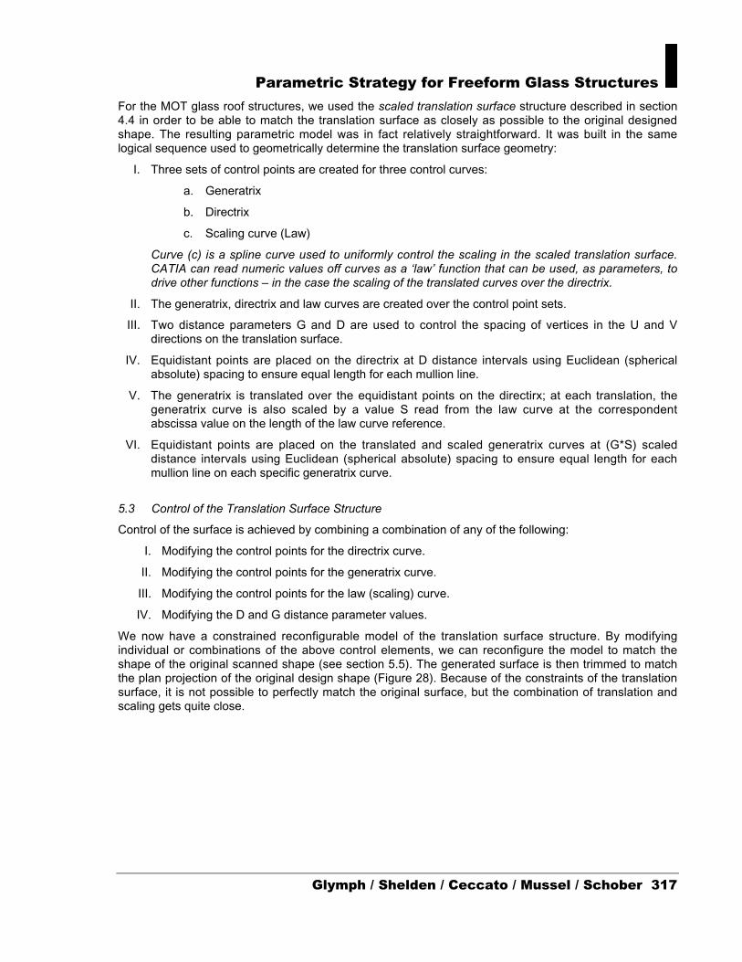
We now have a constrained reconfigurable model of the translation surface structure. By modifyingindividual or combinations of the above control elements, we can reconfigure the model to match theshape of the original scanned shape (see section 5.5). The generated surface is then trimmed to matchthe plan projection of the original design shape (Figure 28). Because of the constraints of the translationsurface, it is not possible to perfectly match the original surface, but the combination of translation andscaling gets quite close.
ACADIA 2002
Figure 28: Parametric-associative model showing original scanned surface from physical model (darkblue), generatrix and directrix curves, and trimmed generated translation surface (violet).
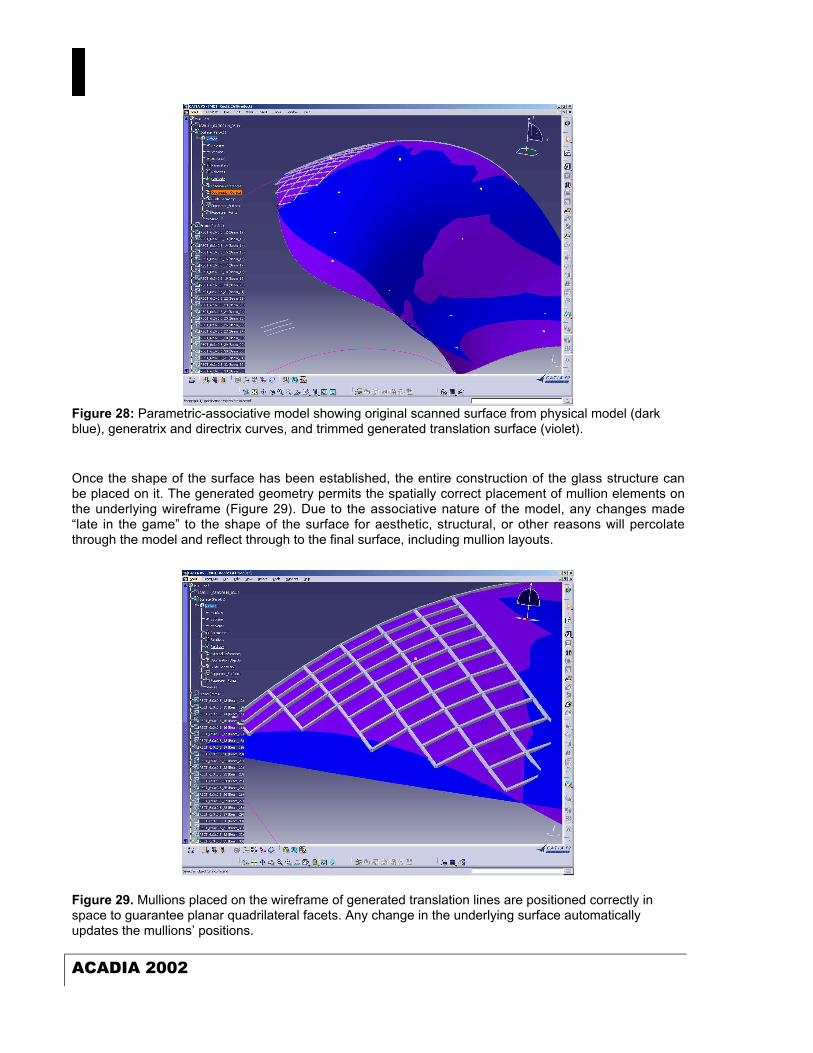
Once the shape of the surface has been established, the entire construction of the glass structure canbe placed on it. The generated geometry permits the spatially correct placement of mullion elements onthe underlying wireframe (Figure 29). Due to the associative nature of the model, any changes made“late in the game” to the shape of the surface for aesthetic, structural, or other reasons will percolatethrough the model and reflect through to the final surface, including mullion layouts.
Figure 29. Mullions placed on the wireframe of generated translation lines are positioned correctly inspace to guarantee planar quadrilateral facets. Any change in the underlying surface automaticallyupdates the mullions’ positions.

Parametric Strategy for Freeform Glass Structures
Glymph / Shelden / Ceccato / Mussel / Schober 319
5.4 Automation and Geometric Correctness
The generation of the geometric and topological requirements for a translation surface structure can becomputationally automated such that, by selecting the appropriate input elements (normally the controlelements listed in section 5.3), the system can automatically generate the entire parametric structurewhich, by definition, guarantees true translation surface conformity. One can conceive of this approachas a kind of automated ‘translation surface template’.
5.5 Form-finding Processes
As we have seen, we can structure a reconfigurable model that contains, by its definition, the rules andconstraints that make a translation surface. In other words, once the structure is in place, it still must be‘shaped’, using the control elements described in section 5.3 to approximate as closely as possible theoriginal surface created in model form by the designers.
This form-finding process itself presents a number of options, depending on where one sees the actualdesign event occurring. If we assume that the design of the shape in question has been completed inmodel form, then the entire process described in this paper is nothing other than a mechanistic solutionfor the construction of said shape. However, because a design process is in fact more complex andcyclical, then one could assume that even after the translation structure has been parametricallymodeled, modifications can still occur that can substantially affect the actual form.
In the Gehry studio, revisions are constantly made to the designs in physical model form, either foraesthetic, programmatic or – in the case of the glass structures – for structural reasons. For example,substantial modifications to the designers’ approach in determining their shape had to be made, in orderto ensure greater degrees of curvature in the surface that would ensure structural feasibility without,say, the need for external support elements such as columns.
Manual form-finding: The directrix and generatrix curves can be modified to ‘tweak’ the surface intoconforming to the original, as can the scaling ‘law’ curve. Interestingly, we have found that, to a veryhigh degree, human intuition is a substantial factor in this method. Determining, for example, the startingconfigurations for directrix and generatrix in such a way that they produce very close configuration fromthe outset is a qualitative judgment that comes as much from experience with the project in hand as itdoes from the user’s CAD modeling abilities.
One scenario that has been explored at Gehry Partners is the designer working directly on theparametric model with the CAD operator: the designer can make changes ‘live’ to the model. Commentssuch as ‘can you make it a little more curved here’ or ‘flatter there’ can be translated directly into thestructure’s form by manipulating the control elements on-the-fly.

ACADIA 2002
Figure 30: Optimization techniques can be used to approximate the form of the generated translationsurface (yellow) to that of the original scanned surface (blue) by minimizing the distance betweencorresponding sampled surface points.
Computational form-finding: If we assume that no modifications are made to the model’s shape, thenone could enable the computer to automatically approximate, as closely as possible, the translationstructure to the original form (Figure 30). This can be done through the application of search methods,such as Simulated Annealing or Linear Hill-climbing, or nonlinear techniques such as GeneticAlgorithms. Regardless of the method, the search mechanism continues to modify the controlparameters while measuring the resulting conformity of the surface to the original design shape.
6 Conclusions
Using CATIA Version 5 enabled us to clarify the procedures necessary for implementing free-formpanelized structures using translation surface geometries. Parametric/associative infrastructure,combined with constraint-solving capabilities, allow for the structuring of design concepts early; as wellas for controlling design development tool further downstream. Furthermore, by combining thetechniques described in sections 5.4 and 5.5, we can see the parametric model as a kind of machinethat is capable of producing translation surface structures in response to a particular set of inputs.
In conclusion, it could be stated that parametric associative models are also a design refinement tool aswell as a design development and production tool. By embedding logical control features andconstraints into the model, and using its capabilities for controlled user interaction, the user can takeadvantage of the parametric and associative features of the model to refine a design within the contextof the logic structured within the model.
Parametric Strategy for Freeform Glass Structures
Glymph / Shelden / Ceccato / Mussel / Schober 321
7 Bibliography
Holgate, A. (1997). The Art of Structural Engineering: The Work of Jörg Schlaich and his Team.Stuttgart, Germany: Edition Axel Menges.
Lindsey, B. (2001). Digital Gehry. Princeton, NJ: Princeton Architectural Press 2001.
Mitchell, W.J. (2001). Roll Over Euclid: How Frank Gehry Designs and Builds. In Ragheb, J.F., Ed.,Frank Gehry, Architect, pp. 353-363. New York: Guggenheim Museum Publications.
Schober, H. (1994). Die Masche mit der Glaskuppel. In Deutsche Bauzeitung No. 128, October 1994,pp. 152-163. Stuttgart and Bonn, Germany: Deutsche Verlagsanstalt/BDA.
Schober, H. (1999). Glass Roofs and Glass Facades. In Behling, S. and Behling S., Eds., Glass:Structure and Technology in Architecture. Munich, Germany: Prestel Verlag.
Schober, H. (2002). Geometrie-Prinzipien für wirtschaftliche und effiziente Schalentragwerke. InBautechnik No. 79, January 2002, pp. 16-24.

ACADIA 2002