a new approach for generating facility · pdf filenearly equal to the traditional reference...
TRANSCRIPT
1
A NEW APPROACH FOR GENERATING FACILITY
LAYOUTS USING AN ALGORITHMIC APPROACH
Christian Mosblech
Chair of Materials Handling and Warehousing
Faculty of Mechanical Engineering
TU Dortmund University
Dortmund, Germany
Volker Sadowsky
Chair of Materials Handling and Warehousing
Faculty of Mechanical Engineering
TU Dortmund University
Dortmund, Germany
Abstract
In this paper a new approach is described to automatically create
layouts for material flow systems. The current research in progress aiming
at adopting the methods and algorithms of the Electronic Design
Automation to be used in logistics planning is presented. These methods
are already applied to create microchips being multiple times more
complex than material flow systems while following the same goal:
Functional units have to be placed on a predefined area and are linked by
connections weighted differently. This basic requirement can be applied to
microchip designs as well as material flow systems. The common
condition is to create the setup with the smallest connection length
possible.
The results are compared to a currently applied computerized method
to calculate facility layouts. The overall result of the introduced method is
nearly equal to the traditional reference method to create a computerized
material flow layout. However, while the new algorithm does all
calculations automatically, the traditional method requires manual
finishing to achieve a comparable result.
This article thereby shows the potential of the research in progress
toward the goal to support logistics planning with a new generation of
automated software tools.
2
1 Introduction
Creating an optimized facility layout for a material flow system is one of the main tasks
in almost every planning process. These processes are structured and organized by
different methods and strategies splitting the overall process into multiple single steps.
One of those is always the creation of a layout having an optimized material flows ([1],
[2], [3]). Although creating a material flow layout is included in all these planning
methods, the tools and algorithms actually used are not on the level of the current
research and technical possibilities. Basic algorithms like CRAFT ([4]) or heuristics like
the triangle generation of Schmigalla ([5]) are originated in the last century. This includes
the adaption of these heuristics to the computerized resources available back then. Since
this technology has strongly advanced, the layout algorithms have concurrently been
further optimized without implementing a completely new approach. Thereby, the
available potential of the current computer generation including additional features like
parallel processing, huge amounts of physical and virtual storage capacity and the raw
processing power is not fully utilized by the existing layout generation algorithms.
The use of such resources allows efficient processing of large amounts of data as
included in the tasks of intralogistics planning. In order to satisfy customer demands like
decreasing the number of units while increasing their level of individuality, the
complexity of logistics systems has been escalating in the past years. Logistic processes
have to be more flexible resulting in shortened planning periods for creating new or
evolving existing systems. Under such circumstances manual planning processes are too
time consuming while they take up days or weeks whereas the considered systems have
to react within merely hours on changing determining factors. According to current
research the future logistics and production systems will be modular to a certain degree (
[6, 7, 8]). This makes changes to the whole system on a just-in-time basis depending on
customer orders possible. Therefore, planning results especially in the field of layout
generation are required to be available on short notice. Alternatively, the monetary
advantages of those modular systems can be erased by rising costs for the material
handling.
The general goal is to develop a highly automated method to create possible layouts
to a given material flow system. In the best case the ongoing research in this field of
expertise will lead to a system to generate optimal material flow layouts at the push of a
button. The means to describe such a system are chosen in accordance to the commonly
used tools and data representations in the logistics planning process such as transportation
matrices or area specifications for material flow components.
This article presents the results of an ongoing research project and presents the first
breakthroughs made. It describes the fundamental mathematical problem to be solved by
a layout generation process. This description is followed by an overview of heuristics to
solve the layout creation processes currently in use. Additionally, the shortcomings of
current methods are highlighted. This enumeration shows the requirement for creating a
new approach for the layout generation with an easy to use and easy to understand

3
approach on the one hand and the possibility to create optimal layouts in a short time on
the other hand. This new approach is introduced in the subsequent part of this article. The
method makes use of the research results in another field of work having the same
fundamental problem on a larger scale: the Electronic Design Automation (EDA). This
field combines the methods and algorithms to create complex digital circuits placed on a
microchip. After presenting basic process model of the EDA, the first implementations
and adaptions into intralogistics planning are brought forward. After first promising
validations, this article closes with the perspective on further research work in this area.
2 Basic Problem
The general problem while creating a material flow layout is aiming for an optimal
material flow while using the minimal amount of space possible with all components
placed. Additionally, there are multiple more determining factors raising the complexity
of the general calculation even further. These factors can range from obvious ones like
prohibiting overlaps during the planning process to complex legal regulations e. g. in the
field of chemical production or the food industry. One of the most common goals of the
facility layout is to minimize the transport costs required for the material flow system to
work properly ([9]).
Creating a valid layout for a material flow system shall be described as a
mathematical problem. This problem is defined as the Factory Layout Problem (FLP)
described in the following formula:
∑∑
with
: number of components in the material flow system
: the material flow between the components and
: the cost for the transport between components and
: the distance between the components and ([2, 9])
To create a valid layout only the matrix containing all distances is optimized
while the other influences are untouched. Those parts of the formula originated from the
project data pool or their values are the result of decisions within the planning process
like the conveying system to be deployed. Solving the mathematical problem however
results in either long calculation times or imprecise outcomes depending on the algorithm
used.
Another constraint to this fundamental solution is the absence of additional
conditions to the calculation. For example, placing two functional units directly besides
each other is only a random outcome based on the overall material flow and cannot be
controlled by the input parameters. The requirement to do so can be shown by an obvious
4
example, like placing the incoming goods process of an intralogistics system near the
delivery gates of the facility. Without defining the special connection between these two
components explicitly, the placement is only depending on the transport intensity in
between.
These shortcomings have led to different solutions currently applied in logistics
planning processes being presented thereafter.
3 Current Practices and Research
Currently there are multiple methods and algorithms available allowing the creation of
layouts for intralogistics and production systems. One possible classification of these
methods can be achieved by focusing on the required calculations enabling a manual
planning or involving computerized support. Additionally, there are recent developments
solving the fundamental problem with completely new approaches.
3.1 Manual planning procedures
Manual planning methods enable the planner to create viable layouts within a short
period of time. Normally these methods solve the general problem to create a facility
layout in early planning stages. The most basic solutions require the planner to produce
models of the material flow components from paper or cardboard and place them inside a
given area. This approach is supported by modern CAD software applications by
allowing creating the placement virtually. Some advances have been made using
heuristics structuring this manual placement process. Two of those are the friction circle
method by Schwerdtfeger and triangular method by Schmigalla ([5, 10]).
In contrast to the simple means to create layouts with these methods there are several
disadvantages, such as the required amount of time, the lack of precision and the
disability to cope with determining factors directly. These shortcomings make sure that
the manual procedures are mostly used in a very early planning stage. They are not able
to create layouts sophisticated enough to be directly implemented. In case of the
triangular method, they are unable to handle loops in the material flow. Additionally,
these procedures depend strongly on the expertise of the executing planner. Without
knowledge and expertise, creating a material flow layout resembles trial and error and
does not follow an organized and structured pattern.
3.2 Automated planning algorithms
The algorithms in this group make use of computerized resources to create layouts for
material flow systems. Therefore, these methods can calculate layouts more efficiently
creating results nearer to the optimal solution for a given facility layout task. Their
central advantage is making use of the capability to calculate numerous equations
simultaneously enabling even trial and error based algorithms or the complete
5
enumeration of potential solutions for small material flow systems to be executed in a
short amount of time.
One of the first algorithms being developed is the Computerized Relative Allocation
of Facilities Technique (CRAFT) algorithm. It was originated in the 1960s and was first
described in [11] by G. C. Armour and E. S. Buffa. Basically this method cuts given
functional units into parts having the size of a pre-defined rectangular pattern. Following
an initial placement setup is created by guessing a valid layout result. In the actual
calculation phase the algorithms tries to find pairs of components reducing the overall
transportation cost if exchanged. If such a pair is discovered, all involved parts are
exchanged.
The CRAFT algorithm in its basic form has one main disadvantage. It may not be
able to keep the rectangular form of the material flow components during the runtime.
This originates from the exchange of functional units with unequal sizes. To create
enough free space for the larger exchange partner, a noninvolved third component has to
be modified. Because only so many parts are moved as required to place the exchanged
unit, this can lead to the dissolving of the original rectangular form. This can lead to "L"-
or "T"-shaped placement propositions. Besides, by exchanging parts of the element after
these have been cut to the minimal possible raster size can lead extreme aspect ratios. In
the worst case this can result to valid layouts concerning the minimal material flow which
are impossible to implement in the real world. An example is the placement of an
automated store and retrieval system on an area of two meters by 100 meters. Even
creating one aisle between two shelves is not possible.
Regardless of these shortcomings, the basic CRAFT algorithm has been the origin
for further research. These attempts tried to improve results or the calculation duration or
even to overcome the known problems of the basic algorithm ([12, 13]). However, this
research does not change the fact that the algorithm was created to run on mainframe
computers having been state of the art in the early 1960s. Modern computer systems have
not only increased the amount of possible calculations per second resulting in a faster
calculation, but also technologies like parallel processing have been introduced with the
repetitive exchange of functional units being not able to gain from them.
3.3 Recent Research results
In the last decade additional research aimed to solve the facility layout problem by using
completely new ways. Methods having been developed, which are adopting models from
fields of research different to the intralogistics in order to solve the fundamental problem.
Promising results are published using a Taboo-Search algorithm on slicing trees, a co-
evolutionary algorithm or even mapping the fundamental problem to an ant-colonization
optimization [9, 14, 15]. Even transferring production and material flow systems to the
metabolism of cells is currently in research and the creation of optimal layouts can be one
of the possible outcomes [16].

6
All these methods are no longer comprehensible in detail for the planner and require
solemnly advanced computer systems to function. Possible occurring errors cannot be
traced easily, especially if there are already inconsistencies in the input data to the
calculations.
3.4 Research gap
Each mentioned method or algorithm has shortcomings limiting its respective use. Not
one of the algorithms or heuristics is able to cope with the claimed requirements modern
layout generation dictates to the planner. The creation of layouts for material flow or
production systems has to be created nearly instantaneously making use of data
commonly available to a logistics planner. This allows modern intralogistics systems to
be optimized according to their flexibility and modularity.
4 New Approach
The fundamental problem of placing components on a predefined area or at least within
the smallest amount of occupied space can be found in other fields of work besides
intralogistics planning. In some of these, the considered problems exceed the facility
placement by far in terms of size and connection complexity. One solution to the
fundamental placement problem can be found in the field of Electronic Design
Automation (EDA).
EDA is a name for the algorithms and applications enabling the creation of modern
integrated circuits ([18]). Due to the number of components contained on one
microprocessor, manual designing is not possible. In 2011 NVIDIA Corp. claimed to
have placed 3.0 billion transistors on a single GPU ([19]). While the complexity of
modern microchips has not stopped increasing since and the technologies to produce such
devices become more and more sophisticated, the transistor count is increasing
nowadays. This characteristic of a microchip is even used as an indicator for the
complexity and capabilities of the embedded circuits.
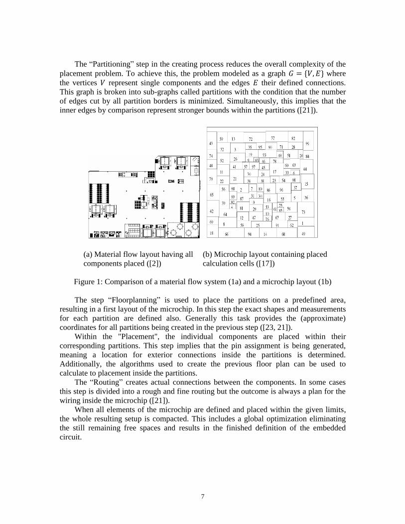
Figure 1 shows an example for a material flow system (figure 1a) and a microchip
design (figure 1b) obviously showing the similarities in the placement. Simultaneously,
this example hints at the increased complexity of creating a valid and optimized
microchip layout. The microchip contains a placement for a higher component count than
the shown material flow system.
4.1 Basic Modeling Process
The basic process to create a microchip layout has no single definition. The implemented
methods vary in their structures and details ([20], [21], [22]). There are similarities
however, resulting in five basic steps leading to a microchip layout. These steps are
displayed in figure 2.
7
The “Partitioning” step in the creating process reduces the overall complexity of the
placement problem. To achieve this, the problem modeled as a graph where
the vertices represent single components and the edges their defined connections.
This graph is broken into sub-graphs called partitions with the condition that the number
of edges cut by all partition borders is minimized. Simultaneously, this implies that the
inner edges by comparison represent stronger bounds within the partitions ([21]).
(a) Material flow layout having all (b) Microchip layout containing placed
components placed ([2]) calculation cells ([17])
Figure 1: Comparison of a material flow system (1a) and a microchip layout (1b)
The step “Floorplanning” is used to place the partitions on a predefined area,
resulting in a first layout of the microchip. In this step the exact shapes and measurements
for each partition are defined also. Generally this task provides the (approximate)
coordinates for all partitions being created in the previous step ([23, 21]).
Within the "Placement", the individual components are placed within their
corresponding partitions. This step implies that the pin assignment is being generated,
meaning a location for exterior connections inside the partitions is determined.
Additionally, the algorithms used to create the previous floor plan can be used to
calculate to placement inside the partitions.
The “Routing” creates actual connections between the components. In some cases
this step is divided into a rough and fine routing but the outcome is always a plan for the
wiring inside the microchip ([21]).
When all elements of the microchip are defined and placed within the given limits,
the whole resulting setup is compacted. This includes a global optimization eliminating
the still remaining free spaces and results in the finished definition of the embedded
circuit.

8
Figure 2: Basic process to create a microchip design
The central task for the current research is to map the input, the determining factors
and the outcome to intralogistics systems. This includes the creation of analogies for
every single component used in the process as well as implementing simplifications to
the overall procedure. An example to reduce the complexity is the possibility to use one
conveyor system to transport multiple goods while a placed wire inside a microchip can
only deliver one single signal.
As this article describes current research in progress only the first process steps in
the EDA setup have been implemented so far.
4.2 Adopting Partitioning
There are two different types of algorithms solving the partitioning problem. The first
group creates two sets of nodes on a given graph using different optimization
methods after creating an initial guess. Thereby these algorithms are limited to an output
of two partitions. Every other solution has to be calculated by running the algorithm on
the results of a prior run creating two new partitions on each generated set. This leads to
an optimal partitioning only in the case, if the required number of partitions is included in
the sequence . Elsewise the resulting partitions vary in size. Examples for such
algorithms are Kernighan-Lin or Fiduccia-Mattheyses ([24, 25]).
The second type of algorithms creates partitions simultaneously, whereat the
value is specified by the user. The created partitions are about the same size and again the
internal edges represent stronger bonds than the external ones. To calculate the optimal
set of these partitions there are two possible approaches. On the one hand the basic bi-
partitioning algorithms are modified to cope with more than two partitions [26]. On the
other hand a spectral analysis of the eigenvectors of the matrix derived from the material
flow graph can be used to create the optimal partitioning [27, 28].
In addition, the graph representation of a material flow system is augmented by
adding values to the edges resulting in a graph with weighted edges ( ) . The added term ( ) is used to assign a real value to every edge in the graph. The
function maps the transports intensities of the material flow system to the edges in the
corresponding graph representation. In contrast to the original algorithms the transports
between material flow components can differ regarding their intensity. At the same time,
9
this function can be used to evaluate the cuts created by partitioning the material flow
graph. The task of the partitioning algorithms is therefore modified. It searches for the
partitioning cutting the smallest sum of transport intensities instead of the smallest
number of connections. This creates partitions with strong internal material flows while
all streams to other partitions are smaller by direct comparison.
Both ways to calculate partitions have been reviewed to find the best solution for
partitioning material flow systems. Coping with multiple or weighted connections is not
possible in every case and calculating the eigenvectors to a degree of requires a vast
amount of calculation time. A compromise between calculation efficiency and accuracy
is introduced by [29, 30]. In the proposed algorithm a helpful set is calculated from
eigenvectors and used as a base for the exchange heuristic of Kernighan-Lin. Tests have
determined that this algorithm is able to handle the common data sizes of material flow
systems while creating optimal partitions.
4.3 Implementing the Floorplanning
The floorplanning step uses algorithms to place the prepared partitions on a user defined
area. There are several ways to create these placements. One possibility is the use of
slicing trees introduced in 1983 ([31]). This method to place components on a defined
area is already applied onto intralogistics systems ([9]). Other ways to create floor plans
are the cluster-growth-algorithm ([21]) or the linear order algorithm ([32]).
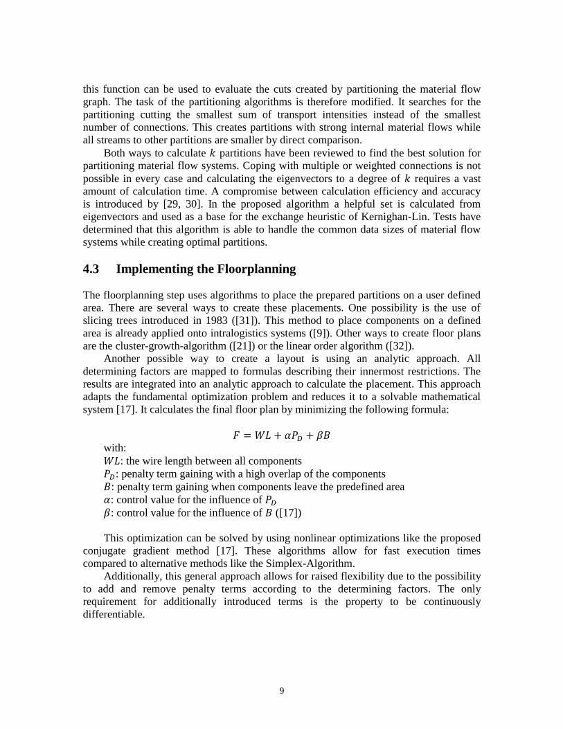
Another possible way to create a layout is using an analytic approach. All
determining factors are mapped to formulas describing their innermost restrictions. The
results are integrated into an analytic approach to calculate the placement. This approach
adapts the fundamental optimization problem and reduces it to a solvable mathematical
system [17]. It calculates the final floor plan by minimizing the following formula:
with:
: the wire length between all components
: penalty term gaining with a high overlap of the components
: penalty term gaining when components leave the predefined area
: control value for the influence of
: control value for the influence of ([17])
This optimization can be solved by using nonlinear optimizations like the proposed
conjugate gradient method [17]. These algorithms allow for fast execution times
compared to alternative methods like the Simplex-Algorithm.
Additionally, this general approach allows for raised flexibility due to the possibility
to add and remove penalty terms according to the determining factors. The only
requirement for additionally introduced terms is the property to be continuously
differentiable.
10
5 First validation Results
The first two steps of creating a layout using the methods of the Electronic Design
Automation have been successfully mapped to intralogistics planning and implemented
as a software application. In the process the required input data has been adopted to fit
commonly used description forms for material flow systems. The resulting software
application creates a graph representing the system internally, if at least provided with a
transportation matrix. Using this material flow graph, partitions can be calculated and the
values of the necessary cuts can be optimized. This optimization can be configured to
focus on two aspects: Being executed aiming at the best overall execution time or at
creating the calculation of an optimal material flow. If the execution time is to be
optimized, the partitions are chosen to balance the calculations of the floorplanning and
the partitioning steps. This approach aims at nearly equal runtimes concerning the two
steps. If the material flow is optimized, the partition set with the smallest external
connection count has to be calculated resulting in the strongest interconnected material
flow components to be placed in short distance to each other. This means the partitioning
is done in the most efficient way concerning the material flow.
In order to calculate the second step, the dimensions of the included functional units
have to be determined. These values are developed in the planning process, for instance
by determining the capacity of the storage system or calculating the required order
picking performance.
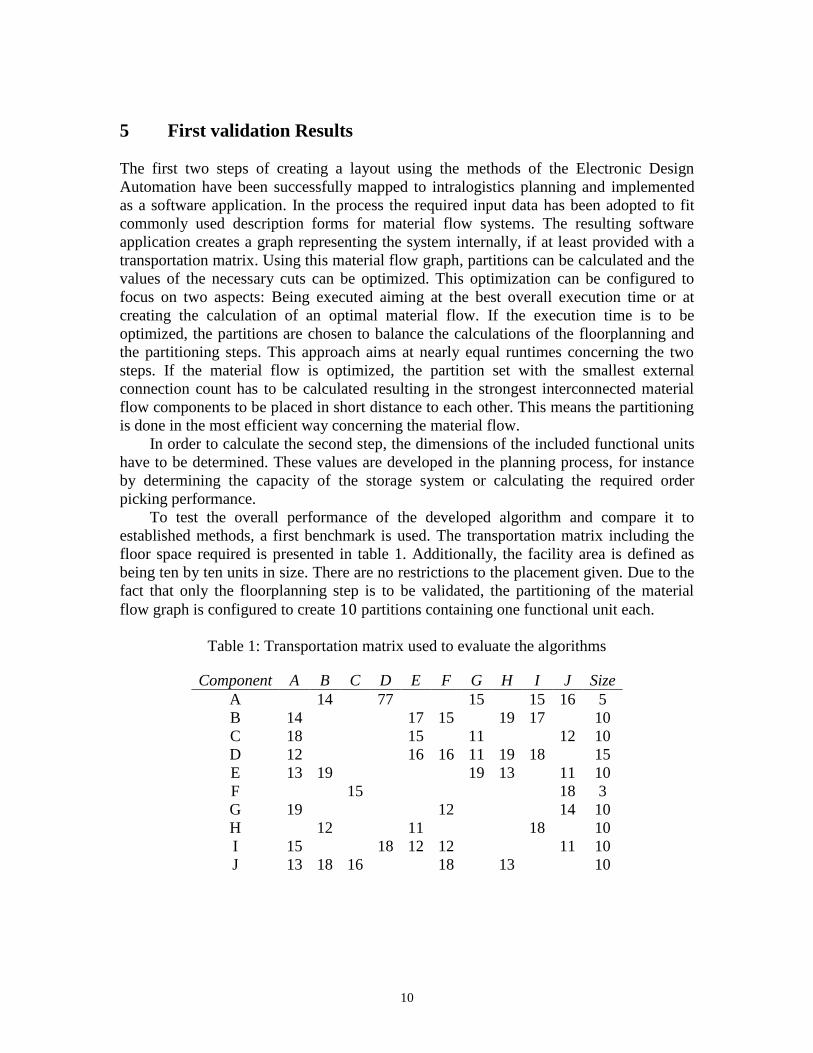
To test the overall performance of the developed algorithm and compare it to
established methods, a first benchmark is used. The transportation matrix including the
floor space required is presented in table 1. Additionally, the facility area is defined as
being ten by ten units in size. There are no restrictions to the placement given. Due to the
fact that only the floorplanning step is to be validated, the partitioning of the material
flow graph is configured to create partitions containing one functional unit each.
Table 1: Transportation matrix used to evaluate the algorithms
Component A B C D E F G H I J Size
A 14 77 15 15 16 5
B 14 17 15 19 17 10
C 18 15 11 12 10
D 12 16 16 11 19 18 15
E 13 19 19 13 11 10
F 15 18 3
G 19 12 14 10
H 12 11 18 10
I 15 18 12 12 11 10
J 13 18 16 18 13 10
11
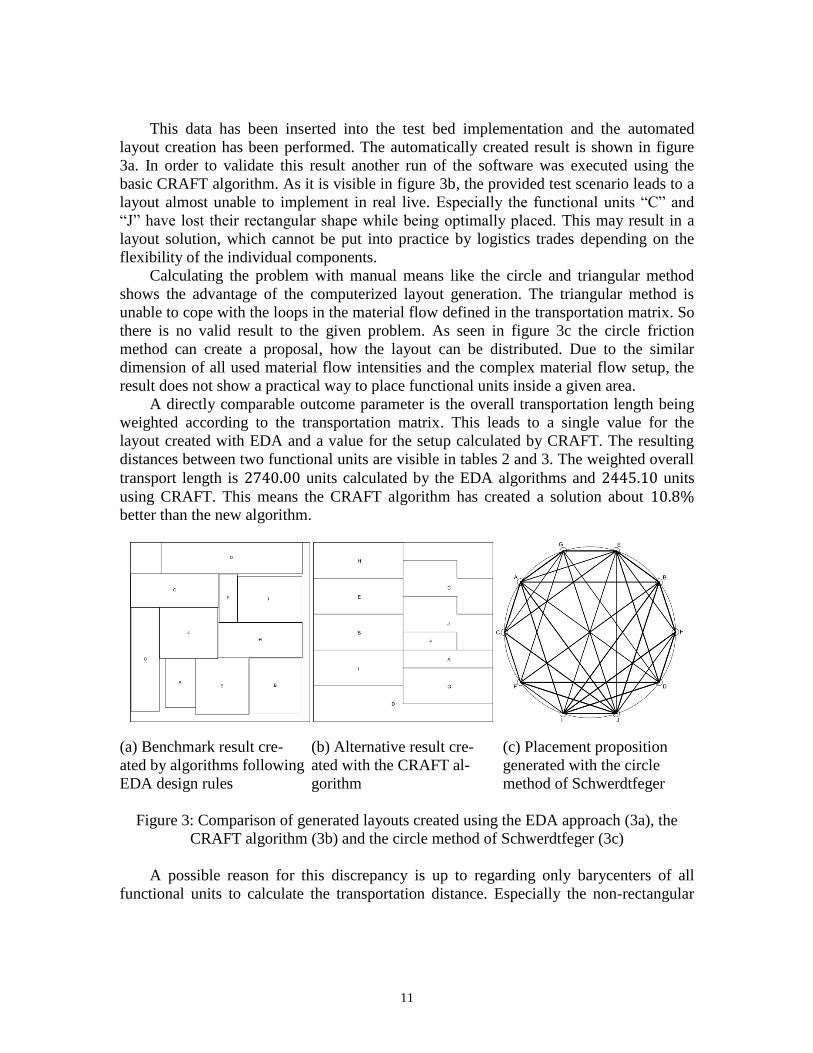
This data has been inserted into the test bed implementation and the automated
layout creation has been performed. The automatically created result is shown in figure
3a. In order to validate this result another run of the software was executed using the
basic CRAFT algorithm. As it is visible in figure 3b, the provided test scenario leads to a
layout almost unable to implement in real live. Especially the functional units “C” and
“J” have lost their rectangular shape while being optimally placed. This may result in a
layout solution, which cannot be put into practice by logistics trades depending on the
flexibility of the individual components.
Calculating the problem with manual means like the circle and triangular method
shows the advantage of the computerized layout generation. The triangular method is
unable to cope with the loops in the material flow defined in the transportation matrix. So
there is no valid result to the given problem. As seen in figure 3c the circle friction
method can create a proposal, how the layout can be distributed. Due to the similar
dimension of all used material flow intensities and the complex material flow setup, the
result does not show a practical way to place functional units inside a given area.
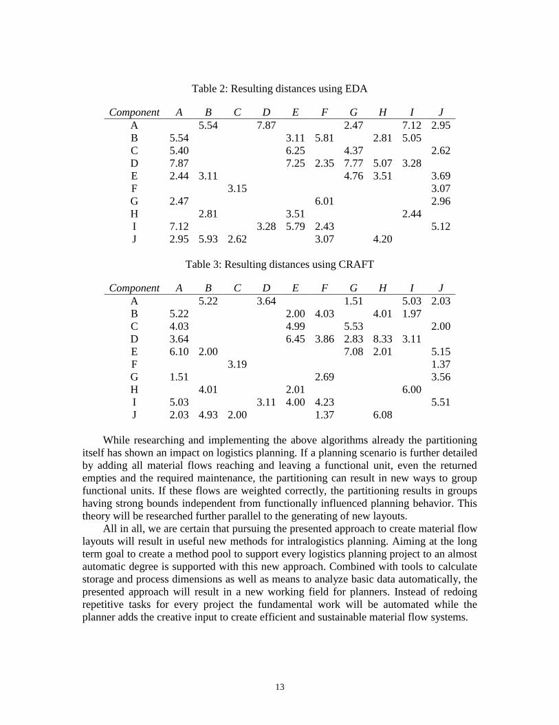
A directly comparable outcome parameter is the overall transportation length being
weighted according to the transportation matrix. This leads to a single value for the
layout created with EDA and a value for the setup calculated by CRAFT. The resulting
distances between two functional units are visible in tables 2 and 3. The weighted overall
transport length is units calculated by the EDA algorithms and units
using CRAFT. This means the CRAFT algorithm has created a solution about
better than the new algorithm.
(a) Benchmark result cre- (b) Alternative result cre- (c) Placement proposition
ated by algorithms following ated with the CRAFT al- generated with the circle
EDA design rules gorithm method of Schwerdtfeger
Figure 3: Comparison of generated layouts created using the EDA approach (3a), the
CRAFT algorithm (3b) and the circle method of Schwerdtfeger (3c)
A possible reason for this discrepancy is up to regarding only barycenters of all
functional units to calculate the transportation distance. Especially the non-rectangular
12
shapes have focal points better suited for this kind of distance calculation. Additionally, a
systematic influence resulting from the single scenario being better suited for the CRAFT
solving strategy is possible. If the CRAFT result is manually mapped to rectangle shaped
functional units, the resulting length elongates to units being only
difference to the new approach.
Although the first benchmarks resulted in a slightly raised transportation intensity
compared to traditional planning methods, the overall potential of the new way to create
layouts is obvious. Due to its mathematical approach, new restrictions can be applied
solemnly by adding corresponding penalty terms to the minimization formula. This
results in a raised flexibility concerning its use in the process of planning material flow
systems. This advantage will be balancing the slightly longer transport. Additionally, the
used calculation algorithms can be optimized in itself to create better results.
6 Conclusion and further Work
The results presented in the article show the potential benefits for the planning of
intralogistics systems. The required amount of time and the expertise needed to create a
facility layout supporting an optimal material flow can be reduced compared to the
manual realization. Additionally, already in the presented first examples, problems with
the old creation methods like sticking to rectangular shapes can be overcome.
While further pursuing the current research, the creation of material flow layouts
with the algorithms used in the field of Electronic Design Automation can result in a
software application allowing for almost automatic layout generation. It can propose
layouts optimal to the provided data and restrictions for the planner to choose from. The
calculations used to create the layouts will be optimized in further research to reach a
higher quality within reduced execution time.
Additionally, further automated benchmarks will be implemented and calculated. A
collection of material flow systems applicable as such benchmarks is defined in [9]
including the results and detailed execution data. If succeeding in creating layouts for all
given benchmarks, the new method has to compete against manual planning of
experienced planners. Real planning projects will be taken into account and the created
placements compared to the calculated results of the software.
In the next implementation step, the detailed placement and wiring algorithms have
to be implemented. This enables the resulting software not only to generate layouts, but
also to calculate the material flow paths simultaneously. This includes the actual
conveyor paths which replace the virtual distance measuring from the central point of one
component to another. This will create a completely new paradigm in the automated or
computer aided planning: While the common methods only create layouts, the EDA
algorithms provide the means to calculate placements and their connections in form of
wiring in one process. To define analogies between single point-to-point connections and
transportation systems allowing multiple reuses is the challenge in these next steps.
13
Table 2: Resulting distances using EDA
Component A B C D E F G H I J
A 5.54 7.87 2.47 7.12 2.95
B 5.54 3.11 5.81 2.81 5.05
C 5.40 6.25 4.37 2.62
D 7.87 7.25 2.35 7.77 5.07 3.28
E 2.44 3.11 4.76 3.51 3.69
F 3.15 3.07
G 2.47 6.01 2.96
H 2.81 3.51 2.44
I 7.12 3.28 5.79 2.43 5.12
J 2.95 5.93 2.62 3.07 4.20
Table 3: Resulting distances using CRAFT
Component A B C D E F G H I J
A 5.22 3.64 1.51 5.03 2.03
B 5.22 2.00 4.03 4.01 1.97
C 4.03 4.99 5.53 2.00
D 3.64 6.45 3.86 2.83 8.33 3.11
E 6.10 2.00 7.08 2.01 5.15
F 3.19 1.37
G 1.51 2.69 3.56
H 4.01 2.01 6.00
I 5.03 3.11 4.00 4.23 5.51
J 2.03 4.93 2.00 1.37 6.08
While researching and implementing the above algorithms already the partitioning
itself has shown an impact on logistics planning. If a planning scenario is further detailed
by adding all material flows reaching and leaving a functional unit, even the returned
empties and the required maintenance, the partitioning can result in new ways to group
functional units. If these flows are weighted correctly, the partitioning results in groups
having strong bounds independent from functionally influenced planning behavior. This
theory will be researched further parallel to the generating of new layouts.
All in all, we are certain that pursuing the presented approach to create material flow
layouts will result in useful new methods for intralogistics planning. Aiming at the long
term goal to create a method pool to support every logistics planning project to an almost
automatic degree is supported with this new approach. Combined with tools to calculate
storage and process dimensions as well as means to analyze basic data automatically, the
presented approach will result in a new working field for planners. Instead of redoing
repetitive tasks for every project the fundamental work will be automated while the
planner adds the creative input to create efficient and sustainable material flow systems.
14
Acknowledgements
The project funding of the presented research is provided by the EUROPEAN
UNION - European Regional Development Fund (ERDF), the Ziel2.NRW-Program and
the department “Ministerium für Wirtschaft, Energie, Industrie, Mittelstand und
Handwerk des Landes Nordrheinwestfalen”.
References
[1] ten Hompel, M., Schmidt, T. and Nagel, L., Materialflusssysteme - Förder- und
Lagertechnik, Springer-Verlag Berlin Heidelberg (2007).
[2] Arnold, D. and Furmans, K., Materialfluss in Logistiksystemen, Springer Heidelberg
Dordrecht London New York (2009).
[3] M. Heinecker, Methodik zur Gestaltung und Bewertung wandelbarer
Materialflusssysteme, Ph.D. dissertation, Technische Universität München (2006).
[4] Buffa, E. S., Armour, G. C. and Vollmann, T. E., “Allocating facilities with CRAFT,”
Harvard Business Review, 42, 2, 136-158 (1964).
[5] Schmigalla, H., Methoden zur optimalen Maschinenanordnung, VEB Verlag
Technik, Berlin (1970).
[6] Buchholz, S., “Future manufacturing approaches in the chemical and pharmaceutical
industry”, Chemical Engineering and Processing: Process Intensification, 49, 10,
993-995 (2010).
[7] Follert, G., Margareta, L., and ten Hompel, M., “Design Approach to Create
Transformable Material Flow Systems,” Sustainability and Collaboration in Supply
Chain Management, 299-308, Josef Eul Verlag GmbH, Lohmar-Köln (2013)
[8] Nopper, J., Follert, G., and ten Hompel, M., “Gains in the life-cycle of adaptable,
self-organized material handling systems,” International Material Handling Research
Colloquium (IMHRC) - Proceedings, 11, 122-132 (2010)
[9] Scholz, D., Innerbetriebliche Standortplanung - Das Konzept der Slicing Trees bei
der Optimierung von Layoutstrukturen, Gabler Verlag, Springer Fachmedien
Wiesbaden GmbH (2010).
15
[10] Kettner, H., Schmidt, J. and Greim, H.-R., Leitfaden der systematischen
Fabrikplanung, Hanser Fachbuchverlag (1984).
[11] Armour, G. C. and Buffa, E. S., “A heuristic algorithm and simulation approach
to relative location of facilities,” Management Science, 9, 2, 294-309 (1963).
[12] Bozer, Y. A., Meller, R. D. and Erlebacher, S. J., “An improvement-type layout
algorithm for single and multiple floor facilities,” Management Science, 40, 7, 918-
932 (1994).
[13] Grajo, E. S., “Strategic layout planning and simulation for lean manufacturing a
layout tutorial”, in Proceedings of the 27th Conference on Winter Simulation, 510-
514 (1995).
[14] Dunker, T., Radons, G. and Westkämper, E., “A coevolutionary algorithm for a
facility layout problem,” International Journal of Production Research, 41, 3479-
3500 (2003).
[15] Komarudin and Wong, K. Y., “Applying ant system for solving unequal area
facility layout problems,” European Journal of Operational Research, 202, 3, 730 -
746 (2010).
[16] Becker, T., Parallels between manufacturing systems in industrial production and
metabolic systems in biological cells, Jacobs University (2012).
[17] Zhan, Y., Feng, Y. and Sapatnekar, S. S., “A fixed-die floorplanning algorithm
using an analytical approach,” ASP-DAC '06 Proceedings of the 2006 Asia and South
Pacific Design Automation Conference, 771-776 (2006).
[18] Scheffer, L., Lavagno, L. and Martin, G. (Eds.), EDA for IC System Design,
Verification, and Testing, Taylor & Francis Group, LLC (2006).
[19] NVIDIA Corporation, Nvidia geforce gtx 590 graphics card datasheet, online,
(2011)
[20] Wang, L.-T., Chang, Y.-W. and Cheng, K.-T. T. (Eds.), Electonic Design
Automation: Synthesis, Verification, and Test, Morgan Kaufmann Publishers (2009).
[21] Lienig, J., Layoutsynthese elektronischer Schaltungen - grundlegende
Algorithmen für die Entwurfsautomatisierung, Springer, Berlin (2006).
[22] Jansen, D. (Ed.), The Electronis Design Automation Handbook. Springer
Science+Business Media New York (2003).
16
[23] Lengauer, T., Combinatorial Algorithms for Integrated Circuit Layout, Teubner
Verlag (1992).
[24] Kernighan, B. W. and Lin, S., “An efficient heuristic procedure for partitioning
graphs,” Bell System Technical Journal, 49, 291-307 (1970).
[25] Fiduccia, C. M. and Mattheyses, R. M., “A linear-time heuristic for improving
network partitions,” ACM IEEE Nineteenth Design Automation Conference
Proceedings (1982).
[26] Larsson Träff, J., “Direct graph -partitioning with a kernighan-lin like heuristic,”
Operations Research Letters, 34, 6 (2006).
[27] Alpert, C. J., Kahng, A. B. and Yao, S.-Z., “Spectral partitioning with multiple
eigenvectors,” Discrete Applied Mathematics, 90, 1-3, 3-26 (1999).
[28] Spielman, D. A. and Teng, S.-H., “Spectral partitioning works: Planar graphs and
finite element meshes”, Linear Algebra and its Applications, 421, 2-3, 284-305
(2007).
[29] Diekmann, R., Monien, B. and Preis, R., “Using helpful sets to improve graph
bisections,” Technical Report, Forschergruppe No. 8. AMS, 57-73 (1995).
[30] Diekmann, R., Lüling, R., Monien, B. and Spräner, C., “Combining helpful sets
and parallel simulated annealing for the graph-partitioning problem,” Parallel
Algorithms and Applications, 8, 61-84 (1996).
[31] Stockmeyer, L., “Optimal orientations of cells in slicing floorplan designs,”
Information and Control, 57, 2-3, 91-101 (1983).
[32] Kang, S., ”Linear ordering and application to placement,” Proceedings of the 20th
Design Automation Conference, 457-464 (1983).