research laboratory computerized generation and simulation ... · research laboratory computerized...
TRANSCRIPT
NASA/CR—2001-210893 ARL-CR-468 U.S. ARMY
M~W\JM RESEARCH LABORATORY
Computerized Generation and Simulation of Meshing of Modified Spur and Helical Gears Manufactured by Shaving
Faydor L. Litvin, Qi Fan, Daniele Vecchiato, and Alberto Demenego University of Illinois at Chicago, Chicago, Illinois
DISTRIBUTION STATEMENT A Approved for Public Release
Distribution Unlimited
20010611 075
May 2001
The NASA STI Program Office ... in Profile
Since its founding, NASA has been dedicated to the advancement of aeronautics and space science. The NASA Scientific and Technical Information (STI) Program Office plays a key part in helping NASA maintain this important role.
The NASA STI Program Office is operated by Langley Research Center, the Lead Center for NASA's scientific and technical information. The NASA STI Program Office provides access to the NASA STI Database, the largest collection of aeronautical and space science STI in the world. The Program Office is also NASA's institutional mechanism for disseminating the results of its research and development activities. These results are published by NASA in the NASA STI Report Series, which includes the following report types:
• TECHNICAL PUBLICATION. Reports of completed research or a major significant phase of research that present the results of NASA programs and include extensive data or theoretical analysis. Includes compilations of significant scientific and technical data and information deemed to be of continuing reference value. NASA's counterpart of peer- reviewed formal professional papers but has less stringent limitations on manuscript length and extent of graphic presentations.
• TECHNICAL MEMORANDUM. Scientific and technical findings that are preliminary or of specialized interest, e.g., quick release reports, working papers, and bibliographies that contain minimal annotation. Does not contain extensive analysis.
• CONTRACTOR REPORT. Scientific and technical findings by NASA-sponsored contractors and grantees.
• CONFERENCE PUBLICATION. Collected papers from scientific and technical conferences, symposia, seminars, or other meetings sponsored or cosponsored by NASA.
. SPECIAL PUBLICATION. Scientific, technical, or historical information from NASA programs, projects, and missions, often concerned with subjects having substantial public interest.
• TECHNICAL TRANSLATION. English- language translations of foreign scientific and technical material pertinent to NASA's mission.
Specialized services that complement the STI Program Office's diverse offerings include creating custom thesauri, building customized data bases, organizing and publishing research results ... even providing videos.
For more information about the NASA STI Program Office, see the following:
• Access the NASA STI Program Home Page at http://www.sti.nasa.gov
• E-mail your question via the Internet to [email protected]
• Fax your question to the NASA Access Help Desk at 301-621-0134
• Telephone the NASA Access Help Desk at 301-621-0390
• Write to: NASA Access Help Desk NASA Center for AeroSpace Information 7121 Standard Drive Hanover, MD 21076
NASA/CR—2001-210893 ARL-CR-468
U.S. ARMY
JTMXJI RESEARCH LABORATORY
Computerized Generation and Simulation of Meshing of Modified Spur and Helical Gears Manufactured by Shaving
Faydor L. Litvin, Qi Fan, Daniele Vecchiato, and Alberto Demenego University of Illinois at Chicago, Chicago, Illinois
Prepared under Grant NAG3-2450
National Aeronautics and Space Administration
Glenn Research Center
May 2001

Available from
NASA Center for Aerospace Information 7121 Standard Drive Hanover, MD 21076
National Technical Information Service 5285 Port Royal Road Springfield, VA 22100
Available electronically at http: / /gltrs.grc.nasa.gov /GLTRS
Computerized Generation and Simulation of Meshing of Modified Spur and Helical Gears Manufactured by Shaving
Faydor L. Litvin, Qi Fan, Daniele Vecchiato, and Alberto Demenego University of Illinois at Chicago
Department of Mechanical Engineering Chicago, Illinois 60607
Abstract
Modification of geometry of spur and helical gears with parallel axes and helical gears with crossed axes is proposed. The finishing process of gear generation is shaving. The purposes of modification of the gear geometry are to localize and stabilize the bearing contact, and to reduce noise and vibration. The goals mentioned above are achieved by using profile crowning and plunging the shaver by a prescribed motion during pinion generation. The pinion becomes double crowned. The gear member is generated as a conventional involute gear. A tooth contact analysis (TCA) program for simulation of meshing and contact was developed and the analysis is illustrated with TCA results for spur and helical gears.
Nomenclature
e^ Pressure angle in normal section ß, (l=c, t) Skew angle of rack-cutter applied for generation of pinion c and gear t shaver ßi (i=l,2,s) Helix angle of pinion 7 and gear 2, and shaver s AX2 Error of lead angle of gear 2 Ay Error of crossing angle /formed between pinion and gear axes AE Error of center distance E between pinion and gear axes 0; (i=l,2) Angles of rotation of pinion 7 and gear 2 in the process of meshing A<j>2 (<t>i) Function of transmission errors A\jf„ Additional rotation of the pinion due to the plunging motion ys Crossing angle formed between pinion and shaver axes Z, (I=c, t) Surface of rack-cutter applied for generation of pinion shaver and gear shaver X</ (d=s, g) Surface of shaver applied for generation of pinion and the gear X, (f=7,2) Surfaces of pinion 7 and gear 2 i/fj (d=s, g) Angle of rotation of the shaver in the process for generation of the pinion and the gear a Parabola coefficient of predesigned parabolic function of transmission errors ac Parabola coefficient of profile crowned rack-cutter apl Parabola coefficient of plunging motion of the shaver E Shortest distance between the axes of the pinion and gear Esl Shortest distance between the axes of pinion and shaver / Displacement of the pinion in axial direction during the plunging motion m„ Normal module of gear teeth nf
(1) (;'=7,2) Surface i unit normal in coordinate system Sf
Nj (i=l,2,s) Number of teeth of pinion 7 , gear 2, and shaver 5 p, Screw parameter of the pinion rf
(l) (i=l,2) Position vector of surface i in coordinate system Sf
r, (i=l,2,s) Radii of pitch cylinders of pinion 7 , gear 2, and shaver 5 v(W) (l=c,t) Relative velocity of contact point in coordinate system S, with respect to coordinate system
(d=s,g) Sd
NAS A/CR—2001 -210893
1. Introduction
Shaving was invented as a finishing process of generation of spur and helical involute gears [1]. The basic idea of shaving is based on simulation of meshing of two helical gears or a helical and spur gears that perform rotation between crossed axes. One gear of the pair is a shaver that is designed as a helical gear provided with gashed teeth to obtain cutting edges (Fig. 1). In the process of meshing of the shaver with the workpiece, due to sliding in relative motion, the cutting edges of the shaver act as blades and remove very thin pieces of material from the teeth of the workpiece.
The shaver and the workpiece are in point contact at every instant. Contact pressure is provided wherein the shaver is installed at the shaving machine and therefore the surface contact is spread over an elliptical area of small dimensions. The simulation of meshing of crossed gears in point contact permits the paths of contact on the shaver and the workpiece tooth surfaces (Fig. 2) to be obtained. There is only a narrow strip on the tooth surface of the workpiece in the neighborhood of the path of contact that is shaved by the shaver. Therefore, to shave the whole tooth surface of the workpiece, it is necessary to provide for the shaver or the workpiece translational motion along the axis of the workpiece. Such translational motion must be accompanied with additional rotation of the workpiece to provide the resulting motion as a screw one with the same parameter of the workpiece that is considered as a helicoid.
Using a conventional shaving process, one can obtain the shaved surface of the workpiece as an involute surface. Therefore, the shaved tooth surfaces of the pinion and gear will be in line contact in an aligned gear drive.
A new trend in the design of gears is directed at substitution of instantaneous line tangency of contacting surfaces by instantaneous point contact. This permits, if a proper design is accomplished, a reduction in sensitivity of the mating gears to misalignment and a reduction in the shift of the bearing contact caused by errors of alignment.
In addition to observation of point contact of shaved surfaces, it is required as well to reduce the vibration of shaved gears. This can be obtained by the reduction of magnitude of transmission errors and obtaining a favorable shape of the function of transmission errors (see below).
The shaving process has been described in a gear handbook [1] and it was a subject of research represented in [2]. Modification of helical and spur gears was a subject represented in [3].
The main goals of the paper are modification of the existing shaving process that satisfy the following requirements:
1. The shaved pinion-gear tooth surfaces are in point contact (not line contact). Therefore, the shift of the bearing contact caused by misalignment is reduced.
2. The shape of the function of transmission errors of the gear drive and the low magnitude of transmission errors reduces vibration and noise of the gear mesh.
These goals are achieved by application of an approach based on the following ideas:
1. The shaved pinion tooth surface is generated as a double-crowned surface. The term double- crowning means crowning (modification) in two directions, profile and longitudinal ones. Profile crowning of the pinion tooth surface is achieved by application of a shaver with a tooth surface that is deviated from the conventional screw involute surface usually applied for a pinion shaver. Crowning of the pinion in the longitudinal direction is accomplished by variation of the plunge of the shaver executed as variation of the shortest distance E between the axes of the shaver and the pinion. The variation of the plunge is represented by equation
NAS A/CR—2001-210893
E0-apll; (1)
Here: E and E0 are the current and initial distances between the axes of the pinion and the shaver; lp is the axial displacement in the direction of the pinion axis that is measured from the middle of pinion tooth
length; apl is the parabola coefficient of parabolic function (apllp ).
2. The gear tooth surface is not modified: it is generated as a screw involute tooth surface.
3. A parabolic function of transmission errors [4, 5] is provided for the meshing of shaved pinion and gear tooth surfaces. Such a function reduces noise and vibration of the gear drive that are caused by errors of alignment.
4. The analytical determination of the crowned pinion tooth surface and gear tooth surface is based on application of two-parameter enveloping process wherein two independent sets of parameters of motion are considered: (i) one set of parameters of motions are the angles of rotation of the shaver and the workpiece (that is the pinion or the gear), and (ii) the other set are the parameters of feed motion (including the shaver plunge wherein the pinion generation is considered).
5. The meshing and contact of shaved pinion and gear tooth surfaces is simulated by developed Tooth Contact Analysis (TCA) computer program. A TCA computer program has been developed for shaved spur gears and helical gears with parallel and crossed axes.
The developed theory is illustrated with numerical examples.
2. Derivation of Shaver Tooth Surfaces
Imaginary Rack-Cutter Surfaces. A surface of a helical gear may be considered as generated by an imaginary rack-cutter that performs translational motion wherein the helical gear performs related rotation [4]. Henceforth, we will consider two cases of derivation of shaver tooth surfaces:
Case 1: In the existing shaving process the pinion and gear are considered as conventional involute gears and pinion shaver and gear shaver are designed as screw involute gears. In this case a common rack-cutter with straight-line profiles may be applied for derivation of screw involute surfaces of the pinion and gear shavers. The disadvantages of such an approach have been mentioned above.
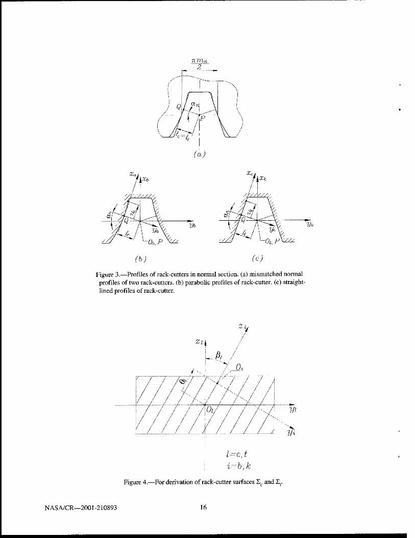
Case 2: The pinion tooth surface is shaved as a double-crowned one and the gear tooth surface is shaved as a conventional involute surface. In case 2 we apply two rack-cutters with mismatched profiles as shown in Fig. 3(a). The profiles are the normal sections of skew rack-cutters. One of the rack-cutters with straight- line profiles is applied for generation of gear screw involute shaver. The other rack-cutter is provided with parabolic profiles (Figs. 3(a) and 3(b)) and is applied for generation of profile crowned pinion. Application of rack-cutters shown in Fig. 3 improves the existing shaving process (see section 6).
Rack-Cutter Surfaces. We designate by Zc and I, surfaces of rack cutters applied for generation of pinion and gear shavers, respectively.
Coordinate systems Sa and Sb (Fig. 3(b)) are rigidly connected to the parabolic profile that is the normal section of Zc. The origin of coordinate system Sa coincides with point Q of tangency of mismatched rack- cutter profiles (Fig. 3(a)). Axes xa and ya are the tangent and the normal to the parabolic profile of the rack- cutter. Axis ya passes through point P.
NASA/CR—2001-210893
Surface Xr of the rack-cutter is generated wherein coordinate system Sb with the parabolic profile of the
rack-cutter performs translation along OcOb (Fig. 4). Axes zc and Zb form angle ßc that determines the
orientation of skew teeth of the rack-cutter. Parameters uc (Fig. 3(b)) and 6C =1 OcOb I (Fig. 4) are the surface
parameters of the skew rack-cutter. Fig. 4 shows the right-hand skew rack-cutter.
Surface Zc of the rack-cutter is determined by the following matrix equation (Figs. 3(b) and 4)
rc(uc,ec) = Mcb(6c)Mbara(uc) = Mca\ic -acu2
c 0 lj (2)
where a is the parabola coefficient of parabolic function {-a u ). Equation (2) means that surface Xc is c c
represented by vector function rc(uc,9c) which components are
where (Fig. 3(b))
xc = uc cosa„ + (acuc + lc)sina
yc = [uc sin an - (acuc + lc) cos an ] cos ßc + Bc sin ßc (3)
zc = [ucsinan-(acuc +lc)cosa„](-smßc) + 6ccosßc
= mnI1cosan_
4
Normal Nc to rack-cutter surface Lc is represented as
Similarly, we may represent surface 2, of rack-cutter of the gear shaver by vector function r/wf, 6t) taking
into account drawings of Fig. 3(c) and coordinate transformation from Se to St. Here,
rc(ut,9t) = Mtk(et)Mkere(ut)=Mte[ue 0 0 l]T (6)
Normal Nr to S, is represented as
N. = dut dOt
Nf =—-x—- (7)
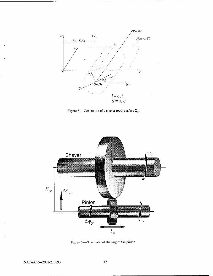
Derivation of Shaver Tooth Surface. The shaver tooth surface is generated by the rack-cutter that performs translational motion sd - rdyfd wherein the shaver performs rotational motion determined by
rotation angle y/d (Fig. 5). The axodes of the rack-cutter and the shaver are represented by plane II and
cylinder rd , respectively. Axis P-P is the instantaneous axis of rotation. Designation l=c, t and d=s, g
indicate rack-cutter surfaces Xc and Z, and the shaver surfaces Es and ~Lg designated for the pinion and the gear, respectively. Coordinate system Sm is the fixed one where the motions of the rack-cutters and the shavers are represented.
NASA/CR—2001-210893
Surface Zf/ of the shaver is represented by the equations
rrf(a„0,,^) = M1„(^)r,(M„0,) (8)
fdl(utA,¥d) = 0 (9)
Here: matrix equation (8) represents the family of rack-cutter Z/ (l=c, t) in coordinate system Sd. Equation (9) is the equation of meshing that may be determined considering the scalar equation
N^v'^^O (10)
or the rule that the normal to rack-cutter surface X, at the line of tangency of I; and ~Ld must pass through the instantaneous axis of rotation P-P [4].
3. Derivation of Pinion Tooth Surface Ex
Kinematics of Pinion Shaving. We consider two independent sets of parameters of motion that are performed during the shaving of the pinion (Fig. 6): Set 1: Combination of related rotations y/s and y/l of the shaver and the pinion, where y/s = (Nl IN1)\ffl.
Set 2: Combination of translation lp in direction of pinion axis, additional rotation of the pinion A\jfp and
plunge As i in the direction of shortest distance Esl. Here,
&vP=— (ID Pi
where /?, is the screw parameter of the pinion and
EsX=E0sX-Asp,=(rl + rs)-apll
2p (12)
Here E°{ and Esl are the initial and current magnitudes of the shortest distance; a , is the parabola
coefficient of the parabolic function (a ,l2); r, and rs are the radii of the pitch cylinders of the pinion and
the shaver, respectively.
In reality the second set of parameters of motion (it is the set of feed motions) becomes related with the first one after the speed of the feed is chosen. Consideration of the second set as an independent one with the respect to the first one permits determination of the shaved pinion tooth surface as independent to the feed motion.
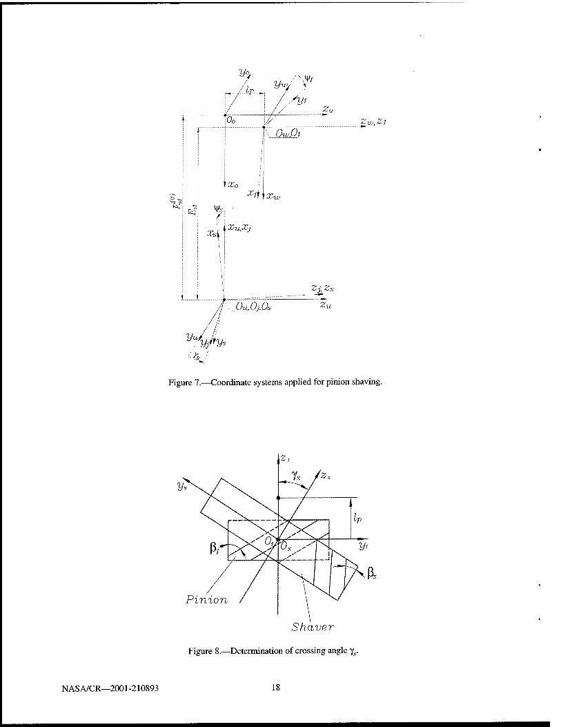
Applied Coordinate Systems. Coordinate systems Ss and 5, are rigidly connected to the shaver and the
pinion (Fig. 7). The meshing of the shaver and the pinion is considered in the basic fixed coordinate system S0. Rotation of S{ is considered in coordinate system SK. that performs translational motions / and spl
with respect to S0. Rotation of the shaver is considered in additional fixed coordinate system Su.
Axes zs and z, form a crossed angle ys determined as (Fig. 8)
y,=|ıA| <13>
NAS A/CR—2001-210893
where the upper (lower) sign correspond to application of the same (opposite) directions of the helices of the shaver and the pinion.
Pinion Tooth Surface. The derivation of the pinion tooth surface is based on application of two-parameter enveloping process [4,6] and requires the following procedure:
Step 1: Considering surface 2^ of the pinion shaver as given, we represent equations of the family of Zs in
coordinate system Sx rigidly connected to the pinion as follows
r1(us,es,ys,lp) = Mls(¥s,lp)rs(us,es) (14)
where y/s and / are the generalized independent parameters of motion; (us,ds) are the surface parameters
of the shaver.
The normal N*s) to the shaver surface ls is represented in S, by the following equation
where Lls is the (3x3) submatrix of (4x4) matrix Mls.
Step 2: In the case of two-parameter enveloping, we have to consider two (not one) equations of meshing that may be represented as follows
//I1)(«„eJ,^,/,) = N5"-v1
(,*-"', = o (16)
where v1<11,*'') is the relative velocity obtained for the condition that y/s is varied and lp is constant, and
/I<
I2,(«„0„^,/p) = Nj*)-v1
(1-'')=O (17)
Designation v1(b/',) means that the relative velocity is determined wherein parameter yrs is held at rest and
/ is varied.
Step 3: Instead of relative velocities, we may consider in equations (16) and (17) infinitesimal displacements in relative motion and represent the equations of meshing as follows
f«\us,es,Vs,lp) = N<" ■ |5- = 0 (Z, = const) (18)
/1i2)(«„0„V„/,) = Ni')-^- = O W,= const) (19)
The partial derivatives —- and —L can be expressed by the following matrix equations dy/s MP
dMij¥l)Mwo(lp)Mou(lp)MujM.(y,s) + dVs
NAS A/CR—2001-210893
Mln.(^1)M„,(/p)M0„(/;,)M, " r'-
and
dy/s
aM'';(y')M,ro(/<,)Mfl,,(//,)M„yMJJ(yJ) +
3M ,.„(/„) M,B.(y,) " ' M0„(/p)M„jM.(V/J +
Mh,.(^)M„,(/p)3M-(/p)M,,M. (^)
(20)
(21)
Matrix M,,,,^) depends not only on the parameter of motion i//, but also of the plunging motion
/ because (see equation (11)) variation of the axial position of the pinion must be accomplished by the
additional rotation A\j/p.
Step 4: Equations (14), (18), and (19), considered simultaneously, represent the shaved pinion tooth surface.
4. Derivation of Gear Tooth Surface Hi
We use for derivation an approach that is similar to the discussed one in section 3. Surface In is determined as the envelope to the two-parameter family of surfaces of gear shaver Ig. Two independent sets of motions are used for determination of the envelope In, but in the second set of motions the plunge is taken as zero. The derivations performed yield that gear tooth surface In is an involute one if the gear shaver surface Xg is a screw involute surface.
5. Tooth Contact Analysis (TCA)
The authors have developed a TCA computer program for simulation of meshing and contact of a shaved pinion and gear tooth surfaces I\ and In. The purposes of the simulation are:
1. That the point contact is localized and stabilized indeed. 2. Determination of the path of contact and bearing contact of shaved pinion-gear tooth surfaces
X] and X2. 3. The parabolic function of transmission errors of low magnitude is provided. 4. Investigation of influence of errors of alignment: (i) on the shift of the bearing contact, and
(ii) on the transmission errors.
The developed TCA computer program has been used for simulation of meshing and contact of helical and spur gears with parallel axes and helical gears with crossed axes.
In the cases of spur and helical gears with parallel axes, the pinion tooth surface is shaved as a double- crowned surface.
N AS A/CR—2001-210893
In the case of involute helical gears with crossed axes, the pinion-gear tooth surface are already in point contact and errors of alignment such as change of center distance, change of crossing angle and lead angle do not cause transmission error. Therefore, the pinion and gear shavers are provided with screw involute surfaces and double-crowning of the pinion is not required (see section 8).
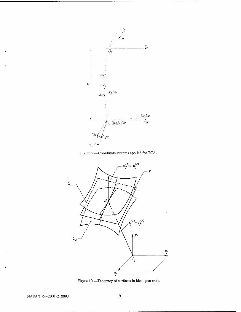
Algorithm of TCA for Simulation of Meshing. For the purpose of simplification of discussions, we consider that surfaces X, and X2 and their normals N, and N2 are represented in two-parameter form
in coordinate systems S] and S2.
We apply movable coordinate systems S, and S2 rigidly connected to the pinion and gear,
respectively, and fixed coordinate system Sf (Fig. 9). An auxiliary coordinate system Sr (Fig. 9) is
used for simplification of coordinate transformation. Three types of errors are considered: change of center distance AE , shaft angle Ay, and error AA of the lead angle of the gear.
The algorithm of TCA is based on simulation of continuous tangency of pinion-gear tooth surfaces. Using coordinate transformation, we represent surfaces 11 and S2 in fixed coordinate system Sf (Fig.
9). Continuous tangency of shaved surfaces 1{ and X2 is provided by observation of the following
vector equations (Fig. 10)
r(p(uv9i,<t>i)-rf\u2,G2,<p1) = H (22)
nJ!)(M1,01,^)-nf(M2,02,^) = O (23)
where n<J!'(/ = l,2) is the surface unit normal.
Vector equation (23) yields only two independent equations since n^ = n^2) = 1. Instead of equality
of surface unit normals, we may require colUnearity of surface normals using the equation
N^=ANf a *0) (24)
Equation (22) and (23) provide a system of five nonlinear equations in six unknowns represented as
fi(ul,dl,<l>1,u2,62,<l)2) = 0 (/ = 1,...,5) (25)
The Theorem of Implicit Functions System Existence yields that we may consider one of the parameters, say 0,, as the input one and obtain the solution to equation system (25) by functions
{Ml(01),Ö1(01),M2(0I),Ö2(01),02(01)}e C(1> (26)
if the following conditions are observed
f.eC\ IMlAlJkJ^M^o (27) o(Wj,0,,W2,02,02)
Then, we may obtain [4,5]:
(i) the paths of contact on surfaces £[ and £2 determined as
iK«,.^),^)), (i = l,2) (28)
NASA/CR—2001-210893

and
(ii) the function of transmission errors
A<M^) = ^>)-7rtf>. (29) N-,
Parabolic Function of Transmission Errors. The approach developed enables a predesigned parabolic function of transmission errors to be obtained:
A0, = -atf (30)
for shaving spur and helical gears.
In the case of shaving of spur gears, function (30) is provided by application of a profile crowned pinion shaver. Longitudinal crowning of the pinion is necessary for localization of the bearing contact and is accomplished by the plunging of the shaver during the process of shaving of the pinion (see section 3).
In case of shaving of helical gears, parabolic function (30) is provided due to plunging of the shaver during the shaving of the pinion. Profile crowning of the pinion shaver provides localization of the bearing contact.
It has been proven that a parabolic function of transmission errors is able to absorb a discontinuous linear function of transmission errors caused by misalignment [4, 5]. Discontinuous functions of transmission errors cause vibration and noise. Therefore, absorption of discontinuous linear functions of transmission errors by application of developed parabolic function of transmission errors is a great advantage of the developed approach for shaving.
Simulation of Bearing Contact. The shaver and workpiece tooth surfaces, as well the pinion-gear tooth surfaces, are in point contact at every instant. The contact is spread over an elliptical area due to the elastic deformation of tooth surfaces. The bearing contact during the process of shaving and during the meshing of shaved tooth surfaces is formed by a set of instantaneous contact ellipses. The determination of dimensions and orientation of the contact ellipse require knowledge of principal curvatures and principal directions of contacting surfaces and the approach of contacting surfaces as the result of elastic deformation. We refer to [4, 5] for the solution of this problem.
The shaved gear tooth surface is a screw involute surface and determination of principal curvatures and directions for such a surface is a simple problem [4, 5]. However, it is a more complex problem for a double-crowned pinion tooth surface. Taking into account that the deviations of a double-crowned pinion from an involute surface are in the range of ( 0.01-0.05)mm, we may determine the pinion principal curvatures and directions as for an involute surface.
The contact of the shaver and the workpiece is also spread over an elliptical area. For the purpose of simplification, we will consider the contact of the shaver and the workpiece as the contact of crossed involute gears.
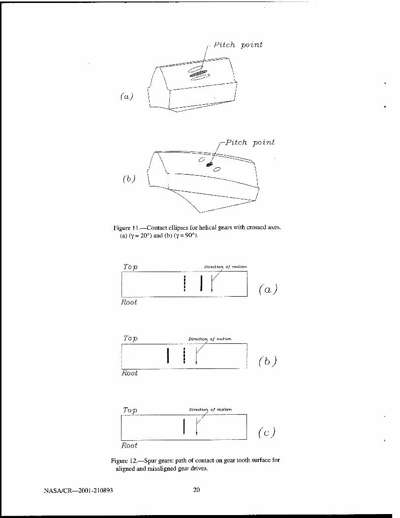
Numerical Example 1: Contact Ellipse for Crossed Helical Gears. We will consider two cases of
crossed helical gears: (i) with the crossing angle A = 20°, and (ii) with the crossing angle X = 90°. The first case corresponds to the contact of a shaver with the workpiece. The second case corresponds to a
NAS A/CR—2001-210893
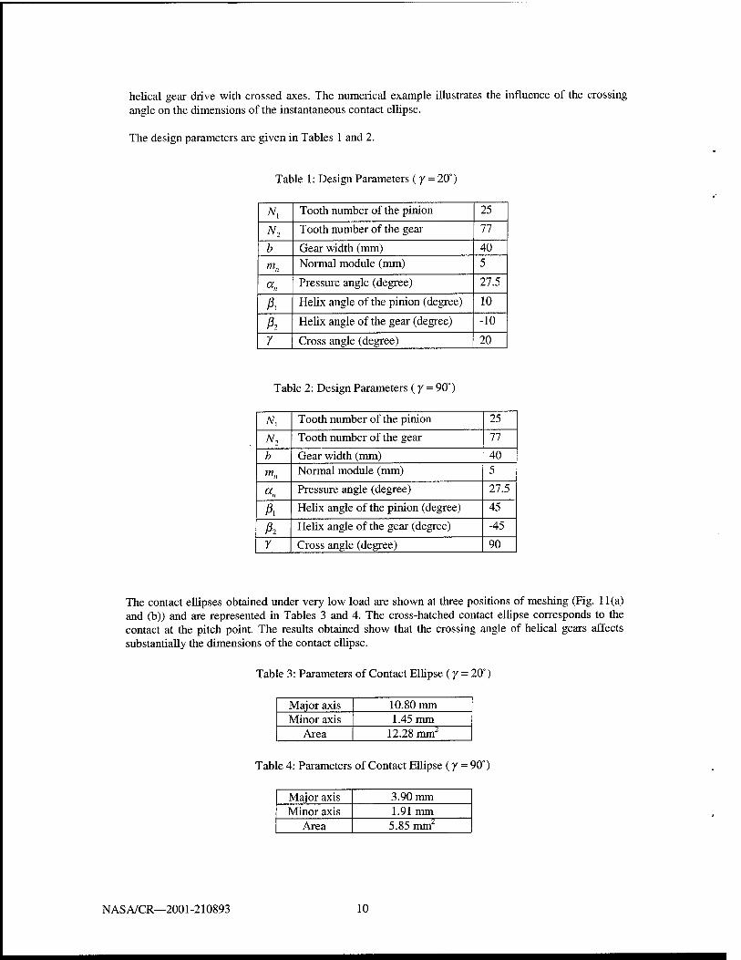
helical gear drive with crossed axes. The numerical example illustrates the influence of the crossing angle on the dimensions of the instantaneous contact ellipse.
The design parameters are given in Tables 1 and 2.
Table 1: Design Parameters (y = 20°)
Ny Tooth number of the pinion 25
N2 Tooth number of the gear 77
b Gear width (mm) 40
mn Normal module (mm) 5
"„ Pressure angle (degree) 27.5
A Helix angle of the pinion (degree) 10
ß2 Helix angle of the gear (degree) -10
7 Cross angle (degree) 20
Table 2: Design Parameters (y = 90°)
Ni Tooth number of the pinion 25
N2 Tooth number of the gear 77
b Gear width (mm) 40 mn Normal module (mm) 5
<*« Pressure angle (degree) 27.5
A Helix angle of the pinion (degree) 45
A Helix angle of the gear (degree) -45
7 Cross angle (degree) 90
The contact ellipses obtained under very low load are shown at three positions of meshing (Fig. 11(a) and (b)) and are represented in Tables 3 and 4. The cross-hatched contact ellipse corresponds to the contact at the pitch point. The results obtained show that the crossing angle of helical gears affects substantially the dimensions of the contact ellipse.
Table 3: Parameters of Contact Ellipse (y = 20°)
Major axis 10.80 mm Minor axis 1.45 mm
Area 12.28 mm2
Table 4: Parameters of Contact Ellipse (y = 90°)
Major axis 3.90 mm Minor axis 1.91mm
Area 5.85 mm2
NASA/CR—2001-210893 10
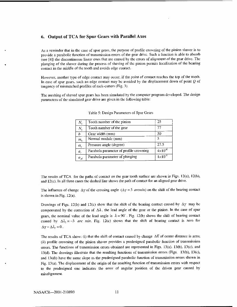
6. Output of TCA for Spur Gears with Parallel Axes
As a reminder that in the case of spur gears, the purpose of profile crowning of the pinion shaver is to provide a parabolic function of transmission errors of the gear drive. Such a function is able to absorb (see [4]) the discontinuous linear ones that are caused by the errors of alignment of the gear drive. The plunging of the shaver during the process of shaving of the pinion permits localization of the bearing contact in the middle of the tooth and avoids edge contact.
However, another type of edge contact may occur, if the point of contact reaches the top of the tooth. In case of spur gears, such an edge contact may be avoided by the displacement down of point Q of tangency of mismatched profiles of rack-cutters (Fig. 3).
The meshing of shaved spur gears has been simulated by the computer program developed. The design parameters of the simulated gear drive are given in the following table:
Table 5: Design Parameters of Spur Gears
Nx Tooth number of the pinion 25
Nx Tooth number of the gear 77
b Gear width (mm) 50 m« Normal module (mm) 5
«» Pressure angle (degree) 27.5
"c Parabola parameter of profile crowning 4X10⁻⁴
apl
Parabola parameter of plunging lxlO-4
The results of TCA for the paths of contact on the gear tooth surface are shown in Figs. 12(a), 12(b), and 12(c). In all three cases the dashed line shows the path of contact for an aligned gear drive.
The influence of change Ay of the crossing angle (Ay = 3 arcmin) on the shift of the bearing contact
is shown in Fig. 12(a).
Drawings of Figs. 12(b) and 12(c) show that the shift of the bearing contact caused by Ay may be
compensated by the correction of AA, the lead angle of the gear or the pinion. In the case of spur
gears, the nominal value of the lead angle is X = 90°. Fig. 12(b) shows the shift of bearing contact caused by AAo=-3 arc min. Fig. 12(c) shows that the shift of bearing contact is zero for
Ay + AX,=0.
The results of TCA show: (i) that the shift of contact caused by change AE of center distance is zero; (ii) profile crowning of the pinion shaver provides a predesigned parabolic function of transmission errors. The functions of transmission errors obtained are represented in Figs. 13(a), 13(b), 13(c), and 13(d). The drawings illustrate that the resulting functions of transmission errors (Figs. 13(b), 13(c), and 13(d)) have the same slope as the predesigned parabolic function of transmission errors shown in Fig. 13(a). The displacement of the origin of the resulting function of transmission errors with respect to the predesigned one indicates the error of angular position of the driven gear caused by
misalignment.
N AS A/CR—2001-210893 11
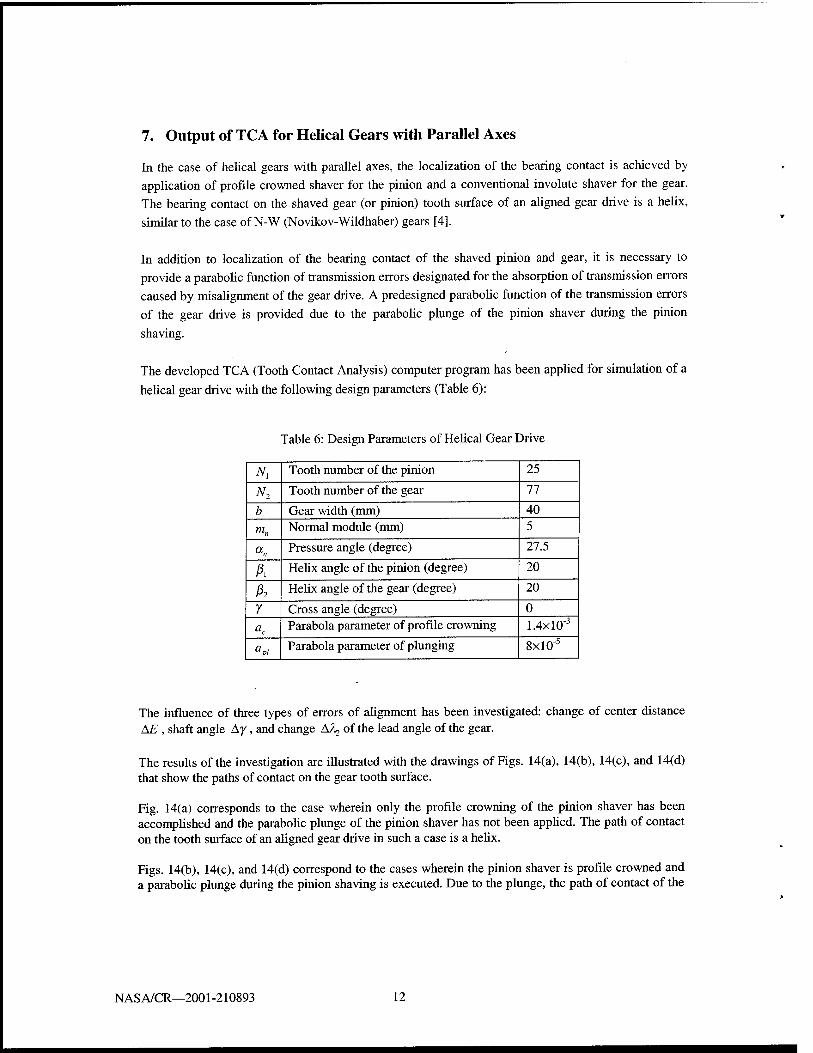
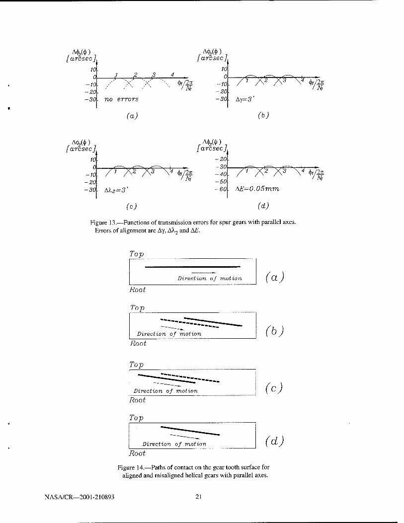
7. Output of TCA for Helical Gears with Parallel Axes
In the case of helical gears with parallel axes, the localization of the bearing contact is achieved by application of profile crowned shaver for the pinion and a conventional involute shaver for the gear. The bearing contact on the shaved gear (or pinion) tooth surface of an aligned gear drive is a helix,
similar to the case of N-W (Novikov-Wildhaber) gears [4].
In addition to localization of the bearing contact of the shaved pinion and gear, it is necessary to provide a parabolic function of transmission errors designated for the absorption of transmission errors caused by misalignment of the gear drive. A predesigned parabolic function of the transmission errors
of the gear drive is provided due to the parabolic plunge of the pinion shaver during the pinion
shaving.
The developed TCA (Tooth Contact Analysis) computer program has been applied for simulation of a
helical gear drive with the following design parameters (Table 6):
Table 6: Design Parameters of Helical Gear Drive
tfl Tooth number of the pinion 25
^2 Tooth number of the gear 77
b Gear width (mm) 40
m„ Normal module (mm) 5
<*n Pressure angle (degree) 27.5
Ä Helix angle of the pinion (degree) 20
A Helix angle of the gear (degree) 20
Y Cross angle (degree) 0 ac
Parabola parameter of profile crowning 1.4xl0"3
apl
Parabola parameter of plunging 8xl0"5
The influence of three types of errors of alignment has been investigated: change of center distance \F., shaft angle Ay, and change A/U of the lead angle of the gear.
The results of the investigation are illustrated with the drawings of Figs. 14(a), 14(b), 14(c), and 14(d) that show the paths of contact on the gear tooth surface.
Fig. 14(a) corresponds to the case wherein only the profile crowning of the pinion shaver has been accomplished and the parabolic plunge of the pinion shaver has not been applied. The path of contact on the tooth surface of an aligned gear drive in such a case is a helix.
Figs. 14(b), 14(c), and 14(d) correspond to the cases wherein the pinion shaver is profile crowned and a parabolic plunge during the pinion shaving is executed. Due to the plunge, the path of contact of the
NASA/CR—2001-210893 12

gear drive deviates from a helix, even for an aligned gear drive. The magnitude of the deviation depends on the assigned magnitude of the predesign parabolic function of transmission errors.
The path of contact indicated in Fig. 14(b) by continuous line corresponds to Ay = 3 arcmin. The
dashed line in Fig. 14(b) illustrates the path of contact for Ay = 0.
Similarly, 14(c) indicates paths of contact obtained for AA, = -3 arcmin and AA, = 0.
A combination of errors of alignment Ay + AX, = 0 enables to avoid the shift of the bearing contact.
Fig. 14(d) shows that error of alignment AE = 0.05 mm does not cause the shift of the bearing contact.
The paths of contact shown in Figs. 14(b), 14(c), and 14(d) deviate from a helix shape of path of contact as the result of a parabolic plunge of the pinion shaver. However, such a plunge is required because it provides a parabolic function of transmission errors and therefore the noise and vibration of the drive should be reduced. The existence of a parabolic function of transmission errors is confirmed
by application of the developed TCA computer program.
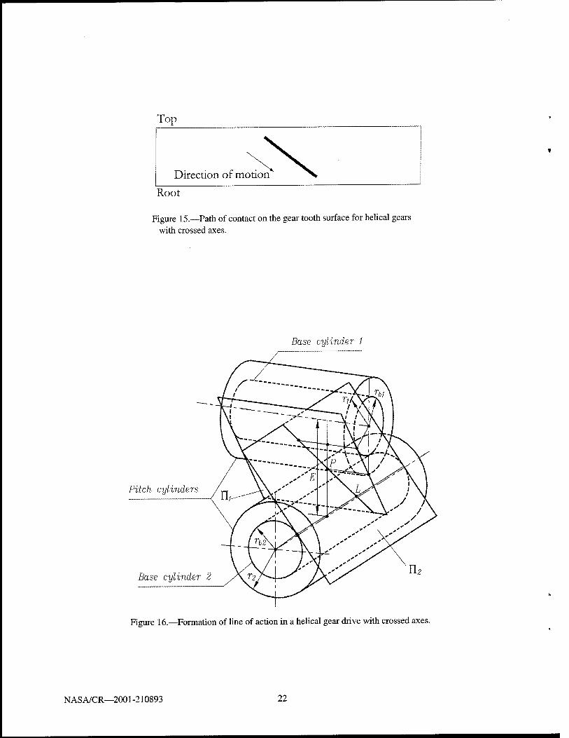
8. Output of TCA for Helical Gears with Crossed Axes
We consider a gear drive formed by helical gears with screw involute tooth surfaces and crossed axes. The crossing angle y is determined as
y=|A±&| <31> where j3, is the helix angle. The upper and lower sign in (31) corresponds to the same and opposite
directions of teeth, respectively.
The investigation of meshing of helical gears with crossed axes accomplished in [4,6] shows:
(i) The gear tooth surfaces are in point contact and therefore their bearing contact is localized. The path of contact on gear tooth surface is shown in Fig. 15.
(ii) The advantage of crossed involute helical gears is that the change Ay of the crossing angle, change
AE of the shortest distance between the axes, and change Aß of the helix angle do not cause transmission errors. This statement has been proven in [6] and confirmed by application of TCA computer program developed by the authors of this paper.
(iii) However, due to small dimensions of the instantaneous contact ellipse (see Fig. 11) helical gears with crossed axes may be applied to gear drives that operate with light loads.
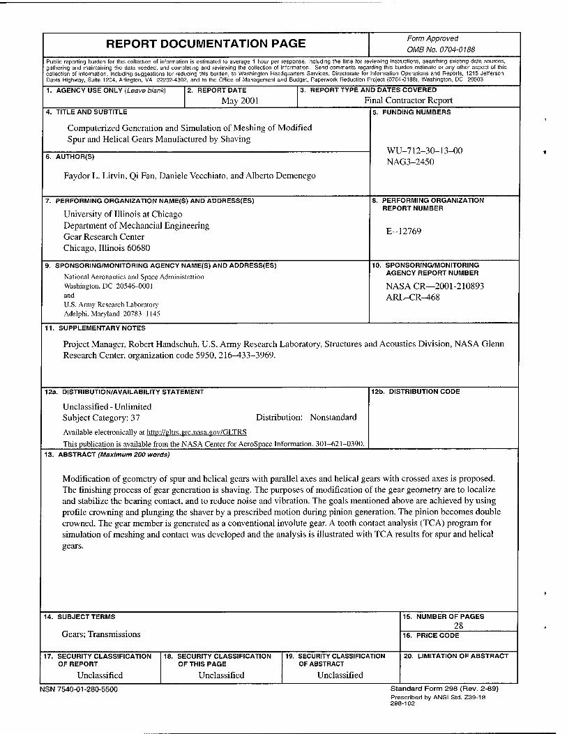
The specific conditions of meshing of crossed involute helical gears are illustrated with drawings of Fig. 16. The line of action of the gears is the line of intersection of two planes that are tangent to the respective base cylinders of the helical gears.
There are two lines of action that correspond to meshing of both sides of tooth surfaces. Both lines of action in an aligned gear drive intersect each other at a common point P that lies on the shortest center distance. In case of a misaligned gear drive, the lines of action are still tangents to the base cylinder but do not intersect each other at pitch point P.
Unlike spur and helical gear drives with parallel axes, there is no need for double-crowning of helical gears with crossed axes. As it was mentioned above, such gear tooth surfaces are in point contact, the
NASA/CR—2001-210893 13
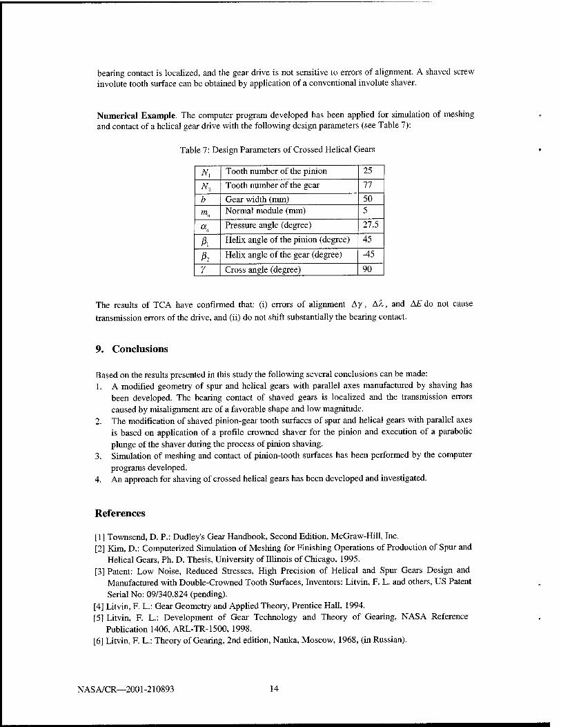
bearing contact is localized, and the gear drive is not sensitive to errors of alignment. A shaved screw involute tooth surface can be obtained by application of a conventional involute shaver.
Numerical Example. The computer program developed has been applied for simulation of meshing and contact of a helical gear drive with the following design parameters (see Table 7):
Table 7: Design Parameters of Crossed Helical Gears
Ni Tooth number of the pinion 25
N2 Tooth number of the gear 77
b Gear width (mm) 50
m„ Normal module (mm) 5
«„ Pressure angle (degree) 27.5
A Helix angle of the pinion (degree) 45
h Helix angle of the gear (degree) -45
r Cross angle (degree) 90
The results of TCA have confirmed that: (i) errors of alignment Ay, AA, and AE do not cause
transmission errors of the drive, and (ii) do not shift substantially the bearing contact.
9. Conclusions
Based on the results presented in this study the following several conclusions can be made: 1. A modified geometry of spur and helical gears with parallel axes manufactured by shaving has
been developed. The bearing contact of shaved gears is localized and the transmission errors caused by misalignment are of a favorable shape and low magnitude. The modification of shaved pinion-gear tooth surfaces of spur and helical gears with parallel axes is based on application of a profile crowned shaver for the pinion and execution of a parabolic plunge of the shaver during the process of pinion shaving. Simulation of meshing and contact of pinion-tooth surfaces has been performed by the computer programs developed.
4. An approach for shaving of crossed helical gears has been developed and investigated.
2.
3.
References
[1] Townsend, D. P.: Dudley's Gear Handbook, Second Edition, McGraw-Hill, Inc. [2] Kim, D.: Computerized Simulation of Meshing for Finishing Operations of Production of Spur and
Helical Gears, Ph. D. Thesis, University of Illinois of Chicago, 1995. [3] Patent: Low Noise, Reduced Stresses, High Precision of Helical and Spur Gears Design and
Manufactured with Double-Crowned Tooth Surfaces, Inventors: Litvin, F. L. and others, US Patent Serial No: 09/340.824 (pending).
[4] Litvin, F. L.: Gear Geometry and Applied Theory, Prentice Hall, 1994. [5] Litvin, F. L.: Development of Gear Technology and Theory of Gearing, NASA Reference
Publication 1406, ARL-TR-1500,1998. [6] Litvin, F. L.: Theory of Gearing, 2nd edition, Nauka, Moscow, 1968, (in Russian).
NAS A/CR—2001 -210893 14

Figure 1.—Illustration of a shaver as a helical gear with gashed teeth.
Shaver tooth
Top
Direction of motion.
(a) Bottom
Workpiece tooth Top
Direction of motion (b) Bottom
Figure 2.—Contact paths on shaver and workpiece tooth surfaces.
NASA/CR—2001 -210893 15
nrrin 9""
Q a.
IP w w
faj
■a.p
(b) (o)
Figure 3.—Profiles of rack-cutters in normal section, (a) mismatched normal profiles of two rack-cutters, (b) parabolic profiles of rack-cutter, (c) straight- lined profiles of rack-cutter.
zn
/--
A /
7 7 7 7w7 7ST7 7 7 1 / / ,
/ /
/ / -/■
*../:/;sc// -y—/.>.^.../....
' / / /7Y7777 / / / / /... / / ._/ z..
^
&
Figure 4.—For derivation of rack-cutter surfaces Xc and Sf
NASA/CR—2001-210893 16
l=c,t d=s,g
Figure 5.—Generation of a shaver tooth surface Xrf.
Figure 6.—Schematic of shaving of the pinion.
N AS A/CR—2001 -210893 17
A -1 / /
to
-60
Oo \//
IXo Xfi
OwPl
\Xxu
Xsi 1 Xu,Xj
.! L /fTalcÖT
//
^;i Wr^5
ij, ^s
2«
Ztu,^'/
Figure 7.—Coordinate systems applied for pinion shaving.
Pinion
Shaver
Figure 8.—Determination of crossing angle ys.
NASA/CR—2001-210893 18
r0-,
XU :
Zl
X2i \Xf.Xr
HJyz
/[ZMQr.02 Zf
Y....''
Figure 9.—Coordinate systems applied for TCA.
JO-JV lit — nf
Figure 10.—Tangency of surfaces in ideal gear train.
N AS A/CR—2001-210893 19
(a)
Pitch point
(b)
Pitch point
Figure 11.—Contact ellipses for helical gears with crossed axes. (a)(Y=20°)and(b)(Y=90°).
Top
Root
Direction of motion
1 1 1/ a)
Top
Root
Direction of motion
i it' (b)
7*0 T) Direction of motion
1 Root
(c)
Figure 12.—Spur gears: path of contact on gear tooth surface for aligned and misaligned gear drives.
NAS A/CR—2001 -210893 20
/ arcsecj 10- 0. 4-
-10- / -20- -30- no errors
(a)
/ arcsecj
<W2jt
10 0
-10 -20 -30 Ay=3'
(b)
>*/%
rA^)7 / arcsecj
10. 0.
-10. -20-
/ arcsecj
■yfyfyf '*#
-30- Al2=3'
-20 -30 -40 -50- -60
/'/ ^2 ^3 V k/M N,
(c)
. AE=0.05mm
(d)
Figure 13.—Functions of transmission errors for spur gears with parallel axes. Errors of alignment are Ay, A\2 and AE.
Top
motion Direction of
Root
Top
Direction of motion
(a)
(b) Root
(c) Root
(d) Root
Figure 14.—Paths of contact on the gear tooth surface for aligned and misaligned helical gears with parallel axes.
NASA/CR—2001 -210893 21
Top
Direction of motion
Root
Figure 15.—Path of contact on the gear tooth surface for helical gears with crossed axes.
Base cylinder
Pitch cylinders
Base cylinder 2
Figure 16.—Formation of line of action in a helical gear drive with crossed axes.
NASA/CR—2001-210893 22
REPORT DOCUMENTATION PAGE Form Approved OMB No. 0704-0188
Public reporting burden for this collection of information is estimated to average 1 hour per response, including the time for reviewing instructions, searching existing data sources, gathering and maintaining the data needed, and completing and reviewing the collection of information. Send comments regarding this burden estimate or any other aspect of this collection of information, including suggestions for reducing this burden, to Washington Headquarters Services, Directorate for Information Operations and Reports, 1215 Jefferson Davis Highway, Suite 1204, Arlington, VA 22202-4302, and to the Office of Management and Budget, Paperwork Reduction Project (0704-0188), Washington, DC 20503.
1. AGENCY USE ONLY (Leave blank) 2. REPORT DATE
May 2001 3. REPORT TYPE AND DATES COVERED
Final Contractor Report 4. TITLE AND SUBTITLE
Computerized Generation and Simulation of Meshing of Modified Spur and Helical Gears Manufactured by Shaving
5. FUNDING NUMBERS
WU 712 30 13 00 NAG3-2450
6. AUTHOR(S)
Faydor L. Litvin, Qi Fan, Daniele Vecchiato, and Alberto Demenego
7. PERFORMING ORGANIZATION NAME(S) AND ADDRESS(ES)
University of Illinois at Chicago Department of Mechancial Engineering Gear Research Center Chicago, Illinois 60680
8. PERFORMING ORGANIZATION REPORT NUMBER
E-12769
9. SPONSORING/MONITORING AGENCY NAME(S) AND ADDRESS(ES)
National Aeronautics and Space Administration Washington, DC 20546-0001 and U.S. Army Research Laboratory Adelphi, Maryland 20783-1145
10. SPONSORING/MONITORING AGENCY REPORT NUMBER
NASA CR—2001-210893 ARL-CR-468
11. SUPPLEMENTARY NOTES
Project Manager, Robert Handschuh, U.S. Army Research Laboratory, Structures and Acoustics Division, NASA Glenn Research Center, organization code 5950, 216-433-3969.
12a. DISTRIBUTION/AVAILABILITY STATEMENT
Unclassified - Unlimited Subject Category: 37 Distribution: Nonstandard
Available electronically at http://gltrs.grc.nasa.sov/GLTRS
This publication is available from the NASA Center for AeroSpace Information. 301-621-0390.
12b. DISTRIBUTION CODE
13. ABSTRACT (Maximum 200 words)
Modification of geometry of spur and helical gears with parallel axes and helical gears with crossed axes is proposed. The finishing process of gear generation is shaving. The purposes of modification of the gear geometry are to localize and stabilize the bearing contact, and to reduce noise and vibration. The goals mentioned above are achieved by using profile crowning and plunging the shaver by a prescribed motion during pinion generation. The pinion becomes double crowned. The gear member is generated as a conventional involute gear. A tooth contact analysis (TCA) program for simulation of meshing and contact was developed and the analysis is illustrated with TCA results for spur and helical gears.
14. SUBJECT TERMS
Gears; Transmissions
15. NUMBER OF PAGES 28
16. PRICE CODE
17. SECURITY CLASSIFICATION OF REPORT
Unclassified
18. SECURITY CLASSIFICATION OF THIS PAGE
Unclassified
19. SECURITY CLASSIFICATION OF ABSTRACT
Unclassified
20. LIMITATION OF ABSTRACT
NSN 7540-01-280-5500 Standard Form 298 (Rev. 2-89) Prescribed by ANSI Std. Z39-18 298-102