a minimum-energy mission plan for the manned exploration of mars
TRANSCRIPT

I N A S A TECHNICAL NOTE N A S A TN D-5502
A MINIMUM-ENERGY MISSION PLAN FOR THE MANNED EXPLORATION OF MARS
by James J . Taylor and Sam W. Wilson, Jr.
Manned Spacecrafi Center Honston, Texas
NATIONAL AERONAUTICS AND SPACE ADMINISTRATION WASHINGTON, D. C. NOVEMBER 1969
https://ntrs.nasa.gov/search.jsp?R=19700002308 2018-02-21T18:05:51+00:00Z

A MINIMUM-ENERGY MISSION PLAN FOR THE MANNED EXPLORATION OF MARS
Manned Spacecraft Center Houston, Texas 79058
National Aeronautics and Space Administration Technical Note Washington, D. C. 20546
booster, each capable of placing a 400 000-pound payload into a 260-nautical-mile orbit, a r e used to assemble the spacecraft and the trans-Mars-injection stages. The launch window for the minimum-energy mission is relatively insensitive to delayed launches o r interrupted departure sequences. From technological considerations, the minimum-energy mission is feasible and permits the accomplishment of an increased l ist of scientific objectives.
Launch Window Unc las s i f i ed - Unlinl i ted ' Orbital Departure ' Minimum Energy Missio ' Assembly Orbits
19. S E C U R I T Y C L A S S I F I C A T I O N 20. S E C U R I T Y C L A S S I F I C A T I O N
@ H I S REPORT) (THIS PAGE)
Unclassified Unclassified
* F o r sa l e by the Clearinghouse for Federa l Sciei~tif ic and Technical Inforination
Springfield, Virginia 22 15 1

CONTENTS
Section Page
SUMMARY . . . . . . . . . . . . . . . . . . . . . . . . . . . . . . . . . . . . . 1
INTRODUCTION . . . . . . . . . . . . . . . . . . . . . . . . . . . . . . . . . . 2
SYMBOLS . . . . . . . . . . . . . . . . . . . . . . . . . . . . . . . . . . . . . . 3
NOMINAL MISSION PROFILE . . . . . . . . . . . . . . . . . . . . . . . . . . . 5
Heliocentric Phase . . . . . . . . . . . . . . . . . . . . . . . . . . . . . . . 5
. . . . . . . . . . . . . . . . . . . . . . . . . . . . . Trans-Mars Injection 6
. . . . . . . . . . . . . . . . . . . . . . . . . . . . . . . Mars-Orbit Design 7
Mars-Orbital Insertion . . . . . . . . . . . . . . . . . . . . . . . . . . . . . 8
. . . . . . . . . . . . . . . . . . . . . . . . . . . . . Trans-Earth Injection 9
. . . . . . . . . . . . . . . . . . . . . . . . . . FLIGHT-PLAN EVALUATION 12
. . . . . . . . . . . . . . . . . . . . . . . . . . . . . Mission Opportunities 12
Spacecraft Perforniance Requirements . . . . . . . . . . . . . . . . . . . . 14
Orbital-Launch Vehicle . . . . . . . . . . . . . . . . . . . . . . . . . . . . 16
. . . . . . . . . . . . . . . . . . . . . . . . . . LAUNCH-WINDOW ANALYSIS 27
Orbital-Departure Window Definitions . . . . . . . . . . . . . . . . . . . . . 27
Multiple-Impulse Orbital-Departure Technique . . . . . . . . . . . . . . . . 28
. . . . . . . . . . . . . . . . . . . . . . . . . . . . . . . . . Gravity Losses 29
. . . . . . . . . . . . . . . . . . . . . . . . . . Assembly-Orbit Parameters 29
. . . . . . . . . . . . . . . . . . . . . . . . . . . Circular Assembly Orbits 30
. . . . . . . . . . . . . . . . . . . . . . . . . . Elliptical Assembly Orbits 31
. . . . . . . . . . . . . . . . . . . . . . . . . . . . . . LAUNCH SCHEDULES 45
. . . . . . . . . . . . . . . . . . . . . . . . . . . . . . . . . . . CONCLUSIONS 65
iii

Section Page
APPENDIX - EARTH DEPARTURE HYPERBOLIC-EXCESS- VELOCITY VECTORS . . . . . . . . . . . . . . . . . . . . . 66
REFERENCES . . . . . . . . . . . . . . . . . . . . . . . . . . . . . . . . . . . 72

TABLES
P a g e Tab le
9
11
VII
VEI
L;rg
X
N0I.T-MISSON-BEPETdDENT VELOCITY BUDGET' . . . . . . . . . . . . 17
OPPORTUNITIES FOR A MIMMUM-ENERGY MARS-LANDING . . . . . . . . . . . . . . . . . . . . . . . . . . . . . . . . MISSION 1 8
. . . . . . . . . . . . . . . . . SPACECRCbFT WEIGHT ASSUMPTIONS 19
PROPULSION-SYSTEM PERFORMANCE ASSUMPTIONS . . . . . . . . 19
VARIATION IN TOTAL SPACECRAFT WEIGHT FOR AEROBRAKED LANDER . . . . . . . . . . . . . . . . . . . . . . . . . . . . . . . . 20
VARIATION IN TOTAL SPACECRAFT WEIGHT FOR NON- . . . . . . . . . . . . . . . . . . . . . . . . AEROBRAMED LANDER 20
ORBITAL -LAUNCH -VEHICLE WEIGHT SUMMARY . . . . . . . . . . . 2 1
. . . . . ORBITAL-LAmCH-VEHICLE PERFORMANCE CAPABILITY 21
. . . . . . . . . . . . . CIRCULAR ASSEMBLY -ORBIT P A M M E T E R S 33
LAUNCH -SCHEDULE SUMMARY FOR MARS C O N J W C T m N - . . . . . . . . . . . . . . . . . . . . . . . . . . . . CLASS MISSIONS 46
ORBITAL-DEPARTURE WINDOWS FOR DELAYED SPACECRAFT . . . . . . . . . . . . . . . . . . . . . . . . . . . . . L A U N C H E S . . 49
EARTH-DEPARTURE Tm VECTORS AND To MAGNITUDE FOR
THE 19'79 MARS CONJUNCTION-CLASS -MISSION LAUNCH . . . . . . . . . . . . . . . . . . . . . . . . . . . . . . . . WINDOW 6'9
XEI EARTH-DEPARTURE TW VECTORS AND To MAGNITUDE FOR
THE 19'79 MARS CONJUNC TION-CLASS-MISSION LAUNCH . . . . . . . . . . . . . . . . . . . . . . . . . . . . . . . . WINDOW 68
XW EARTH-DEPARTURE 5, VECTORS AND To MAGNITUDE FOR
THE 1981 MARS CONJUNCTION-CLASS-MISSION LAUNCH . . . . . . . . . . . . . . . . . . . . . . . . . . . . . . . . WINDOW 69
XV EARTH-DEPARTURE tm VECTORS AND TO MAGNITUDE FOR
THE 1983 MARS CONJUNCTION-CLASS-MISSION LAUNCH . . . . . . . . . . . . . . . . . . . . . . . . . . . . . . . . WINDOW '70

FIGURES
Figure Page
1 Heliocentric phase of the nominal minimum-energy Mass-landing . . . . . . . . . . . . . . . . . . . . . . . . . . . . mission profile 10
. . . . . . . . . . . . . . . . . . . . 2 Earth-orbital operations for TMI 10
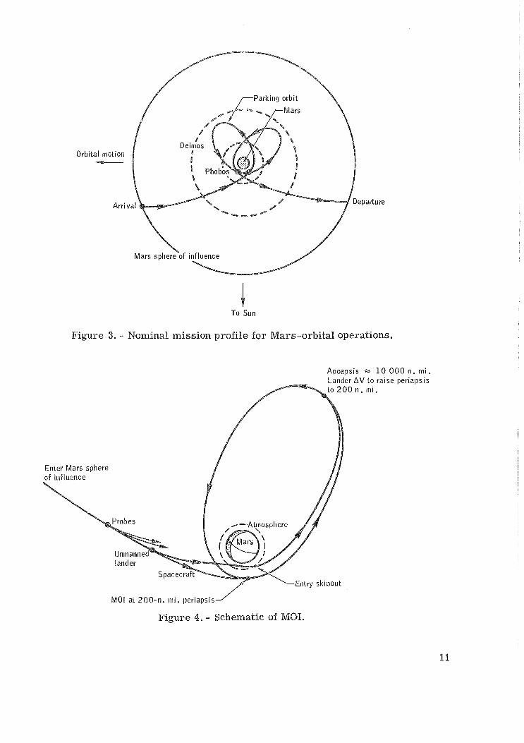
. . . . . . . . . 3 Nominal mission profile f o r Mars-orbital operations 11
. . . . . . . . . . . . . . . . . . . . . . . . . . . . 4 Schematic of MOI 11
5 Velocity requirements for t ransfer f rom Earth to Mass in 1983 . . . . . . . . . . . . . . . . . . . with a total t r ip t ime of 280 days 22
6 Velocity requirements for transfer f rom Mars to Earth in 1983 . . . . . . . . . . . . . . . . . . . with a total t r ip time of 300 days 23
. . . . . . . . . 7 Conjunction-class Mars-landing mission opportunities 24
. . . . . . . . . . . . . . . . . . . . . . 8 Mars ephemeris parameters 25
. . . . . . . . . . . . . . . . . . 9 Orbit-assembly launch configurations 25
10 Ideal AV a s a function of OLV-stage mass and auxiliary . . . . . . . . . . . . . . . . . . . . . . . . . . . . . . . . payload 26
. . . . . . . . . . . . . 11 Launch-schedule constraints and interactions 34
. . . . . . . . . . . . . . . . 12 Definition of orbital-departure windows 35
13 Assembly-orbit and departure-asymptote coordinates relative to equinox and equator . . . . . . . . . . . . . . . . . . . . . . . . . . 35
14 Assembly-orbit and departure-asymptote coordinates relative to . . . . . . . . . . . . . . . . . . assembly -orbit node and equator 36
. . . . . . . . . . . 15 Geometry of the five-impulse departure technique 36
16 Comparison of nodal windows for one.impulse. two.impulse. . . . . . . . . . . . . . . . . . . . . and three-impulse departures 39
17 Effect of final ellipse s ize on nodal window (nominal . . . . . . . . . . . . . orbi t orientation). 197 7 mission opportunity 38
18 Comparison of chord-type and a r c - type plane-change . . . . . . . . . . . . . . . . . . . . . . . . . . velocity increments 39

Figure Page
Circular assembly- orbit altitudes to provide direct-rendezvous . . . . . . . . . . . . . . . . . . . . . . . . . . . . . . . . capability 39
Effect of 8 on nodal window for c ircular assembly orbit (gravity 8
losses included), 1981 mission opportunity . . . . . . . . . . . . . . 40
Effect of inclination on nodal window for c ircular assembly orbit (gravity losses included), 1981 mission opportunity . . . . . . . . . 41
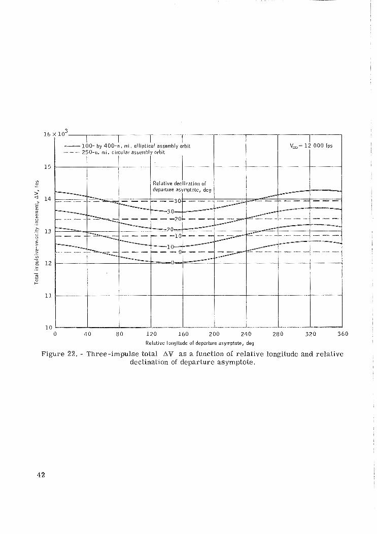
Three-impulse total AV as a function of relative longitude and relative declination of departure asymptote . . . . . . . . . . . . . 42
Effect of apsidal orientation on nodal window (nominal nodal . . . . . . . . . . . . . . . . orientation), 1977 mission opportunity 43
Comparison of orbital-departure windows for elliptical and circular . . . . . . . . . . . . . . assembly orbits, 1981 mission opportunity 44
Launch schedule for the 1977 mission opportunity using circular . . . . . . . . . . . . . . . . . . . . . . . . . . . . assembly orbits 48
Launch schedule for the 1979 mission opportunity using c i rcu lar . . . . . . . . . . . . . . . . . . . . . . . . . . . . assembly orbi ts 49
Launch schedule for the 1981 mission opportunity using circular assembly orbi ts . . . . . . . . . . . . . . . . . . . . . . . . . . . . 50
Launch schedule for the 1983 mission opportunity using c i rcu lar . . . . . . . . . . . . . . . . . . . . . . . . . . . . assembly orbits 51
Launch schedule for the 1917 mission opportunity using elliptical assembly orbits . . . . . . . . . . . . . . . . . . . . . . . . . . . . 52
Launch schedule for the 1979 mission opportunity using elliptical . . . . . . . . . . . . . . . . . . . . . . . . . . . . assembly orbi ts 53
Launch schedule for the 1981 mission opportunity using elliptical assembly orbi ts . . . . . . . . . . . . . . . . . . . . . . . . . . . . 54
Launch schedule for the 1983 mission opportunity using elliptical . . . . . . . . . . . . . . . . . . . . . . . . . . . . assembly orbits 55
Effect of pad launch date on nodal window for a cir'cular assembly orbit during the 1981 mission opportunity . . . . . . . . . . . . . . 56
Interrupted departure sequence for the 1977 mission opportunity (delay following f i r s t burn) . . . . . . . . . . . . . . . . . . . . . . 57

Figure Page
35 Interrupted departure sequence fo r the 1979 mission opportunity . . . . . . . . . . . . . . . . . . . . . . . (delay following f i r s t burn) 58
36 Interrupted departure sequence for the 1981 mission opportunity (delay following first burn) . . . . . . . . . . . . . . . . . . . . . . . 59
37 Interrupted departure sequence fo r the 1983 mission opportunity . . . . . . . . . . . . . . . . . . . . . . . (delay following f i r s t burn) 60
38 Interrupted departure sequence fo r the 1977 mission opportunity . . . . . . . . . . . . . . . . . . . . . . (delay following second burn) 61
39 Interrupted departure sequence f o r the 1979 mission opportunity . . . . . . . . . . . . . . . . . . . . . . (delay following second burn) 62
40 Interrupted departure sequence fo r the 1981 mission opportunity . . . . . . . . . . . . . . . . . . . . . . (delay following second burn) 63
41 Interrupted departure sequence f o r the 1983 mission opportunity . . . . . . . . . . . . . . . . . . . . . . (delay following second burn) 64
42 Schematic representation of Earth-departure parameters . . . . . . . 91

A MINIMUM-ENERGY MISS ION PLAN FOR THE
MANNED EXPLORAII ON OF MARS
By James J. Taylor and Sam W. Wi lson , Jr,* Manned Spacecraft Cen te r
SUMMARY
A minimum-energy mission profile for a manned conjunction-class Mars mission is described. The mission is designed to minimize propulsion requirements without compromising mission objectives. The heliocentric phases consist of two near- Rohmann transfers separated by a Mars-orbital stay of approximately 1 year (about one-third the total t r ip time of approximately 3 years). Trans-Mars injection is ac- complished with a ser ies of near-perigee burns to minimize gravity losses. The elliptical Mars parking orbit benefits from Mars oblateness perturbations which reduce the Mars-orbital-insertion and trans-Earth-injection propulsion requirements.
Mission opportunities a r e evaluated fo r the period from 1979 to 1985. The 1983 mission opportunity requires the most propulsion, and the 1977 opportunity r e - quires the least propulsion. A non-mission-dependent velocity budget is developed which requires the addition of 600 fps to the impulsive trans-Mars-injection maneuver and 1650 fps to the spacecraft impulsive propulsion requirements. The maximum Earth-entry velocity does not exceed 40 000 fps, which is within current Apollo tech- nology.
Four launches of an uprated Saturn V booster, each capable of placing a 400 000-pound payload into a 260-nautical-mile circular assembly orbit, a r e used to assemble the spacecraft and the trans-Mars-injection stages. The first launch places the manned spacecraft (without the Mars lander module) into the assembly orbit. The second launch places the f i r s t orbital-launch vehicle (liquid oxygen and hydrogen fueled) and the Mars lander module into the assembly orbit. The third and fourth launches place two additional orbital-launch vehicles (also liquid oxygen and hydrogen fueled) into the assembly orbit. The total vehicle weight, assembled in orbit and pre- pared for trans-Mars injection, is 1 461 600 pounds. The spacecraft, which includes a 90 000-pound manned Mars lander module, 9000 pounds of scientific equipment, 20 000 pounds of jettisonable probes, and a two-stage propulsion system, is assumed to weigh 450 000 pounds.
An analysis of the Earth-departure launch window is presented. The multiple- impulse technique provides trans-Mars-injection launch windows of 28 to 33 days for
*TRW Systems Group, Houston, Texas.

an optimally oriented rendezvous-compatible assembly orbit. Exemplary launch sched- ules, based on assumed launch-facility limitations, a r e presented. Interrupted depar- tu re sequences a r e investigated, and orbital departure i s found to be s t i l l possible after several days of coast in an intermediate elliptical orbit. Extensions to the orbital- launch window a r e possible by deliberate insertion into a holding orbit.
The feasibility of manned interplanetary missions fo r the exploration of Mars has been documented in numerous reports (e. g. , refs . I to 8). The mission plans that demonstrate this feasibility a r e varied and show considerable ingenuity. Multiple- planet flybys, aerodynamic capture, "perihelion kick, ' ' and many other techniques have been used to reduce the performance requirements fo r short-duration missions of l e s s than 700 days. However, the minimum-energy mission, which requi res longer t r ip t imes, has received much l e s s attention, and the actual penalties of the shorter t r ip t imes cannot be determined unless they a r e compared with parameters of the minimum-energy mission without regard to t r ip time. Mission energy i s defined as the summation of the required velocity increments, including atmospheric and propul- sive maneuvers, for all phases of the mission except during the Mars-orbital phase.
The pr imary objective of this report is to present the minimum-energy mission plan in sufficient detail to provide a comparative basis for determining the effective- ness of other mission plans. The measure of this effectiveness i s a combination of such fac tors as cost, scientific return, program schedule, and so forth. The deter- mination of the comparative effectiveness of the mission profiles presented in the l i terature is beyond the scope of this report. The basic mission profile for the minimum-energy mission (which is a conjunction-class mission) i s presented in the section of this report entitled "Nominal Mission Profile. "
Although the major penalty of conjunction-class missions is extended t r ip time, many advantages a r e realized in comparison to the higher energy mission profiles. The total mission energy requirements, including Earth-entry velocity, a r e signifi- cantly reduced in conjunction-class missions. The reduced energy requirements, for a given m a s s in Earth orbit, permit an increased functional payload. The conjunction- c lass mission profile is bounded by the orbits of Earth and Mars; therefore, close approach to the Sun and passage through the asteroid belt beyond Mars a r e avoided. The conjunction-class mission also provides for a greatly increased Mars-orbital stay t ime fo r extended scientific observation. The increased functional payload can be used to offset penalties associated with the extended t r i p time.
After mission opportunities and energy requirements a r e determined, spacecraft system performance is discussed. Although many assumptions concerning spacecraft performance a r e possible, a particular s e t of assumptions i s necessary to conduct a realistic launch-window analysis. The techniques developed in this section a r e valid, regardless of the assumptions; but the quantitative resul ts a r e dependent on the as- sumptions. A portion of the launch-window data presented has been published previ- ously (ref. 9) .

SYMBOLS
h~ assembly-orbit apogee altitude
h~ assembly-orbit perigee altitude
i assembly-orbit inclination relative to the equator
M number of orbital revolutions between the direct-rendezvous opportunity in the northeast quadrant and the succeeding opportunity in the southeast quadrant
N number of orbital revolutions between each direct-rendezvous opportunity in a given launch-azimuth quadrant
*D approximate number of anomalistic launch windows in nodal launch window
*M number of in-plane launch opportunities in main-spacecraft ascent window
*S number of in-plane launch opportunities in orbital-launch-vehicle ascent
window
R radius f rom center of planet, n. mi.
t time, s ec 4-
epoch, departure date f o r minimum V,, days after Julian date 2 440 000
date orbital-departure window opens
t D9 2
date orbital-departure window closes
t M, 1
date main-spacecraft ascent window opens
t MY 2
t ime main-spacecraft ascent window closes
t SY 1
date orbital-launch-vehicle-stage ascent window opens, =5. 5 days before
'D, 1
t S9 2
date orbital-launch-vehicle-stage ascent window closes, ~ 4 . 0 days before
b, 2 u~ argument of position measured in the plane of the orbit f rom the right
ascending node, a t epoch t 0

&
'AZ horizontal component of velocity vector (fig. 18)
- matched-conic velocity vector a t the sphere of influence, fps
A
'a hyperbolic-excess-velocity vector
W plane-change wedge angle (fig. 18)
CV 8
right ascension of the Earth-departure asymptote a t t 0
At launch interval between launches on a given azimuth, h r
A$, width of nodal launch window, days
at^ width of main-spacecraft ascent window, days
A t t ime available for pad turnaround, days P
AtS width of orbital-launch-vehicle ascent window, days
BV impulsive-velocity increment, fps
impulsive velocity to t ransfer f rom assembly orbit to f i r s t intermediate orbit, fps
impulsive velocity to t ransfer f rom fir st intermediate orbit to second intermediate orbit, fps
AV3 impulsive velocity to t ransfer f rom second to third intermediate orbit, fps
lav4 plane-change maneuver, if required
AV5 impulsive velocity to transfer f rom final ellipse to departure hyperbola
.An0 change in right ascension of assembly-orbit ascending node a t to, deg
Aw change in assembly-orbit argument of perigee a t epoch to, deg 0
declination of the Earth-departure asymptote at to
6t launch interval between the northeast and southeast launch azimuths, h r

a right ascension of the departure asymptote
a. right ascension of assembly -orbit ascending node a t to, deg
W 0 assembly-orbit argument of perigee a t epoch t deg
0'
NOMINAL MISSION PROFILE
The mission objectives assumed for the analysis a r e a s follows:
1. To photograph the Mars surface during season changes
2. To map the Mars surface features
3. To research the Mars atmosphere
4. To research the Mars surface with unmanned soft landers
5. To explore the Mars surface with a manned lander
6. To investigate one o r both of the Martian moons with a manned excursion vehicle
I-leliocentric Phase
The heliocentric phase of the nominal minimum-energy mission profile is illus- t ra ted in figure 1. The conjunction-class mission profile uses near-Hohmann (near- I80 ") t ransfers between the two orbits of the planets. A liniited analysis of two- and three-impulse t rajector ies ( re fs . 10 and 11) indicates that the minimum-energy t rans- f e r to Mars i s a two-impulse trajectory a,nd that a large launch window i s avail- able before three-impulse t rajector ies can appreciably reduce the velocity requirements. Two impulses a r e used for each leg of the trajectory, one a t Earth (or Mars) departure and one a t planet a r r iva l . The aerodynamic entry into the Earth atmosphere replaces the second impulse f o r the return leg of the trajectory. The other impulses a r e pro- pulsive and consist of multiple thrusting maneuvers. However, f rom a heliocentric point of view, these multiple thrusts a r e equivalent to single impulses.
The velocity and trip-time requirements vary continuously with a given c lass of mission. The conjunction-class Mars missions have total t r i p t imes of 950 to 1000 days. However, when the energy requirements a r e allowed to increase by 50 percent o r more, the total t r ip t ime can be reduced to 450 days. A continuous velocity and total-trip- t ime trade-off f rom conjunction- to opposition-class missions is possible, but a local maximum occurs in the energy requirements a t the 600- to 700-day total t r ip t ime. This local maximum is approximately 80 percent grea te r than the minimum energy requirements and may require additional heliocentric impulses.

There a r e other c lasses of missions, such as single- and dual-planet flyby mis- sions, which have total t r ip t imes in the 600- to 700-day range, but the velocity r e - quirements a r e s t i l l approximately 30 percent higher than the minimum. There i s a lso a multiple-heliocentric-orbit c lass of missions which has minimum-energy velocity r e - quirements but longer t r ip t imes (approximately 1300 days). This c lass of mission involves Hohmam transfers with an additional full orbit coast. The minimum energy is not reduced, and the missions a r e effective only for phasing a s in an abort.
The minimum-energy, 1000-day mission profile has several desirable features, a s viewed in the heliocentric phase (fig. 1). The trajectories a r e contained between the Earth and Mars orbits. Thus, both close approach to the Sun, a s in the Venus- flyby and opposition-class missions, and t raverse of the asteroid belt beyond Mars a r e avoided, The spacecraft design problems associated with solar-radiation protection, temperature control, meteoroid protection, and solar-electric panels (if used as the power source) should therefore be simplified.
The Mars-orbital stay time, indicated by the dashed curve in f igure I, i s approx- imately one-third of the total t r ip time. Sirace the exploration of Mars is the pr imary purpose of the mission, it is desirable that the stay time be a s long as practical. A longer orbital stay time permits observation of Mars during seasonal changes, more time fo r detailed surface exploration, and visits to one o r both of the Mars moons. The t ransfer t imes out and return a r e approximately the same, as required fo r the shor te r duration missions. Shorter total t imes a r e obtained by reducing the available exploration t ime a t the planet to approximately one-tenth of the total t r i p t ime.
Trans-Mars t njectisn
The Earth-to-Mars heliocentric phase of the mission defines the target conditions for t rans-Mars injection (TMJL) in t e rms of the asymptotic direction and required energy
&
of the departure hyperbola (i. e . , the V , direction and magnitude). To achieve these
conditions, the spacecraft and orbital-launch vehicles a r e assembled in a low, rendezvous-compatible Earth orbit (either elliptical o r c ircular) and then injected into the departure hyperbola with a se r i e s of thrusting maneuvers, as il lustrated in figure 2. Each thrusting period occurs near periapsis and is followed by a coast in an intermedi- a te elliptical orbit. The actual s ize and number of the intermediate orbi ts control the magnitude of each velocity maneuver and the associated gravity losses. The use of this technique is documented in reference 12, in which the use of nuclear orbital-launch vehicles i s assumed. A se t of guidance equations which achieve near-optimal steering for the thrusting maneuvers has been developed (ref. 13). The guidance equations were designed to maintain periapsis altitude, and an engine "switching" logic was de- veloped to minimize the gravity loss for each burn. The simulation of the gravity losses approaches the minimum as the number of intermediate orbits approa,ches in- finity. The minimum gravity loss is zero fo r parabolic injection and increases as the 6
V , magnitude increases , the thrust-to-weight rat io decreases , o r both. However,
the t ime available for injection and assembly is finite, and the gravity l o s ses will never actually be minimum.

Spacecraft assembly may be delayed because of unexpected launch delays, prob- lems with spacecraft and orbital-launch-vehicle (OLV) rendezvous, systems checkout difficulties, and many other potential problems. The TMI sequence may be interrupted fo r s imi la r operational reasons. Therefore, a launch and injection window is required f o r a reasonable probability of achieving the desired heliocentric trajectory. Since the deta.iled analysis of the launch and injection window depends largely upon spacecraft performance, 0L'V performance, operational constraints, and mission-energy require- ments, the analysis is presented after discussion of these i tems.
Mars-Orbit Design
The parking orbit about Mars (fig. 3) is elliptical with a periapsis altitude of 200 nautical miles and an apoapsis altitude of approximately 10 000 nautical miles. The orbi t i s designed so that the perturbations of the oblate gravitational potential field a s - s i s t in reducing the velocity required for Mars-orbital insertion (MOT) and t rans-Earth injection (TEI). The use of planetary oblateness for parking-orbit alinement is d is - cussed in references 14 and 15. The procedure used is to establish the periapsis a l- titude a s low as possible, but well above Mars atmospheric perturbations (chosen a t 200 nautical miles fo r this analysis). The apoapsis altitude and orbital inclination a r e then chosen s o that the resulting nodal and apsidal motions will shift the original orbit into proper alinement for TEI.
Many combinations of apoapsis altitude and 6rbital inclinations resul t in proper parking-orbit alinement. However, the mission objectives provide constraints that narrow the choice. Because of the preliminary nature of the analysis, the following constraints a r e not all-inclusive, but do establish the major design goals.
The manned-landing maneuvers require posigrade orbital inclination. Since the rotational period of Mars approximates that of Earth (although the Mars diameter is much less than the Earth diameter), a large landing velocity penalty occurs a s the orbital inclination is increased f rom 0 " (posigrade equatorial) to f 80 " (retrograde equa- torial) . The Mars moons a r e in a near-equatorial posigrade orbit; therefore, the velocity requirements for rendezvous with the Mars moons a r e also adversely affected by high orbit inclhations.
To reduce the MOI and TEI velocity requirements, the apoapsis altitude should b e high. A high apoapsis reduces velocity requirements for a Mars moon rendezvous, but increases the landing velocity requirements. The periapsis position should remain i n sunlight both pr ior to landing (for s i te selection) and after landing (for mapping of the surface, observation of seasonal changes, and s o forth). Limited control of the initial periapsis latitude i s available by variation of the inclination of the approach hyperbola and by acceptance of the penalty resulting f rom an increased plane change at MOI .
The inclination to the Mars equator of the nominal Mars parking orbit i s between 0 " and 30 ". The periapsis altitude is 200 nautical miles, and the apoapsis altitude va r i e s between 9000 and 10 000 nautical miles, depending on the selected inclination, the declination of periapsis, and the orbital stay time.

A manned Mars landing is accomplished after sufficient landing-site data a r e obtained from orbit. The Mars lander is manned and checked out by the crew, sepa- rates from the main spacecraft, and descends to the surface with a retrograde propul- sion ma.neuver, A near-Hohmann descent is used, with the landing si te located near the periapsis position of the main spacecraft to reduce the lander propulsion require- ments. The surface stay time of approximately 30 days permits scientsic exploration of the accessible regions. Following surface exploration, the crew returns to the main spacecraft in the ascent stage of the lander.
A rendezvous with Deimos, the outer moon, and the return to the main space- craft can be accomplished with a 6000-fps velocity change, including 200 fps for mid- course corrections and final breaking. Exploration of Phobos, the inner moon, requires a 6500-fps velocity change. These numbers a r e based on a 200- by 10 000-nautical- mile parking orbit, with the rendezvous maneuvers timed to coincide with the passage of the parking-orbit line of apsides through the plane of the moon orbit. The final maneuver in a Mars moon rendezvous is more accurately described as docking rather than landing because of the low masses of both bodies. The gravitational acceleration at the surface of Phobos is expected to be 0.037 fps/sec, based on Phobos having a density similar to the density of Earth. Deimos, which is a smaller moon than Phobos, has only a 0.025-fps/sec gravitational acceleration. The round-trip moon rendezvous requires approximately 2 days for Phobos and 5 days for Deimos.
Because of the large size of the Mars-orbital spacecraft, Mars moon rendezvous is assumed to be accomplished with a small module staged from the main spacecraft. This module would be similar to the Apollo lunar-module ascent stage. A module of this s ize can carry two men on a round tr ip to one of the moons or on a round tr ip to each moon if a refueling capability exists.
Mars-Orbital Insertion
The manned Mars lander module is to have atmospheric-entry capability and a landing propulsion system. It might therefore be feasible to stage the lander module prior to MOI for aerodynamic capture and then rendezvous with the lander module after the spacecraft has completed MOX. A flight plan (fig. 4) has been developed to study this technique and determine its relative advantages.
Aerodynamic probes a r e released from the spacecraft shortly after entering the Mars sphere of influence. The probes a r e targeted to enter the atmosphere and trans- mit density-profile data back to the spacecraft prior to the lander module entering the Mars atmosphere.
The lander module is staged (unmanned) from the main spacecraft and targeted for entry to occur immediately prior to MOI. The probe data a r e analyzed on board the spacecraft, and guidance corrections a r e sent to the lander module for flight-path- angle changes. The lander-module aerobraking phase is guided to result in an apoapsis altitude of approximately 10 000 nautical miles, coplanar with the spacecraft orbit. A velocity impulse a t apoapsis is required in order to raise the periapsis out of the Mars atmosphere.

The main spacecraft achieves Mars orbit with a burn near the periapsis of the desired orbit and begins tracking the lander module. The spacecraft issues guidance commands to the lander module and effects rendezvous. The rendezvous propulsion is provided by the lander module, since it is much lighter than the spacecraft and is thus more efficient in applying velocity changes.
Trans-Earth 1 njection
The TEI maneuver uses a multiple-impulse technique, although the spacecraft is already in an elliptical orbit with the periapsis position almost alined for a single- impulse burn. Performance trade-offs between MOI, TEI, and parking-orbit elements do not always yield an orbit which is perfectly alined a t the time of TEI; therefore, the multiple-impulse technique provides a launch window of more practical size.
The TEI maneuver is initiated with a burn near apoapsis to adjust the orbital geometry in two respects. The orbital plane is changed to include the desired depar- ture asymptote, and the periapsis altitude is raised to reduce flight-path-angle penal- t ies during the final departure maneuvers. The spacecraft then coasts to a position near periapsis, where the final injection burn is made. By using this technique, a 30- to 50-day launch window can be achieved with only a small penalty. A similar launch window occurs immediately following MOI. However, because of the Earth- Mars geometry at the time of MOI, multiple heliocentric circuits a r e required for Earth intercept, and the total t r ip time is not appreciably changed.

M a r s - o r b i t a l stay tinie-,
Figure 1. - Heliocentric phase of the nominal minimum-energy, Mars -landing mission profile.
Earl11 niotion relat ive to Sun
AV1 Transfer frorli assel~lbly orbit to 1 s t ir lter~liediate orbi t
AV2 Transfer fro111 1 s t intermediate orbit to 2nd intermediate orbi t
AV3 Transfer from 2nd intermediate orbit to f inal orbit
AV4 Plane-change maneuver ~f required
AV5 Transfer fro111 f inal orbi t to v,
Figure 2. - Earth-orbital operations for TMI.
Orbital motion
=---.,-..+--+
To Sun
Mgure 3. - Nominal mission profile for Mass-orbital operations.
Aooaosis w 1 0 0 0 0 n . m i . periapsis
MOI at 200-n . mi. periapsis
Figure 4 , - Schematic of MOI.

Mission Opportunities
An analysis was made of the character is t ics of conjunction-class missions by using data s imilar to the two-body approximations presented in reference 16, but with resul ts tailored to the current analysis. This analysis includes a l l conjunction-class opportunities f rom 1977 to 1985 and the maximum-energy conjunction-class mission occurring in 1983.
A typical plot of velocity requirements for departure f rom Earth and a r r iva l a t Mars during the 1983 launch window is shown in figure 5. Plots were made of the velocity requirements fo r t r ip t imes of 160 to 400 days f rom which the mission t rajec- tor ies were selected. The velocity data shown in figure 5 a r e for t ransfers f rom a 262-nautical-mile circular Earth orbit to a 200-nautical-mile circular Mars orbit. The velocity increments for other parking orbits a r e obtained by adding o r subtracting a constant increment from the data. In figure 6, the velocity requirements fo r Mars departure and Earth a r r iva l a r e shown for the 1983 mission, with a typical t r ip t ime of 300 days.
Minimum velocities for the Earth-to-Mars trajectories were observed on Octo- ber 8, 1977; October 29, 1979; November 16, 1981; and December 21, 1983, for the departure leg a t t r ip t imes of 340, 320, 300, and 280 days, respectively. Minimum velocities for return f rom Mars orbit were observed on July 5, 1979; July 14, 1981; August 3, 1983; and December 15, 1985. Thus, a typical minimum-energy mission leaves Earth orbit on October 8, 1977, with an outbound t r ip t ime of 340 days and a r r ives in Mars orbit on September 7, 1978. The next minimum-energy re turn af ter a r r iva l is on July 5, 1979. Therefore, the Mars-orbital stay time is 295 days if the velocity increments fo r the mission a r e to be minimized.
In addition to the incremental velocity requirements of the t ransfer t ra jector ies , a non-mission-dependent velocity budget (table I) was added to account fo r gravity losses, midcourse-correction requirements, and spacecraft attitude control. A total of 1650 fps is added to the spacecraft propulsion requirements, and 600 fps is added to the Earth-departure propulsion requirements, a s determined by impulsive-velocity calculations. The TMI gravity and steering losses a r e low because multiple-revolution injection procedures a r e used. The gravity and steering losses for MOS: and TEI a r e low for two reasons: (1) the Mars parking orbit is elliptical, which reduces the mag- nitude of the required velocity change (to which the gravity loss i s related), and (%) the Mars parking orbit is oriented to take advantage of the oblateness of Mars s o that the nominal burns occur near periapsis where the loss is usually a minimum.
The guidance velocity requirements and delivery accuracies for the various phases of the mission a r e discussed in detail in references 17 to 19. The midcourse- correction requirements shown in table I include an allowance for spinning the space- craf t to provide artificial gravity. This allowance is 250 fps for each heliocentric phase. If the artificial gravity is found to be unnecessary for missions of 1- to 3-year durations, then the non-mission-dependent velocity budget could be reduced by approx- imately 500 fps.

The nominal TMI launch windows from 191'7 to 1985 a r e shown in figure 9. Al- though the velocity requirements a r e plotted a s a function of Earth-departure date, the launch windows a r e actually discrete events occurring a t approximately 2-year intervals - the dashed lines a r e drawn to show trends. The mission opportunities a r e indicated by the vert ical bars and the year of Earth departure (e. g. , 1977, 1919, etc. ). In figure 7, the minimum-energy requirements a r e indicated by the bottom of the bar , and the requirements for a 50-day Earth-departure window a r e shown a t the top of the ba r . All velocities include the non-mission-dependent velocity budget. The MOI and TEI velocity requirements a r e shown a s a total which represents the velocity capa- bility required of the spacecraft . The maximum velocity requirement of 11 000 fps occurs in the 1983 TMT. launch window. However, the increase in spacecraft velocity requirements for a 50-day launch window is almost constant a t 300 fps. The TMI requirements a r e more sensitive to departure t ime. The 50-day TMI launch window requi res f rom 600 to 1100 fps, depending on the TMI launch window. The maximum TMI requirements occur in the 1983 mission launch window.
The Earth-entry velocity is indicated by a point ra ther than by a vertical ba r in figure 1 because the Mars-orbital stay time is adjusted to minimize the AV required f o r TEI, and the t rans-Earth departure and ar r iva l dates a r e then fixed for the ent i re TMI launch window. Thus, the Earth-entry velocity is constant for a given launch win- dow, and the orbital stay time is variable. The Earth-entry velocity does not exceed 40 000 fps, and its maximum occurs in the 1983 TMI launch window. Entry is as- sumed to occur at an altitude of 400 000 feet.
The total t r ip t ime varies approximately 50 days for a 50-day launch window. The maximum t r ip t ime (1028 days) occurs in the 1981 mission opportunity. The 1977, 1999, 1981, and 1983 mission parameters a r e presented in table PI for the beginning,
middle, and end of the 50-day TMI launch window. The Earth-departure Fm vectors
f o r the four opportunities a r e tabulated in the appendix. A 5-day reduction in the 1983 TMI launch window reduces the injection velocity requirements f rom 14 350 to 1 3 420 fps. Therefore, a smal l reduction in the 1983 TMI launch window seems ad- visable.
The 1983 mission opportunity apparently establishes the maximum propulsion requirements, as determined by numerical comparisons. However, geometric reason- ing to support this conclusion is also possible, a s illustrated in figure 8. Figure 8 is a plot of the Earth-Mars phase angle, the Mars ecliptic latitude, and the Mars-Sun heliocentric distance. The Earth-Mars phase angle is the heliocentric angle between Earth and Mars, plotted a s a function of time. The Mars ecliptic latitude and the Mars-Sun distances a r e sinusoidal and almost in phase. Thus, the maximum and min- imum Mars-Sun distances correspond to maximum and minimum latitudes. The date of TMI is indicated by a solid dot near the t ime scale, and Mars a r r iva l is shown by an as te r i sk on each parameter curve. Trans-Earth injection occurs approximately 1 year af ter Mars arr ival .
The 1983 mission opportunity, the maximum-energy conjunction-class mission, resu l t s in Mars a r r iva l with Mars near perihelion a t a maximum southerly latitude with respect to the ecliptic plane. Mars departure a year la ter occurs when Mars is

near aphejion and maximum norbe r ly la t ibde. The 197'9 m k i m u m - e n e r w conjmction- c l a s s mission resu l t s in Mars a r r iva l and deparhrre latikades near ze ro and in a Mars- Sun distance of approximately the mean value. The cyclic nature of these ephemeris conditions a t a r r iva l and departure is apparent in figure 8.
The following a r e the mini-mu-m-energy Mars- landbg m i s s i o n r e q i r e m e n t s , assuming a 50-day orbital-deparhrre window, for the 197'7 to 1985 t ime period.
TNCI, fp s . . . . . . . . . . . . . . . . . 13 600
MOP, fps . . . . . . . . . . . . . . . . . 6 500
TEP, fps . . . . . . . . . . . . . . . . . 4 500
Maximum Earth-entry velocity, fps . . . 40 000
Total t r ip time, days . . . . . . . . . . 1 028
The minimum-energy mission profile has several desirable character is t ics , in addition to the low spacecraft AV requirements. The Earth-entry velocity is always l e s s than 40 000 fps, and entry can therefore be accomplished within cur ren t Apollo technology. The maximum spacecraft distance f r o m the Sun is I. 'I AU when Mars is at aphelion; this distance avoids t raverse of the asteroid belt and minimizes the s ize of so la r panels, if used. Spacecraft thermal-design requirements a r e l e s s con- straining because the spacecraft does not approach the Sun closer t h m 1 . 0 AU.
Spacecraft Per formance Requi rements
The determination of the spacecraft performance requirements depends on the selected "mode, '' which defines the technique of accomplishing a given mission within the prescr ibed energy requirements. The analysis which led to the selection of the mode described in this report is given in reference 4. Other mode studies of the opposition- and conjunction-class missions (e. g. , refs . 5 to 8) have been conducted and different conclusions have been reached. The differences a r e directly related to the assumed spacecraft module weights, with propulsion-system performance and mission-energy requirements differing only slightly.
The spacecraft module weights assumed for this study (table 111) have been de- rived through in-house NASA studies and through contractor studies such as refer- ences 2 and 3. Uncertainty exists concerning the actual module weights because of the preliminary nature of existing design studies, and the uncertainty i s indicated here by listing optimistic and pessimistic values, as well at; the expected value. Spacecraft weights a r e based on a four-man crew, with the lander and the Mars-moon-rendezvous vehicle using two of the four crewmen.
The expected weight of the mission module (50 000 pounds) includes 6000 pounds for meteoroid protection and 9000 pounds for onboard experimental equipment. The experimental equipment is assumed to remain on board the spacecraft throughout the mission and could consist of a biological laboratory and various remote sensors , in- cluding a la rge astronomical telescope.

The amount of expendables (food, oxygen, water, etc. ) i s based on a four-man crew and expulsion a t the ra te of 9000 lb/yr. The expendables will probably be s tored in the mission module, and the initial mission-module weight (i, e . , a t TMI) fo r a 3-year mission is expected to be 77 000 pounds. The optimistic and pessiniistic values of mission-module weight, including expendables, a r e thus 67 000 and 87 000 pounds, respectively.
The Earth-entry module i s an Apollo-type command module modified for a four- man crew and for the slightly increased entry velocity. The operational lifetime of the entry module need not exceed approximately 2 days, since the module will not be manned until shortly before entry.
The 20 000 pounds of scientific probes a r e assumed expended in Mars orbit p r ior to TEI. Atmospheric probes will actually be operated pr ior to MOI if the lander mod- ule is inserted into orbit by aerobraking. The assumption of carrying the scientific probes through the MOI maneuver and expending them in Mars orbit i s therefore con- servative. The following i s a breakdown of jettisonable scientific weight: seven Mars atmospheric probes a t 400 pounds each, three soft-lander modules at 2400 pounds each, a 10 000-pound Mars-moon-rendezvous vehicle, and 2500 pounds for expendable mapping and survey equipment. The spacecraft weight at TMI, excluding the MOI and TEI propulsion modules, has an expected value of 202 000 pounds with optimistic and pessimistic values of 194 500 and 229 500 pounds, respectively.
The assumed character is t ics of the propulsion systems considered in this analy- sis a r e l isted in table IV. The MOI module is cryogenic, with an expected specific impulse of 445 seconds. The TEI module has a required lifetime of 3 years , assuming that the module is used for midcourse corrections on the return trip, and the specific impulse of 400 seconds is based on space-storable propellant. Optimistic, expected, and pessimistic values a r e assigned to the propulsion-system performance parameters because of the uncertainty of preliminary design data.
The total spacecraft weight required immediately after TNIP i s shown in tables V and VI, in which the velocity budgeted for the MOT module is 6500 fps and the TEI mod- ule i s designed for the mission requirement of 4500 fps.
The advantage of aerobraking the lander module to Mars orbit (discussed in ref . 4) is indicated by the difference in total spacecraft weight shown in tables V and VI. The advantage (i. e . , reduced spacecraft weight) increases as the spacecraft mod- ule weight and propulsion-system performance tend toward pessimistic values. The current uncertainties of the Mars atmosphere require that atmospheric probes be launched f rom the main spacecraft to a r r ive pr ior to the lander module and to provide guidance information for targeting of the entry flight-path angle. The entry-corridor problem is complicated by the sensitivity associated with entry at near-parabolic speed and with targeting for a highly elliptical orbit. Therefore, the option to ca r ry the lander module into Mars orbit as an integral par t of the spacecraft should be retained until more lander-module design is accomplished. This option is retained by assuming sufficient performance in the MOI stage to retrof ire the heavier spacecraft to Mars orbit and by providing additional payload capability from Earth orbit.

Orbital -Launch Vehicle
The Earth launch vehicle i s assumed capable of placing 400 000 pounds of pay- load into a 260-nautical-mile circular orbit. This amounts to approximately 35 percent uprating of the Saturn "6, but no attempt is made in this report to determine actual Saturn V uprating potential ( ref . 8). The 400 000-pound payload capability was chosen to show that this payload is sufficient for accomplishing the Mars mission with four launches if a liquid-oxygen- and hydrogen-fuel OLV is used.
A schematic of the four launch configurations is shown in figure 9. The f i r s t launch configuration places the spacecraft, without the Mars lander module, into the assembly orbit with the crew in an Apollo command module (modified to ca r ry the fourth crewman). This command module is used only to provide launch-abort capabil- ity and is not to be injected to Mars. The total payload available for the spacecraft is 360 000 pounds, which is determined by subtracting, from the launch-vehicle payload, 20 000 pounds for command-module crew transport, 20 000 pounds for interstages, attitude-control fuel used during Earth orbit, and s o forth. The second launch configu- ration places the first OLV into the assembly orbit with the Mars lander module stacked on top. The first OLV propellant tanks a r e off-loaded to compensate for the weight of the Mars lander module. The third and fourth launch configurations place the fully tanked orbital launch vehicles into the assembly orbit.
A weight summary of the assumed OLV is presented in table VII. The propellant, which is liquid oxygen and hydrogen, has a specific impulse of 433 seconds. Each OLV stage delivers a thrust of 200 000 pounds and has a n inert mass of 44 500 pounds, which consists of the dsy-stage mass , the residuals, the instrumentation unit, and the for - ward attitude propulsion systems, The OLV-stage mass will be lower at the t ime of orbital departure than at the t ime of orbital insertion because of propellant venting (assuming 30-day maximum storage in orbit), interstage and nose-fairing jettison, and attitude-propulsion-system jettison. Thus, at the t ime of orbital departure, the total OLV weight is 367 200 pounds, assuming a full propellant load of 322 700 pounds.
The assembled spacecraft (including the Mars lander module) and the orbital launch vehicles have a required ideal velocity capability of 13 600 fps. The ideal veloc- ity capability of this assembled configuration is shown in f igure 10 as a function of the Mars lander-module weight. The 13 600-fps ideal velocity requirement can be met with a Mars lander module weighing 90 000 pounds (with an actual capability of 13 721 fps); thus, the total spacecraft weight injected toward Mars i s 450 000 pounds. The distribution of AV among the OLV stages is shown in table VIII. This is a suffi- cient capability for a l l cases considered in the previous section if the lander module is placed in Mars orbit by aerobralcing (table V). If the lander module is taken into Mars orbit as an integral par t of the spacecraft (table VI), the 450 000-pound capability is sufficient for a l l (except the most pessimistic) combinations of spacecraft module weight and spacecraft propulsion-system performance.
The launch sequence indicated in this report places the Mars lander module be- hind the MO1 module, and it is assumed that the lander module will be staged prior to MOli for aerobraking. If this sequence is not used, the lander module must be docked onto the forward end of the spacecraft some time prior to MOI.

TABLE I. - NON-MISSION-DEPENDENT VELOCITY BUDGET
Maneuver
TMI gravity and steering losses
Trans-Mars midcourse corrections and artificial gravity
MOI gravity and steering losses
Mars -orbital maneuvers and artificial gravity
TEI gravity and steering losses
Trans-Earth midcourse corrections and artificial gravity
Velocity, fp s

MO
I 4
V +
Oct
ob
er 8
, 19
77
Oct
ob
er 2
9,
1979
Nov
embe
r 16
, 19
81
a~
ll
A
V
incl
ude
the
non-
mis
sion
-dep
ende
nt
velo
city
giv
en i
n ta
ble
I;
a 26
2-11
. m
i.
circ
ula
r E
arth
-dep
artu
re o
rbit
is
assu
med
3400
34
25
3450
Dec
emb
er 2
1,
1983
b~
20
0-
by
10
000
-n.
mi.
M
ars
par
king
orb
it i
s as
sum
ed.
4150
41
15
4200
1 49
00
4925
49
50
360
340
320
5665
56
70
5690
51
10
5715
340
320
300
320
300
280
300
295
290
280
280
280
280
280
310
305
300
330
325
320
338
338
338
4 69
46
5 44
5 42
5 41
9
365
365
365
378
378
318
998
9 73
94
8
251
251
25
1
251
251
1015
99
0 96
5
1028
10
03
978
13
243
12
434
13
226
1000
99
6 91
6 95
6 95
0
13
244
12
236
12
839
13
592
12
400
12
685
4459
42
95
4535
14 3
50
13
420
12
115
12
395
12
375
4738
45
03
4669
5346
52
04
5599
4364
43
64
4364
6599
63
24
6067
63
92
6599
4239
42
39
4239
4454
44
54
4454
8 82
3 8
659
8 89
9
4376
43
76
4376
43
76
4316
8 97
7 8
742
8 90
8
9 80
0 9
658
10 0
53
21
791
20
818
2
1 8
50
10 9
75
10 7
00
10
443
10
768
10
975
37 6
37
37
637
37
637
21 9
46
20 7
03
21
472
23 1
17
21
783
22
463
38
000
38
000
38
000
38 5
50
38 5
50
38 5
50
25
050
2
3 8
45
22 8
38
22 8
88
23 0
75
39 7
60
39 7
60
39 7
60
39 7
60
39 7
60

TABIAE III . . SPAGECMFT WEIGHT ASSUMPmONS
. . . . . . . . . . . . . . . . . . Mission module. lb 50 000 i 10 000
. . . . . . . . . . . . . . . . . . . Entry module. lb 15 000 + 2500
. . . . . . . . . . . . . . . . . . . . Mars lander. 1b 90 000 * 15 000
Expendables. lb/yr . . . . . . . . . . . . . . . . . . 9000
Scientific probes. lb . . . . . . . . . . . . . . . . . 20 000
TABLE IV . . PROPULSION-SYSTEM PERFORMANCE ASSWPTIONS
Space-storable systems:
. . . . . . . . . . . . . . . Specific impulse. see 400 k 1 5
. . . . . . . . . . . . . . . . Stage mass fraction 0 .20 i 0.05
Cryogenic systems:
. . . . . . . . . . . . . . . Specific impulse. sec 445 * I 5
Stage mass fraction . . . . . . . . . . . . . . . . 0.20 i 0.05

TABLE V. - VARIATION IN TOTAL SPACECRAFT WEIGHT
FORAEROBRAKEDLANDER
Pessimistic I
TABLE VI. - VARIATION IN TOTAL SPACECRAFT WEIGHT
FORNON-AEROBRAKED LANDER

TABLE VII. - ORBITAL -LAUI\TCH -VEHICLE WEIGHT SmMAPZY
Weight, lb
Dry stage . . . . . . . . . . . . . . . . . . . . . . . . 33 000
Instrumentation unit . . . . . . . . . . . . . . . . . . 6 000
. . . . . . . . . . Forward attitude propulsion system
Fuel residuals . . . . . . . . . . . . . . . . . . . . . a . . . . . . . . . . . . . . . . . . . . . . Nose fairing
a Aft interstage . . . . . . . . . . . . . . . . . . . . .
a Aft attitude propulsion system . . . . . . . . . . . .
a Propellant vented . . . . . . . . . . . . . . . . . . .
. . . . . . . . . . . . . . . . . . . Usable propellant
Total launch weight . . . . . . . . . . . . . . . . . a This weight lost in Earth orbit prior to TMI.
TABLE VIII. - ORBITAL-LAUNCH-VEHICLE PERFORMANCE CAPABILITY
thrust-to-weight
a A total spacecraft weight of 450 000 pounds and the orbital-launch-vehicle
weights of table VII a r e assumed.

Date o f departure from Earth orbit, days after Julian date 2 440 060
Figure 5. - Velocity requirements f o r t ransfer f rom Earth to Mars in 1983 with a total t r ip t ime of 280 days.

6200 6300 6400 6500 6600 6700
Date of departure from Mars orbit, days after Julian date 2 440 000
Figure 6. - Velocity requirements f o r t ransfer from Mars to Earth in 1983 with a total t r ip time of 300 days.

Requirements for a 50-day Earth-departure window
Minimum-energy requirements
A l l AV include velocity budget TMI = 600 FDS MOI + TEI ='1650 fps Mars orbit, 200 by 10 000 n. mi.
3200 3600 4000 4400 4800 5200 5600 6000 6400 6800 Date of TMI, days after Julian date 2 440 000
Figure 7 . - Conjunction-class Mars-landing mission opportunities.

@ Earth departure
$ Mars arrival
1977 1978 1979 1980 1981 1982 1983 1984 1985 1986 1987 1988
Calendar date, year
Figure 8. - Mars ephemeris parameters .
Apol lo command module
- Mission module I - I
1 6 - f t antenna
Gravity spacer
Probes
Mars-moon rendezvous module
Entry module
Trans- Earth module
Mars-orbital module
Docking
Configuration I Configuration II
lner unit
Configurations Ill and IV
Figure 9. - Orbit-assembly launch configurations.

0 10 2 0 3 0 4 0 5 0 60 70 8 0 90
OLV auxil iary payload, Ibm
Figure 10. - Ideal BV a s a function of OLV stage mass and auxiliary payload.

LAUNCH-W I NDOW ANAbY S l S
The major interactions and constraints affecting the schedule of events during the Earth-departure phase of the minimum-energy mission a r e i l lustrated schematically in figure dl. The minimum and maximum values specified in the figure a r e not nec- essar i ly f i rm requirements, but they were treated as such in this report to obtain specific numerical resul ts .
To maintain a reasonable probability of mission success , the launch schedule should be a s flexible as possible (i. e . , the launch windows shown in fig. 11 should be as wide a s possible) s o that unpredicted operational delays can be accommodated. The orbital-departure window determines the phasing of the entire launch schedule. For th i s reason, and because it is rigidly constrained by astrodynamic considerations, the orbital-departure window is the most cr i t ical element in the launch schedule and is the logical starting point for analysis.
Qrb i ta l -Depar tu re Window De f i n i t i ons
The variation of the AV required for interplanetary departure f rom a circular assembly orbit is illustrated in figure 12. The lowermost curve represents the basic (or ze ro plane change) requirement, which reflects the variation in the magnitude of
* the required V,. Generally, is a function of two variables, the Earth-departure
date and the target-planet a r r iva l date. In this report, it is assumed that, for a given departure date, only one a r r iva l date will satisfy overall mission requirements and constraints. This assumption effectively f r e e s the orbital-departure analysis f rom the heliocentric-mission-profile analysis. If this were not t rue, the basic energy curve would be replaced by a surface. It would then be possible to t rade off energy and plane- change penalties by varying the a r r iva l date to reduce the orbital-departure AV re - quirement (ref. 20). Any AV reductions realized from such a trade-off would be at l ea s t partially offset by payload penalties accruing from greater variability in the overall mission profile (ref. 2 1).
The upper dashed curve in figure 12 defines the nodal window, and the shape of the curve depends on the elements of the assembly orbit and on the orbital-departure technique. The nodal window curve i s actually the envelope of minimums on a cyclic curve of hV requirements, of which only the lower portions of three cycles a r e shown. These requirements oscillate with a period approximately equal to the period of the assembly orbit. The anomalistic variations depend primarily on the angular location in the assembly orbit a t which the departure maneuver i s initiated. For this analy- sis, i t is both valid and convenient to ignore the anomalistic variations and to con- s i d e r the nodal window to be a continuous function. In this approach, i t is assumed that departure will be initiated precisely a t the cor rec t t ime within a given orbital revolution. This approach is justified by the fact that the interval between anomalis- t i c windows is small compared to the width of the nodal window that i s of pr imary con- c e r n in this report.

The nodal window is mostly influenced by plane-change requirements that a r i s e f rom nodal regression of the assembly orbit . Secondary contributions to the shape of the envelope of anomalistic minimums include variations of the hyperbolic asymptote direction and apsidal rotation in the case of elliptical assembly orbits.
The motions of the departure asymptote and an a rb i t ra ry assembly orbit relative to an iner t ia l coordinate system a r e i l lustrated in figure 13 for a typical mission oppor- tunity. T ime is measured in days f rom the date of minimum V, in the synodic win-
dow. The assembly orbit is oriented to contain the departure asymptote 1 2 days before the minimum-energy date. The assembly-orbit node rotates much more rapidly in inertial space than the departure asymptote, a s usually occurs for most interplanetary mission opportunities.
Assembly-orbit and departure-asymptote coordinates a r e referenced to a rotating coordinate system defined by the equator and the ascending node of the assembly orbit (fig. 14). In this reference frame, the assembly orbit is stationary, and the departure asymptote appears to move quite rapidly, intersecting the assembly -orbit plane at t = -12 days and approximately 16 days la ter at t = +4 days. Plots in this coordinate system a r e helpful for evaluating the relationship of assembly-orbit inclination and asymptote declination. The orbit inclination must be equal to or greater than the absolute value of the asymptote declination if coplanar departure is to be possible.
The implication in figure 14 regarding optimal orientation of the assembly-orbit ascending node i s of particular importance. To achieve maximum width of the nodal window, the ascending node should be oriented s o that, on the date of minimum V,,
this node will be approximately 90" from the right ascension of the departure asymp- tote. Such an orientation will allow a favorable trade-off between the AV contribu- tions ar is ing f rom plane-change requirements and the basic energy requirements. A rapid variation of asymptote declination o r a highly nonsymmetric basic energy window implies a bias of the nodal orientation.
Multiple-I mpulse Orbital -Departure Technique
To reduce the AV penalties ar is ing f rom plane-change requirements and gravity losses, a multiple-impulse orbital-departure technique was chosen for analysis. The geometric aspects of the departure sequence a r e shown in figure 15. Although five impulses a r e used, the departure sequence is equivalent (in t e rms of impulsive AV)' to a three-impulse maneuver. The technique was to optimize the sequence as if it were a three-impulse maneuver and then divide the f i r s t impulse into three colinear subimpulses to accommodate the AV capabilities of the individual OEV stages.
The advantage of the three-impulse maneuver over one-impulse and two-impulse maneuvers is illustrated in figure 16. A simplified computation technique which yielded only quasi-optimum resul ts was used to reduce computation time. h the quasi-optimum three-impulse technique, the f i r s t and third impulses change only the instantaneous velocity magnitude (leaving azimuth and flight-path angle unchanged), and the second

impulse changes only the instantaneous azimuth (leaving velocity magnitude and flight- path angle unchanged). The third impulse is constrained to l ie a t the perigee of the final ellipse. The location (in the intermediate ellipse) of the second impulse is opti- mized to yield the minimum plane-change AV fo r a given relative declination and
&
magnitude of V,. The location (in the assembly orbit) of the f i r s t impulse is adjusted 6
by iteration to yield the required relative longitude of V,. Given the location of the
f i r s t impulse, the magnitudes of the f i r s t and third impulses a r e determined, respec- &
tively, by the specified period of the intermediate ellipse and the magnitude of V,.
The accuracy of the quasi-optimum technique is discussed in reference 9, in which the technique is compared with a rigorous three-impulse optimization ( re f . 22) and with one- and two-impulse optimizations (ref. 23). The total QV resulting from the three-impulse quasi-optimization is essentially equal to the t rue minimum QV for * V, magnitudes and relative declinations (measured f rom the assembly-orbit plane) of
the order encountered in Mars conjunction-class missions.
The AV requirement fo r plane change depends on the s i ze of the final ellipse in the departure sequence, and the AV decreases as the ell ipse gets larger (fig. 17) . A final orbital period of 48 hours was chosen for the purposes of this analysis. The plane-change AV requirements were computed with the assumption that the instan- taneous perigee altitude would be held constant throughout the actual finite-thrust plane-change maneuver to avoid atmospheric entry in the event of a premature engine shutdown. The impulsive approximation of the character is t ic velocity increment r e - quired for such a maneuver is the arc-type AV shown in figure 18.
Gravity Losses
In addition to reducing the impulsive AV requirements fo r out-of-plane depar- tu res , the multiple-impulse technique also reduces the gravity losses that resul t when the finite thrust level of the OLV is considered. The magnitude of the gravity-loss r e - duction depends on the performance character is t ics of the OLV propulsion system and can be very significant. 16n this analysis, approximate gravity losses were computed and added to the impulsive AV f o r each burn in the departure sequence. For th i s pur- pose, equation (25) of reference 24 was used by multiplying with a calibration factor obtained f rom numerically integrating finite-burn simulations.
Assembly-Orbi t Parameters
Several s e t s of parameters can be chosen to describe the assembly orbit. The parameters chosen fo r this analysis were h P ' hA, i, no, w o, and uO. The right
ascension of the ascending node and the argument of perigee must be treated a s func- t ions of t ime in the orbital-departure-window analysis because of the significant per - turbing effects of Earth oblateness. The secular effects, as defined by the equations in reference 25, of the second and fourth gravitational harmonics a r e included in the orbital simulations. However, the long- and short-period oblateness perturbations a r e ignored, as a r e atmospheric, lunar, and solar effects.

Sjnce the period of any reasonable assembly o r b i t i s short, compared to the de- s i r ed width of the nodal whdow, the specific value given u is relatively unimportant. 0 However, to permit assembly of the spacecraft, i t is necessary that a l l the separately launched modules eventually be injected into a common orbit in which u as well as 8' the other orbital. parameters , has a specific and precise value. The rendezvous opera- tions a-re simplified 3 the assemblyr-orbit parameters hp, hA5 and i a r e chosen s o
that the values of the remaining parameters (a0, w and u ), which resu l t f rom nom- o5 o inal insertion a t the end of a standard ascent trajectory, simultaneously recur a t reg- ular launch intervals. For elliptical assembly orbits, the intervals between simultaneov.s recur rences a r e s o long that they a r e of no practical significance. However, if a circular assembly orbit is used, w becomes meaningless, and i t i s necessary only 0 that Go and uo recur simultaneously. Since the elliptical assembly orbi t could pro-
vide significant performance gains, both types of assembly orbits a r e considered in the analysis .
C i rcu lar Assembly Orbits
Many c i rcu lar assembly-orbit families exhibit the desired recur rence charac- ter is t ic previously described. Three of these families a r e illustrated in figure 19. Each family is characterized by a unique integer N that corresponds to the number of orbital revolutions between each direct-rendezvous opportunity in a given launch- azimuth quadrant. Within each of these families, there a r e several d i scre te orbits for which two direct-rendezvous opportunities, one in the northeast quadrant and one in the southeast quadrant, occur during a primary recurrence interval of N orbital periods. Each discrete rendezvous-compatible orbit is characterized by a second integer N I . that corresponds to the number of orbital revolutions between the direct-rendezvous opportunity in the northeast quadrant and the succeeding direct-rendezvous opportunity in the southeast quadrant. Within each N-family, the index M begins a t one for an inclination slightly greater than the latitude of the launch s i te and increases with higher inclinations.
Three rendezvous-compatible circular assembly orbits with indices of N = 15 and M = 1, M = 2, and M = 3 were chosen f o r this analysis. These orb i t s a r e des- ignated in figure 19 by circles . Pertinent character is t ics of these orbits a r e shown in table E. The launch azimuths shown a r e measured in a rotating Earth reference f r ame and a r e based on analytical approximations to account for the effect of Ear th rotation.
To achieve maximum flexibility in the overall launch schedule, the orbital param- e te r a0 must be optimized to attain the maximum possible width of the nodal window.
If the epoch to for a given synodic period is chosen to be the date on which the required
V, is a t a minimum, then the optimum value of 52 is approximated by 0
sin 6 0 = = a - 9 0 "
0 om

where Q~ and 60 a r e the right ascension and declination, respectively, of the Earth-
departure asymptote a t to. This value can be used a s a starting point for a m o r e ac-
curate numerical optimization, which i s usually necessary because of variations in the asymptote direction and because of asymmetry in the curve of VW versus t ime.
The optimization was accomplished by scanning S2 a t d-iscrete intervals in the 0 neighborhood of the value given by equation (1). Direct control of Q0 was exercised
by fixing the lift-off t ime and the launch azimuth for the initial launch ( i . e . , the main spacecraft) to the assembly orbit and then varying the launch date. The resu l t s of a typical a0 scan a r e shown in figure 20.
The width of the orbital-departure window i s only moderately sensitive to a0 in the region of the optimum value, a s indicated in figure 20. Any appreciable reduc- tion in the AV capability of the OLV causes a loss of severa l days near the center of the orbital-departure window unless is reselected to reduce the height of the r e -
0 flected vertex of the AV requirement curve.
The optimization was performed within the total orbital-departure AV of 13 860 fps, including gravity losses , to provide a maximum width of the nodal window. This AV is 139 fps higher than the capability shown in table VIII for the OLV. The I-percent discrepancy resul ts f rom an upward revision of the estimate of required payload after most of the calculations had been performed and has the effect of reduc- ing the orbital-departure window by 1 o r 2 days. In view of the preliminary nature of payload information, it was not considered useful to recompute the orbital-departure- window parameters for the revised payload estimates.
The effect of assembly-orbit inclination on a typical mission opportunity is shown in figure 21. For a l l the mission opportunities investigated, the lower assembly-orbit inclinations consistently yielded narrower orbital-departure windows, but required l e s s AV in the center of the orbital-departure window. The lowest inclination (29. 16 ") was selected for further analysis because the lower AV requirement allows a greater margin to compensate for uncertainties in the OLV performance capability. Lower inclinations generally provide for a greater payload capability into orbital and orbital-rendezvous operations.
Ell ip"rca1 Assembly Orbits
Although an e the type previously with respect to the
lliptical assembly orbit cannot provide rendezvous compatibility of described for c ircular assembly orbits, it does have advantages conversion of propulsive energy to orbital energy during the Earth-
departuie maneuver. The basic phenomenon is illustrated in figure 22, which shows, f o r a representative V,, orbital-departure AV requirements a s functions of the rela-
tive declination and the relative longitude of the departure asymptote. The relative longitude in this instance is measured f rom the perigee of the elliptical assembly

orbit. The semimajor axes of the circular and elliptical assembly orbi ts chosen a r e equal; hence, the initial orbital energies a r e equal. As relative longitude var ies , the elliptical AV describes a sine curve with a mean value approximately equal to the circular AV requirement.
Because the line of apsides of the elliptical parking orbit rotates rapidly under the influence of Earth-oblateness effects, the optimum relative longitude occurs only briefly within an orbital-departure window. However, a s indicated in figure 23, the orbital parameter w can be chosen to deepen the nodal window o r to widen i t a t a given AV. 0
A comparison of nodal windows for c ircular and elliptical assembly orbi ts in a typical synodic period is given in figure 24. The values of w and a0 a r e optimized
0 to yield maximum nodal window width a t a AV of 13 860 fps. The perigee altitude of the elliptical assembly orbit is arbi t rar i ly s e t a t 100 nautical miles, and the apogee altitude is adjusted to equate the inserted payload capability to the payload capability of the corresponding circular assembly orbit . In the four mission opportunities studied, the elliptical assembly orbits yielded deeper nodal windows and grea te r orbital- departure-window widths than the circular assembly orbits for the AV chosen.
The use of an elliptical assembly orbit provides efficient payload flexibility by raising o r lowering the apogee altitude. However, in a comparison of the nodal win- dows, i t should be emphasized that atmospheric perturbations were not included in the mathematical simulations. The circular-assembly-orbit altitude (260. 33 n. mi. ) is high enough that atmospheric decay should be negligible over the period of interest . Although i t i s not expected to be sufficient to a l te r any conclusions regarding orbital- departure feasibility, atmospheric drag a t the 100-nautical-mile perigee altitude of the elliptical assembly orbit is expected to have a perceptible effect on the nodal window.

TABLE K. - CIRCULAR ASSEMBLY-ORBIT PARA METERS^
Inclination, deg
Altitude, n. mi.
a Phased for twice-a-day standard rendezvous.
b ~ e ~ w e e n the northeast and southeast launch azimuths. C Between launches on a given azimuth.

I Rendervot~s and check-out (1.5 days, min. )
Reridervoi~s and check-ortt rbital-departure maneuvers
Orbital-departure maneuvers
Time, days
Figure 11. Launch schedule constraints and interactions.

Basic energy requirement (for coplanar departure)
Time, days
Figure 12. - Definition of orbital-departure windows.
160 200 240 280 320 0 4 0 8 0 120 160 200
Right ascension, deg
Figure 13. - Assembly-orbit and departure-asymptote coordinates relative to equinox and equator.

160 200 240 280 320 0 40 80 120 160 200
Right ascension minus R, deg
Figure 14. - Assembly-orbit and departure-asymptote coordinates relative to assembly-orbit node and equator.
Departure asymptote
1 s t impulse: Burn stage 1 to depletion (raise apogee altitude to ;J 1 Earth radius)
2nd impulse: Burn stage 2 to depletion (raise apogee altitude to ;J 7 . 5 Eavth radii)
3 r d impulse: 1 s t burn of stage 3 (increase orbi t period to 48 hr)
5 t h impulse: 3 r d bum of stage 3 (transfer to coapsidal hyperbola)
Figure 15. - Geometry of the five-impulse departure technique.

Time, day w i t h re la t ion to minimum-energy date
Time, day w i t h re lat ion t o minimum-energy date
Figure 16. - Comparison of nodal windows for orre-impulse, two-impulse, and three-impulse departures.

3400 3410 3420 3430 3440 4450 Date of departure from Earth orbit., days after Julian date 2 440 000
September October 1997 -4 Figure 17. - Effect of final ellipse s ize on nodal window (nominal
orbit orientation), 19'97 mission opportunity.

320
. 280 .- E
8
'U m 3 u
2 240 d .- a L 0 I X - a
200 VI rn 2 - - 4
52 .- 0
160
120
Figure
Figure 18. - Comparison of chord-type and arc-type plane-change velocity increments.
Asse~l ibly-orbi t inclinatioti, dey
19. - Circular assembly-orbit altitudes to provide direct-rendezvous capability.

Date of departure from Earth orbit, days after J i ~ l i a n date 2 440 000
November 1981 w e c e m b e r -
Figure 20. - Effect of O0 on nodal window for c ircular assembly orbit
(gravity losses included), 1981 mission opportunity.

Bate of departure from Earth orbit, days after Julian date 2 440 000
- October November 198 1 December -
Figure 21. - Effect of inclination on nodal window for c ircular assembly orbit (gravity losses included), 1981 mission opportunity.
0 4 0 8 0 120 160 200 240 280 320 360
Relative longitude o f departure asymptote, deg
Figure 22. - Three-impulse total QV a s a fu-nction of relative longitude and relative declination of departure asymptote.

Date o f departure from Earth orbit, days after Julian date 2 440 0 0 0
- ~ e p t e m b e r Qctober 1997
Figure 23. - Effect of apsidal orientation on nodal window (nominal nodal orientation), 1977 mission opportunity.

Figua
n. m i . no m i .
100,OO 427.36 29.16 -9.75 153.80
4900 49x0 4920 4930 4940 4950 Date o f departure from Earth orbit, days after Julian date 2 440 000
- October November 198 1
*e 24. - Comparison of orbital-departure windows for elliptical and circular assembly orbits, 198 1 mission opportunity,

LAUNCH SCHEDULES
Table X i s a summary of the launch schedules for each of the four mission oppor- tunities investigated. These schedules a r e based on the use of optimally oriented c i r - cular and elliptical assembly orbi ts with inclinations of 29. 16 ".
The overall c i rcular assembly-orbit launch schedule for each of the four mission opportunities is illustrated in f igures 25 to 28. Figures 29 to 32 il lustrate the launch schedules for elliptical assenibly orbits. The circular and triangular symbols shown in figures 25 to 32 indicate the lift-off t ime for each in-plane launch opportunity within the appropriate ascent window.
The lift-off t imes fo r the f i r s t launch were constrained to l ie between 13: 00 and 18: 00 hours 6. m. t. This constraint was necessary to ensure favorable lighting condi- tions in the suborbital abort recovery a r e a and was based on the assumption that the main spacecraft would be manned. during the ascent to the assembly orbit . The limits a r e probably more restr ic t ive than would be necessary.
The main-spacecraft ascent window can be widened by relaxing the lift-off time constraint (as indicated by the dashed lines in figs. 25 to 32). Alternatively, if the launch of the main spacecraft s l ips beyond the closing date of the nominal ascent win- dow, the lift-off t ime can be held a t the constraining value, which allows 62 to vary
- 0 f rom i t s optimum value. This procedure causes the orbital-departure window (hence, the OLV ascent window) to shift toward the right and to become progressively smaller (fig. 33). However, a delay of several days can be accommodated without a se r ious degradation of the orbital-departure window. The indication in figure 33, that the opening date of the orbital-departure window advances at almost exactly the s a m e r a t e as the date of lift-off, is important. Therefore, the t ime interval available f o r pad refurbishment remains almost constant, although the main-spacecraft launch may be delayed severa l days beyond the nominal closing date. Table XI summarizes the ef- fects of main-spacecraft launch delays in all four mission opportunities, assuming the lift-off t ime constraint is maintained.
In figures 34 to 41, AV requirements a r e shownfor interrupted orbital-departure sequences. At selected points within the optimum circular-orbit departure window for each of the four mission opportunities, delays a r e assumed to occur af ter the f i r s t burn (figs. 34 to 37) and after the second burn (figs. 38 to 41) in the normal departure sequence. Such delays may be either inadvertent a s a resul t of resolvable system mal- functions o r deliberate. For example, if a nlalfunction is detected in an upper OLV stage o r in the main spacecraft near the end of the nodal window, i t may be possible to save the mission by burning one o r both of the lower OEV stages to achieve a holding orbit which has a lower nodal regression ra te and thus to extend the orbital-departure window.
With regard to propulsion requirements, orbital departure is usually s t i l l pos- sible after a delay of several days in an intermediate ellipse, and impressive extensions of the orbital-departure window a r e possible by deliberately firing into a holding orbit (figs. 34 to 41). However, holding in a high ellipse fo r an extended time requires repeated passes through the Van Allen radiation belts. An evaluation of the inherent radiation hazards must be made before the holding maneuver can be consid- ered practical a s a contingency measure.

Even1 o r mission parameter
Description
I Right ascension of assembly-orbit ascending node at to, deg . . . . . . ,
0 Epoch; depar ture date for minimum Vm, days a t te r Jul ian dace 2 440 000 . . . .
d 0
Vdidth of main spacecraft ascent window; (constant Ro and w ), days . . . . .
0
.4sse!nbly -0rb1t argument cf perigee at tO, deg . . . . . . . . . . . .
t M, 1
Number of in-plane launch opportunities in main spacecraft ascent window . . .
Date maill spacecraft ascent window opens (lift-off t ime for northeast launch, 18:OO G. m. t . ) . . . . . .
t Date main spacecraft ascent window c loses (lift-off t ime Tor southeast launch, 13:00 G. m. t . ) . . . . . . . . .
At P
*s i Number of ~ n - p l a n e launch opportunities In OL,V ascent wlndO\v . . . . . . . . .
T i m e available for pad turnaround, days . . . . . . . . . . . . . . . . . .
t s , 1
Ats
%, 2 Date OLV-stage ascent window c loses ,
r 4 . 0 days before t
I D, 2 " ' " "
Date OLV-stage ascent window opens, - 5 . 5 days before t D, 1 " " " "
Width of OLV ascent window, days . . .
t Date orbital-departure window opens (GV = 13 360 fps ) . . . . . . . . .
I
Width of nodal orbi tal-departure window, days . . . . . . . . . . . . . . . . . .
Approximate number of anomalist ic orbi tal-departure windovis in nodal orbi tal-departure window . . . . . . .
t Date orbital-.departure window closes ( A V = 13 860 fps) . . . . . . . . . . .
Mission opportunitv I
- - (13. 77)
Aug. 4 (A%. 4)
12. 8 (12. 8)
2 2 (22)
Aug. 17 (Aug. 17)
2 29 (229)
Sept. 15 (Sept. 15)
31. 4 (31. 4)
66 (66)
Oct. 17 (Oct. 17)
Sept. 21 (Sept. 20)
30. 5 (30. 5)
466 (465)
Oct. 21 (Oct. 21)
- - (102. 30)
, Aug. 24 (Aug. 26)
12.8 (12. 8)
22 (22)
Sept. 6 (Sept. 8)
227 (>26)
Oct . 3 (Oct. 4)
29. 4 (29.4)
62 (62)
Nov. 2 (Nov. 3)
Oct. 9 (Oct. 10)
27. 9 (28. 3)
426 (432)
Nov. 6 (Nov. 7)
- - I (153.80)
Sept. 17 1 (Sept. 17)
12. 8 (12. 8)
22 (22)
Sept. 30 (Sept. 30)
>25 (> 24)
Oct. 25 (Oct. 23)
28. 5 (28.4)
60 (60)
Nov. 23 (Nov. 22)
Oct. 31 (Oct. 30)
27. 1 (28.4)
4 14 (433)
Nov. 27 (Nov. 27)
Nov. 1 (Nov. 4)
Nov. 14 (Nov. 17)
Dec. 6 (Dec. 8)
32.4 (33. 3)
Jan . 8, 1984 (Jan. 11, 1984)
Jan . 12, 1984 (Jan. 15, 1984)
a, i he values shown a r e for a 260. 33-n. mi. c i rcu la r assembly orbit, and the data enclosed i n parentheses
apply to a 100- by 427. 36-n. mi . elliptical assembly orbit. The orbital inclination in both c a s e s i s 29. 16".
bTime of final transplanetary-injection burn - f i r s t burn in orbital-departure sequence occurs 2.5 days e a r l i e r .

TABLE 32. - ORBITAL-DEPARTmE VdINDOWS FOR DELAYED
SPACECRSnFT LAUNCHES"
I I Width of nodal window for main-spacecraft launch delay of - I
a 260.33-n. mi. c i rcular assembly orbit with an inclination of 29. 16".
b ~ i d t h of nodal window in days, assuming OLV capability = 13 860 fps. c Nominal main-spacecraft ascent window (constant S1 ).
0 d ~ a u n c h window limited by mission constraint on orbital-departure date rather
than by excessive BV requirement.

2 6 0 . 3 3 - n . mi. c i rcular assembly orbit Inclination I= 2 9 . 1 6 " no I= - 1 8 . 9 7 '
c, Orbital-departure window
3 3 5 0 3 3 7 0 3 3 9 0 3 4 1 0 3 4 3 0 3 4 5 0
Date, days after Jul ian date 2 4 4 0 0 0 0
-----July August eptember 197 7 October I
Figure 25. - Launch schedule f o r the 1979 mission opportunity using circular assembly orbits.

260.33-11. mi. c i rcu la r asse~nb l y orb i t Inc l ina t ion = 2 9 . 1 6 " R = - 4 0 . 3 2 "
0
Date, days after Ju l ian date 2 440 000
August September 1979++0ctober 1 9 7 9
Figure 26. - Launch schedule fo r the 19'99 mission opportunity using circular assembly orbits.

2 6 0 . 3 3 - n . mi. c ircular assembly orbit 2 14 Incl inat ion = 2 9 . 1 6 " R = -9.39.
0
-Ail g . September October 1981. November 1 9 8 % December-
Figure 27. - Launch schedule for the 1981 mission opportunity using circular assembly orbits.

260.33-11. m i . c i rcu lar assembly orb i t Inc l inat ion - 29.16" Ro = -0.66"
5 6 2 0 564 0 5660 568 0 5 7 0 0 5 7 2 0
Date, days after Julia11 date 2 44 0 0 0 0
October Nove~nber +--+December 1983 January I. 9 8 4 ---+I
Figure 28. - Launch schedule for the 1983 mission opportunity using ci rculas assembly orbits.

100- by 427.36-n. mi. el l ipt ical assembly orb i t I nc l i na t i on = 29.16' R O = -19.30"
w = 18.77 ' 0
Date, days af ler Ju l i an date 2 440 000
Ju ly -August -September 1977 -October
Figure 29. - Launch schedule for the 1977 mission opportunity,using elliptical assembly orbits.

100- by 427.36-n. mi. el l ipt ical assembly orb i t l nc l inat ion = 29.16 " R = -25.17 O
0 u o = 102.30"
Figure 30. - Launch schedule for the 1979 mission opportunity using elliptical assembly orbits.

100- by 427.36-1-1. nil. e l l ~ p t ~ c a l assembly orbl t l nc l ina t ion = 29.16 R = -9.75
w = 153.80 0
Date, days after Ju l ian date 2 440 000
August September I------- October 1981 November I December
Figure 31. - Launch schedule for the 1981 mission opportunity using elliptical assembly orbits.

100- by 427.36-11. mi. ell iptical assembly orbi t I ncl inat ion - 29.16 " R O = 23.54"
w 0 = 175.60"
5610 5620 5630 5640 5650 5660 5670 5680 5690 5700 5710 5720 5730
Date, days after Jui ian date 2 440 000
October November 1983 ---- December January 1984 ----------
Figure 32. - Launch schedule for the 1983 mission opportunity using elliptical assembly orbits.

Inclination -. 29.16O
4900 4910 4920 4930 4940 4 95 0
Date of departure from Earth orbit, days aker Julian date 2 440 000
-October November 1981 December-
Figure 33. - Effect of pad launch date on nodal window for a circular assembly orbit during the 1981 mission opportunity.

3400 3410 3420 3430 3440 3450
Date of departure from Earth orbit, days after Julian date 2 440 000
September October 1977
Figure 34. - Interrupted departure sequence for the 1977 mission opportunity (delay following f i r s t burn).

Inclination = 29.16"
4 $50 4960 417'0 4 % 80 499Q 4200 Date sf departure from Earth orbit, days after Julian dale 2 440 000
October 9979 November
Figure 35. - Interrupted departure sequence for the 1979 mission opportunity (delay following f i r s t burn).

' 260.33-r1. mi, c i rcular assembly orbi t
----
Basic energy requirements
4900 4910 4920 4930 4940 4950
Date of departure from Earth orbit, days af ter Ju l ian date 2 440 000
- October November 1 9 8 1 December -
Figure 36. - Intermpted departure sequence f o r the 1981 mission opportunity (delay following first burn).

Inclination = 29.16"
11 5670 5680 5690 5700 5710 5720
Date of departure from Earth orbit, days after Julian date 2 440 0 0 0
December 1 9 8 3 January 1984 -
Figure 37. - Interrupted departure sequence for the 1983 mission opportunity (delay following f i r s t burn).

Date of departure from Earth orbit, days after Julian date 2 440 000
September 1977 October
Figure 38. - Interrupted departure sequence for the 1977 mission opportunity (delay following second burn).

--- Delay after normal 2nd burn O 'Time of departure-sequence in i t i a t i on
4150 4160 4170 4180 4190 4200 Date o f departure from Earth orbit, days after Ju l i an date 2 440 000
Cctober 1979 November
Figure 39. - Interrupted departure sequence fo r the 19419 mission opportunity (delay r^ollowing second burn).

Inclination = 29 -16'
4900 4910 4920 4930 4940 49Ei'0 Bate of departure from Earth orbit, days after Jul ian date 2 440 000
--- October November 1 9 8 1 Deceniber -
Figure 40. - Interrupted departure sequence for the 1981 mission opportunity (delay following second burn).

Date of departure from Earth orbit, days after Julian date 2 440 000
December 1 9 8 3 January 1984 -
Figure 41. - Interrupted departure sequence for t he 1983 mission opportunity (delay following second burn).

CQNCLUS IONS
The minimum-energy mission profile for manned exploration of Mars permits the accomplishment of an increased list of scientific objectives, when compared with shorter duration mission profiles. The two most significant factors in obtaining this increase a r e ( I ) the increased payload available because of lower total energy require- ments and ( 2 ) the increased Mars-orbital stay time which can be profitably used with the increased payload for scientific observation.
The performance requirements fop minimum-energy profiles a r e nearly constant fo r al l mission opportunities. Therefore, although, a missed mission opportunity r e - quires a wait of approximately 2 years , a s with the shorter duration profiles, major spacecraft o r propulsion-system modification is not required, and a single spacecraft design can more readily accommodate al l mission opportunities. The maximum Earth- entry velocity for a minimum-energy mission does not exceed 40 000 fps and is within current Apollo technology.
The orbital launch window for the minimum-energy mission and the assumed vehicle is approximately 30 days and is relatively insensitive to delayed launches o r interrupted departure sequences. The first launch of a four-launch assembly can be delayed up to 30 days and still retain a 22-day orbital-departure window. The t ime available for launch-pad turnaround is in excess of 2 1 days, assuming that three pads a r e available and that four launches a r e required.
The minimum- energy mission is feasible with state-of-the-art technology. It can be accomplished with a 450 000-pound spacecraft (including I19 000 pounds of functional payload) by using cryogenic propulsion f o r Mars-orbital insertion and space-storable propulsion for trans-Earth injection. Four launches of an uprated Saturn V, each capa- ble of placing 400 000 pounds of payload into a 260-nautical-mile circular orbit, provide sufficient injection velocity, assuming liquid-oxygen- and hydrogen-fueled orbital- launch vehicles.
Manned Spacecraft Center National Aeronautics and Space Administration
Houston, Texas, July 23, 1969 909-40-30-00-72

APPENDIX
EARTH DEPARTURE HV PERBOL 1 C-EXCESS-VELBC ITY VECTORS
4
Tables X1I to %hV a r e listings of the Earth-departure V, vectors for Mars &
conjunction-class missions in 19'77, 1979, 1981, and 6983. The Vm is defined a s the
planet-centered velocity vector that a spacecraft would attain after an infinite coast t ime on a hyperbolic trajectory if acted upon only by the departure-planet gravitational acceleration. The magnitude of this vector is given by the vis viva equation in which R, the radius from the center of the planet, approaches infinity. The direction of the vector is the direction of the hyperbolic departure asymptote translated to the center of the planet.
The yw vectors l isted in the tables were generated with a matched-conic program
(ref. 26). The coordinate system is referenced to the t rue equator and the vernal equinox of date. The Julian date of departure is the time when the spacecraft. is a t the periapsis of the departure hyperbola. Figure 42 is a schematic representation of the tabulated data.
Theoretical analysis of the dynamic simulation suggests that the .matched-conic -b.
V, yields optimistic inj ection-velocity requirements. A single-point comparison was
made between a precision-integrated trajectory and a matched-conic trajectory. The resul ts of this point check tended to verify the theoretical analysis. Also, the matched-
& + conic velocity vector V at the sphere of influence, used as a V, in the geocentric 0 two-body equations, yields an injection velocity that agrees well with the precision-
& &
integrated Vo. The directions of the T, and V vectors for a given interplanetary 0
A
trajectory a r e essentially the same. The slightly conservative 7, values were used & "
a s the V, magnitude ire the launch-window analysis, and Vo i s presented in
tables XII to XV. The direction of the departure asymptote was that given by G,.

TABLE XII. - EARTH-DEPARTURE VECTORS AND TO MAGNITUDE FOR
THE 19 79 MARS CONJUNCTION- CLASS -MISSION LAUNCH WLMDOW
Sulian d a t e of d e p a r t u r e
P
Magnitude, fp s
magnitude, fps ---

TABLE XIII. - EARTH-DEPARTURE 'ii_ VECTORS AND MAGNITUDE FOR
THE 1979 MARS CONJUNCTION-CLMS-MISSION LAUNCH WlMBOW
Julian date of departure
Magnitude, fp s
I Right ascension, deg
a
V0 magnitude,
fp s

TABLE XIV. - EARTH-DEPARTURE ?_ VECTORS AND % MAGNITUDE FOR
THE 1981 MARS CONJUNCTION-CLASS-MISSION LAUNCH WINDOW
Julian date of departure
Magnitude, f p s
13 948
13 585
13 231
12 887
12 552
12 228
11 915
11 614
11 326
11 052
10 793
10 552
10 331
10 130
9 954
9 804
9 686
9 602
9 559
9 561
9 616
9 734
9 925
10 205
1 0 586
v m Right ascension,
deg
' Declination, deg
magnitude, fp s

THE 1983 MARS CONJUNCTION-CLBSS-MISSION LAUNCH WINDOW
Julian date of

Earth
North
hyperbola
- \-Right ascension ! /
Vernal equinox
Earth sohere bf influence
Figure 42. - Schematic representation of Earth-departure parameters

REFERENCES
1 . Anon. : Manned Planetary Flyby Mission Based on Saturn/Apollo Sys tems . NAA Rept. §ID 67-549, Aug. 1967.
2 . Anon. : Study of Conjunction Class Manned M a r s T r i p s . Douglas Rept . SM-48662, Apr . 1965.
3 . Cowls, R . S . : Tradeoff Study of a New Cryogenic Stage f o r Manned P lane ta ry Exploration. Douglas Ai rc ra f t Rept. DAC -58053, Vol. 11, Sept. 1967.
4 . Tay lor , J a m e s J . : Mode Analysis of a Low-Energy M a r s Landing Miss ion . P r o - ceedings of the Four th AIAA/MSC Astrodynamics Conference, vol. 4 , NASA TM X-61414, 1968, pp. 117-131.
5 . Taylor , J a m e s J. ; and McNeely, John T: M a r s Landing Mission Mode Compar i - son. NASA TM X-1629, Aug. 1968.
6 . TRW Systenls Group: Alternative Mission Modes Study. TRW-07394-6008-R000, vol. 1; TRW-07394-6009-ROOO, vol. 2, Sept. 1967.
7. Deerwes te r , J . M. ; and D'Haem, S. M. : Systematic Comparison of Venus Swing- by Mode with Standard Mode of M a r s Round T r i p s . J. Spacecraft Rockets , vol. 4, no. 7, July 1967, pp. 904-911. (Also available as AIAA p a p e r 67-27 a t A U A 5th Aerospace Science Meeting, Jan . 1967.)
8 . Anon. : Integrated Manned Interplanetary Spacecraft Concept Definition. System Assessment and Sensit ivit ies, Vol. II. Boeing Company D2-113544, J a n . 1968.
9 . Wilson, S a m W. , J r . : A Multiple-Impulse Orbi ta l Depar tu re Technique f o r Manned Interplanetary Missions. AIAA P a p e r 69-126 presented at AIAA 7th Aerospace Sciences Meeting, J a n . 20-22, 1969.
10. Doll, J. R . : Three-Impulse Tra jec to r ies f o r M a r s Stopover Miss ions in the 1980 T i m e Per iod. United Aircraf t Corp. R e s e a r c h Labora to r ies Rept. F-110398-1, Aug. 1967.
11. Gobetz, F. W. ; and Doll, J. R. : How to Open a Launch Window. United Ai rc ra f t Corp. R e s e a r c h Laborator ies Rept. F- 110058-27, Nov. 1967.
12. Johnson, Paul 6. ; and Row, Frank E. : Per igee Propulsion f o r Orbi ta l Launch of 47 Nuclear Rockets. NASA TR R-140, 1962.
i;'
13. Funk, Jack; and McAdoo, Stewart F. : Switching Logic and Steering Equations f o r Multiple-Burn E a r t h Escape Maneuvers. P a p e r presented a t the Institute of Navigation National Space Navigation Meeting (Houston, Texas , Apr . 22-24) on Space Navigation - P r e s e n t and Future , 1969.

Thibodeau, Joseph R. 1x1: Use of Pla-netary Oblateness f o r Parkcj.ng-Orbit Aline- n ~ e n t . NASA TN D-4657, 1968.
Luidens, Roger W. ; and Miller , Brent A. : Efficient Planetary Parking Orb i t s with Examples f o r M a r s . NASA TN D-3220, 1966.
Ross , S. E . : Planetary Flight Handbook. Speed Contours and Auxiliary Graphs f o r Manned Missions to M a r s and Venus. NASA SP-35, vol. 3, p a r t 4 , 1963.
Lowes, F l o r a B. ; and Murtagh, Thomas B. : Navigation and Guidance Systems P e r f o r m a n c e f o r T h r e e Typical ~ a n n e d Interplanetary Miss ions . NASA TN D-4629, 1968.
Murtagh, Thomas B. : Planetary Probe Guidance Accuracy Influence F a c t o r s f o r a Conjunction-Class Mission. NASA TN D-4852, 1969.
Anon.. : Control , Guidance, and Navigation f o r Advanced Manned Missions. MIT-IL R-600 (4 vols. ), Jan. 1968.
Ross , S. E . : Final Report : Study of Interplanetary Transpor ta t ion Sys tems Phase 111. Lockheed Miss i l e s and Space Co. Rept. No. 3-17-64-1, Apr . 1964.
Chovit, A. R. ; and Cal l ies , G. M. : Mission Oriented Advanced Nuclear Sys tems P a r a m e t e r s Study: P h a s e VI, Fina.1 Report. TRW Sys tems Group Rept. No. 0197'5-6026-80-00, June 1968.
Gerbracht , R. J. ; and Penzo, P. A. : Optimum Three-Impulse Trans fe r between a n Ell iptic Orb i t and a Non-Coplanar Escape Asymptote, AAS P a p e r 68-084 presen ted at AM/AIAA Astrodynamics Specialist Conference, Jackson Lake, Wyoming, Sept. 1968.
Deerwes te r , J, M , ; McLaughlin, J. F . ; and Wolfe, J. F. : Earth-Depar ture Plane Change and Launch Window Considerations f o r I n t e r p l a n e h r y Miss ions . J. Spacecraft Rockets, vol. 3, Feb . 1966, pp. 169-171.
Robbins, Howard M. : An Analytical Study of the Impulsive Approximation. AIAA P a p e r 66-12, vol. 4, Jan. 1966, pp. 1417-1423.
Wal ters , L. G. ; Moskela, P. E . ; and Arsenault , J. L. : Genera l Per turbat ions . Handbook of Astronautical Engineering, H. H. Moelle, E d . , McGraw-Hill Book C o . , Inc . , (New York), 1961, ch. 8 .3 , pp. 8-19 to 8-34.
Davis, J . Phil ip; and Iyer , R . Ramdas: Conic Interplanetary Mission Planning P r o g r a m . Eockheed Elect ronics Company Computer P r o g r a m Document F-181 (3 vols. ), 1968.

NATIONAL AERONAUTICS AND SPACE ADMINISTRATION \VASHINGTON, D. C. 20546
OFFICIAL BUSINESS FIRST CLASS MAIL
POSTAGE AND FEES PA1 NATIONAL AERONAUTICS
SPACE ADMINISTRATIOP
POST&IASTER: If Undeliverable (Section 1 Postal Manual) Do Not Re
' T h e aerounr/tical a~zd space ~ct ivi t ies of the Ufzited States shall be condrtcted so as t o contribt/te , . . to the expansion of hrcnla~z k n o d - edge of pheqzonleua in the att~rosphere a d space. T h e Admi~zistrntion shnll prolfide for the widest practiccrble and appropriate disse~~zi~zatio~a of infornlntion concetxi~zg its actizlities nud the res~llts thereof."
-NATIONAL AERONAUTICS AND SPACE ACT OF 1958
NASA SCIENTIFIC AND TECHNICAL PUBLICATIONS
TECHNICAL REPORTS: Scientific and TECHNICAL TRANSLATIONS: Information technical information considered important, published in a foreign language considered complete, and a lasting contrib~~tion to existing to merit NASA distribution in English.
TECHNICAL NOTES: Information less broad in scope but nevertheless of importance as a contribution to existing knowledge.
TECHNICAL MEMORANDUMS: Information receiving limited distrib~ltion because of preliminary data, security classifica- tion, or other reasons.
CONTRACTOR REPORTS: Scientific and technical information generated under a NASA contract or grant and considered an important contribution to existing knowledge.
SPECIAL PUBLICATIONS: Information derived from or of value to NASA activities. Publications include conference proceedings, monographs, data conlpilations, handbooks, sourcebooks, and special bibliographies.
TECHNOLOGY UTILIZATION PUBLICATIONS: Information on technology used by NASA that may be of particular interest in commercial and other non-aerospace applications. Publications include Tech Briefs, Technology Utilization Reports and Notes, and Technology Surveys.
Details on the availability of these publications may be obtained from:
SCIENTIFIC AND TECHNICAL INFORMATION DIVISION
NATIONAL AERONAUTICS AND SPACE ADMINISTRATION Washington, D.C. 20546