a kane's dynamics model for the active rack isolation system
TRANSCRIPT

NASA/TM--2001-211063
A "Kane's Dynamics" Model for the Active
Rack Isolation System
R.D. Hampton
University of Alabama in Huntsville, Huntsville, Alabama
G.S. Beech
Marshall Space Flight Center, Marshall Space Flight Center, Alabama
N.N.S. Rao and J.K. Rupert
University of Alabama in Huntsville, Huntsville, Alabama
Y.K. Kim
Marshall Space Flight Center, Marshall Space Flight Center, Alabama
May 2001

The NASA STI Program Office...in Profile
Since its founding, NASA has been dedicated to
the advancement of aeronautics and spacescience. The NASA Scientific and Technical
Information (STI) Program Office plays a key
part in helping NASA maintain this importantrole.
The NASA STI Program Office is operated by
Langley Research Center, the lead center forNASA's scientific and technical information. The
NASA STI Program Office provides access to the
NASA STI Database, the largest collection of
aeronautical and space science STI in the world. The
Program Office is also NASA's institutional
mechanism for disseminating the results of its
research and development activities. These results
are published by NASA in the NASA STI Report
Series, which includes the following report types:
TECHNICAL PUBLICATION. Reports of
completed research or a major significant phase
of research that present the results of NASA
programs and include extensive data or
theoretical analysis. Includes compilations of
significant scientific and technical data and
information deemed to be of continuing reference
value. NASA's counterpart of peer-reviewed
formal professional papers but has less stringent
limitations on manuscript length and extent of
graphic presentations.
TECHNICAL MEMORANDUM. Scientific and
technical findings that are preliminary or of
specialized interest, e.g., quick release reports,
working papers, and bibliographies that containminimal annotation. Does not contain extensive
analysis.
CONTRACTOR REPORT. Scientific and
technical findings by NASA-sponsored
contractors and grantees.
CONFERENCE PUBLICATION. Collected
papers from scientific and technical conferences,
symposia, seminars, or other meetings sponsored
or cosponsored by NASA.
SPECIAL PUBLICATION. Scientific, technical,
or historical information from NASA programs,
projects, and mission, often concerned with
subjects having substantial public interest.
TECHNICAL TRANSLATION.
English-language translations of foreign scientific
and technical material pertinent to NASA'smission.
Specialized services that complement the STI
Program Office's diverse offerings include creating
custom thesauri, building customized databases,
organizing and publishing research results...even
providing videos.
For more information about the NASA STI Program
Office, see the following:
• Access the NASA STI Program Home Page at
http ://w ww.sti.nasa.go v
• E-mail your question via the Intemet to
help@ sti.nasa.gov
• Fax your question to the NASA Access Help
Desk at (301) 621 0134
• Telephone the NASA Access Help Desk at (301)621 0390
Write to:
NASA Access Help Desk
NASA Center for AeroSpace Information7121 Standard Drive
Hanover, MD 21076 1320
(301)621 0390

NASA/TM--2001-211063
A "Kane's Dynamics" Model for the Active
Rack Isolation System
R.D. Hampton
University of Alabama in Huntsville, Huntsville, Alabama
G.S. Beech
Marshall Space Flight Center, Marshall Space Flight Center, Alabama
N.N.S. Rao and J.K. Rupert
University of Alabama in Huntsville, Huntsville, Alabama
Y.K. Kim
Marshall Space Flight Center, Marshall Space Flight Center, Alabama
National Aeronautics and
Space Administration
Marshall Space Flight Center • MSFC, Alabama 35812
May 2001

TRADEMARKS
Trade names and trademarks are used in this report for identification only. This usage does not constitute an official
endorsement, either expressed or implied, by the National Aeronautics and Space Administration.
Available from:
NASA Center for AeroSpace Information7121 Standard Drive
Hanover, MD 21076 1320
(301) 621 0390
National Technical Information Service
5285 Port Royal Road
Springfield, VA 22161
(703) 487 4650
ii

TABLE OF CONTENTS
1. INTRODUCTION ................................................................................................................
2. THE CHOICE OF KANE'S METHOD ............................................................................... 2
3. DESCRIPTION OF ARIS .................................................................................................... 3
4. COORDINATE SYSTEMS .................................................................................................. 6
5. ROTATION MATRICES ...................................................................................................... 6
6. GENERALIZED COORDINATES FOR S ........................................................................
7. GENERALIZED SPEEDS FOR S ......................................................................................
7
8
. ANGULAR VELOCITIES OF REFERENCE FRAMES
AND RIGID BODIES .......................................................................................................... 8
9. BASIC ASSUMPTIONS ...................................................................................................... 9
10. LINEARIZED VELOCITIES OF THE CENTERS OF MASS
FOR THE RIGID BODIES OF S ........................................................................................ 9
11. LINEARIZED ACCELERATIONS OF THE CENTERS OF MASS
FOR THE RIGID BODIES OF S ........................................................................................ 10
12. LINEARIZED PARTIAL VELOCITY VECTORS FOR THE POINTS OF S AT WHICH
THE CONTACT/DISTANCE FORCES ARE ASSUMED TO ACT ..................................
12.1
12.2
12.3
12.4
12.5
Linearized Partial Velocities of P/. ..........................................................................
Linearized Partial Velocities of A i ..........................................................................
Linearized Partial Velocities of F .........................................................................
Linearized Partial Velocities of F u ..........................................................................
Linearized Partial Velocities of F/. ...........................................................................
11
11
12
12
13
14
iii

TABLE OF CONTENTS (Continued)
13.
14.
15.
16.
LINEARIZED PARTIAL ANGULAR VELOCITIES FOR THE RIGID
BODIES OF S .....................................................................................................................
LINEARIZED ANGULAR ACCELERATIONS FOR THE RIGID
BODIES OF S .....................................................................................................................
14.1
14.2
14.3
Linearized Angular Acceleration of Actuator Push-Rod _. .....................................
Linearized Angular Acceleration of Actuator Arm Ai .............................................
Linearized Angular Acceleration of the Flotor F ....................................................
CONTRIBUTIONS TO THE SET OF GENERALIZED ACTIVE FORCES
DUE TO THE RIGID BODIES OF S .................................................................................
15.1
15.2
15.3
15.4
15.5
Contributions Due to the Flotor ...............................................................................
Umbilical Force F U ................................................................................................
Umbilical Moment M U ...........................................................................................
Contributions Due to the Actuator Arms .................................................................
Contributions Due to the Push-Rods .......................................................................
CONTRIBUTIONS TO THE SET OF GENERALIZED INERTIA FORCES DUE
TO THE RIGID BODIES OF S ..........................................................................................
16.1
16.2
16.3
Contributions Due to the Push-Rods .......................................................................
Contributions Due to the Actuator Arms .................................................................
Contributions Due to the Flotor ...............................................................................
14
16
16
16
16
16
16
20
22
24
26
26
27
27
28
17. EQUATIONS OF MOTION FOR THE SYSTEM ..............................................................
17.1 Kinematical Equations .............................................................................................
17.2 Dynamical Equations ...............................................................................................
17.3 Constraint Equations ................................................................................................
18. STATE-SPACE FORM OF THE EQUATIONS OF MOTION ...........................................
19. MODEL VERIFICATION ....................................................................................................
20. FUTURE WORK .................................................................................................................
REFERENCES .................................................................................................................................
30
30
30
32
33
34
34
35
iv

LIST OF FIGURES
° ARIS control assembly ....................................................................................................... 3
° Kinematic diagram, including the ith actuator assembly and the umbilical ...................... 4
° A single ARIS actuator ....................................................................................................... 5
V

LIST OF ACRONYMS AND ABBREVIATIONS
ARIS
CAD
DOF
ISPR
ISS
MIM
STABLE
TM
Active Rack Isolation System
Computer-Aided Design
Degree of Freedom
International Standard Payload Rack
International Space Station
Microgravity Isolation Mount
Suppression of Transient Accelerations by Levitation
Technical Memorandum
vii

Underline
Overdot "
Overhat _
Circumflex
Tilde
Presuperscriptl
Postsuperscript *
Postsuperscript T
X
d
dt
Ou
tr A
Lowercase
iaj
ci
icj
7i
sj
NOMENCLATURE
Operators and Diacritical Marks
Vector
First time derivative
Unit length
Reference frame
Dynamical system
Linearized quantity
Rigid-body center of mass
Matrix transpose
Vector cross product
Ordinary (or total) derivative with respect to time t
Partial derivative with respect to scalar u
Trace of arbitrary matrix A
Scalars
Geometric length for ith actuator assembly (eq. 18)
Umbilical damping in the -_idirection
Cosine of angle qj for ith actuator assembly
Torsional umbilical damping about the _i axis
Geometric length for ith actuator assembly (eq. 19)
ooo
V111

gi
k i
1,_i
ilj
mA
iPj
iqj
rjki
sj
iuj
ivj
XFu, YFu, ZFu
XSu, YSu, ZSu
Xi
x0, Y0, z0
Upper ease
Ars
A[
Br
NOMENCLATURE (Continued)
Rotation matrix element (eq. 4)
Direction cosines for h_ in the F_ coordinate system
Umbilical spring stiffness in the _i direction
Torsional umbilical spring stiffness about the _i axis
Geometric length for ith actuator assembly (eq. 15)
Mass of arbitrary rigid body A
Geometric length for ith actuator assembly (eq. 17)
jth generalized coordinate for ith actuator
Rotation matrix element (eq. 121)
Sine of angle q) for ith actuator assembly
jth generalized speed for ith actuator
Geometric length for ith actuator assembly (eqs. 23-25)
Geometric lengths (eq. 118)
Geometric lengths (eq. 119)
Umbilical elongation in the _ direction (eq. 82)
Geometric lengths (eq. 120)
Flotor angle of twist relative to stator
Angle-of-twist component in the _ direction
Constraint-equation scalar (eq. 195)
Intersection point on ith actuator arm (fig. 2)
Point locating ith upper stinger (fig. 2)
Point locating ith Lorentz coil (fig. 2)
Constraint-equation scalar (eq. 195)
ix

C
E
FCi
F i
F r
Fr
Fr
Fu
Fuh
I
I_/A *
K
M
0
O
NOMENCLATURE (Continued)
System damping matrix
System disturbance input matrix
Magnitude of ith Lorentz coil force vector F Ci
Point locating ith cross-flexure (fig. 2)
System holonomic generalized active force, for the rth generalized speed
System holonomic generalized inertia force, for the rth generalized speed
System nonholonomic generalized active force, for the rth generalized speed
System nonholonomic generalized inertia force, for the rth generalized speed
Umbilical attachment point at the rotor end
Stator-fixed home position of F u
Identity matrix
Central inertia scalar of rigid body A, for body-fixed coordinate directions _aj and _k
System stiffness matrix
System mass matrix
Zero matrix
Rotation matrix from the _1 coordinate system to the/_.1 coordinate system
ijth element of rotation matrix Q
Contribution to the system holonomic generalized active force for the rth generalized
speed, due to rigid body B
Contribution to the system holonomic generalized inertia force for the rth generalized
speed, due to rigid body B
X

NOMENCLATURE (Continued)
S i
Su
XF, ,YF, ,ZF.
Point locating ith lower stinger (fig. 2)
Umbilical attachment point at the stator end
Total dynamical system (stator, flotor, actuators, umbilical)
Geometric lengths (eq. 45)
Lowercase
A aB
Vectors
Acceleration of arbitrary point B, with arbitrary reference frame A assumed fixed
a I Translational acceleration of stator (due to g-jitter)
A o_B Angular acceleration of arbitrary reference frame B with respect to arbitrary
reference frame A
d System disturbance vector
System control current vector
Unit vector in direction of rotation axis for stator-to-flotor rotation _)_
Vector of generalized coordinates
r AB
H
Position vector from arbitrary point A to arbitrary point B
Vector of generalized speeds
u I Vector of independent generalized speeds
A vB Velocity of arbitrary point B, with arbitrary reference frame A assumed fixed
A o)B Angular velocity of arbitrary reference frame B with respect to arbitrary reference
frame A
xi

NOMENCLATURE (Continued)
Uppercase
F_b
FCi
Umbilical bias force in the home position
Force exerted on the ith Lorentz coil by the flotor
F D Unknown disturbance force acting directly on the flotor
FF/ Force exerted on the flotor by the ith actuator arm
F U
HA/A
Force exerted on the flotor by the umbilical
Angular momentum of arbitrary rigid body A with respect to its mass center A*
MAi Moment exerted on the ith actuator arm through the upper stinger, due to the ith push-rod
M b
MCi
Umbilical bias moment in the home position
Moment exerted on the ith Lorentz coil by the flotor, with F Ci assumed to act at the
ith cross-flexure
M D Unknown disturbance moment acting directly on the flotor, with F D assumed to act at the
flotor mass center
MF/ Moment exerted on the flotor by the ith actuator, with F Fi assumed to act at the ith cross-
flexure
xii

TECHNICAL MEMORANDUM
A "KANE'S DYNAMICS" MODEL
FOR THE ACTIVE RACK ISOLATION SYSTEM
1. INTRODUCTION
The vibratory acceleration levels currently achievable, without isolation on manned space
structures, exceed those required by many space science experiments. 1_4 Various active isolation devices
have been built to address this need. The first in space was called Suppression of Transient Accelerations
by Levitation (STABLE), which uses six independently controlled Lorentz actuators to levitate and
isolate at the experiment or subexperiment level. 5 It was successfully flight tested on STS-73 (United
States Microgravity Laboratory-02 (USML-02)) in October 1995. Building on the technology
developed for STABLE, Marshall Space Flight Center is developing a second-generation experiment-
level isolation system: GLovebox Integrated Microgravity Isolation Technology (g-LIMIT). 6 This
compact system will isolate microgravity payloads in the Microgravity Science Glovebox.
A second experiment-level isolation system, the Microgravity Isolation Mount (MIM), was
launched in the Priroda laboratory module, which docked with Mir in April 1996. 7 MIM uses eight
Lorentz actuators with centralized control. It has supported several materials science experiments since
its implementation in May 1996. A modified version of MIM (MIM II) supported additional experiments
on STS-85 in August 1997.
Boeing's Active Rack Isolation System (ARIS), in contrast to the above payload isolation sys-
tems, has been designed to isolate at the rack level. An entire international standard payload rack (ISPR)
will be isolated by each copy of ARIS on the International Space Station (ISS). The risk mitigation
experiment for ARIS was conducted in September 1996 on STS-79. 8 Each of ARIS's eight electrome-
chanical actuators requires a two rigid-body model. When the ISPR ("flotor") is included, the total
isolation system model contains 17 rigid bodies.
In order to provide effective model-based isolation, the task of controller design requires prior
development of an adequate dynamic (i.e., mathematical), model of the isolation system. This technical
memorandum presents a dynamic model of ARIS in a state-space framework intended to facilitate the
design of an optimal controller. The chosen approach is the method of Thomas R. Kane (Kane's
method). 9 The result is a state-space, analytical (algebraic) set of linearized equations of motion for
ARIS. Interim versions of this work appeared as references 10 and 11.

2. THE CHOICE OF KANE'S METHOD
There are fundamentally two avenues for deriving system dynamical equations of motion: vector
methods and energy methods. Both avenues lead to scalar equations, but they have different starting
points. Vector methods begin with vector equations proceeding from Newton's laws of motion and
energy methods begin with scalar energy expressions. The former category uses approaches built around
(1) momentum principles, (2) D'Alembert's Principle, or (3) Kane's Method; and the latter uses
approaches built around (1) Hamilton's Canonical Equations, (2) the Boltzmann-Hamel Equations,
(3) the Gibbs Equations, or (4) Lagrange's Equations.
Although some problems might lend themselves better to solution by other approaches, Kane's
method appears in general to be distinctly advantageous for complex problems. As a rule, of the above
approaches, those that lead to the simplest and most intuitive dynamical equations are the Gibbs Equa-
tions and Kane's Equations. Of those two approaches, the latter is the more systematic and requires less
labor. The reduction of labor is particularly evident when one seeks linearized equations of motion, as
proved to be necessary in the present case (due to the otherwise excessive algebraic burden).
An overview of Kane's approach to developing linearized equations of motion is presented in
reference 10, along with a summary of the relative advantages of the method. See Kane and Levinsonfor more extended treatments. 9,12
2
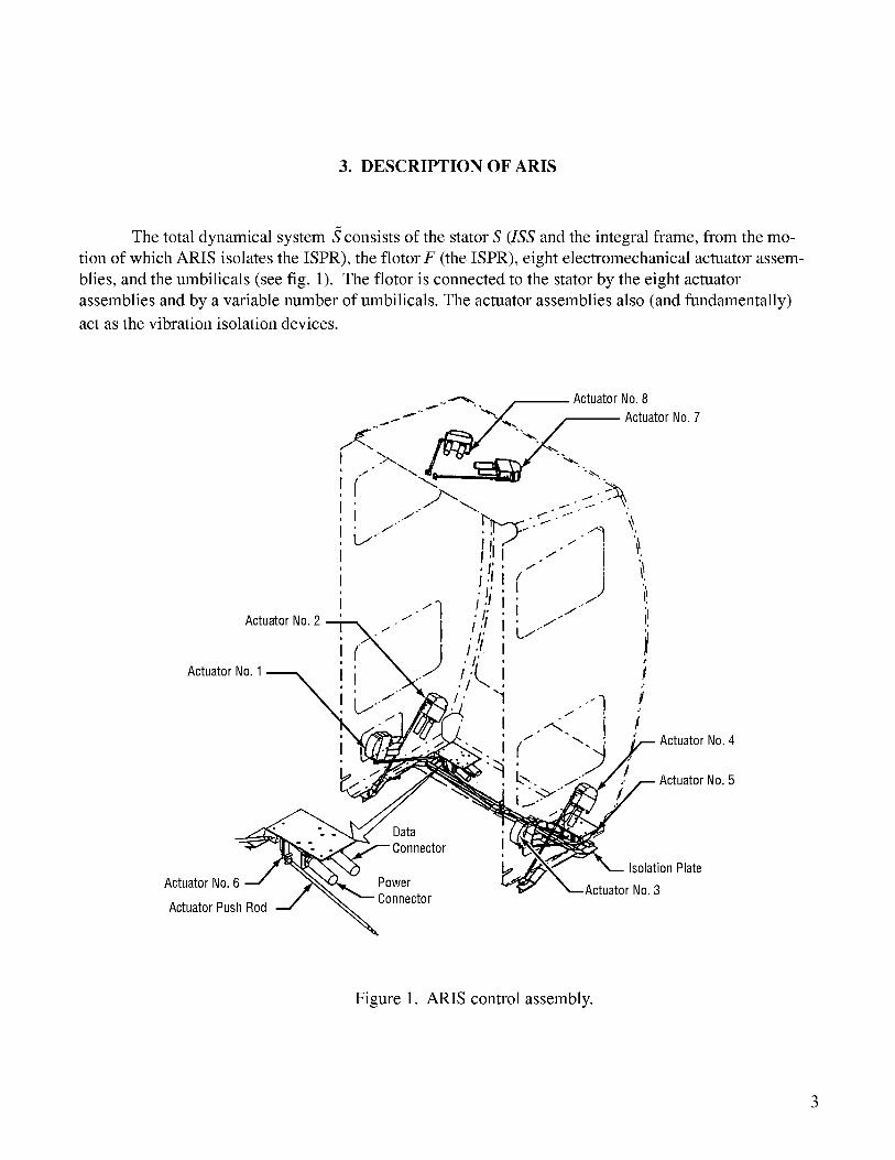
3. DESCRIPTION OF ARIS
The total dynamical system S consists of the stator S (ISS and the integral frame, from the mo-
tion of which ARIS isolates the ISPR), the flotor F (the ISPR), eight electromechanical actuator assem-
blies, and the umbilicals (see fig. 1). The flotor is connected to the stator by the eight actuator
assemblies and by a variable number of umbilicals. The actuator assemblies also (and fundamentally)
act as the vibration isolation devices.
ActuatorNo.8
"_" --,'".,-,--t "-/.,-_-- "'_- ,_,."_-_,.t_/I Actuator No. 7
i c.- i q _i o t" t ,
! I,'I .-- ! ilI
! _..._). . i!i "q 'iili! i_ActuatorNo.2 ' " "I I ,/£/ !
ActuatorNo.1 ..- .11'1,.,, !
!L,,,--_ / "1 _..'l _
_. i (" --_yActuatorNo. 4
. k'-, "" ActuatorNo.5i/...->-
__,r _ _. ^ ActuatorNo.
ata
-_v'_ Connector IsolationPlateActuatorNo.6 J _,,,_ Power 3
_ConnectorActuatorPushRod i/ om
Figure 1. ARIS control assembly.

Eachactuatorassemblyconsistsof aLorentz(voice-coil)actuator,anarm,anupperstinger,apush-rod,a lowerstinger,andapositionsensor.(Seefig. 2 for akinematicdiagramandfig. 3 for acomputer-aideddesign(CAD) drawingof a singleactuator.)Oneendof eachactuatorarmis connectedto theflotor throughacross-flexure,whichallowstheflotor a singlerotationaldegreeof freedom(DOF)with respectto thestator.Theotherendof thearmis connectedto oneendof thepush-rodthroughtheupperstinger,a wire of veryhightorsionalstiffness.Eachupperstingerprovidestwo rotationalDOF'sin bending.Theoppositeendof thepush-rodis connectedto thestatorthroughthelower stinger,anothershortwire thatallowsthreerotationalDOF's (twoin bending,onein torsion)with respectto S.
Lorentz Coil
Upper Stinger
l_ (Angles q_. q_)Arm l_ A
,---J A_ A* A_? "_
"_-_'_ "..___ Flotor JFi I
._/ Push RodCross Flexure_ I
(Angle q_) /,SO F, [p,
Rattlespace _Umbilical L i
S_ Si
LowerStinger(Angles q_, i iqs, q6 )
Figure 2. Kinematic diagram, including the ith actuator assembly and the umbilical.
4

FieldAssemblyCoilAssembly
PivotLink
2-DOFHingeCover
LEDPositionDetector 1-DOFHinge
Lens
3-DOFHingeandLaunchSleeve
Figure 3. A single ARIS actuator.
Each stinger is modeled as a massless spring. The umbilicals are also considered to be massless;
they are modeled together as a single, parallel spring-and-damper arrangement, attached at opposite ends
to stator and flotor, at effective umbilical attachment points S u and F u, respectively. This effective
umbilical applies both a force and a moment to the flotor. The force is assumed to act at point F u.
The stator, the flotor, and each actuator arm and push-rod are considered to be rigid bodies with
mass centers at points S*, F_ A_, and P_*, respectively. The superscript * indicates the mass center of the
indicated rigid body; the subscript i corresponds to the ith actuator (i = 1 ..... 8). All springs (cross
flexures and stingers) are assumed to be relaxed when the ISPR is centered in its rattlespace (the "home
position").

4. COORDINATE SYSTEMS
With the ISPR in the home position, fix eight right-handed, orthogonal coordinate systems in the
flotor, one at each of the cross-flexure centers. Let the ith coordinate system (i = 1.... , 8) have origin F i
located at the center of the ith cross flexure, with axis directions determined by an orthonormal set of
unit vectors y.(j = 1, 2, 3). (The overhat indicates unit length, the index i corresponds to the ith actuator
assembly, and the indexj distinguishes the three vectors.) Orient the unit vectors so that _'2 is along theAI
ith arm, toward the ith voice coil; f] is directed parallel to the other segment of the ith arm and toward
the upper stinger (which is located atA_); and _l3 is in the direction _l1 × _; (along the intersection of
the two cross-pieces of the ith cross-flexure).
^i (j = 1, 2, 3) in the arm of each actuator. LocateFix a similar right-handed coordinate system aj^i ^i
each system aj such that it is coincident with the corresponding flotor-fixed coordinate system f_j when
the flotor is in the home position.
^iAt the respective lower stingers (points Si), place eight push-rod-fixed coordinate systems _pj
^i Orient these 24 coordinate systems so that when theand eight stator-fixed coordinate systems s_j.
stingers are relaxed (i.e., with the ISPR in the home position), the coordinate directions/3 i. and £/. are: : --J -J i
coaligned for the ith actuator with t112 (along with _, in the home position) directed from S i toward AS.
Finally, define a primary, central, flotor-fixed, reference coordinate system with coordinate^i
directions _j. All other flotor-fixed coordinate systems _fj are assumed capable of being referenced
(e.g., by known direction cosine angles) to this system (see eq. (4)).
5. ROTATION MATRICES
^' o o ^i o o o
Let the a_; coordinate system rotate, relative to the f. coordinate system, through positive
angle q[ about the )_l axis. Similarly, let the orientation oftt_e h / coordinate system, relative to the ^i--3 -J . . . P---j
coordinate system, be described by consecutive positive rotations q_ (about the ___l1axis! and q_ (about
^_ coordinate^i coordinate system, relative to the s__jthe moved three-axis). Let the orientation of the pj
system, be described by consecutive positive rotations q_ (about the _ axis), q_ (about the moved two-
axis), and q_ (about the moved one-axis).
6

i i iLet cj and sj represent the cosines and sines of the respective angles qj. Then the rotation
matrices among the several coordinate systems for the ith actuator assembly are as follows:
il ;; ;;c4c5 s4c5i i i i i i i i i i i i ,,^i.
-s4c 6 + c4s5s 6 c4c6 + s4s5s 6 c5s6 _ _s2i i. i i i i i. i i i i i ,,^i.
s4s 6+c4s5c6 -c4s 6 + s4s5c 6 c5c6J[ Is3
(1)
and
c2c__2c_11e2_,[as 4 4 J[41
. . ' ]u'2 0//z;1_ 0 l JILl3
(2)
(3)
^i
Finally, define a rotation matrix between the eight flotor-fixed coordinate systems f_j
flotor-fixed reference coordinate system _)_j:
and the single
Z/2[IS' 1_'2/7_//LP"fl3 Lf31 fJ2
(4)
6. GENERALIZED COORDINATES FOR
iThe 48 angles qj are the generalized coordinates of the system. For the ith actuator, the six
associated generalized coordinates are as follows: q{ is the angle at the cross flexure of the ith actuator;
q_ and q_ are the angles at the upper stinger; and q_, q_, and q_ are the angles at the lower stinger.

7. GENERALIZED SPEEDS FOR
iDefine generalized speeds uj for the system as the time rate of change of the generalized coordi-
nates of S in the inertial reference frame:
i .i (forj = 1, 6; i 1, 8)uj = qj .... = ..... (5)
8. ANGULAR VELOCITIES OF REFERENCE FRAMES AND RIGID BODIES
Designate the reference frames corresponding to the stator, the ith push-rod, the ith arm, and the
flotor, by the symbols S, Pi, Ai, and F, respectively. Let Si and fig. represent, respectively, the
coordinate systems in S and/f" defined respectively by [ _ _ _]rand f-2 . Two
intermediate reference frames were introduced previously to permit describing the angular velocity of
each push-rod relative to the stator; designate those intermediate frames corresponding to the ith actuator
assembly by /?i and Qi. Another intermediate reference frame was previously introduced between
frames _ and _.; designate this by _..
Let each intermediate reference frame have a frame-fixed, dextral set of unit vectors. Indicate the
unit vectors for each of these frame-fixed coordinate systems by using the corresponding lowercase
letter ( _. corresponding to /)i, etc.). The following, then, give the expressions for the angular velocities
of the various reference frames and rigid bodies of S"
Fi o)A i i ^i: ul_f 3 , (6)
P/O) T/ i ^i (7)= u2P__ 1 ,
Ti ojAi i ^i (8)= u3t 3 ,
S i ojRi i ^i (9)= u 4s 3 ,
i ^i (10)Ri o)Qi = u5r 2 ,

Qi _Pi i ^i (11)= U6_q_1 •
Using the addition theorem for angular velocities, the angular velocities of the rigid bodies
of S are
S i o,)Ai i ^i i ^i i ^i i ^i i ^i= U2P__1 + u3t__3 + U4S__3 + u5r 2 + u6q 1 , (12)
and
S i O,)Pi = u i ^i i ^i i ^i_ 4s3 + u5r 2 + u6_ql , (13)
S i 09Fi i ^i i ^i i ^i i ^i i ^i i ^i= U2__ 1 + u3t 3 + U4S__3 + u5r 2 + u6q_l - ulf 3 • (14)
9. BASIC ASSUMPTIONS
In the subsequent development of the ARIS equations of motion, it is assumed that ARIS works
as intended; i.e., that the ARIS controller prevents the ISPR from exceeding its rattlespace constraints.i
It is also assumed that the small-angle approximations hold for angles qj. Angular velocities and angu-
lar accelerations are assumed to be small as well. This means that the use of first-order linear perturba-
tions will permit the full nonlinear equations of motion to be approximated accurately by a set of
first-order linear differential equations. Finally, it is assumed that the angular velocity of the stator is
negligible and that the stator translational velocities and accelerations are small.
10. LINEARIZED VELOCITIES OF THE CENTERS
OF MASS FOR THE RIGID BODIES OF
Represent by r AB the position vector from arbitrary point A to arbitrary point B. Define the
following position vectors using the indicated scalars:
rFiAi2 i ^i i ^i (15)_ = lla 2 + 1½a1 ,
rSiAi2 i ^i (16)_ = l_p 2 ,
r_SiPi i ^i (17)= p2_p 2 ,
9

and
i * i ^i (18)F_A2Ai = a_ a__ -k a2a 2 ,
rFiF*_=fil_ I +f__i 2 +fj__i3 . (19)
First-time derivatives of the appropriate position vectors, under the stated assumptions, yield
expressions for the velocities of the centers of mass for the 17 rigid bodies. The following expressions
are the linearized velocities for those centers of mass. (The presubscript indicates that the expressions
are linearized; the presuperscript indicates the reference frame assumed fixed for purposes of the
differentiations.)
z'. i( i^i _)St-ve_* = P2 -u4s-1 + u (i = 1 ..... 8) , (20)
* i i ^iSivAi =_ [-a_u_ - (a_ + l_ )u_ ]/3_+ (a_u_ + alu 4 )p__2+ [a_u_ _ alu5ii + (a_ + 13i)u 6i]P--3'^ i (21)
and
where
and
[11 11/ 1)1 11,1: fju 1-V2u 3- V l+l_ U4+V3u 5]el
+ [_flu_ _V_(ul +u_ )+V_(U_ +ul )]__I+[vlul _vlU51 l+(vl+l_)u6]p31 1 ^1 , (22)
v_ : fl / -l_ , (23)
v_: f_-l_ , (24)
11. LINEARIZED ACCELERATIONS OF THE CENTERS OF MASS
FOR THE RIGID BODIES OF
Taking the time derivatives of the respective linearized velocity vectors yields expressions
for the linearized accelerations of the centers of mass for each rigid body. Note that the linearized
velocity vectors may be used in this step--the full nonlinear accelerations need not be determined.
10

This is a tremendous savings of effort, which would not be afforded if Newton's Second Law were
applied directly instead of Kane's approach:
Si_aP/* i[ .i^i .i^i)=p2_-u4s 1 +u6s 3 , (26)
_ * .i ^i (a_it_+alu4)P_ 2SiaAi =[-a_tJ_-(a_+/_)u4]___l+ i.i _^i
and
[ i .i i.i ( i) .i ]^i (27)+ a2u 2-alu 5+ a_+l 3 u6 P3 '
• [11 11( 1)1= f2ul-V2U3- V1 +13 u4 +V3U5]__P1
•1 ^1+ [-_t_- V_(t_l + t_)+ V_(t_ + u4)]__p2
[11 1.1(1+ v2u 2-Vlu 5+ v + P--3 (28)
12. LINEARIZED PARTIAL VELOCITY VECTORS FOR THE POINTS OF
AT WHICH THE CONTACT/DISTANCE FORCES ARE ASSUMED TO ACT
The partial velocities and partial angular velocities are formed by inspection of the relevant
velocity vectors. These partial velocities are then (and the order here is crucial) linearized by neglecting
higher order terms.
12.1 Linearized Partial Velocities of P*
For the ith push-rod, the linearized partial velocities are
Si Pi/_vr =O(forr=l,2,3) , (29)
Si Pi* "( i ^i )IV4 :-p_ _ +q4/2 , (30)
and
_]* i i ^iSiv " =p2q6S__l , (31)
11

Si Pi* if i^i i^i _)lV__6 = p2_q5s_l-q6s_2 + _ .
12.2 Linearized Partial Velocities of A i
(32)
For the ith arm, the linearized partial velocities are
Siv_Ai =0 ,_ (33)
S}vA. i i ^i ( )--i3-a2q2p__ 2 + a_ i i= + alq 3 , (34)
S_v_A (ai2 i i)/31 ( i i_^i i i^i• i -}-alq 3 + a_ += _ alq2p 3 ,- a2q3 ]P2 (35)
S_A ( i)Ai( (.... ai2+a[q_+l_ el + a[ a2q3i i]p__2_^i a2q5ii +alq6i i +t3q5,i i]p__3_^i, (36)
and
Siv_A*. ( i i t i .,i i_^i i i^i ( i i ')/3i 3' = a2q 2 + a2q 6 -t-t3q6]__pl - alq6p__2 + a2q 3 - a_ ,
S_lv__ i i^i ( i i +l_)• " :-a2q2p 2 + a_ +alq 3 /3_
(37)
(38)
12.3 Linearized Partial Velocities of F*
For the flotor, the linearized partial velocities are
__1_*:sj__11_#_1_, (39)
- _ v3q2 ,,__- _q_+_ p_+ _q_+ - - f?q____ (40)
SI"F* ( 1 1-VI+flql]P__I+(V_ +f2ql]PP_2+Vlq2P__3_Vlq 3 _1 1_^1 1 1 _1 1_^1 . 1 1 ^1= _ v2q 3IV_3 (41)
Sll_4vF* : [-v_ q_ - vl + v_ (ql + q_ ) + fllq_ - 1_]/311
+(_111 11 _11,_1(11 11 11)_1- vlq 6 v2q5-v2q3 +v3q5 +32ql]___ 2 + +13q5 P--3 (42)
12

andS iv F* =[vl(ql+q_)+V_ .,1 1]^1_ 1 1^1 -(VI V2q311 ,q 1_^1_vlq6 P2 32 ql )P3I-5 + t3q6 ]--Pl - +
S1,F* (1 I+V_)( 1 I+V1 1 1 _)^1i__6 - V2q 2 E 1 + - __= Vlq3 V3q2 flq_ + 1 P--3
(43)
(44)
12.4 Linearized Partial Velocities of Fu
Since
Define measure numbers for r F Fu as follows:
"- _ _
IV-r = IV-r l[OU rk. -- -
(45)
(46)
the linearized partial velocities for the umbilical attachment point Fu can be expressed as follows:
S1" fu * ^1 ^1l±l =SllvF + YFuf l - XFuf 2 , (47)
S1FuS1.F* ( 1)^1 [ (I±2 - IV-2 ZFu + YFuq2 P2 + YFu + XFu q_ 1_ _. 1 ] ^1- _ - ql ) - LFuq2 ]P3 ' (48)
• [( ) ]AI[ ( 1)]A1 1A1SlvS:Slv( + XFu q_-q_ -YFu Pl + XFu+YFu q_-q3 P--2 + XFuq2P31--J l-- __ '(49)
S1,Fu-SI'F* [XFu(q_-q3)+ - _I_-4 - IV-4 + 1 ZFu(ql +q_) YFu]_ll
t t Z t] ^t t F.qSI___P3 '+[XF" +yF.(ql_q3)+ F.qs]p2__[XF.q6 +y 11^1 (50)
and
S1 Fu SIyF* YFu(ql+q6)]P_l-(SFuq6)P_2-[YFu(q_ q_)+ _
S1, Fu _S1. F* YFuq2 )P2 + [YFu + - - •I_-6 - I_-6 _(ZF u+ 1 ^1 XFu(q_ q_) ZFuql]___
(51)
(52)
13

12.5 Linearized Partial Velocities of F/
The linearized partial velocities of Fi are as follows:
:o_ (53)
i i ^iSi Fi -(l_ + 12q 3)a 3iv2 = (54)
S i Fi i^i i^iIV3 =/lal -12a2 , (55)
S iv_ =(l_-l_)a__+(l_q_-l_)a_i2+[l_q_+l_(q_+qi6)-,i i]^it3q5 ]a3 ,(56)
and
i_.,i i]__+ q_)__i2+(1 _ ,i i_^iS ilv_5F/= [_l_(q_ + q6 ]-e t3q 6 l_(q_+ - tlq3]_a 3
S_v__ i i^" (l_ )• . 13q2al2 i i i ^i= - + 12q 3 - 13 a_3 .
(57)
(58)
13. LINEARIZED PARTIAL ANGULAR VELOCITIES
FOR THE RIGID BODIES OF
The following are the linearized partial angular velocities for the system:
For the ith push-rod:
Si PilOJr = 0 (for r = 1, 2, 3) , (59)
Sico = s , (60)
and
for the ith actuator arm:
s}co = r , (61)
(62)
14
S}co Ai = 0 , (63)
(64)
^iS}co = t__3 , (65)
4A/̂ _sico = s_ , (66)
and
for the flotor:
sico = r ,
_i__2i:_01;
S1 oFl--1 = -al ,
(67)
(68)
(69)
S 1 O) ff ^1I--2 = P--1 ' (70)
l_3 = , (71)
SI o)F = _I--4 (72)
Slr.,F=_1I_---5 _-2 (73)
and
Si- Fl_ r = 0
S1 ,..,F ^1l _6 = q-1 '
(r = 1,...,6; i =2 ..... 8)
(74)
(75)
15

14. LINEARIZED ANGULAR ACCELERATIONS FOR THE RIGID BODIES OF
14.1 Linearized Angular Acceleration of Actuator Push-Rod P/
Si_P / .i ^i .i ^i .i ^i= u6_ 1 + u5_2 +u4p 3 •
14.2 Linearized Angular Acceleration of Actuator Arm _ii
• ' tji _ ^i•i ^i {ire+SinAi =(u_+u6)a l+tj_a_+_ 3 4)a3
14.3 Linearized Angular Acceleration of the Flotor
_ .i ^i .i ^i ' .i ^iSiaF =(l;t_ +u6)fl +u5f 2 +(-/)_ +/)_ +u4)f3 .
(76)
(77)
(78)
15. CONTRIBUTIONS TO THE SET OF GENERALIZED ACTIVE FORCES
DUE TO THE RIGID BODIES OF
15.1 Contributions Due to the Flotor
On orbit (i.e., neglecting the effects of gravity), the flotor is acted upon by forces and moments
due to each Lorentz coil, actuator arm, and umbilical, and by direct disturbances.
Let -F Ci and -m Ci represent, respectively, the force and moment exerted by the ith Lorentz coil
(located at A_) on the flotor,
where
assumed to act at point Fi, and
FF_.Ci = F Ci a__ , (79)
M Ci : r FiAi3 ME__ Ci :-FCi(l[--[-li4)(l_. (80)
16

Let F F/and__M F/ represent, respectively, the force and moment exerted by the ith actuator arm on
the flotor, at the ith cross-flexure. Since F F/ is a noncontributing force, it can be ignored in the analysis.
The total moment M F due to the eight cross-flexure springs has value
m F _ .i i _i= Xlql f_3 , (81)
i=1
where k_ is the ith cross-flexure spring stiffness.
Let F U and M U represent, respectively, the force and moment applied to the flotor by the umbilical,
where the force is assumed to act at flotor-fixed point Fu . Umbilical force F U is given by the equation
= - 1'1) 1+ -
+ (-k3x 3 -c3.r3)_3 +__Fb ; (82)
where __i is some appropriate stator-fixed coordinate system; Xl, X2, and X 3 are the umbilical elongations
respective __i(i = 1, 2, 3) directions; F b is the umbilical bias force in the home position; kl, k2,in the
and k 3 are umbilical spring stiffnesses; and c 1, c2, and c 3 are umbilical damping constants. Umbilical
moment __Mu is given by
M U = (-tCl¢ 1 - ?1¢1)__1 + (-tc202 - 72¢2)_ 2 + (-tc303 - 73¢3)_ 3 + M b , (83)
where ¢1, ¢2, and ¢3 are components of the umbilical angle of twist ¢ in the respective __i(i = 1, 2, 3)
directions; m b is the umbilical bias moment in the home position; _:1, _:2, and _3 are torsional umbilical
spring stiffnesses; and Y1, Y2, and Y3 are torsional umbilical damping constants.
Let f D and M D represent, respectively, the unknown disturbance force and moment acting on
the flotor. Assume FOto act through the flotor mass center F*. Define F/.D and M o to be the ith compo-
nents, respectively, of f o and M D, componentiated in F1.
In terms of the above, the flotor's contribution to the set of generalized active forces, for the rth
generalized speed, is
17

.I _ _D+ y_k'_q'_• S_a) F U+
$1 F M Ci1_ r "
Is .IV +- E _v__f* c_i=l
_ np's namelY, 1-r _ _.
The um. onS. The remaimng terms m ,. t
(s43
M..M_U,are addressed in the follOwing
_>2 -e<)-°'
_;_7t-v--<):°'
\i=x - '7
. , , .ll_\F,l) + {vII + llql)F#
&lEg . Ivl) = t-v2 + 12ql} '
s_m_,v_Y---_7 ,
(S5)
(g6)
(sg)
(89)
(9o)
(91-)
(92)
(93)
(94)
(95)
(96)
lg

(9"7)
(99)
(too)
0o1.)
(1.o_)
(1.o3)
0o_,)
{,1.o5)
(1.o6)
(1.07)
(.1.og)
1.9

I_5 Xlql./- 3 = 0 ,i=1
(109)
S1.F*.FD 1( 1 1)O (1 1 _)F2O ( 1 1 V1 ,d 1,tOIV-6 -- =V3 ql-q3 F1 + 13q2-V + l_+Vlq 3+ flql)r3 , (110)
S1 ,,.,F . M D S1 oF. M DI_6 -- = I--2 -- , (111)
S1 F/l_V6 '(-FCi) = 0 , (112)
and
S1 ,-.,F
8 i i ^i SI(Dff klqlf3S1 ,,.,F kl ql f3 I--2l_ 6 • = . .i= - i= -
(113)
(114)
Notice the coupling between the unknown-disturbance measure numbers and the generalized coordinates.
This coupling will make the disturbance input matrix E (in eq. (203)) time-varying.
15.2 Umbilical Force F U
Equation (82) expresses umbilical force F U in terms of umbilical-elongation components Xl, X2,
and x 3, and their time derivatives. These items must be reexpressed in terms of the generalized coordi-
nates and generalized speeds.
But
If the umbilical attachment point F u is at Fuh in the home position, then
xi =( r-SuE" --rSuf"h )'_i' (i= 1,2,3). (115)
rSuF. _ rSuFuh = rFuhFu = rS1F1 + rFf . _ rS1Su _ rSuFuh
where the right-hand-side terms can be expressed by
rSIF1 1 ^1 1 ^1 1 ^1_ = _ 11a__213P__2 - l__a1
(116)
(117)
20

^1(118)
and
pS1Su = Xsu_] .-[-YsuS_ 1 .-[- ZSu_
rSuF.,,=Xo*l+yo_ +_o*_
(119)
(120)
for appropriately defined coefficients.
Now, define the following rotation matrix:
{i1} 1112131i l_2 =/r21 r22 r23 _ •3 Lr31 r32 r33J[_ 1
(121)
In terms of the __i coordinate system, equation (116) can now be written in linearized form as
where
r_FuhFu = Xl_ 1 + X2__ 2 + X3_3(122)
for
Xl}[_11_12_131x2--/_1_2 _3/x3 Lr31 r32 r33J
Cl+YFu (q_ _q_ _ql)+zF uql _l_ql+ll(q_+ ql)]
_ -_ (q_+q_)-x_(q_-q_-q_)-,_(q_+q_)t_+(,lx,_)ql+(_,,1)(ql+q_)+,_q_I
C 1 = XFu - XSu - 11 _ x 0 ,
(123)
(124)
andc2 =YF.- ysu+l_-l_ - so ,
C 3=zFu-zSu-z 0 •
(125)
(126)
21

Differentiating,
1 1 1 1 1 1 1 1 1
IXlt [ rll r12 r13] |[ YFu(Ul-U3-U4)+ZFuU5-13u4+ll(U3+U4)l1 1 1 1 1 1 1_2 :/r21 r22 r23/ ]-ZFu(U2+U6)-XFu(Ul-U3-U4)-12(U3+U4 ) (127)1 1 1 1 1 1 1
x3 Lr31 r32 r33J [ (12-XFu)U5+(YFu-ll)(U2+U6)+13u6
Using equations (82) and (123)-(127), a linearized expression could now be written straightforwardly for
the umbilical force F U .
15.3 Umbilical Moment M U
Equation (83) expresses umbilical moment __MU in terms of angle-of-twist components 01, 02,
and 03, and their time derivatives. These items must be reexpressed in terms of the generalized coordi-
nates and generalized speeds.
Let 0 --@represent the rotation of the flotor, relative to the stator, from the home position. _@ is
the rotation axis, and ¢ is the angle of twist about that axis. Note that
0i = q} -fiq_' _i (i = 1, 2, 3) . (128)
Express _@ as
_@ = gl_ll +g2_12 +g3_13 . (129)
Define rotation matrix Q by
:iQllsl .l 51
(130)
22

The linearized 3×3 rotation matrix/Q has elements lQij defined as follows:
1_/'2--d - q]-4
For small ¢, it can be shown 13 that
-d+d+4 -q_11_14+4/_4_•
1 1-q_-q6 , J141(131)
[o ?-g2 IQ_IQT
¢ -g3 (1 _tr-_l/2 ,g2 -gl
(132)
where the post-superscript T indicates matrix transposition and tr IQ represents the trace of IQ" Substitu-
tion from equation (131) into equation (132), and simplification, yields
gl =_l'(q 1 +q_) , (133)
and
1 1g2 =-7'q5 , (134)
Q
-1 (q__q__ql4)g3= T • (135)
^1Substituting from equations (133)-(135) into equation (129), and transforming into the s__i coordinate sys-
tem by use of lQ, one obtains the following expression for the spin axis:
Since 1---¢has unit length,
1 1 1^1 1 1 _q4)_s3] "lh_¢=___[(q2+ql6)_]+q5s2_(ql_q3 1 ^1(136)
10= [(ql+ q_)2+ (ql)2+ (q__ q__ ql)2 ]1/2(137)
23

Use of equations (128) and (136) leads to the following linearized forms for angular position and rotation
rate:
and
03 lr31 r32 r33][-_ql-q3-q4)l
+= r23/1 1 1
q_3 Lr31 r32 r33] -|Ul-U3-U4
(138)
(139)
From equations (83), (138), and (139), a linearized expression could now be written straightfor-
wardly for the umbilical moment M U. The flotor's contribution to the set of generalized active forces
for the rth generalized speed could then be found by substituting the expressions for F U (sec. 15.2) and
M U into equation (84).
15.4 Contributions Due to the Actuator Arms
The forces and moments acting on the ith actuator arm are due to the respective Lorentz coil
(located at A_ ), the flotor (through the ith cross flexure), and the respective push-rod (through the upper
stinger). The coil force FCi is the only contributing force. The contributing loads, in the above indicated
order, are as follows:
F Ci = F Ci a__, assumed to act at point Fi, (140)
M_M_Ci = F_.FiAi3 x F__Ci = (l_ --}-li4 )_ x F Ci a_ = -F Ci (l_ --}-li4 )_ (141)
and
_MF/ .i i _.i_ =-Klqly__ 3 , (142)
l]/iAi .i i^i _i i ei (143)= -x2q2---Pl - K3q3 L3 ,
where l_ and l_ are pertinent geometric lengths, and k_ and k_ are pertinent upper-stinger spring stiffnesses.
24

In termsof theabove,thecontributionfor the ith actuator arm to the set of generalized active
forces for the rth generalized speed is
iQAi = S Fi FCi +S o)A i + _ MFi ) .IVr "-- l--r "( MAi MCi
The individual terms of the l oAi's are as follows:
S Fi .FCi =0IV_E1 _
S ,Ai.(MAi +MCi_MFi)=Oi_1 ....
S Fi. FCi = 0IE2 --
S ,A i + _mFi) i i__ = -k½q 2 ,l_ 2 • ( mAi mCi
S Fi.FCi =FCil_IV3 --
S o,)Ai MCi = klq 1 - k_q 3 1_ )I--3 "( M Ai + - M-M-Fi) i i i i _ FCi (1 _ +
S Fi .fCi ._fCi(l[_l_ )/v__4 _
So.)A i + _mFi) i i i i FCi(l[+l_ )I--4 "( M-M-Ai l_Ci = -klql - k3q3 ,
S Fi.FCi _FCi[l_(q_+q_)-l_q_]IV5 -- =
S o)A i M.._M__Ci M Fi F Ci (1_ .-b 1_ )(q_ q6),1_5 .(M_M_Ai_F _ )= 4-
(144)
(145)
and
(146)
(147)
(148)
(149)
(15o)
(151)
(152)
(153)
(154)
S F_. FCi = 0 (155)IV_6 --
S ,A i mCi -k2q2.ltU6 .(MA i + _MF/)= i i(156)
Notice the coupling between the control inputs and the generalized coordinates. This coupling will make
the disturbance input matrix B (in eq. (204)) time varying.
25

15.5 Contributions Due to the Push-Rods
The contributing loads on each push-rod are moments M P/and --1_ Ai , where (using pertinent
lower-stinger stiffnesses)
MPi .i i^i i i ^"_K4q4s_3 k_q5r_2 .i i^i__ = _ _ x6q6q 1 (157)
The contribution for the ith push-rod to the set of generalized active forces for the rth generalized
speed is
: lO)r .( M._M_Pi - l_Ai ) . (158)
The individual terms of the iQrPi's are as follows:
S e/109r '(MP/-MAi) =0 (r=1,2,3) , (159)
S e/1094 (MPi_MAi)= i i i i_ k3q3 - k_q 4 , (160)
and
s e/i095 .(M___Pi_MAi__)=_k5q 5i i , (161)
S e/1096 (MPi-MAi) = i i i i• k_q 2 - k_q 6 . (162)
16. CONTRIBUTIONS TO THE SET OF GENERALIZED INERTIA
FORCES DUE TO THE RIGID BODIES OF
,Ai/A[Represent (by *jk ) the central moment/product of inertia of the ith actuator arm for the j and
^i and _. Define push-rod inertias I_. i/Pi* analogously, where thek body-fixed coordinate directions aj
single subscript indicates that the axes are assumed to be principal axes. Let 1j.%/f*representr, the central
^1 ^1
inertia scalar of the flotor for the flotor-fixed coordinate directions _fj and fk" Use the symbol/-/to
represent an angular momentum vector. Associated post-superscripts on/-/have the same meanings as
for the inertias. The contributions to the generalized inertia forces for S can now be expressed.
26

16.1 Contributions Due to the Push-Rods
( *)P/toThe contributions 1Qr the generalized inertia forces due to the ith push-rod are as follows:
(IO;)P/ Si P/*'(-mp/S} aP/*'_S P/ (-l I:IP//P/*)= iV__r . _ )+lO__r • =0 (r=1,2,3;i=1 ..... 8) , (163)
* S. .* *
(IQI) Pi :s}v__Pi .(-mPi }a_p/ )+so3 Pi .(-ii2I Pi/Pi )
=- mP i P2 + I Pi it_ , (164)
= iV5 • . ,-t___P//P/ (165)
:-Imp/(p_)2 + Ip//P/*]it_. (166)
16.2 Contributions Due to the Actuator Arms
/ ,xA i
The contribution [1Qr ) to the generalized inertia forces due to the ith actuator arm for the rth
generalized speed is
(iQ;)Ai S i A; { Si_A;'_,S ,Ai (_li2iAi/A;)= iVr ._-mAi i_ )-i- i_ r • (167)
Then the individual, nonzero terms of the (,Q*)Ai's are as follows:
S}vA[ { SivA* {(a_) 2 +[a_(a_ +/_)1 i i .i ]•_-mAi lU__' )=-mAi t)_ t)_-ala2u5[ (168)
27

(169)
(170)
(171)
•[-mni ,__, )=-mni{[(a_)2+ a_(a_ it_ )2+ (a_ u_}(172)
I , (173)
S_vAi -mAi -mA i• __ -a,a2u2-a_(a_+'_)u_ (174)
(175)
and
S}v__2[ .(-mAiS}a A[ )=-mAi { a_(a_ + l_)ti_+ (a_+ l_)2 ti_ -a[(a_+ l_)ti_} ,
I.
(176)
(177)
16.3 Contributions Due to the Flotor
( ,)FThe contribution IQr to the generalized inertia forces for the rth generalized speed is
S1, F _rt_F S "_ S1 FIQr = l_r " i aF J+ if-Or" • (178)
28
(;)FThen the individual terms of the /Q 's are as follows:
,_. (_o_,_a__) sl ) ]ul + h v3u2
_1 1.1 + fl V3u6} ,+[<,,,;-sj,,_]u_-[,,j(,,_+,_)+,_,,,;]u_+,2_._,,, (179)
(180)
Sllv_ _mFSia F I" 1_1.1 2 2v + v 4 1 1.1 1 1.1• = _ v1v3u 3 - v1v3u 4
1 1.1 [( _)2 1(1 /_)]ti_},- v1v2u 5+ v + v 2 v 2+ (181)
I--2 - - , (182)
Silva* "(_mF S} a_F*) : -mF {[_fTV 1 - _Iv_ ]/_ _V1V3U2+I1.1 [(V_)2 +(V1 )2] tt_
[( )] ,,,,+ V_)2+VI(v 1+1_ {t I 1 1.1_V1V3u6- V2V3u 5 (183)
(184)
* (-mF S *)SllvF . ia F
--1 1.1 1 1.1 [(i) 2 1( _)]-71VlUl-VlV3U2+ V +V vl +I it_
[(Vi)2 (vl+l_)2]tt I V_(vl+l_)tt 1 1 1.1]+ + - _ v 1v3u6 _ '(185)
29

_F(,_F,F*)_; (,_F,F*)I-----4 = ' , (186)
* ( m SiaF*']= f_V3u 1 - VlV2U 2
_ 1 1 h__v3(v2 + (v_)2]hl_vi(vl+l_)hl6} ,_2_ ' ' ,_>_+[(_I)2+ (187)
S F (-I I2IF/F*) = -IF(F*(fti2+ {t_) 122"F/F*'iu5 123.F/F*[.i_u3 "i0,)5 • _ _ + ft_4- hi,!
(188)
and
+v v 1 + 13 u2 VlV 3_ _ VlV3U 4
(189)
(190)
17. EQUATIONS OF MOTION FOR THE SYSTEM
17.1 Kinematical Equations
There are 48 kinematical equations for the system, one for each generalized speed:
uj= ,(j=l ..... 6; i=1 ..... 8) . (191)
17.2 Dynamical Equations
Six dynamical equations are obtained using the following process. First, add the respective
contributions of the 17 rigid bodies to the set of holonomic generalized active and holonomic general-
ized inertia forces, for each generalized speed (i.e., r = 1..... 48). The holonomic generalized active
force for the rth generalized speed is
30

17FF= (FF);
j=l(192)
where (F r) J is the contribution to the set of holonomic generalized active forces due to the flh rigid
body. That is,
8 8Fr = lQf -'[- £ IQ Ai -'[- £ IQE ei
i=1 i=1
Likewise, the contribution to the set of holonomic generalized inertia forces is
(193)
F 2 _ (F2) j (IQ;) Fq- _' *\Ai= [IOr) + _1 *\Pi= (tOt)j=l i=1 i=1
(194)
Second, develop the relationship between the dependent and the independent generalized speeds in the
form
i= 6uj _, Arsuls+Br (i=2 ..... 8;j=l ..... 6;r=7 ..... 48) , (195)
s=l
iwhere the factors u_ are the six independent generalized speeds, and the terms uj are the 42 dependent
generalized speeds. Ars and B r are scalars, derived from the nonholonomic constraint equations (see
sec. 17.3). The nonholonomic and holonomic generalized active forces are related to each other as
follows:
48fr = fr + 2 fsAsr (r = 1..... 6) . (196)
S=7
Similarly, the nonholonomic and holonomic generalized inertial forces are related to each other as follows:
~, , 48 ,Fr =F r + _. FsAsr(r=l ..... 6) .
S=7
Kane's dynamical equations,* then, are
(197)
Fr+F*:0(r=l ..... 6). (198)
* This step was erroneously omitted in references 10 and 11, resulting in incorrect incorporation of system constraints. The authors
discovered and corrected the error during the course of model verification.
31

17.3 Constraint Equations
The kinematical and dynamical equations together are 54 in number: 48 kinematical and 6
dynamical. Since the complete set of equations for an n-degree-of-freedom system numbers 2n, and
since the system S has 48 degrees of freedom, 42 more equations are needed to describe completely the
motion of the system. These missing equations are the holonomic constraint equations (in nonholonomic
i (i=2, 8; j=l ...6).form) for the dependent generalized speeds uj .....
Since the velocity and angular velocity of the flotor center of mass F* is the same irrespective of
the actuator path chosen for describing its position, a set of constraint equations can be written in vector
form using the following:
and
Xivi* = (XidrXiF* I'_ Sj F* (i=l,j=2 ..... 8) , (199)
S * S *i09F : J)09 F (i = 1, j = 2 ..... 8) . (200)
If one expands equation (199) and resolves them into a common coordinate system (here, the _i coordi-
nate system), one obtains the following 21 (motion) constraint equations:
i i i i-v3f}j + v2f_j
• " i i-,41h +vll j- +i i i i
u3ffj - ulf_j
li )_ ii i (V_ + 3 J3j-v3f}j +
F
4
u_
1 1 1 1-v3fJj + v2fJj
1 1 1 1V3flj - Vlf_j
1 +8)lJ;-v3fJj +
r _ .
<
.I
_H_.
(i=2 ..... 8;j=1,2,3) , (201)
Similarly, if one expands equation (200) and resolves them into a common coordinate system (here again,
the _i coordinate system), one obtains the remaining 21 (motion) constraint equations:
32

- i-f_j
T - . - 1
44
T
1u2
4<
1u4
1_u6.
_, (i=2 ..... 8;j=1, 2, 3) (202)
(It should be noted here that, although equations (201) and (202) are in nonholonomic form, the constraints
they represent are actually geometric.)
18. STATE-SPACE FORM OF THE EQUATIONS OF MOTION
The time derivatives of the constraint equations can be used with the constraint equations them-
selves, to write the kinematical and dynamical equations (eqs. (191) and (198), respectively) in the
following descriptor form:
[-I
IO v/ IK
The state vector consists of the 48 coordinates q and the six independent generalized speeds ul, where
ul ul ul ua] (204)
The constant matrices M, K, and C are system mass, stiffness, and damping matrices, respectively. The
symbols I and O represent, respectively, an identity matrix and a zero matrix of appropriate dimensions;
vector i contains the eight control currents to the Lorentz coils; and vector d is the disturbance vector.
The input matrices B and E are time-varying matrix functions of the coordinates. N is a constant matrix
that incorporates the kinematical equations; N and C together incorporate the holonomic constraints.
The disturbance term [E] {d} accounts for the umbilical bias force F b and moment __Mb, and the
unknown direct disturbance force f o and moment M o. Recall that in the development of the foregoing
equations the angular acceleration of the stator was assumed to be negligible. However, the translational
acceleration of the stator, although presumably unknown, cannot be neglected. In fact, that acceleration
33

is the source of the umbilical contribution to flotor g-jitter. To include this indirect disturbance
contribution, one must add an (unknown) indirect acceleration disturbance term a/to each of
equations (26)-(28). Along with the other disturbances, this indirect disturbance will appear in the final
term of equation (203).
19. MODEL VERIFICATION
AUTOLEV TM software, marketed by Online Dynamics, Inc., was used to create a full nonlinear
model of ARIS including the actuator (rigid-body) dynamics. 14 AUTOLEV was then used to develop
and verify the linearized equations presented in this paper.
An independent model was developed using the DENEB Envision software, with current CAD
models of an ARIS-outfitted ISPR. 14 This model was used as an independent (static) check of the
actuator kinematics.
For dynamic validation, various loads were applied to the flotor, and the nonlinear AUTOLEV
model was allowed to move in simulated response. Motions were permitted which greatly exceeded the
rattle space constraints (with angles permitted up to =90°), to test thoroughly the nonlinear model. The
six angles for a single actuator (AUTOLEV model) were inserted into the Envision model, and the
remaining 42 actuator angles were compared between the two nonlinear models. The respective angles
were in consistent agreement, even with these large motions, to within less than half a degree.
20. FUTURE WORK
The next tasks will be the addition of umbilical forces to the AUTOLEV equations, the imple-
mentation of a linearized model in MATLAB ®, and MATLAB model verification. The verification
procedure will first entail comparing the eight position vectors from a common point on the stator to the
flotor center of mass, as traced through the eight actuators, with the flotor centered in its home position.
Then the procedure will be repeated with the flotor moved statically from its home position, in six
degrees of freedom.
For dynamic verification, various loads will be applied to the flotor to verify that the eight
position vectors track for motion inside the rattlespace (i.e., small angles). Simulations of the nonlinear
AUTOLEV model will be compared with simulations of linearized system models (one with and one
without actuator dynamics) to determine the simplest model suitable for controller design.
System dynamics will be incorporated into the Envision model, along with the capability of
state-space, discrete time control. The MATLAB and Envision models will then be available, respectively,
for centralized, state-space/optimal controller design and for closed-loop system simulation.
34

REFERENCES
°
°
°
°
°
°
°
°
°
10.
11.
12.
13.
14.
DeLombard, R.; Bushnell, G.S.; and Edberg, D.: "Microgravity Environment Countermeasures
Panel Discussion," AIAA 97-0351, January 1997.
"System Specification for the International Space Station," Specification SSP41000, Rev. D,,
NASA Johnson Space Center, Nov. 1, 1995.
DelBasso, S.: "The International Space Station Microgravity Environment," A/AA 96-0402,
January 1996.
Nelson, E.S.: "An Examination of Anticipated g-Jitter on Space Station and Its Effects on Mate-
rials Processes," NASA TM-103775, April 1991.
Edberg, D.; et al.: "Results of the STABLE Microgravity Vibration Isolation Flight Experiment,"
Guidance and Control, Vol. 92, pp. 567-581, 1996.
Whorton, M.S.: "g-LIMIT: A Vibration Isolation System for the Microgravity Science
Glovebox," presented to the 17th Microgravity Measurements Group Meeting, March 1998.
Hampton, R.D.; et al.: "The Microgravity Vibration Isolation Mount: A Dynamic Model for
Optimal Controller Design," Proceedings of the MAG '97 Industrial Conference and Exhibition,
pp. 220-230, August 1997.
Bushnell, G.: "STS-79 Final Report, RME-1313/ARIS," Boeing Document SK683-61855-1,
December 1996.
Kane, T.R.; and Levinson, D.A.: Dynamics: Theory and Applications, McGraw-Hill, Inc., New
York, 1985.
Hampton, R.D.; et al.: "A High-Fidelity Dynamic Model for the Active Rack Isolation System,"
AIAA 98-0458, January 1998.
Hampton, R.D.; and Beech, G.S.; "A 'Kane's Dynamics' Model for the Active Rack Isolation
System," IMECE DSC-7B-5, November 1999.
Kane, T.R.; and Levinson, D.A.: "Formulation of Equations of Motion for Complex Aircraft,"
Journal of Guidance and Control, Vol. 3, No. 2, pp. 99-112, April 1979.
Greenwood, D.T.: Principles of Dynamics, 2rid ed., Prentice Hall, Englewood Cliffs, New Jersey,
1988.
Beech, G.; and Hampton, R.D.: "Validation of a 'Kane's Dynamics' Model for the Active Rack
Isolation System," AIAA 2000-0682, January 2000.
35

REPORT DOCUMENTATION PAGE Form ApprovedOMB No. 0704-0188
Public reporting burden for this collection of information is estimated to average 1 hour per response, including the time for reviewing instructions, searching existing data sources,gathering and maintaining the data needed, and completing and reviewing the collection of information. Send comments regarding this burden estimate or any other aspect of thiscollection of information, including suggestions for reducing this burden, to Washington Headquarters Services, Directorate for Information Operation and Reports, 1215 JeffersonDavis Highway, Suite 1204, Arlington, VA 22202-4302, and to the Office of Management and Budget, Paperwork Reduction Project (0704-0188), Washington, DC 20503
1. AGENCY USE ONLY (Leave Blank) 2. REPORT DATE 3. REPORT TYPE AND DATES COVERED
May 2001 Technical Memorandum5. FUNDING NUMBERS4. TITLE AND SUBTITLE
A "Kane's Dynamics" Model for the Active Rack Isolation System
6. AUTHORS
R.D. Hampton,* G.S. Beech, N.N.S. Rao,* J.K. Rupert,* and Y.K. Kim
7. PERFORMING ORGANIZATION NAMES(S) AND ADDRESS(ES)
George C. Marshall Space Flight Center
Marshall Space Flight Center, AL 35812
9. SPONSORING/MONITORING AGENCY NAME(S) AND ADDRESS(ES)
National Aeronautics and Space Administration
Washington, DC 20546 0001
8. PERFORMING ORGANIZATIONREPORT NUMBER
M 1019
10. SPONSORING/MONITORING
AGENCY REPORT NUMBER
NASA/TM 2001 211063
11. SUPPLEMENTARY NOTES
Prepared by Engineering Systems Department
*University of Alabama in Huntsville, Huntsville, Alabama
12a. DISTRIBUTION/AVAILABILITY STATEMENT
Unclassified-Unlimited
Subject Category 31
Nonstandard Distribution
12b. DISTRIBUTION CODE
13. ABSTRACT (Maximum 200 words)
Many microgravity space science experiments require vibratory acceleration levels unachievable without
active isolation. The Boeing Corporation's Active Rack Isolation System (ARIS) employs a novel
combination of magnetic actuation and mechanical linkages to address these isolation requirements on the
htternational Space Station (ISS). ARIS provides isolation at the rack (International Standard PayloadRack (ISPR)) level.
Effective model-based vibration isolation requires (1) an appropriate isolation device, (2) an adequate
dynamic (i.e., mathematical) model of that isolator, and (3) a suitable, corresponding controller. ARIS
provides the ISS response to the first requirement. This paper presents one response to the second, in a
state space framework intended to facilitate an optimal-controls approach to the third. The authors use"Kane's Dynamics" to develop a state-space, analytical (algebraic) set of linearized equations of motionfor ARIS.
14. SUBJECT TERMS
Active Rack Isolation System, control, dynamics, International Space Station
17. SECURITY CLASSIFICATION
OF REPORT
Unclassified
NSN 7540-01-280-5500
15. NUMBER OF PAGES
4816. PRICE CODE
18. SECURITY CLASSIFICATION 19. SECURITY CLASSIFICATION 20. LIMITATION OF ABSTRACT
OF THIS PAGE OF ABSTRACT
Unclassified Unclassified Unlimited
Standard Form 298 (Rev. 2-89)Prescribedby ANSI Std. 239-18298-102