a fuzzy controlled pwm current source inverter for wind...
TRANSCRIPT

International Journal of Smart Electrical Engineering, Vol.3, No.2, Spring 2014 ISSN: 2251-9246 EISSN: 2345-6221
107
A Fuzzy Controlled PWM Current Source Inverter for Wind
Energy Conversion System
Mehrnaz Fardamiri1, Shahram Javadi
2, Seyed Zeinolabedin Moussavi
3,
1 Electrical Engineering Department, Central Tehran Branch, Islamic Azad University, [email protected] 2Assistant Professor, Central Tehran Branch, Islamic Azad University, [email protected]
3 Faculty of Electrical and Computer Engineering Shahid Rajaee Teacher Training university, Tehran, Iran, [email protected]
Abstract
In this paper, a fuzzy controller is proposed to control the current source inverter (CSI) in a wind energy conversion system
(WECS) based on permanent magnet synchronous generator (PMSG). The fuzzy controller guarantees the unity power factor
operation of CSI. In order to drive CSI the space vector switching (SVM) is utilized. In addition, the WECS has a buck
converter which regulates the DC current so that the maximum power point tracking is achieved. The proposed system is
implemented in MATLAB/SIMULINK, and the results are provided and compered with the traditional PI controller based
systems. The results show that the proposed system is faster than traditional PI controller based systems.
Keywords: Fuzzy Controller, Current Source Inverter, PMSG, WECS.
© 2014 IAUCTB- IJSEE Science. All rights reserved
1. Introduction
In recent years, there has been a fast growth in
wind energy conversion system (WECS). There are
two general types of wind turbines in WECS: fixed
speed wind turbines and varying speed wind turbines
[1]. Permanent magnet synchronous generator
(PMSG) is one of the most attractive generators for
the varying speed turbine WECS. The high
efficiency and elimination of the gear box, are two
advantages of these electrical machines which has
attracted the attention of many researchers. Voltage
source inverter (VSI) is the most conventional
topology for WECS. However, current source
inverter (CSI) topology has been recently became a
good alternative for VSI. Some of the attracting
features of CSI are high power density, simple
control schemes (compared to VSI) and low
harmonic output voltage waveform [2].
There are some topologies for CSI used in
WECS. In [3] the authors proposed a topology which
uses a PWM current source rectifier (CSR) and
PWM current source inverter (CSI). This topology
has a better control performance but is some
expensive case. Another topology which uses a diode
rectifier and thyristor inverter is proposed in [4]. In
this case the reliability is increased and the cost is
decreased. However, the lack of reactive power
control and poor grid waveforms make it a less
proper choice for modern WECS.
In [5] the authors proposed a topology composed
of a full scale PWM CSI with a diode rectifier and a
buck converter. In this configuration, both the active
and reactive powers that are transferred to the
network could be controlled. The traditional PI
controllers are used for MPPT and unity power factor
operation. However, the controller responses are
some slow and the control signals are very turbulent
pp.107:112
International Journal of Smart Electrical Engineering, Vol.3, No.2, Spring 2014 ISSN: 2251-9246 EISSN: 2345-6221
108
due to system non-linearity and malfunctioning of
traditional PI controllers.
In this paper, a fuzzy controller is proposed to
control CSI in a WECS with PMSG. The fuzzy
controller guarantees the unity power factor
operation of CSI and has a fast response to the
system perturbations. In order to drive CSI the space
vector switching (SVM) is utilized. The proposed
system is implemented in MATLAB/SIMULINK,
and the results are provided and compered with the
traditional PI controller based systems.
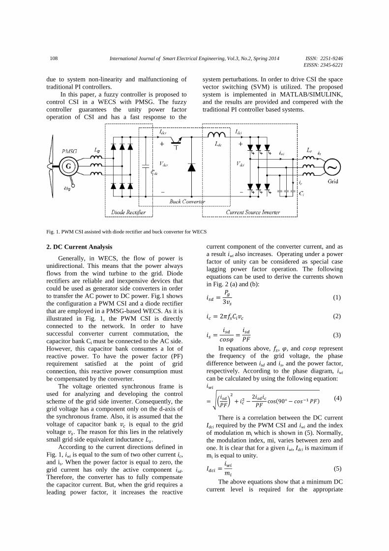
Fig. 1. PWM CSI assisted with diode rectifier and buck converter for WECS
2. DC Current Analysis
Generally, in WECS, the flow of power is
unidirectional. This means that the power always
flows from the wind turbine to the grid. Diode
rectifiers are reliable and inexpensive devices that
could be used as generator side converters in order
to transfer the AC power to DC power. Fig.1 shows
the configuration a PWM CSI and a diode rectifier
that are employed in a PMSG-based WECS. As it is
illustrated in Fig. 1, the PWM CSI is directly
connected to the network. In order to have
successful converter current commutation, the
capacitor bank Ci must be connected to the AC side.
However, this capacitor bank consumes a lot of
reactive power. To have the power factor (PF)
requirement satisfied at the point of grid
connection, this reactive power consumption must
be compensated by the converter.
The voltage oriented synchronous frame is
used for analyzing and developing the control
scheme of the grid side inverter. Consequently, the
grid voltage has a component only on the d-axis of
the synchronous frame. Also, it is assumed that the
voltage of capacitor bank is equal to the grid
voltage . The reason for this lies in the relatively
small grid side equivalent inductance . According to the current directions defined in
Fig. 1, iwi is equal to the sum of two other current ic,
and is. When the power factor is equal to zero, the
grid current has only the active component isd.
Therefore, the converter has to fully compensate
the capacitor current. But, when the grid requires a
leading power factor, it increases the reactive
current component of the converter current, and as
a result iwi also increases. Operating under a power
factor of unity can be considered as special case
lagging power factor operation. The following
equations can be used to derive the currents shown
in Fig. 2 (a) and (b):
(1)
(2)
(3)
In equations above, , , and represent
the frequency of the grid voltage, the phase
difference between isd and is, and the power factor,
respectively. According to the phase diagram, iwi
can be calculated by using the following equation:
√( )
( ) (4)
There is a correlation between the DC current
Idci required by the PWM CSI and iwi and the index
of modulation mi which is shown in (5). Normally,
the modulation index, mi, varies between zero and
one. It is clear that for a given iwi, Idci is maximum if
mi is equal to unity.
(5)
The above equations show that a minimum DC
current level is required for the appropriate
International Journal of Smart Electrical Engineering, Vol.3, No.2, Spring 2014 ISSN: 2251-9246 EISSN: 2345-6221
109
operation of the active and reactive power controls.
The level of this DC current also depends on the
value of Ci which is typically within the range of
0.3 to 0.6 for drives of medium voltage [1].
3. Proposed Control Scheme
The PWM CSI and the buck converter use the
same DC link inductor Ldc, whereas its filter
capacitor Cdc is responsible for smoothing out the
output of the diode rectifier. To obtain the desired
dc current level for the grid operation, the converter
amplifies the diode rectifier output current which
has relatively low values.
In the grid voltage oriented synchronous frame,
the q-axis component of the grid voltage, vsq,
becomes equal to zero; therefore, the magnitude of
the grid voltage becomes equal to its d-axis
component, vsd. Following equations can be used to
calculate the active and reactive powers of the grid:
( ) (6)
( ) (7)
The power requirements of the grid determine
the DC current reference. Using equations (6) and
(7), the active and reactive power references can be
converted into grid d- and q-axis current references.
The current references of the converter are provided
by the sum of the calculated capacitor current and
grid reference currents. Assuming that modulation
index, mi, is kept at its maximum value which is
equal to unity, then the reference current can be
derived using (4).
Fuzzy control provides a formal methodology
for representing, manipulating, and implementing a
human’s heuristic knowledge about how to control
a system. In this paper we uses a fuzzy logic based
controller in order to control the grid side converter.
The active power output control is responsible for
regulating the DC current therefore. The fuzzy
controller provides the reference for adjusting the
active current of the grid, isd. The fuzzy rules are
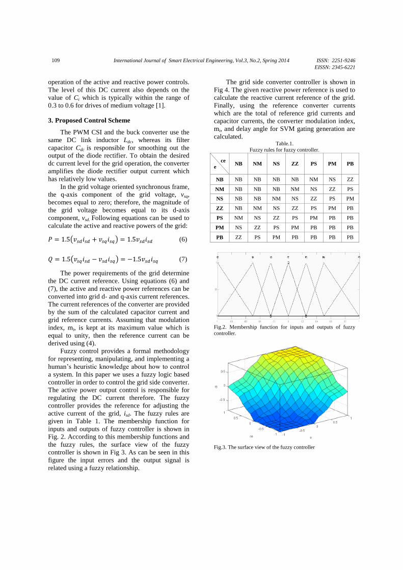
given in Table 1. The membership function for
inputs and outputs of fuzzy controller is shown in
Fig. 2. According to this membership functions and
the fuzzy rules, the surface view of the fuzzy
controller is shown in Fig 3. As can be seen in this
figure the input errors and the output signal is
related using a fuzzy relationship.
The grid side converter controller is shown in
Fig 4. The given reactive power reference is used to
calculate the reactive current reference of the grid.
Finally, using the reference converter currents
which are the total of reference grid currents and
capacitor currents, the converter modulation index,
mi, and delay angle for SVM gating generation are
calculated. Table.1.
Fuzzy rules for fuzzy controller.
PB PM PS ZZ NS NM NB ce
e
ZZ NS NM NB NB NB NB NB
PS ZZ NS NM NB NB NB NM
PM PS ZZ NS NM NB NB NS
PB PM PS ZZ NS NM NB ZZ
PB PB PM PS ZZ NS NM PS
PB PB PB PM PS ZZ NS PM
PB PB PB PB PM PS ZZ PB
Fig.2. Membership function for inputs and outputs of fuzzy
controller.
Fig.3. The surface view of the fuzzy controller
International Journal of Smart Electrical Engineering, Vol.3, No.2, Spring 2014 ISSN: 2251-9246 EISSN: 2345-6221
110
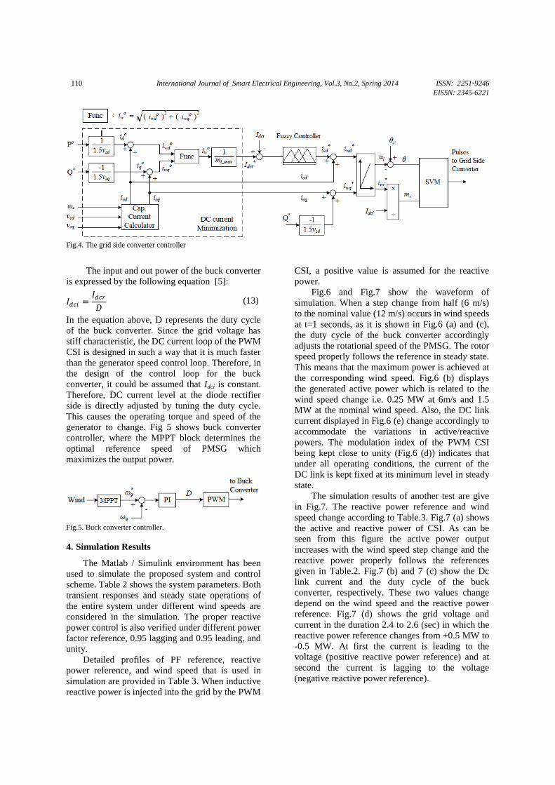
Fig.4. The grid side converter controller
The input and out power of the buck converter
is expressed by the following equation [5]:
(13)
In the equation above, D represents the duty cycle
of the buck converter. Since the grid voltage has
stiff characteristic, the DC current loop of the PWM
CSI is designed in such a way that it is much faster
than the generator speed control loop. Therefore, in
the design of the control loop for the buck
converter, it could be assumed that Idci is constant.
Therefore, DC current level at the diode rectifier
side is directly adjusted by tuning the duty cycle.
This causes the operating torque and speed of the
generator to change. Fig 5 shows buck converter
controller, where the MPPT block determines the
optimal reference speed of PMSG which
maximizes the output power.
Fig.5. Buck converter controller.
4. Simulation Results
The Matlab / Simulink environment has been
used to simulate the proposed system and control
scheme. Table 2 shows the system parameters. Both
transient responses and steady state operations of
the entire system under different wind speeds are
considered in the simulation. The proper reactive
power control is also verified under different power
factor reference, 0.95 lagging and 0.95 leading, and
unity.
Detailed profiles of PF reference, reactive
power reference, and wind speed that is used in
simulation are provided in Table 3. When inductive
reactive power is injected into the grid by the PWM
CSI, a positive value is assumed for the reactive
power.
Fig.6 and Fig.7 show the waveform of
simulation. When a step change from half (6 m/s)
to the nominal value (12 m/s) occurs in wind speeds
at t=1 seconds, as it is shown in Fig.6 (a) and (c),
the duty cycle of the buck converter accordingly
adjusts the rotational speed of the PMSG. The rotor
speed properly follows the reference in steady state.
This means that the maximum power is achieved at
the corresponding wind speed. Fig.6 (b) displays
the generated active power which is related to the
wind speed change i.e. 0.25 MW at 6m/s and 1.5
MW at the nominal wind speed. Also, the DC link
current displayed in Fig.6 (e) change accordingly to
accommodate the variations in active/reactive
powers. The modulation index of the PWM CSI
being kept close to unity (Fig.6 (d)) indicates that
under all operating conditions, the current of the
DC link is kept fixed at its minimum level in steady
state.
The simulation results of another test are give
in Fig.7. The reactive power reference and wind
speed change according to Table.3. Fig.7 (a) shows
the active and reactive power of CSI. As can be
seen from this figure the active power output
increases with the wind speed step change and the
reactive power properly follows the references
given in Table.2. Fig.7 (b) and 7 (c) show the Dc
link current and the duty cycle of the buck
converter, respectively. These two values change
depend on the wind speed and the reactive power
reference. Fig.7 (d) shows the grid voltage and
current in the duration 2.4 to 2.6 (sec) in which the
reactive power reference changes from +0.5 MW to
-0.5 MW. At first the current is leading to the
voltage (positive reactive power reference) and at
second the current is lagging to the voltage
(negative reactive power reference).

International Journal of Smart Electrical Engineering, Vol.3, No.2, Spring 2014 ISSN: 2251-9246 EISSN: 2345-6221
111
Table.2.
System parameters used in the simulation.
Generator parameters (Rated, pu based on generator side)
Apparent Power 2 MVA 1 pu
Stator phase voltage 1732 V (rms) 1 pu
Stator current 513 A (rms) 1 pu
Frequency 11 Hz 1 pu
Power factor 0.75 1 pu
Pole pairs 30 1 pu
Magnetic flux linkage
37.7 Wb (rms) 1 pu
19.4 mH 0.398 pu
DC link parameters (pu based on generator side)
2100 μF 1 pu
48.8 mH 1 pu
Grid side parameters (Rated, pu based on grid side)
Apparent Power 1.5 MVA
Phase voltage 1732 V (rms) 1 pu
Line current 405 A (rms) 1 pu
Power factor 0.95
Frequency 60 Hz 1 pu
1.08 mH 0.12 pu
471 μF 0.6 pu
Table.3.
Wind speed, PF and reactive power references
Time
Duration (s) 0-0.5 0.5-1 1-1.5 1.5-2 2-2.5 2.5-3
Wind Speed
(m/s) 6 12
Qref (MW) 0.5 -0.5 0 0 0.5 -0.5
(a) Wind turbine and rotor speed
(b) Grid active and reactive powers
(c) Duty cycle of the buck converter
(d) Modulation index of the PWM CSI
(e) The DC link current
Fig.6. Simulation waveforms under various wind speeds and
power factor requirements.
(a) Grid active and reactive powers
(b) The DC link current
(c) Duty cycle of the buck converter
(d) Grid voltage and current waveforms at 12m/s
Fig.7. Simulation waveforms of grid voltage and current under
various wind speeds and power factor requirements
0 0.5 1 1.5 2 2.5 3 3.5 4 4.5 5-30
-20
-10
0
10
20
30
Time(sec)
Sp
eed
of
Tu
rb
ine
0 0.5 1 1.5 2 2.5 3 3.5 4 4.5 5-1
-0.5
0
0.5
1
1.5
x 106
Time(sec)
P &
Q(W
/VA
R)
Active Power(P)
Reactive Power(Q)
0 0.5 1 1.5 2 2.5 3 3.5 4 4.5 50
0.1
0.2
0.3
0.4
0.5
0.6
0.7
Time(sec)
Du
ty C
ycle
0 0.2 0.4 0.6 0.8 1 1.2 1.4 1.6 1.8 20
0.2
0.4
0.6
0.8
1
Time(sec)
mo
du
lati
on
in
dex
0 0.5 1 1.5 2 2.5 3 3.5 4 4.5 50
100
200
300
400
500
600
700
Time(sec)
Idc(A
)
0 0.5 1 1.5 2 2.5 3-1
-0.5
0
0.5
1
1.5
2x 10
6
Time(sec)
P Q
&(W
/VA
R)
P
Q
Qref
0 0.5 1 1.5 2 2.5 3-100
0
100
200
300
400
500
600
700
800
Time(sec)
Idci(
A)
0 0.5 1 1.5 2 2.5 30
0.1
0.2
0.3
0.4
0.5
0.6
0.7
0.8
Time(sec)
Du
ty C
ycle
2.4 2.42 2.44 2.46 2.48 2.5 2.52 2.54 2.56 2.58 2.6-1.5
-1
-0.5
0
0.5
1
1.5
Time(sec)
Vs &
Is (
pu
)
Vs Is
PF: Lead
l
PF: Lag

International Journal of Smart Electrical Engineering, Vol.3, No.2, Spring 2014 ISSN: 2251-9246 EISSN: 2345-6221
112
5. Conclusion
In this paper, a fuzzy control scheme is
developed for PMGS-based WECS configuration
so that it can achieve maximum power tracking
from the fluctuating wind and grid power factor
control requirements (unity, leading or lagging).
Moreover, in order to decrease the total power loss,
the operating DC current in the PWM CSI is
minimized. Simulation results revealed that the
proposed configuration and control scheme has an
appropriate performance.
References
[1] W. W. E. Association, "World Wind Energy Report 2008," WWEA, Bonn, 2009.
[2] B. Wu, “High-power Converters and AC Drives”, John
Wiley & Sons, 2006.
[3] J.Nasiri, “Feasibility of Biogas Plant in Saveh City”,
www.SID.ir, 2008 .
[4] J. Dai, D. Xu, and B. Wu, “A Novel Control System for Current Source Converter Based Variable Speed PM Wind
Power Generators”, Power Electronics Specialists
Conference, PESC, IEEE, pp.1852-1857, 2007.
[5] X. Tan, J. Dai, and B. Wu, “A Novel Converter
Configuration for Wind Applications Using PWM CSI with
Diode Rectifier and Buck Converter”, IEEE Electric Machines & Drives Conference (IEMDC), pp.359-364,
2011.