a cell theory for stage iv work hardening of metals and ... · 2445 a cell theory for stage iv work...
TRANSCRIPT

HAL Id: jpa-00211073https://hal.archives-ouvertes.fr/jpa-00211073
Submitted on 1 Jan 1989
HAL is a multi-disciplinary open accessarchive for the deposit and dissemination of sci-entific research documents, whether they are pub-lished or not. The documents may come fromteaching and research institutions in France orabroad, or from public or private research centers.
L’archive ouverte pluridisciplinaire HAL, estdestinée au dépôt et à la diffusion de documentsscientifiques de niveau recherche, publiés ou non,émanant des établissements d’enseignement et derecherche français ou étrangers, des laboratoirespublics ou privés.
A cell theory for stage IV work hardening of metals andsemiconductors
P. Haasen
To cite this version:P. Haasen. A cell theory for stage IV work hardening of metals and semiconductors. Journal dePhysique, 1989, 50 (18), pp.2445-2453. �10.1051/jphys:0198900500180244500�. �jpa-00211073�
2445
A cell theory for stage IV work hardening of metals andsemiconductors
P. Haasen
Institut für Metallphysik, Universität Göttingen, D-3400 Göttingen, F.R.G.
(Reçu le 3 février 1989, accepté sous forme définitive le 28 mars 1989)
Résumé. 2014 Le durcissement dans les métaux cubiques à faces centrées et les cristaux de structurediamant est analysé dans un modèle cellulaire. Selon l’énergie des fautes d’empilement et latempérature, la guérison dynamique peut s’effectuer soit par glissement dévié, soit par montée.Les dislocations subsistantes provoquent un redurcissement de stade IV dont l’origine est doubleet correspondant à deux fourchettes de température avant que l’autre mécanisme dynamique deguérison achève le durcissement.
Abstract. 2014 Work hardening of fcc metals and diamond structure crystals is considered in a cellmodel. Depending on stacking fault energy and temperature dynamic recovery can occur by crossslip or climb. The remaining dislocations cause a rehardening stage IV of two different origins andin two temperature ranges before the other dynamic recovery mechanism terminates workhardening.
J. Phys. France 50 (1989) 2445-2454 15 SEPTEMBRE 1989,
Classification
Physics Abstracts61.70G - 46.30J - 62.30 - 81.40
1. Introduction.
The discovery of a new work hardening stage, called stage IV, which follows the well knownstage III of dynamic recovery in metals and semiconductors, and is sometimes followed itselfby another dynamic recovery stage V, has revived interest in work hardening theory [1-9].The conditions under which a stage IV is observed differ greatly according to the temperatureof deformation. There is a high temperature stage IVH and a medium to low temperaturestage IVL ; the work hardening rates 6IV are in the former case at least 10 times larger than inthe latter. In copper single crystals stage IVH has recently be discovered above 700 K,é = 2 x 10- 3 s-1. [8]. In silicon and germanium single crystals the temperature has to be closeto the melting temperature and the strain rate not too high in order for the work hardeningrate to rise again in the course of uniaxial compression [10]. In metals and alloys on the otherhand a stage IVL appears only at temperatures below half the melting temperature and only atlarge strains which are attained in a torsion or compression test [4]. Such tests have beenperformed on a variety of polycrystalline metals and alloys in a number of recent theses byAlberdi [11], Hughes [12] and Rollet [13].
Article published online by EDP Sciences and available at http://dx.doi.org/10.1051/jphys:0198900500180244500
2446
Due to the possible complications in a large strain experiment on a polycrystallineaggregate a number of « conventional » causes for a rehardening stage have partly beendiscussed [14] and discarted [4]. Such as :
grain refinement : Since the grain size decreases at large strains stage, IVL might be due tograin boundary strengthening following the Hall-Petch relation. Several workers have foundhowever that such a grain size effect vanishes at large strains ;
deformation bands as regions of slip inhomogeneity or plastic instability were not observedin connection with stage IV (see also [9]) ;
texture might change the active slip systems and therefore hardening. This was looked for inthe semiconductor experiments and not found. In metals grains reorient to a stable texture,thus this effect should saturate and not lead to new hardening ;
the misorientation between cells or subgrains increases with strain. The correspondingboundaries could act as barriers to dislocation motion. Rollett finds no correlation betweenmisorientation and hardening and considers the former to be a by-product of large strains ;
specimen shape changes were also studied as a possible course of extra hardening in metalsand semiconductors, but found not bo be responsible for a stage IV ;second phase particles in overaged alloys provide a special case of stage IVL hardening as
these materials do not form the usual cells during stage III but a special particle-relatedmicrostructure. This case will not be considered further in this paper as also Rollett et al. [4]develop a separate model for hardening in these alloys ;
slip on non-compact planes such as (l12) and {113} in copper is associated with stageIVH by Anongba et al. [8]. Since in the model discussed below we associate 6IVH with climbthere is an element of non-compact slip as already discussed for « fanning slip lines » seen inNi50%Co above 600 K by Pfaff [15]. Our model anyway is independent on the particular typeof slip plane the dislocation uses.
We are left with the microstructure as developed during stage II straining as the onlypossible cause of stage IV hardening. Rollett et al. [4] start from the areal glide model ofKocks [16] and the « debris » left after extensive glide of this sort in stage II. Stage III is thenintroduced by a Voce-type of stress-strain behaviour which leads to an asymptotic saturationstress UIIIs and an empirical work hardening law
This is interpreted by thermally activated dynamic recovery without identifying it with a
particular dislocation process like cross slip which would lead to a saturation stress of the form
We would like to interpret stage IV in the following in the cell model of Nix et al. [2] and somerecent modification of it. Rollett et al. [4] criticize the application of this model and a similarone of Prinz and Argon [1] to the large strain/low temperature stage IVL in metals because Qfthe climb contribution it contains in the basic equations for the evolution of the cell walls. Wehave in fact applied a simplified but analytically tractable form of the Nix model to the case ofthe stage IVH and would like to investigate in the following its applicability to the lowtemperature stage IVL. Essentially the cell model of work hardening as one based on two state

2447
variables (dislocation densities) is then a complete description of the work hardening of purefcc and diamond structure crystals - beyond stage 1 where cells do not exist yet.
2. Description of the cell structure.
Figure 1 shows edge dislocation walls of thickness Le, spacing Le which bound cells in onedirection. They form the places at which new dislocation loops are nucleated and in whichtheir edge components are finally deposited. The walls are somewhat transparent to incomingdislocations - at least in the form of a relay race of forced emission into the next cell as theslip lines or mean free paths of edge dislocations are 10 times longer than the cell dimension,Le. Le itself decreases with increasing flow stress as
This is called the principle of similitude [17] and is derived from a minimization of the strainenergy of finite dislocation walls [18] or is suggested by an analysis of dislocation trapping andannihilation on parallel slip planes [19]. The walls contain dislocation segments of lengthf which can act as Frank-Read sources at a stress T = Golf. So f = Le/10 and a whole trainof dislocations, spaced f apart, will leave one of the walls and traverse the cell before it meetsthe next wall. Some of the dislocations will push through it ; the last one perhaps beingtrapped in the wall and so on. Occasionally two such trains and their edge dislocations comingfrom opposite directions and wall sources will meet at a slip plane spacing d smaller than the
passing distance d = gb . In that case they will trap each othef into dipoles which8 ir (1 -might trap further dislocations on parallel planes to the nucleus of a new dislocation wallbetween two existent ones. This is considered to be the mechanism of adjustment of the cellsize to the increasing stress expressed in equation (1). If edge dislocations of opposite signpass each other at a spacing d « da - 10-20 Â they collapse into rows of vacancies (« debris »)
Fig. 1. - Cell structure model of stage IV (2D) after [2, 18].

2448
[20] and are annihilated. We consider the debris as the result of a process limiting the edgedislocation density in the walls while Rollett et al. [5] assume that it causes stageIVL hardening altogether.The model of figure 1 does not describe 3D-cells yet which are now introduced as proposed
by Nix [21] in figure 2. Different slip systems operate in neighbouring cells so that their screwcomponents form stable cross-grids parallel to the plane of the paper while the edgecomponents 1 and 2 run over distances Ai = A2 = A in the 45° directions in this plane. Theslip distance of the screw is rls = Lc. Their « walls » are sharp and have a small internal stressfield relative to the edge walls which are diffuse and contain dislocations of both signs inaddition to the geometrically necessary ones which are responsible for misorientations
± 0 between neighbouring subgrains.
Fig. 2. - 3D-cell structure model, for slip geometry of NaCI (after Nix [21]).
3. Evolution of the dislocations densities and internal stresses.
The flow stress is carried by intemal stresses of the dislocations in the cell interior ;Ir c = 1£ b B/-P-c and the edge walls Te = J.Lb p e, but only to a negligible extent by the cross-grid screw dislocation walls. They are much sharper than the edge walls although not fullystress-free at spacings closer than the grid size. We expect that the applied stress is carried bycell interior (cell size Lc > Le) and edge walls (width Le) in proportion to their area fractions,see references [2, 7], i. e.
The flow stress is mainly carried by dislocation movement in the cell interior
The flow stress components evolve from accumulation (+) and annihilation processes (-) asfollows : inside a cell
considering the empirical relation between mean free path Il and cell size discussed above andthe principle of similitude, equation (1). Actually equation (3) describes work hardening in

2449
stage II where cell walls have not formed yet and there is no dynamical recovery either. Thisequation is no first principle description of stage II but contains results of slip line lengthmeasurements as does Seeger’s [22] model. A thermal component of the flow stress is notconsidered because we are concemed either with high temperatures or with large strains.Cells form as soon as dynamical recovery sets in whereby one kind of segments of adislocation loop partially annihilates while the other is set free to move into the wall orboundary. This was recognized by Seeger in 1955 for stage II in fcc metals. The mutualannihilation of parallel screws by cross slip happens inside the cells and not in the screw wallswhere the remaining orthogonal screw dislocations mutually attract each other to form asquare net. So again in the cells
and p, the static recovery rate of screws, is described either in Seeger’s model [22] or inEscaig’s [23]
with w being the spacing of cross slip sites along a screw, Vo an attack frequency.W cs ( T) is a logarithmically stress dependent activation energy in Seeger’s model, a linearlystress dependent in Escaig’s.
Cross slip of screws is very difficult relative to climb of edges in the case of high temperaturedeforming semiconductors. Thus this recovery term is absent in their stages III and
IVH. The edge walls become more dense by the deposition of 2 segments per loop that cannotpenetrate them (fraction {3)
The width Le of these walls is taken to be constant or, following Nix, to become smaller withincreasing strength and decreasing temperature
t
or
The edge walls thin out by climb according to a typical static recovery law
where D is an effective diffusion coefficient. In metals below half the melting temperatureT. this term is absent. The screw nets are assumed to be relatively stress free and resistant todynamical recovery, at least in stages II and IVH,

2450
The mean free path of screws is also confined to one cell diameter, much smaller than that ofedges, if screws do not annihilate altogether within the cell by cross-slip.
4. Stage IVL in fcc metals - no climb but cross slip.
The total work hardening rate is by differentiation of equation (2)
At the end of stage III, at the stress TIIIS (see Fig. 4), the work hardening rate
dïc 16 II = & 1 + would just be compensated by the dynamical recovery rate (d T cid £ ) 1-according to equation (5). Thus near this point the work hardening rate is
Making use of equation (6), (6a) and (1)
Note that with dT e/d£ = 0 also Le does not decrease with further strain as is indeed found byZehetbauer et al. [9] for copper deformed in torsion.At ?IIIs the remaining term in equation (10) is the first describing continuous deposition of
edges in the wall. The internal stress T e there cannot increase forever as already Essmann andMughrabi [20] have recognized. Two edges of opposite sign which are closer than about 10 Àinteract more strongly than the theoretical strength of the lattice and collapse into an array ofvacancies. Thus we put Té ax = )JL/10. Thus equation (10) turns into
This is a reasonable description of stage IVL in metals as will be discussed below. If we hadused the alternative equation (6b) instead of (6a), equation (9) would get the additional term
which exactly compensates 6;.J.IIs of equation (10) to zero. An inverse proportionality ofLe and Te therefore does not seem to be realistic assumption. This is already evident bycomparison with a pure twist boundary which has little internal stress (T s ==> 0) while it is verysharp (L, => 0 ).
z
5. Stage IV at high températures - no cross slip but climb.
Dynamical recovery in the elemental semiconductors and also in fcc metals proceeds at hightemperatures preferentially by climb [10, 15]. During this process edge dislocations move intowalls (stage III) where they partially annihilate while screw dislocations form networks [3] instage IVH. The work hardening process thereby is relocated from the cell interiors
,IdE), to the walls (dre/de), but we cannot directly compensate 6n in the cells by
2451
(d,r,,Ide)- in the edge walls. Only at a later stage of this « perestrojka » when the walls arebecoming thin and the work hardening rate 8 6n, the dislocation balance in the edge wallsbecomes visible as a minimum in the work hardening rate (near Tins). There from
equations (10), (7) and (6a)
For small from equations (3) and (6)
and therefore
This describes a (A - Br 5/2) minimum in 6 (T) where B is strongly increasing withtemperature while A is a constant.
6. Experimental situation and discussion.
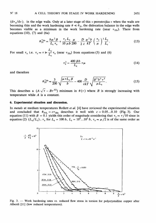
In metals at medium temperatures Rollett et al. [4] have reviewed the experimental situationand concluded that 6IVL = c7IIIs describes it well with c = 0.05...0.10 (Fig. 3). Our
equation (11) with {3 = 0.1 yields this order of magnitude considering that Tc = R/10 since inequation (2) (Lei Lc) . Te for Le =100 b, Lc =104...105 b, Te = IL /2 is of the same order as
Fig. 3. - Work hardening rates vs. reduced flow stress in torsion for polycrystalline copper afterAlberdi [11] (low reduced temperatures).

2452
Te. Note that OIVL does not further increase with T - it is constant (also with respect toë) - at least in single-phase materials. Only the value of 6IVL at the starting stress
TIIIs of stage IV increases. with this stress, the reason being that the wall strength is thenconstant but the cell size is inversely proportional to rjjl,. In the high temperature case ofcopper and the semiconductors (Figs. 4, 5) the relation of the increasing section ofthe 0(T) curve near the minimum is indeed a parabolic one with 6IVH =10 (Nl/2/mm) T
112 compatible with equation (15) with Le =100 b. An analysis also of the
temperature dependent tail for Ge of 0 (T ) in stage III in terms of equation (15) is given byHaasen et al. [24]. The work hardening rate 0 IVH for copper measured by Anon ba et al. [8] isplotted according to equation (15) in figure 6. The slope is, as for Ge, 9 MPa, but there isan intercept of the 0 (,,7-r-) line of the order of the CRSS of copper at these temperatures. Fccmetals or semiconductors are considered here not because of a particular binding but theyrepresent well studied classes of crystals of different reduced stacking fault energy
Fig. 4. - Work hardening rate of silicon single crystals for various temperatures after Siethoff et al.
Fig. 5. - Work hardening curves of copper single crystals at high temperatures after Anongba et al. [8].

2453
Fig. 6. - Stage IV work hardening rates of figure 5 vs. square root of flow stress.
(Ylgb). If this quantity is large then cross slip is easy and vc. vs. This and the reduced
temperature (T/Tm) are responsible for the preference of a particular dynamical recoverymechanism, cross slip or climb, in stage III. The other one then follows in’ stage V (notconsidered here). That there is a rehardening stage in-between them has to do with theincreasing strength of the cell walls in our model. It does not describe so far how precisely acell structure forms out of the less structured dislocation arrangement governing stage II. Bccmetals with their relatively easy cross slip should behave like fcc, at low T
References
[1] PRINZ F. and ARGON A. S., Acta Met. 32 (1984) 1021.[2] NIX W. D., GIBELING J. C. and HUGHES D. A., Met. Trans. 16A (1985) 2215.[3] BRION H. G., and HAASEN P., Philos. Mag. A 51 (1985) 879.[4] ROLLETT A. D., KOCKS U. F. and DOHERTY R. H., Los Alamos Natl. Lab. Report (1987) p. 211.[5] ROLLETT A. D., KOCKS U. F., EMBURY J. D., STOUT M. G. and DOHERTY R. D. (Pergamon,
Oxford) Proc. ICSMA 8 (1988) 433.[6] HAASEN P., Cz. Jl. Phys. B 28 (1988) 494.[7] HAASEN P. (Pergamon, Oxford) Proc. ICSMA 8 (1988) 343.[8] ANONGBA P., BONNEVILLE J. and MARTIN J. L. (Pergamon, Oxford) Proc. ICSMA 8 (1988) 265.[9] ZEHETBAUER M., SEUMER U. and WITZEL W. (Pergamon, Oxford) Proc. ICSMA 8 (1988) 451.
[10] SIETHOFF H. and SCHRÖTER W., Z. Metallkunde 75 (1984) 475, 482.[11] ALBERDI G., Thesis, Univ. of Navarra (1984).[12] HUGHES D. A., Thesis, Stanford Univ. (1986).[13] ROLLETT A. D., Thesis, Drexel Univ. (1988).[14] MECKING H. and GRINBERG G. (Pergamon, Oxford) Proc. ICSMA 5 (1979) 289.[15] PFAFF F., Z. Metallkunde 53 (1962) 411, 466.[16] KOCKS U.-F., Philos. Mag. 11 (1966) 541.[17] KUHLMANN-WILSDORF D., Met. Trans. 224 (1962) 1047.[18] MUGHRABI H., Mat. Sci. Eng. 85 (1987) 15.[19] ESSMANN U. and DIFFERT H., Scr. Met. (1989) in press.[20] ESSMANN U. and MUGHRABI H., Philos. Mag. A 40 (1979) 735.[21] NIX W. D. (1988) unpublished.[22] SEEGER A. (Springer, Berlin) Handb. Physik VII 2 (1955).[23] ESCAIG B. and BONNEVILLE J., Acta Met. 27 (1979) 1477.[24] HAASEN P., ALBORN K. and SCHRÖTER W., Isv Akad. Nauk. 51 (1987) 749.