influence of hardening on the microstructure and the wear ... · influence of hardening on the...
TRANSCRIPT
Science of Sintering, 42 (2010) 183-191 ________________________________________________________________________
_____________________________
*) Corresponding author: [email protected]
doi: 10.2298/SOS1002183P UDK 622.785:669.15-196
Influence of Hardening on the Microstructure and the Wear Capacity of Gears Made of Fe1.5Cr0.2Mo Sintered Steel
W. Predki, A. Miltenović*)
Department LMGK on the Ruhr-University Bochum, Germany Abstract:
High demands are set on gears made from sintered steel regarding wear, fretting, tooth fracture and pitting load capacity. The hardening obtained after the sinter process will affect the microstructure of the sintered steel so that the wear load capacity can increase to higher values. This report shows the influence of different hardenings methods on crossed helical gears fabricated from Fe1.5Cr0.2Mo sintered steel and the changes induced on the microstructure, the surface and the core hardness and the wear load capacity. The research presented in this paper is aimed at finding the most appropriate additional treatment which leads to higher wear load capacity as compared to the wear of sintered steel gears without any additional treatment. Key words: Sintered steel, Gears, Transmission, Wear
1. Introduction
Sintering is a method established for making metal objects from powders and every single step of this process is having an influence on certain material property. The parts made by powder metals are the main group of products in powder metallurgy. They are very profitable products in a highly developed industry, being used in the automotive industry, machinery as well as in many other areas of the metalworking industry. Compared with other types of production, the marked share of sintered parts is not so big but it shows a constant steady growth. Over the time, the sintered parts have developed from unimportant parts to the very important functional parts like the one which is investigated here. These parts must always transfer high static loads but often dynamic loads also. A review of conventional procedures for manufacturing parts using the sintering process can be found, for example, in [1]. The base material for the sintered steel is iron powder in its elementary form. To obtain the corresponding features, by using special techniques, different metal powders are mixed with the pure iron powder.
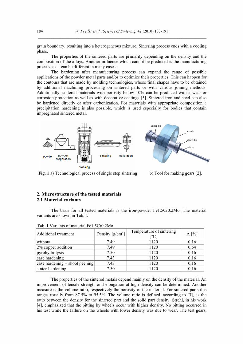
The pressing process requires a precise amount of powder to be dosed into the tool (Fig. 1) which will subsequently be compressed until the reduction of the volume by a factor between 2 and 2.5 is achieved. The pressure applied by the punch determines the final density of material; for example, a density of 7.5 g/cm3 can be obtained by applying 800 N/mm2.
The raw parts obtained by pressing are further subjected to a step thermal process in the flow furnace (heating, sintering, cooling). For parts with direct hardening, the sintering process is usually performed at a temperature of 1120 oC in an atmosphere of reducing gases. In this way, new crystals are formed during sintering due to the diffusion processes at the
W. Predki et al. /Science of Sintering, 42 (2010) 183-191 ___________________________________________________________________________
184
grain boundary, resulting into a heterogeneous mixture. Sintering process ends with a cooling phase.
The properties of the sintered parts are primarily depending on the density and the composition of the alloys. Another influence which cannot be predicted is the manufacturing process, as it can be different in many cases.
The hardening after manufacturing process can expand the range of possible applications of the powder metal parts and/or to optimize their properties. This can happen for the contours that are made by molding technologies, whose final shapes have to be obtained by additional machining processing on sintered parts or with various joining methods. Additionally, sintered materials with porosity below 10% can be produced with a wear or corrosion protection as well as with decorative coatings [5]. Sintered iron and steel can also be hardened directly or after carbonization. For materials with appropriate composition a precipitation hardening is also possible, which is used especially for bodies that contain impregnated sintered metal.
Fig. 1 a) Technological process of single step sintering b) Tool for making gears [2].
2. Microstructure of the tested materials 2.1 Material variants
The basis for all tested materials is the iron-powder Fe1.5Cr0.2Mo. The material variants are shown in Tab. I.
Tab. I Variants of material Fe1.5Cr0.2Mo
Additional treatment Density [g/cm³] Temperature of sintering [°C] A [%]
without 7.49 1120 0,16 2% copper addition 7.49 1120 0,64 pyrohydrolysis 7.50 1120 0,16 case hardening 7.43 1120 0,16 case hardening + shoot peening 7.43 1120 0,16 sinter-hardening 7.50 1120 0,16
The properties of the sintered metals depend mainly on the density of the material. An
improvement of tensile strength and elongation at high density can be determined. Another measure is the volume ratio, respectively the porosity of the material. For sintered parts this ranges usually from 87.5% to 95.5%. The volume ratio is defined, according to [3], as the ratio between the density for the sintered part and the solid part density. Strehl, in his work [4], emphasized that the pitting by wheels occur with higher density. No pitting occurred in his test while the failure on the wheels with lower density was due to wear. The test gears,
V. Predki et al./Science of Sintering, 42 (2010) 183-191 ___________________________________________________________________________
185
including additional treatments, used for the experiments were produced by BTMT GmbH in Germany. The powders used in the production process were supplied by Höganäs (Sweden).
2.2 Additional hardening
To increase the wear resistance, the hardness, as well as the tensile strength and elongation are achieved through various methods of hardening of the sintered parts.
Basically sintered steels can also be case hardened. A carburizing of a surface layer is possible when the relative density is at least 85% of theoretical density and the porosity is then less than 15%. While the case hardness depth for steels made by melting metallurgy is mainly influenced by the carburization temperature and time, the porosity is an additional influence for PM parts. The carburization depth for sintered components is therefore highly dependent on the density. Only when the density is higher than 7.3 g/cm³ and the porosity is closed, unique case depth can be achieved with a traditional gas carburizing. Open porosity provides a large surface area because the carburizing agent penetrates into the pores and a diffusion of carbon into the surface of the porous material occurs [5].
In order to improve the mechanical properties, surface compaction methods such as shot peening, deep rolling, laser shock compression as well as different heat treatment processes are used. The purpose of the mentioned procedure is to increase the strength and the wear resistance as well as to achieve a more favorable structure for improved strength carburizing [6].
The pyrohydrolysis treatment of sintered parts based on iron in water vapor is a proven technique to increase the corrosion resistance, hardness and wear resistance. At a reaction temperature of 450°C to 570°C, a thick oxide layer of an approximately 10 μm will form on the surface of the workpiece. Since the iron oxide is formed also into the pores, it will result in the increase of hardness and of tensile strength compared with the untreated condition. However, by increasing the density, the process is not as positive as expected. After the pyrohydrolysis treatment the elongation can be reduced by 50%.
The solubility of copper in iron is temperature dependent. The hereby achievable precipitation hardening (solution annealing, quenching and tempering) causes a significant increase of strength and a higher ductility. An increase of copper content leads to an increase of the tensile strength and to a reduction of the fracture strain. On the other hand, the tensile strength and the fracture strain increase by increasing material density.
The sinter-hardening treatment is a single-stage process in which the thermal treatment is performed directly after the sintering. In order to achieve the desired mechanical properties it is possible to change the microstructure and the amount of the formed martensite structure by controlling the cooling rate after the sintering process. It is possible to form more martensite structure by using right alloyed materials. This increase significantly the hardness and improve mechanical properties.
The advantages of sinter-hardening treatment: cost savings obtained when the additional cost of alloying is less than the other treatment costs; high dimensional accuracy; good shape retention - compared with other hardening treatments shape of parts would have only minimal deformation during the sintering process; no defects – cracks do not occur during sinter-hardening treatment because parts are not subjected to the drastic rate of temperature change; time saving; readily impregnated – since there is no entrapped quench oil, the gears can be impregnated with lubrication oil; good appearance – gears produced with this hardening process have cleaner and more uniformly colored surfaces.
Gears are typical applications of the sinter-hardening process, for which this kind of treatment leads to improved load capacities [7].

W. Predki et al. /Science of Sintering, 42 (2010) 183-191 ___________________________________________________________________________
186
2.3 Мicrostructure
In order to study the material properties sections into the gears were made. These section pieces were subsequently embedded, grounded and polished. Pictures of this prepared mettalographic specimen were taken with the scanning electron microscope after they were etched in alcoholic nitric acid (2 vol % HNO3).
Fig. 2 The scanning electron micrographs for sample without any tretment
Fig. 3 The scanning electron micrographs for sample with 2% copper addition
The micrograph of the variant without additional treatment (Fig. 2) shows a basic
structure with 70% ferrite and 30% pearlite. Cementite in the pearlite grains loses the lamellar shape and get granular shape, i.e. coagulate. Material should be softer and more durable regarding to the ferritic core structure.
Fig. 4 The scanning electron micrographs for sample with pyrohydrolysis treatment
Fig. 5 The scanning electron micrographs for sample with sinter-hardening treatment
The micrograph of the variant with 2% copper addition (Fig. 3) shows a uniform
ferrite and pearlite microstructure. In grains with pearlite, cementite lamellas are changed into the granular shape.
The increase of the pearlite phase of the granular form is a consequence of the presence of copper. Good mechanical properties are expected due to the uniform distribution of the unconnected pores.
The micrograph picture of the model with the pyrohydrolysis treatment (Fig. 4) shows a uniform, homogeneous fine-grained ferrite and pearlite microstructure. This is a
V. Predki et al./Science of Sintering, 42 (2010) 183-191 ___________________________________________________________________________
187
homogeneous microstructure with enough pearlite phase and with good strength and toughness.
The sinter-hardening process structure leads to a homogeneous microstructure - tempered state with grains in ferritic core microstructure (Fig. 5).
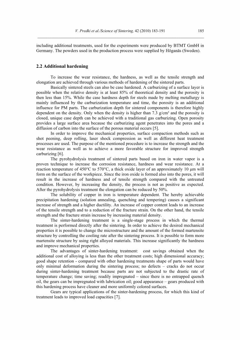
a) Core b) edge area Fig. 6 The scanning electron micrographs for sample with case hardening treatment
Fig. 6a shows the core structure of the tempered martensite, respectively bainite. The Fig. 6b shows the edge area – the hardened layer that has martensitic structure. Altogether, the picture shows a homogeneous microstructure with finely distributed needles.
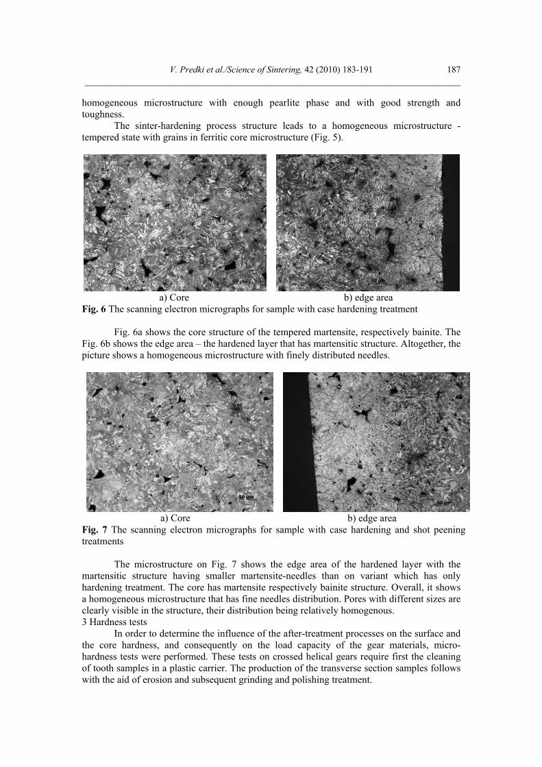
a) Core b) edge area Fig. 7 The scanning electron micrographs for sample with case hardening and shot peening treatments
The microstructure on Fig. 7 shows the edge area of the hardened layer with the martensitic structure having smaller martensite-needles than on variant which has only hardening treatment. The core has martensite respectively bainite structure. Overall, it shows a homogeneous microstructure that has fine needles distribution. Pores with different sizes are clearly visible in the structure, their distribution being relatively homogenous. 3 Hardness tests
In order to determine the influence of the after-treatment processes on the surface and the core hardness, and consequently on the load capacity of the gear materials, micro-hardness tests were performed. These tests on crossed helical gears require first the cleaning of tooth samples in a plastic carrier. The production of the transverse section samples follows with the aid of erosion and subsequent grinding and polishing treatment.
W. Predki et al. /Science of Sintering, 42 (2010) 183-191 ___________________________________________________________________________
188
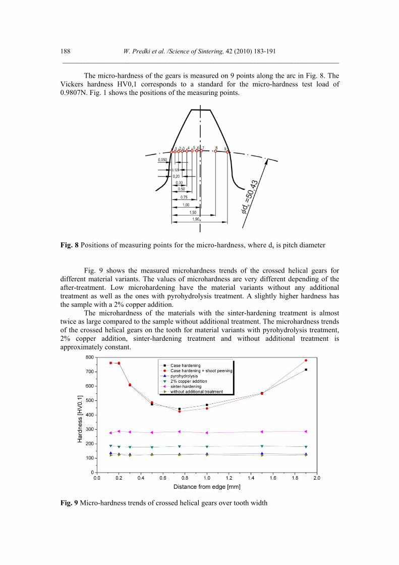
The micro-hardness of the gears is measured on 9 points along the arc in Fig. 8. The Vickers hardness HV0,1 corresponds to a standard for the micro-hardness test load of 0.9807N. Fig. 1 shows the positions of the measuring points.
Fig. 8 Positions of measuring points for the micro-hardness, where ds is pitch diameter
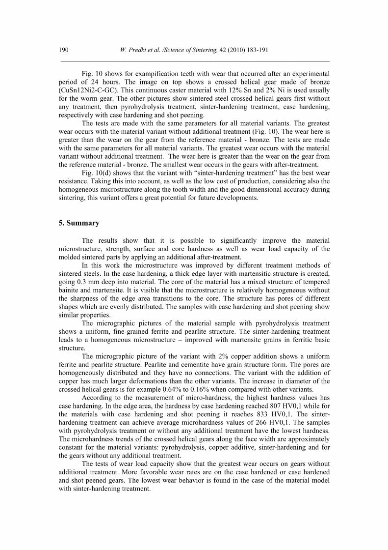
Fig. 9 shows the measured microhardness trends of the crossed helical gears for different material variants. The values of microhardness are very different depending of the after-treatment. Low microhardening have the material variants without any additional treatment as well as the ones with pyrohydrolysis treatment. A slightly higher hardness has the sample with a 2% copper addition.
The microhardness of the materials with the sinter-hardening treatment is almost twice as large compared to the sample without additional treatment. The microhardness trends of the crossed helical gears on the tooth for material variants with pyrohydrolysis treatment, 2% copper addition, sinter-hardening treatment and without additional treatment is approximately constant.
Fig. 9 Micro-hardness trends of crossed helical gears over tooth width

V. Predki et al./Science of Sintering, 42 (2010) 183-191 ___________________________________________________________________________
189
The highest microhardness results are obtained for the materials with case hardening and case hardening followed by shot peening. The microhardness trends of the gears on the tooth width is variable. The largest microhardness is on the edge of the hardened layer with martensitic structure (items 1 and 2).
The microhardness on the edge area of the materials with case hardening is 807 HV0,1. For materials with case hardening and shot peening, the value reached at the edge is 833HV0,1. The core of tooth has smaller hardness and higher toughness. For both variants, the course of the microhardness of the left face width is approximately equal. For sinter-hardening treatment the hardness has an average value of 266 HV0,1.
4. Experimental testing of wear resistance
The worm and the crossed helical gear have a contact in un-wear state at one point. During the experiment, the shape of the tooth flank is change through the wear. Gear data are: a = 30mm, mn = 1,252 (for Fig. 10(a) 1,25), � = 7,507o, z1 = 40, z2 = 1. Experiment is carried out with lubrication (oil) Klüber GH6 1500 (nominal oil viscosity 1500 mm2/s), input speed 5000 min-1, the output torque of 12 Nm and experimental period of 24h.
During the experiment, the shape of the tooth flank is change through the wear on the tooth flank of the crossed helical gear that is changing the shape of the tooth flank.
The worm creates damage on the tooth flank of the crossed helical gear wear surface. Its form is identical to the tooth flank of a worm gear. With advanced wear the wear surface grows, which leads to a lowering of the Hertzian pressures in the tooth contact. In consequence, after some period of work with intensive wear, it comes to a stationary state where the further wear is minimal due to the presence of the oil layer.
Fig. 10 Tooth surface after experiment
W. Predki et al. /Science of Sintering, 42 (2010) 183-191 ___________________________________________________________________________
190
Fig. 10 shows for exampification teeth with wear that occurred after an experimental period of 24 hours. The image on top shows a crossed helical gear made of bronze (CuSn12Ni2-C-GC). This continuous caster material with 12% Sn and 2% Ni is used usually for the worm gear. The other pictures show sintered steel crossed helical gears first without any treatment, then pyrohydrolysis treatment, sinter-hardening treatment, case hardening, respectively with case hardening and shot peening.
The tests are made with the same parameters for all material variants. The greatest wear occurs with the material variant without additional treatment (Fig. 10). The wear here is greater than the wear on the gear from the reference material - bronze. The tests are made with the same parameters for all material variants. The greatest wear occurs with the material variant without additional treatment. The wear here is greater than the wear on the gear from the reference material - bronze. The smallest wear occurs in the gears with after-treatment.
Fig. 10(d) shows that the variant with “sinter-hardening treatment” has the best wear resistance. Taking this into account, as well as the low cost of production, considering also the homogeneous microstructure along the tooth width and the good dimensional accuracy during sintering, this variant offers a great potential for future developments. 5. Summary
The results show that it is possible to significantly improve the material microstructure, strength, surface and core hardness as well as wear load capacity of the molded sintered parts by applying an additional after-treatment.
In this work the microstructure was improved by different treatment methods of sintered steels. In the case hardening, a thick edge layer with martensitic structure is created, going 0.3 mm deep into material. The core of the material has a mixed structure of tempered bainite and martensite. It is visible that the microstructure is relatively homogeneous without the sharpness of the edge area transitions to the core. The structure has pores of different shapes which are evenly distributed. The samples with case hardening and shot peening show similar properties.
The micrographic pictures of the material sample with pyrohydrolysis treatment shows a uniform, fine-grained ferrite and pearlite structure. The sinter-hardening treatment leads to a homogeneous microstructure – improved with martensite grains in ferritic basic structure.
The micrographic picture of the variant with 2% copper addition shows a uniform ferrite and pearlite structure. Pearlite and cementite have grain structure form. The pores are homogeneously distributed and they have no connections. The variant with the addition of copper has much larger deformations than the other variants. The increase in diameter of the crossed helical gears is for example 0.64% to 0.16% when compared with other variants.
According to the measurement of micro-hardness, the highest hardness values has case hardening. In the edge area, the hardness by case hardening reached 807 HV0,1 while for the materials with case hardening and shot peening it reaches 833 HV0,1. The sinter-hardening treatment can achieve average microhardness values of 266 HV0,1. The samples with pyrohydrolysis treatment or without any additional treatment have the lowest hardness. The microhardness trends of the crossed helical gears along the face width are approximately constant for the material variants: pyrohydrolysis, copper additive, sinter-hardening and for the gears without any additional treatment.
The tests of wear load capacity show that the greatest wear occurs on gears without additional treatment. More favorable wear rates are on the case hardened or case hardened and shot peened gears. The lowest wear behavior is found in the case of the material model with sinter-hardening treatment.
V. Predki et al./Science of Sintering, 42 (2010) 183-191 ___________________________________________________________________________
191
6 References
1. G. Kotthoff: Neu Verfahren zur Tragfähigkeitssteigerung von gesinterten Zahnrädern. Aachen, 2003 (in German)
2. T. Wendt: Tragfähigkeit von Schraubradgetrieben mit Schraubrädern aus Sintermetall, Bochum, 2008. (in German)
3. DIN 30900: Terminologie der Pulvermetallurgie; Einteilung; Begriffe, 7/1982. 4. R. Strehl: Tragfähigkeit von Zahnrädern aus hochfesten Sinterstählen, Aachen, 1997.
(in German) 5. S. Seyedi: Schwingfestigkeit einsatzgehärteter Sinterstähle. Karlsruhe (TH), 2006. (in
German) 6. U. Engstrom, A. Klekovkin, S. Berg, B. Edwards, L. Frayman, G. Hinzmann, D.
Whitehouse in “Advances in Powder Metallurgy and Particulate Materials”, MPIF, Princeton, NJ 2005.
7. A. Miltenović, Journal of Mechanical Engineering Design. Vol.8. N°2. January, 2005. p. 33-40.
Садржај: Од синтер материјала за израду зупчаника захтева се висока носивост у односу на хабање, зарибавање, лом зупца у подножју и у односу на питинг. После израде делова синтеровањем, одговарајућом завршном термичком обрадом могуће је утицати на структуру синтер челика, тако да се добија висока отпорност у односу на хабање. У раду су приказани резултати истраживања утицаја различитих поступака завршне обраде зупчаника завојних преносника од Fe1,5Cr0,2Mo синтер челика на структуру, површинску тврдоћу и тврдоћу језгра, као и отпорност у односу на хабање. Циљ рада је дакле налажење поступка завршне термичке обраде, ради добијања високе носивости у односу на хабање зупчаника од синтер челика. Кључне речи: синтеровани челик, зупчаник, преносник, хабање