988726umpb - user manual - admiral 26 rev a...
TRANSCRIPT

User Manual
Admiral 26

2
PrefaceDear customer, Thank you for purchas-ing the PowerBoss® Admiral 26. The outstanding operational characteristics of the Admiral 26 should justify the con-fidence you demonstrated in making this purchase. The Admiral 26 is a commercial grade scrubber machine. It is battery operated and is intended by PowerBoss to be used in accordance with this manual, the labels on the machine itself, as well as applicable federal, state, and local safety and environmental statutes, reg-ulations, and ordinances (collectively the "governmental regulations"), appli-cable commercial standards, and com-mon sense. .The user's own safety, as well as the safety of others, depends to a great ex-tent on how the Admiral 26 is operated, handled, and maintained. Therefore, as a starting point, this manual must be read and understood thoroughly prior to the machine being switched on for the first time. When operating or maintain-ing the Admiral 26, THINK SAFETY FIRST! This manual provides vital information concerning the safe operation, use,
maintenance, and service of the Admi-ral 26. The various safety alert symbols, signal words, and safety messages contained herein are intended to be read in conjunction with each other, as well as with Admiral 26 labels, instruc-tion plates, and applicable governmen-tal regulations. To the extent that any governmental regulations conflict with the provisions of this instruction manu-al, such governmental regulations would govern. Your authorized PowerBoss dealer would be happy to answer any ques-tions you may have concerning the op-eration or maintenance of the Admiral 26 or information contained in this man-ual. If repair or maintenance work is per-formed on the Admiral 26, PowerBoss recommends that only genuine replace-ment parts be used and that such work be performed by qualified individuals.
Proper useThe Admiral 26 is a vacuum scrubbing machine. Its intended scope of applica-tion is for wet cleaning of level, smooth, hard-surfaced floors in accordance with the provisions of this instruction manu-al, applicable governmental regula-tions, manufacturer specifications, and machine labels (collectively, "proper use"). Using the Admiral 26 beyond its proper use will be deemed improper use by PowerBoss. PowerBoss dis-claims any liability for any personal inju-ry, property, or other damages of any nature whatsoever, whether special, in-direct, consequential, or compensatory, directly or indirectly resulting from the improper use of the Admiral 26, or uses beyond or inconsistent with the Admi-ral’s intended scope of application. This disclaimer of liability also extends to modifications to the Admiral 26 made without PowerBoss' prior written con-sent.The Admiral 26 should only be operat-ed, handled, and maintained by per-sons who are familiar with the machine and who have been instructed of the potential hazards associated with such operation, handling, and maintenance.
Introduction

3
Disclaimer: PowerBoss disclaims liability for any personal injury, property, or other dam-ages of any nature whatsoever, wheth-er special, indirect, consequential, or compensatory, directly or indirectly re-sulting from the publication, use of, ap-plication, or reliance on this document or, except as expressly set forth in the sales contract for the machine, the op-eration or maintenance of the Admiral 26. EXCEPT AS EXPRESSLY SET FORTH IN SUCH SALES CONTRACT, POWERBOSS MAKES NO WARRAN-TIES, EXPRESS OR IMPLIED, AND SPECIFICALLY DISCLAIMS ANY WARRANTY OF MERCHANTABILITY OR FITNESS FOR A PARTICULAR PURPOSE.PowerBoss disclaims and makes no guaranty or warranty, express or im-plied, as to the accuracy or complete-ness of any information published herein, and disclaims and makes no warranty that the information in this in-struction manual will fulfill any parties' particular purposes or needs. While PowerBoss believes that the informa-tion in this manual is accurate, in the
event that technical or typographical er-rors exist in this manual, PowerBoss re-serves the right to make changes to subsequent editions of this manual without prior notice to the recipients of this edition. The reader should notify PowerBoss if any errors in this manual are suspected. PowerBoss does not undertake to guarantee the perfor-mance of any individual manufacturer or seller's products or services by virtue of this instruction manual.In publishing and making this manual available, PowerBoss is not undertak-ing to render professional or other ser-vices for or on behalf of any person or entity, nor is PowerBoss undertaking to perform any duty owed by any person or entity to someone else. Anyone us-ing this manual should rely on his or her own independent judgment or, as ap-propriate, seek the advise of a compe-tent professional in determining the exercise of reasonable care in any giv-en circumstances.
Valid as of: October 2011
PowerBoss Inc.175 Anderson StreetAberdeen, North Carolina 28315U.S.A.
Introduction

4
Notes on warrantyThe terms of the sales contract apply in regard to any product warranties. Pow-erBoss expressly disclaims all other warranties, either express or implied, of any kind. It should be noted, however, that failure to maintain and service your Admiral 26 in accordance with its prop-er use may void the warranty. In this re-gard, any maintenance work must be performed by an authorized PowerBoss service representative and confirmed in the "Maintenance Certificate" - the war-ranty document. By way of example, the following items are excluded from the Admiral 26 warranty: fuses; normal wear and tear; improper machine han-dling; damages caused by overloads; unauthorized machine modifications; non-compliance with maintenance in-structions or specifications; or improp-erly fitting parts or accessories.
Acceptance of the machineUpon arrival, check machine for possi-ble damages in transit. Follow unpack-ing instructions on shipping pallet. Each unit has been tested and throughly in-spected before shipment. Any damage is the responsibility of the delivery carri-er who should be notified immediately.
PowerBoss Inc.175 Anderson StreetAberdeen, North Carolina 28315U.S.A.
Introduction

5
Table of Contents
Introduction . . . . . . . . . . . . . 2Preface. . . . . . . . . . . . . . . . . . 2Proper use . . . . . . . . . . . . . . . 2Disclaimer . . . . . . . . . . . . . . . 3Notes on warranty . . . . . . . . . 4Acceptance of the machine . . 4
1 Safety Information . . . . . . . . 81.1 Safety and Warning Symbols. 81.2 General Provisions. . . . . . . . . 91.3 Operational Precautions. . . . 101.4 Maintenance Precautions. . . 111.5 Battery and Electrical System
Precautions . . . . . . . . . . . . . 121.6 Cleaning Solution Use and Dis-
posal Precautions. . . . . . . . . 131.7 Machine Labels . . . . . . . . . . 142 Machine Overview . . . . . . . 162.1 Front. . . . . . . . . . . . . . . . . . . 162.2 Rear . . . . . . . . . . . . . . . . . . . 173 Operating Elements . . . . . . 183.1 Operating Panel . . . . . . . . . . 183.2 At the Machine . . . . . . . . . . . 214 First Operation . . . . . . . . . . 264.1 Instruction. . . . . . . . . . . . . . . 264.2 Initial charging procedure. . . 264.3 Before Putting into Operation 264.4 Start Machine . . . . . . . . . . . . 26
4.5 Operation . . . . . . . . . . . . . . . 274.6 Stop Machine . . . . . . . . . . . . 284.7 After Work . . . . . . . . . . . . . . 284.8 Transporting the machine . . 294.9 Tie-down points . . . . . . . . . . 295 Operation . . . . . . . . . . . . . . 305.1 Method of Operation . . . . . . 305.1.1 Brush Deck . . . . . . . . . . . . . 305.1.2 Solution Tank . . . . . . . . . . . . 305.1.3 Squeegee. . . . . . . . . . . . . . . 315.1.4 Recovery Tank. . . . . . . . . . . 315.1.5 Batteries. . . . . . . . . . . . . . . . 315.1.6 Drive motor . . . . . . . . . . . . . 315.1.7 Options. . . . . . . . . . . . . . . . . 316 Technical Data . . . . . . . . . . 327 Maintenance and Care. . . . 347.1 PowerBoss System Mainte-
nance . . . . . . . . . . . . . . . . . . 347.2 Maintenance Document . . . . 357.3 Maintenance Schedule . . . . 367.4 Battery Systems. . . . . . . . . . 407.4.1 Charge Batteries . . . . . . . . . 417.4.2 Charger Specifications. . . . . 417.4.3 Drive Batteries . . . . . . . . . . . 417.4.4 Remove Batteries . . . . . . . . 417.4.5 Install Batteries . . . . . . . . . . 417.4.6 Disposal of Batteries . . . . . . 417.5 Solution tank . . . . . . . . . . . . 42
7.5.1 Fill solution tank . . . . . . . . . . 437.5.2 Empty solution tank . . . . . . . 437.5.3 Solution Filter . . . . . . . . . . . . 437.6 Recovery tank . . . . . . . . . . . 447.6.1 Empty recovery tank . . . . . . 457.6.2 Clean recovery tank . . . . . . . 457.6.3 Clean Suction Filter . . . . . . . 457.7 Disc brush deck . . . . . . . . . . 467.7.1 Clean Brushes . . . . . . . . . . . 467.7.2 Change Brushes . . . . . . . . . 467.7.3 Change Roller Bumper . . . . 467.7.4 Change side squeegee . . . . 467.7.5 Adjust side squeegee. . . . . . 477.8 Cylindrical Brush Deck. . . . . 487.8.1 Clean dirt hopper . . . . . . . . . 487.8.2 Remove brushes . . . . . . . . . 487.8.3 Clean brushes . . . . . . . . . . . 487.8.4 Replace brushes . . . . . . . . . 487.8.5 Change roller bumper . . . . . 487.8.6 Adjust side squeegee. . . . . . 497.9 Squeegee. . . . . . . . . . . . . . . 507.9.1 Cleaning the Squeegee . . . . 507.9.2 Change Squeegee Blades . . 507.9.3 Adjusting the Blades . . . . . . 507.9.4 Adjusting lift mechanism . . . 537.10 Machine lubrication . . . . . . . 548 Troubleshooting. . . . . . . . . 56
Warranty. . . . . . . . . . . . . . . . . . . . . 58

6
Safety Information
1 Safety Information
1.1 Safety and Warning SymbolsAll paragraphs in this manual referring to your personal safety, the safety of your machine and the environment pro-tection are attributed one of the follow-ing warning symbols:
Safety Symbols Description
WARNING Indicates a hazardous situation which could result in death or serious injury.
NOTICE Indicates a potentially hazardous situation which may result in equipment or property damage.
Additional Symbols Description
Ecological hazard Indicates the use of substances representing an inherent danger to the health of the environment
Note Indicates important or additional information.

7
Safety Information
1.2 General Provisions• Please read this user manual and in-
struction plates / labels on the Admi-ral 26 unit in their entirety before operation. These materials contain valuable information regarding the safe operation of the machine. Pow-erBoss recommends that operators receive training by qualified Power-Boss technicians before start-up, op-eration, use, servicing, or repair of the machine.
• This user manual is not intended as a substitute for applicable govern-ment regulations; nor does it include or address same. Users, and em-ployers of users, should familiarize themselves with applicable govern-ment regulations that may impact use and operation of the Admiral 26, including, but not limited to, regula-tions promulgated pursuant to the federal Occupational Safety and Health Act.
• The precautions and important safe-ty information contained in this user manual must be made available cur-rent users and downstream users of the machine. When re-selling or renting out Admiral 26 machines, it is
recommended that copies of this user manual be provided and that any illegible machine labels or in-struction plates be replaced.
• The Admiral 26 is designed for in-door use only. Store machine in-doors. Keep the electrical components of the machine dry.
• Make sure that all warning labels and instruction plate on the machine are maintained, legible, and properly attached.

8
Safety Information
1.3 Operational PrecautionsThe Admiral 26 is a battery-operated hard surface floor cleaning system that utilizes a water / cleaning solu-tion that is applied to the floor and then vacuumed back into the ma-chine by way of an integrated squee-gee for later disposal.
Liquid residue remaining on the floor during operation can rep-resent a slip and fall hazard to the operator and others in the vicinity of machine use. When working with the machine, op-erators should use firm and skid-proof shoes. Areas where floor cleaning will occur should be appropriately marked with suitable slip and fall hazard signs / markers / pop-up cones, etc!
• It is indispensable for the operator or user of the machine to become thor-oughly acquainted with attached im-plements and controls - as well as their various functions - before oper-ation commences.
• Before commencing operation of the machine, check for obvious signs of loose parts, potential conditions in-
dicative of malfunctions, etc. Any signs of potential problems must be remedied before actual operation commences.
The electrical system in the machine is not designed to suppress sparks. Accordingly, use of the Admiral 26 where fire or explosion hazards may exist due to flammable gases or vapors, flammable liquids, combustible dust, or ignitable fibers or flyings, must be avoid-ed. The machine can cause an explosion when operated near such areas.
Use caution when operating the machine on a ramp or in-cline. Do not turn the machine on an incline, as it may be-come unstable and flip over. Do not leave the machine unat-tended on a ramp or incline, as it could roll freely and result in personal injury. The Admiral 26 is not designed for use on sur-faces with a greater than 6% incline or slope. Adopt opera-tion habits to local conditions to
ensure machine is always un-der operator's control.The Admiral 26 is not designed for decontamination purposes and should not be used in ar-eas where hazardous wastes or materials are stored or have been spilled. Use of the Admi-ral 26 in these areas could re-sult in the spread of hazardous wastes or materials and opera-tor exposure to same.
• Remove the key to avoid unautho-rized use of the machine.

9
Safety Information
1.4 Maintenance Precautions• Maintenance and repairs must be
performed by qualified personnel only. Maintain adjustments on ma-chine pursuant to specifications not-ed in the service manual.
• Maintenance and repair work must be performed by using appropriate, undamaged tools.
• Spare and replacement parts must conform with factory machine speci-fications. Failure to do so may result in machine malfunctions. Genuine spare and replacement parts are highly recommended.
Switch off and remove the ma-chine's key before inspecting the machine or performing any maintenance or repair work. Failure to do so may result in accidental machine activation and personal injury.When performing maintenance or repair work on the ma-chine's electrical system, be sure to disconnect the ma-chine's battery plug first. Fail-ure to do so could result in ac-cidental machine activation and personal injury.
• Before commencing operation of the machine, check for obvious signs of loose parts, potential conditions in-dicative of malfunctions, etc. Any signs of potential problems must be remedied before actual operation commences.
Before commencing operation of the machine following main-tenance or repair activities, check to ensure that all protec-tive devices have been proper-ly refitted and positioned, or other potential problems be-fore actual operation com-mences, otherwise personal injury may occur.

10
Safety Information
1.5 Battery and Electrical Sys-tem PrecautionsThe Admiral 26 operates on ei-ther lead acid or AGM batter-ies. Batteries can generate gases which can ignite or cause an explosion. Keep sparks and flames away from the batteries. Charge the bat-teries only in well ventilated ar-eas. Wear eye protection when working near batteries. Do not put any type of metal objects or tools across the battery termi-nals or on top of batteries. Do not clean the machine's electri-cal parts or system, including batteries, by means of high-pressure cleaning equipment. Such activities could cause short-circuit or battery explo-sion hazards, resulting in per-sonal injury.
• Only use a charger designed for your specific battery type.
• Only qualified individuals should at-tempt to undertake maintenance and repair activities associated with the machine's electrical system in accor-
dance with appropriate industry standards and government regula-tions, if any.
• The electrical system of the machine should be inspected at regular inter-vals. Any obvious defects, such as loose connections, damaged or frayed electrical cables, corrosion, should be repaired before the ma-chine is put back into use. Failure to do so could cause machine malfunc-tions or electrical hazards.
• In case of a malfunction of the ma-chine's electrical system, including, but not limited to, unexpected loss of power or individual system shut-downs, the machine should be shut down immediately for inspection and required maintenance and repair.
Batteries must be selected and seated appropriately in accor-dance with factory machine specifications. Failure to do so could result in inappropriate changes to the machine's cen-ter of gravity which, in turn, could result in machine opera-tion and control hazards (espe-cially on inclined surfaces) and related personal injury.
• Observe all operating, use, and safe-ty instructions provided by the appro-priate battery manufacturer.
Used batteries must be han-dled, disposed, or recycled properly in accordance with government regulations. Used batteries should never be dis-posed of as non-hazardous waste (e.g. domestic or house-hold waste). Used batteries should be disposed or recycled by appropriately trained and permitted entities and /or dis-posal facilities.

11
Safety Information
1.6 Cleaning Solution Use and Disposal Precautions
• Only cleaning agents / detergents suitable for automatic machines (low foaming) should be used in the Ad-miral 26. Cleaning agents / deter-gents should be mixed with water in ratios established by product labels and or manufacturer recommenda-tions. All safety precautions estab-lished by the cleaning agent / detergent's manufacturer (including, but not limited to, use of gloves and safety glasses) must be followed. These safety precautions can typi-cally be found on the cleaning agent / detergent's product labels, accom-panying collateral materials, and re-lated Material Safety Data Sheets
• Used or spent mixtures of water and cleaning agents / detergents collect-ed in the machine's recovery tank must be disposed of in accordance with applicable government regula-tions and or local permits obtained by the facility in which floor cleaning activities occur, if any. Violations of such government regulations and lo-cal permits can result in significant penalties.
Never dispose of the contents of the machine's recovery tank outdoors or into stormwater systems or basins!

12
Safety Information
1.7 Machine LabelsThe following safety and information la-bels are legibly attached to the ma-chine. Replace missing or illegible labels immediately.
PowerBoss nameplate (Fig. 1/1)
Recovery tank drain hose (Fig. 2/1)
Battery cable routing (Fig. 1/2)
Water temp warning (Fig. 1/4)
Off aisle wand switch (Fig. 2/2)
Battery caution (Fig. 1/5)

13
Safety Information
General information (Fig. 1/3)
A = Read and observe the instruction manual B = Maximum inclination of 6%C = Do not clean the machine by meansof high-pressure cleaning equipment
Fig.1 Fig.2
A
B
C
1 3
2
4
5 1
2

14
Machine Overview
2 Machine Overview
2.1 Machine Overview - Front1 Recovery tank lid2 Steering wheel3 Drive wheel4 Roller bumper5 Foot step6 Side squeegee7 Scrub deck8 Solution level sight gauge9 Seat adjustment lever10 Solution tank11 Solution tank fill port12 Hourmeter13 Circuit breakers
Fig.3
2
35
1
10
11
4
67
8
9
1213

15
Machine Overview
2.2 Machine Overview - Rear14 Recovery tank dump hose15 Off aisle wand hose connection16 Suction hose17 Clean-out18 Rear squeegee19 Recovery tank20 Safety latch21 Accelerator pedal22 Control panel23 Rear Wheel24 Solution tank drain hose25 Off aisle wand switch
Fig.4
14
18
22
15
17
19
20
1621
23
24
25

16
Operating and Indicating Elements
3 Operating and Indicat-ing Elements
3.1 Operating Panel1 Direction selector2 LED indicator - Forward3 Battery / Fault gauge4 Solution control5 Horn6 Key switch7 LED indicator - Reverse8 Double scrub mode9 Regular scrub mode10 Heavy scrub mode11 Mode selector12 Vacuum only mode13 Transport mode
Fig.5
1 2
5 6 7
3 4
8 9 10 11 1312

17
Operating and Indicating Elements
Direction selector (Fig. 5/1)Controls the direction in which the Ad-miral 26 will move when the accelerator pedal is activated. The arrow pointing forward the amber LED (Fig. 5/2) indi-cates the machine is in forward mode. The arrow pointing backward with the red LED (Fig. 5/7) indicates the ma-chine is in reverse mode.
Battery / Fault gauge(Fig. 5/3)This gauge displays the remaining bat-tery charge. This gauge also displays any fault codes that might occur with the machine controller (see “Trouble-shooting” for fault codes).
Solution control(Fig. 5/4)This control will adjust the amount of solution that is dispersed to the floor while in one of the scrub modes. Adjust control clockwise to increase the amount of solution being dispersed. The solution flow range is from zero (0) to a maximum of ¾ GPM.
Horn (Fig. 5/5)Activates the electric horn.
Key Switch(Fig. 5/6)The key switch turns the electrical sys-tem on and off.
Remove the key to avoid unau-thorized use of the machine.
Mode selector(Fig. 5/11)Selects the operating mode of the ma-chine.
Regular scrub mode(Fig. 5/9)This mode is recommended for day-to-day tasks under normal conditions. With the direction selector in the for-ward position and the accelerator pedal is activated, the solution pump will turn on, brushes will turn on and lower, vac-uum motor will turn on and squeegee will lower. When the accelerator pedal is released and the machine stops mov-ing, the scrub deck will automatically raise and turn off the brushes, the squeegee will raise and the vacuum motor will turn off after a delay. If the di-rection selector is in the reverse posi-tion, the machine will operate the same as in forward mode, only the squeegee will raise up.

18
Operating and Indicating Elements
Heavy scrub mode(Fig. 5/10)This mode is recommended for high traffic areas and areas that have been heavily soiled. The machine will operate the same as if it was in Regular Scrub Mode, only in this mode brush pressure is increased.
Double scrub mode(Fig. 5/8)This mode is recommended if the floor is heavily soiled and the cleaning chem-icals will need additional time to emulsi-fy grease and oils that are on the floor. With the direction selector in either the forward or reverse position and the ac-celerator is activated, the solution pump will turn on, the brushes will turn on and lower to the floor. The rear squeegee will not lower. This allows the chemical solution time to remain on the floor. Af-ter double scrubbing, vacuum only mode should be used to recover the dirty solution water from the floor.
Vacuum only mode(Fig. 5/12)This mode is recommended for solution removal after double scrubbing, but can also be used to pick up spills. When the accelerator pedal is activated with the direction selector in the forward posi-tion, the rear squeegee will lower to the floor as the vacuum motor turns on pull-ing the dirty solution water from the rear squeegee into the recovery tank. If the machine stops moving and the direction selector is switched to reverse, the rear squeegee will raise (protecting it from damage) and the vacuum motor will turn off after a delay. If the machine stops moving in either direction, the squeegee will automatically raise and the vacuum motor will shut off after a delay.
Transport mode(Fig. 5/13)When this mode is selected, none of the cleaning functions will operate. This mode is only used to transport the ma-chine from one location to another.

19
Operating and Indicating Elements
3.2 At the Machine
1 Seat adjustment lever2 Solution tank fill port3 Solution filter4 Solution drain hose5 Solution level sight gauge6 Recovery drain hose7 Recovery tank lid8 Suction filter9 Off aisle wand switch
Fig.6
1
2
3
4
5
8
96
7

20
Operating and Indicating Elements
Seat adjustment lever (Fig. 6/1)Use this lever to adjust the seat forward or backward.
Solution tank fill port (Fig. 6/2)The solution tank is filled through this port.
Solution filter (Fig. 6/3)While solution flows from tank to brush deck, it is cleaned by the filter element.
Solution tank drain hose (Fig. 6/4)This hose allows draining of the solution tank.
Solution level sight gauge (Fig. 6/5)The amount of solution in the tank can be checked visually using this gauge.
Recovery tank drain hose (Fig. 6/6)This hose allows draining of the collect-ed soiled water from the tank.
Recovery tank lid (Fig. 6/7)Removing this lid allows access to the recovery tank and suction filter.
Suction filter (Fig. 6/8)This filter protects the vacuum motor from water and debris.
Off aisle wand switch (optional) (Fig. 6/8)This switch activates the optional off aisle wand.
Hourmeter (Fig. 3/12)The hourmeter displays the current op-erating hour level.
1 1 1 1

21
Operating and Indicating Elements
Dirt hopper guiding rail (Fig. 7/1)The dirt hopper located at the cylindrical brush deck is fastened by a guiding rail. This dirt hopper may be easily removed for cleaning.
Cylindrical brush hub (Fig. 7/2)This hub (both sides) can be removed to access the cylindrical brushes. The cylindrical brushes may be easily re-moved without tools.
Side squeegee pivot (Fig. 7/3)Pivot the side squeegee in lifted posi-tion to allow access to the cylindrical brush hub without disturbing the align-ment of the side squeegees. This can be done without tools by removing the yellow star shaped knob.
Dirt Hopper (Fig. 7/4)Floor debris is swept into the dirt hop-per.
Fig.7 1 Dirt hopper guiding rail2 Cylindrical brush hub3 Side squeegee pivot bracket4 Dirt hopper
2
3
1
4

22
Operating and Indicating Elements
Disc deck cover(Fig. 8/1)This cover (both sides) can be removed to access the disc brushes. The deck cover can be easily removed without tools.
Disc brush (Fig. 8/2)The disc brushes can be easily re-moved without the use of tools using down force to dislodge the brush.
Fig.8 1 Disc deck cover2 Disc brush
1
2

23
Operating and Indicating Elements
Off aisle wand tool (Optional)The Admiral 26 is equipped with a ready-to-use built-in telescoping off-aisle wand system for use in hard to reach areas. By activating the pump switch (Fig. 6/9) the wand is ready to use.
Solution trigger (Fig. 9/1)The trigger controls the solution flow to the spray jet. Squeezing the trigger opens an internal valve to dispense cleaning solution.
Telescoping wand (Fig. 9/2)The telescoping wand allows the length to be adjusted for operator comfort or storage.
Wand extender (Fig. 9/3)Sliding the extender forward (as shown) extends the wand during use and re-tracts by pulling it back for the storage position.
Flip-flop tool (Fig. 9/4)can be changed from scrub brush (Fig. 7/6) to vacuum squeegee (Fig. 7/5) by simply rotating the end.
Fig.91 Solution trigger2 Telescoping wand3 Wand extender4 Flip-flop tool5 Vacuum squeegee6 Scrub brush
1
5
6
2 3
4
24
First Operation
4 First Operation
4.1 InstructionOnly persons trained by qualified Pow-erBoss technicians are authorized to operate, service and repair the ma-chine. Operators must read and under-stand this manual before operating or maintaining this machine.
4.2 Initial charging procedure
Be sure to use proper charger per battery type.
Before first operation of the machine, fully charge the bat-tery with an initial charging pro-cedure and comply with the op-erating instructions of the charger as well as with those of the battery manufacturer. Pow-erBoss cannot be held liable for damages resulting from an insufficient initial charge.
4.3 Before Putting into OperationComplete the following inspections be-fore taking the machine into operation:1. Check the area around the machine
for signs of leakage. Hoses, lines
and tanks must be free from any leakage or damage.
2. Install brushes and squeegee, see maintenance chapter.
3. Install batteries and connect battery plug, see maintenance chapter.
4. Check battery charge and recharge if required. An initial charge is re-quired before first operation of the machine. (see Maintenance section)
5. Empty recovery tank and clean it if required, see maintenance chapter.
6. Refill solution tank and add cleaning agent according to the manufactur-er's recommendations.
Use only cleaning agents suit-able for automatic machines (low-foaming) and comply with the instructions for use, dispos-al and with the warning infor-mation specified by the clean-ing agent's manufacturer.
4.4 Start MachineProceed with the following to set the machine to operating mode:• Disconnect the charger and connect
the battery connector• Switch on machine by actuation of
key switch from position (0) to posi-tion (1). The battery gauge will dis-play the remaining battery life.
25
First Operation
4.5 Operation1. Switch on the machine.2. Select one of the five available
modes using the mode selector (Fig. 5/11).
3. Set the direction the machine will travel by selecting forward or reverse on the direction selector (Fig. 5/1).
4. Activating the accelerator pedal (Fig. 4/19) turns on the transport, brush-es, water flow, vacuum, and lowers the rear squeegee accordingly to the mode selected.
If the accelerator pedal is acti-vated before, or the key is switched “ON” at the same time, the machine will not move as a safety precaution. Remove your foot from the pedal, turn the machine OFF and ON, then activate the ped-al to drive the machine.
When the direction switch is set to reverse and the acceler-ator is activated, the back up alarm will sound and the rear squeegee will automatically raise. However, the scrub brushes will continue to rotate and solution will continue to flow.
5. Start scrubbing by driving the ma-chine forward in a straight line at 3/4 speed overlapping each path by 2 to 3 inches.
Start moving machine immedi-ately after switching on the brush deck, otherwise the brushes leave traces on the floor. Lift brush deck before passing over steps and other obstacles.
6. When scrubbing, check behind the machine occasionally to see that all of the dirty water is being picked up.
If streaking occurs, the recov-ery tank may be full, the suc-tion hose may be clogged, de-bris may need to be removed from the squeegee, or the rear squeegee may require adjust-ment. (Refer to “Maintenance” section before making any ad-justments.)
In cases where the floors are extremely soiled or dirty, the double scrub mode may be needed. (Refer to “Operating and Indicating Elements” sec-tion.)
The recovery tank has a safe-guard for overflow protection to guard against water entering the vacuum motor when the re-covery tank is full. The Vacuum will stay ON for 15 seconds and then shut-off automatical-ly. When this happens, imme-diately empty the recovery tank.
7. Drive the machine to a designated dirty water disposal area and empty

26
First Operation
the recovery tank. (Refer to “Mainte-nance” section for instructions.)
8. Refill the solution tank and continue scrubbing until the job is done or the machine runs out of charge.
The battery/ fault gauge (Fig. 5/3) will flash to signal that the machine is almost out of pow-er. When this signal is dis-played, all functions will shut off (brushes will turn off, the scrub deck and squeegee will raise. The key switch must be turned OFF then ON to reset the machine. The machine will then only have a few minutes left of reserve power for a short vacuum only mode to pick up remaining solution on the floor and transport power to drive to the battery recharging station. If the machine is operated for an excessive period of time af-ter cleaning functions have stopped, it will eventually turn itself off. The machine will have to be pushed back to the re-charging station.
4.6 Stop MachineTo stop scrubbing, select the transport mode (Fig. 5/13). This will automatically stop the solution flow, raise the scrub-deck, raise the squeegee, and turn off the vacuum motor (15-second delay).
4.7 After WorkRefer to the “Maintenance” section for specific maintenance instructions de-scribed below.1. When finished scrubbing, select the
transport mode (Fig. 5/13), all clean-ing functions will shut off. Move the machine to a suitable site for mainte-nance.
2. Empty and clean the solution tank 3. Empty and clean the recovery tank
Observe the legal directives and local regulations for dis-posal of detergents.
4. Remove and clean the brushes or pad holders.
5. Remove and clean the rear squee-gee
6. Check operating fluid levels, function and setting.
7. Remove and clean the side squee-gees.
8. Clean the machine.
Do not clean the electrical parts by means of high-pres-sure cleaning equipment.
9. Check the maintenance schedule and perform any required mainte-nance before storing the machine.
10.Charge batteries.11.Store the machine indoors in a clean
dry place.
Keep from freezing
Leave the solution and recov-ery tank lids open for ventila-tion to prevent odor build-up.
12.Turn key switch OFF and remove key.
Remove the key to avoid unau-thorized use of the machine.

27
First Operation
4.8 Transporting the machineTo transport the machine, turn the key switch ON, select the transport mode, select forward or reverse, activate the accelerator pedal to start movement.
4.9 Tie-down pointsWhen transporting on a vehicle or trail-er, the machine has to be secured. Tie the machine down firmly by using the front foot steps (Fig. 10/1) and the rear tie hooks (Fig. 10/2) as tie-down points.
Fig.10
1 2

28
Operation
5 Operation5.1 Method of OperationGeneralThe Admiral 26 is a vacuum scrubbing machine for wet cleaning of hard-sur-faced floors.
5.1.1 Brush DeckBrush deck (Fig. 11/1) automatically lowers when traveling with a cleaning mode selected. The brushes rotate and solution supply switches on automati-cally. When the machine stops, brushes and solution supply switch off automati-cally.
5.1.2 Solution TankFill the solution tank (Fig. 11/2) through solution fill port (Fig. 11/5). The solution tank holds 27 gallons and the filling lev-el can be checked visually through the solution level sight gauge (Fig. 11/6).
Fig.11
6
7
1
2
5
3
4
8

29
Operation
5.1.3 SqueegeeThe rear squeegee system (Fig. 11/3) consists of squeegee blades, vacuum motor, and suction hose. The soiled wa-ter is wiped from the floor by means of squeegee blades. Squeegee lowers au-tomatically when corresponding clean-ing mode is selected. Simultaneously, the vacuum motor switches on. The vacuum motor works independent of di-rection of travel and even if the machine stops. Changing direction to reverse, changing mode to transport or double scrub will automatically lift the squee-gee and vacuum is automatically switched off with a delay of 15 seconds.
5.1.4 Recovery TankThe soiled water is taken from squee-gee to the recovery tank (Fig. 11/4) by vacuum motor and suction hose.
5.1.5 BatteriesThe battery compartment contains three 12-volt batteries connected in se-ries (Fig. 11/8). The recommended bat-teries are:210 Ah (PowerBoss P/N 956210) or AGM 234 Ah (PowerBoss P/N 956748)
5.1.6 Drive motorThe drive motor (Fig. 11/7) features dy-namic braking as well as an electro-magnetic parking brake. When the machines power is turned off, the e-mag brake is activated and the traction motor is prevented from moving
5.1.7 Options• Off aisle wand - including telescop-
ing wand, squeegee/scrub brush, and solution spray system . (see Fig.9)
Accessories such as brushes, rollers, pads, pad holder with centerlock and squeegee blades are available. Contact your PowerBoss Dealer for more information.

30
Technical Data
6 Technical Data
Disc brush deck Cylindrical brush deck
Machine length 60 in 152 cm 60 in 152 cm
Machine height 54 in 137 cm 54 in 137 cmMachine width without Squeegee 28.9 in 73.4 cm 28.9 in 73.4 cmMachine width with Squeegee 34 in 86 cm 34 in 86 cmWorking width 25 in 63.5 cm 25 in 63.5 cmSqueegee width 36.75 in 93.3 cm 36.75 in 93.3 cmSurface performance theoretical 33125 ft²/h 3077 m²/h 32490 ft²/h 3018 m²/hService voltage 36 V 36 V 36 V 36 VNominal power drive motor 600 W 600 W 600 W 600 WNominal power vacuum motor 660 W 660 W 660 W 660 WNominal power brush motor 960 W 960 W 2x600 W 2x600 WNumber of brushes 2 Qty. 2 Qty. 2 Qty. 2 Qty.Diameter of brushes 13.0 in 33 cm 5.9 in 15 cmWorking speed 3,0 mph 5,0 km/h 3,0 mph 5,0 km/hSolution tank 27 gal 122 L 27 gal 122 LRecovery tank 31 gal 141 L 31 gal 141 LWeight without batteries and solution 475 lb 215 kg 475 lb 215 kgWeight with solution and batteries 1095 lb 520 kg 1095 lb 520 kg

31
Technical Data
Noise emissionThe sound pressure level measured under maximum conditions of use (LwA) according to DIN EN 60335-2-72 amounts to: dB (A) 83The sound pressure level measured (at the ear of the driver) under normal condi-tions of use (LpA) according to DIN EN 60335-2-72 amounts to: dB (A) 72Measurement inaccuracy (KpA): dB (A) 1,8
VibrationThe frequency weighted acceleration measured according to DIN EN ISO 5349 which have an effect upon the upper limbs (hand-arm-system) amounts under normal working conditions:
m/s² < 2,5

32
Maintenance and Care
7 Maintenance and CareGeneral
Before proceeding to mainte-nance and care work you are advised to read and comply with the Safety Information section 1.4 and 1.5.
Compliance with the recommended maintenance work will ensure that you always have a reliable machine avail-able.Daily or weekly maintenance and repair work may be executed by the driver/op-erator having been trained accordingly. Further PowerBoss system mainte-nance work must be completed by qual-ified personnel only. Please contact your local PowerBoss Service Center or PowerBoss contract dealer. We cannot be held liable for damages resulting from non-compliance with these in-structions.Please indicate the machine's serial number with any enquiry or spare part order.
7.1 PowerBoss System Mainte-nance
The PowerBoss System Maintenance: • guarantees reliable operability of the
PowerBoss machines (preventive maintenance)
• minimizes operating costs, repair costs and maintenance costs
• ensures long service life and opera-bility of the machine
The PowerBoss System Maintenance is structured in separate modules and determines specific technical works to be executed as well as the intervals for such maintenance works. For any spe-cific maintenance type, the replacement parts are determined and listed in spare part kits.System Maintenance K:To be performed by the customer in ac-cordance to the maintenance and care instructions contained in the operating instructions (daily or weekly). The oper-ator will be instructed upon delivery of the machine.
System Maintenance I :(every 125 hours of operation)To be performed by qualified personnel of authorized PowerBoss Service Cen-ter in accordance with the machine-specific system maintenance including spare part kit.System Maintenance II:(every 250 hours of operation)To be performed by qualified personnel of authorized PowerBoss Service Cen-ter in accordance with the machine-specific system maintenance including spare part kit.System Maintenance S:(every 500 hours of operation safety check)To be performed by qualified personnel of authorized PowerBoss Service Cen-ter in accordance with the machine-specific system maintenance including spare part kit.

33
Maintenance and Care
7.2 Maintenance Document
Handing over
UpgradeTest driveHanding over to the customerInstructioncarried out on:
at _________________ operating hours
System Maintenance I125 operating hours
Workshop stamp
carried out on:
at _________________ operating hours
System Maintenance II250 operating hours
Workshop stamp
carried out on:
at _________________ operating hours
System Maintenance I375 operating hours
Workshop stamp
carried out on:
at _________________ operating hours
System Maintenance S500 operating hours
Workshop stamp
carried out on:
at _________________ operating hours
System Maintenance I625 operating hours
Workshop stamp
carried out on:
at _________________ operating hours
System Maintenance II750 operating hours
Workshop stamp
carried out on:
at _________________ operating hours
System Maintenance I875 operating hours
Workshop stamp
carried out on:
at _________________ operating hours
System Maintenance S1000 operating hours
Workshop stamp
carried out on:
at _________________ operating hours
System Maintenance I1125 operating hours
Workshop stamp
carried out on:
at _________________ operating hours
System Maintenance II1250 operating hours
Workshop stamp
carried out on:
at _________________ operating hours
System Maintenance I1375 operating hours
Workshop stamp
carried out on:
at _________________ operating hours

34
Maintenance and Care
7.3 Maintenance ScheduleSystem Maintenance CustomerMaintenance intervals must be per-formed by the customer/operator.
To be performedInterval
daily weekly
Fill solution tank and proceed to chemical agent dosage oCharge batteries oCheck brush deck and clean if required oCheck squeegee and clean if required oClean tank lid seal of the recovery tank oEmpty recovery tank. Clean recovery tank and suction filter oCheck brushes/pads and replace if required oClean dirt hopper (cylindrical deck) oClean suction hose of recovery tank oCheck squeegee blades and turn around or replace if required oClean drain hose of solution tank oCheck solution supply to brushes and clean if required oCheck solution filter and clean if required oCheck roller bumpers oTest drive and function test o

35
Maintenance and Care
System Maintenance IThe following maintenance work must be performed by an authorized Power-Boss Service workshop.
To be performedInterval
every 125 hours of operation
Check battery charger oCheck tank lid seal of the recovery tank and replace if required oCheck drain hose of the recovery tank and replace if required oGrease joints at the brush lift mechanism oCheck wheel fixing screws and tighten (24 lb ft) if required oCheck condition of tires oGrease joints at the squeegee holder oTest drive and function test o

36
Maintenance and Care
System Maintenance IIThe following maintenance work must be performed by an authorized Power-Boss Service workshop.
To be performedInterval
every 250 hours of operation
Perform maintenance works according to System Maintenance I oInspect steering damages and bearing slackness and replace if required oCheck drain hose of the recovery tank and replace if required oCheck roller bumperof the brush deck and replace if required oCheck suction hose for tight fit and damages and replace if required oCheck supporting wheel of the squeegee and replace if required oTest drive and function test o

37
Maintenance and Care
System Maintenance S (Safety check)The following maintenance work must be performed by an authorized Power-Boss Service workshop at least once a year.
To be performedInterval
every 500 hours of operation
Perform maintenance works according to System Maintenance II oClean traction drive motor from carbon dust and check carbon brushes for smooth operation and wear and replace carbon brushes if required
o
Clean brush motors from carbon dust and check carbon brushes for smooth opera-tion and wearing and replace carbon brushes if required
o
Test drive and function test o

38
Maintenance and Care
7.4 Battery Systems
1 Battery gauge2 Recovery tank3 Battery connector4 Batteries5 Safety latch6 Support strap7 Battery layout/connection
Handling and changing the batteries may be performed only by maintenance staff.
Fig.12
4 3
6
7
2
5
1

39
Maintenance and Care
7.4.1 Charge BatteriesConnect the charger to the battery con-nector (Fig. 12/3) Charging batteries is recommended if at least one bar of the battery gauge has extinguished after operation of the machine. Observe the operating instructions of the charger as well as the operating instructions of the battery manufacturer. In case it is in-tended to change the type of battery the charger has to be adjusted only by PowerBoss contract workshops.
Be sure to use the correct bat-tery charger per battery type.
7.4.2 Charger SpecificationsLead Acid: PowerBoss (Standard)P/N: 957727 (36VDC, 20A, 120VAC Input)
AGM: Discover (Optional)P/N: 957746-2 (36VDC, 25A, 120VAC Input, Hi-fre-quency)
Charge the batteries properly before starting the machine for the first time. PowerBoss can-not be held liable for battery damage resulting from failure to initially charge batteries.
Provide for sufficient ventila-tion of areas where batteries are charged. – Explosion haz-ard! See section 1.5 of this manual for battery and electri-cal precautions.
7.4.3 Maintenance of BatteriesRefer to battery manufacturers instruc-tions for information on care of batter-ies.
7.4.4 Remove Batteries1. Park machine on level ground.2. Switch off machine by key switch.3. Open empty recovery tank (Fig. 12/
2) and secure by strap (Fig. 12/6).4. Disconnect battery connector (Fig.
12/3).5. Disconnect battery connection ca-
bles.6. Remove batteries.
7.4.5 Install BatteriesBatteries must be selected and seated appropriately in accor-dance with factory machine specifications. Failure to do so could result in inappropriate changes to the machine's cen-ter of gravity which, in turn, could result in machine opera-tion and control hazards (espe-cially on inclined surfaces) and related personal injury.
1. Switch off machine by key switch.2. Open empty recovery tank (Fig. 12/
2) and secure by strap (Fig. 12/6).3. Place batteries into tray according to
figure.4. Connect battery poles and enclosed
connecting cables according to bat-tery connection/layout (Fig. 12/7). Tighten and grease poles.
7.4.6 Disposal of BatteriesUsed batteries labelled by the recycling sign contain re-usable substances. Such batteries must not be added to normal household waste. Obtain local information for the proper disposal of used batteries.

40
Maintenance and Care
7.5 Solution tank
1 Solution tank2 Fill level sight gauge3 Solution filter4 Fill port5 Solution tank drain hose
Fig.13
3
1
2
4
5

41
Maintenance and Care
7.5.1 Fill solution tankFill solution tank (Fig. 13/1) before work or as required. Park machine on level ground. Open fill port (Fig. 13/4) and fill tank up to the maximum (1/1 marker) on the sight gauge (Fig. 13/2).
7.5.2 Empty solution tankPark machine such that the solution tank drain hose (Fig. 13/5) is located above the drain aperture in the floor. Take tank drain hose from holder and remove cap.
7.5.3 Solution FilterCheck solution filter (Fig. 13/3) at week-ly intervals and clean or replace if re-quired.
Only clean solution filter when the solution tank is empty.
1. Empty solution tank (Fig. 13/1), see paragraph 7.5.2.
2. Unscrew filter cap.3. Remove the filter element from the
filter case for cleaning. Replace if re-quired.
4. Re-install filter element and filter cap.
42
Maintenance and Care
7.6 Recovery tank
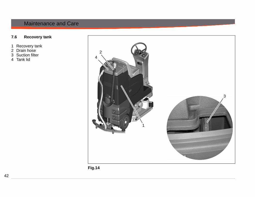
1 Recovery tank2 Drain hose3 Suction filter4 Tank lid
Fig.14
1
3
24
43
Maintenance and Care
7.6.1 Empty recovery tankClean recovery tank (Fig. 14/1) at daily intervals, as required or upon acoustic signal (increased vacuum motor speed).1. Take machine to appropriate area
for draining. 2. Park machine such that drain hose
reaches a drain aperture in the floor.3. Switch off machine.
Observe the legal provisions and the local regulations for disposal of detergents!
4. Take drain hose (Fig. 14/2) from holder and empty recovery tank completely.
7.6.2 Clean recovery tankClean recovery tank (Fig. 14/1) at daily intervals or as required.1. Empty recovery tank, see paragraph
7.6.1.2. Open tank lid (Fig. 14/4) of the recov-
ery tank.3. Take drain hose (Fig. 14/2) from
holder and empty recovery tank completely.
4. Remove remaining dirt by rinsing with clean water.
5. Rinse drain hose as well.
7.6.3 Clean Suction FilterCheck suction filter (Fig. 14/3) at daily intervals and clean if required. The suc-tion filter can be easily removed by pull-ing downward.

44
Maintenance and Care
7.7 Disc brush deck
1 Brush deck2 Roller bumper3 Deck cover4 Disc brush5 Side squeegee
Fig.15
7.7.1 Clean BrushesClean the brushes of the brush deck (Fig. 15/1) at daily intervals or as re-quired.1. Remove the deck cover (Fig. 15/3).
The deck cover can be removed without tools by removing the star shaped knobs
2. Push down on brush(Fig. 15/4) to re-move for cleaning.
7.7.2 Change BrushesCheck brushes and pads of the brush deck for wearing at daily intervals. Re-place brushes if bristles are worn down to a length of 1/2“. Replace pads if worn to 3/8”1. Push down to remove old brushes.2. Push new brush under brush deck,
line up the brush and brush hub, press brush onto brush hub firmly until snap is heard.
7.7.3 Change Roller BumperCheck roller bumper(Fig. 15/2) at week-ly intervals or replace as required.
7.7.4 Change side squeegeeCheck side squeegee (Fig. 15/5) at weekly intervals or as required. Re-move the two (front and back) wingnuts located behind the squeegee blades. Remove squeegee blade. Proceed to mounting in reverse order. Side squee-gee blades can be used fourfold by turning them.
12
3
4
5

45
Maintenance and Care
7.7.5 Adjust side squeegeeThe side squeegees channel the dirty solution to the rear squeegee. The side squeegees may require adjustments when replacing worn blades or to achieve optimum performance.1. Loosen the two (front and back)
wingnuts located behind the side-squeegee.
2. Lower the scrub deck by switching to a scrubbing mode and when the brushes start up, turn OFF the key switch.
3. At this point the side squeegee should be resting vertically (no de-flection) on the floor. Press down on the side squeegee bracket assembly from each end while making sure that the blade is uniformly deflected in a 45 degree angle along its whole length.
4. Tighten the wingnuts.5. Turn the steering wheel all the way to
the left or right and start pushing the machine to the side to inspect the blade deflection and wiping action.
6. Repeat the steps above until a satis-factory result is obtained.

46
Maintenance and Care
7.8 Cylindrical Brush Deck1 Brush deck2 Roller bumper3 Dirt hopper4 Side squeegee pivot bracket5 Brush hub6 Drive hub7 Notched end of cylindrical brush
Fig.16
7.8.1 Clean dirt hopperClean dirt hopper (Fig. 16/3) at daily in-tervals or as required.Remove dirt hopper by lifting and slid-ing sideways. Clean the hopper and re-place.
7.8.2 Remove brushes1. Remove the yellow star shaped knob
and swing the side squeegee brack-et (Fig. 16/4) along the hinge.
2. Release brush hub (Fig. 16/5) by re-moving the three thumbnuts.
3. Remove and check the brushes.
7.8.3 Clean brushesClean brushes in the brush deck at daily intervals or as required.
7.8.4 Replace brushesCheck brushes in the brush deck for wear at daily intervals and replace as required.1. Insert brush into brush deck and ro-
tate until it catches on the drive hub (notched end must face inward) (Fig. 16/6&7).
2. Place the brush hub and secure it with the three thumbnuts and lock washers.
3. Swing the side squeegee back into place and tighten the yellow star shaped knob.
7.8.5 Change roller bumperCheck roller bumpers (Fig. 16/2) at weekly intervals and replace if required.
12
3
4
5
6
7
47
Maintenance and Care
7.8.6 Adjust side squeegeeThe side squeegees channels the dirty solution to the rear squeegee, the side squeegees may require adjustments when replacing worn blades or to achieve optimum performance.1. Loosen the two black star shaped-
knobs.2. Lower the scrub deck by switching to
a scrubbing mode and when the brushes start up, turn OFF the key switch.
3. At this point the side squeegee should be resting vertically (no de-flection) on the floor. Press down on the side squeegee bracket assembly from each end while making sure that the blade is uniformly deflected in a 45 degree angle along its whole length.
4. Tighten the black star shaped knobs.5. Turn the steering wheel all the way to
the left or right and start pushing the machine to the side to inspect the blade deflection and wiping action.
6. Repeat the steps above until a satis-factory result is obtained.

48
Maintenance and Care
7.9 Rear Squeegee
1 Suction hose2 Squeegee blades3 Fastening latch4 Star-shaped knob5 Caster6 Washers for height adjustment
Fig.17
7.9.1 Cleaning the SqueegeeCheck the squeegee (Fig. 17/2) daily and clean as necessary.To clean, lift up the squeegee, pull off the suction hose (Fig. 17/1), loosen the two star-shaped knobs (Fig. 17/4) and remove the squeegee.
7.9.2 Change the Squeegee BladesCheck the inner and outer squeegee blades on the squeegee (Fig. 17/2) weekly for signs of wear. The squeegee blades can be used fourfold by turning them.1. Lift the squeegee up.2. Remove the suction hose, loosen
the two star-shaped knobs and re-move the squeegee.
3. Unlock the fastening latch (Fig. 17/3) and remove the outer squeegee blade. Turn the squeegee blade or install a new one. Change the inner squeegee blade in the same way.
1
2 54 63

49
Maintenance and Care
7.9.3 Adjusting the BladesAngle AdjustmentThe angle adjustment is the decisive factor in ensuring that the squeegee blades on the squeegee lie evenly on the floor.1. Park the machine on a level surface
and lower the squeegee.2. Loosen the pivot bolts (Fig. 17/1)
and adjust the squeegee using the adjusting nuts (Fig. 17/2) so that the ends of the squeegee blades contact the floor.Figure ATurn the adjusting nuts counter-clockwise: The clearance between squeegee blade and floor is reduced in the center.Figure BTurn the adjusting nuts clockwise: The clearance between the squee-gee blade and floor increases in the center
3. Switch the machine on and check the suction pattern. When the ma-chine is operating, the entire surface of the squeegee blades (center and outer areas) must be applied as evenly as possible.
4. Tighten the pivot bolts.Fig.18
B
A
1
1
2
50
Maintenance and Care
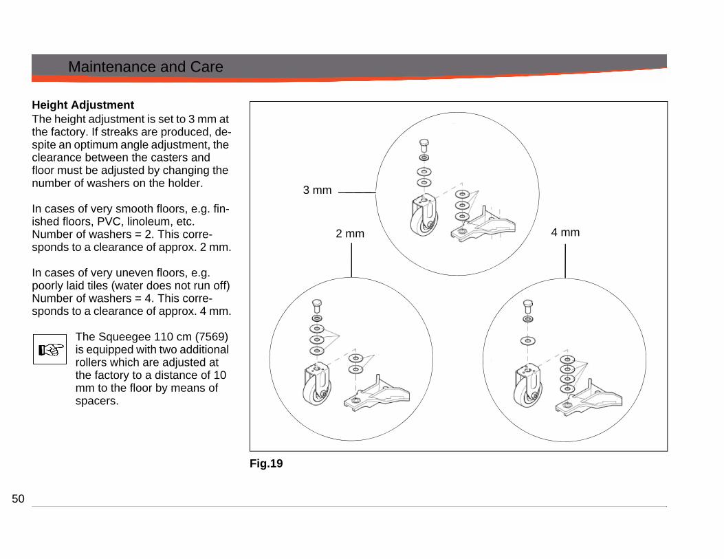
Height AdjustmentThe height adjustment is set to 3 mm at the factory. If streaks are produced, de-spite an optimum angle adjustment, the clearance between the casters and floor must be adjusted by changing the number of washers on the holder.
In cases of very smooth floors, e.g. fin-ished floors, PVC, linoleum, etc.Number of washers = 2. This corre-sponds to a clearance of approx. 2 mm.
In cases of very uneven floors, e.g. poorly laid tiles (water does not run off)Number of washers = 4. This corre-sponds to a clearance of approx. 4 mm.
The Squeegee 110 cm (7569) is equipped with two additional rollers which are adjusted at the factory to a distance of 10 mm to the floor by means of spacers.
Fig.19
3 mm
2 mm 4 mm

51
Maintenance and Care
7.9.4 Adjusting lift mechanism
The squeegee lift mechanism lifts and lowers the squeegee, adjusts the angle, as well as controls the parallel motion.
The squeegee mechanism is pre ad-justed at the factory for optimal perfor-mance (Fig. 20).
-
Fig.20

52
Maintenance and Care
7.10 Machine LubricationRegularly scheduled lubrication of cer-tain machine parts should be performed to insure trouble-free operation of the machine. The grease points are listed below:• Rear squeegee caster axle (2)• Steering wheel chain sprockets and
idlers• Squeegee lift mechanism joints and
pivot points (Fig. 21/X)
Apply lubricant or light machine oil to lu-bricate the:• Rear squeegee general pivot points• Scrub deck linkages• Drive wheel assembly seals
Fig.21

53
Maintenance and Care
Notes

54
Troubleshooting
8 TroubleshootingProblem Possible Cause Remedy
Poor water pick-up Worn or torn squeegee blades Rotate or replace blades
Squeegee out of adjustment Adjust so blades touch floor evenly across entire width
Recovery tank full Empty recovery tankRecovery tank drain hose leak Secure drain hose cap or replaceRecovery tank lid gasket leak Replace gasket lid cover properlyDebris caught in squeegee Clean squeegee Vacuum hose clogged Remove debris and flush hoseUsing too much solution Adjust solution control valvesVacuum hose to squeegee or recovery tank disconnected to squeegee or dam-aged
Reconnect or replace squeegee hose
Poor scrubbing performance Worn brushes Rotate or replace brushesWrong brush or cleaning chemical Consult PowerBossDebris caught on scrub brushes Remove debrisMoving machine too fast Slow downLow battery charge Recharge batteries
No solution to off-aisle wand spray jet Solution tank empty Refill solution tankNo FWD/REV drive Drive system speed controller. Check error fault codes

55
Troubleshooting
Problem Possible Cause RemedyInadequate solution flow or no solution to the floor
Solution tank empty Fill solution tank
Recovery tank full Empty recovery tankSolution lines, valves, filter or spray jets clogged
Flush lines, and clean solution filter and spray jets.
Solution solenoid valve Clean or replace valveMachine does not run Operator seat safety switch Operator has to be seated.Check for
open circuit Main system controller Check error fault codesTripped 100 amp circuit breaker Check for an electrical short circuit.
Reset machine: Reset breaker and turn
key switch off and restart.Vacuum motor does not turn on Recovery tank full Empty recovery tank
Excessive foaming in recovery tank. Empty recovery tank.Use less or change chemicalUse defoaming agent
Five LEDs flashing on Battery Gauge Check for motor overloadReset machine: Turn key switch off and restart.
Poor sweeping performance (cylindrical) Debris box full Empty and clean debris boxBrushes worn Replace brushesBristles have taken a set Rotate brushes

56
Revision FEffictive November 1, 2008Powerboss made Simple Industrial Limited WarrantyMinuteman International owner of PowerBoss warrants to the original purchaser/user that the product is free from defects in workmanshipand materials under normal use. PowerBoss will, at its option, repair or replace without charge, parts that fail under normal use and servicewhen operated and maintained in accordance with the applicable operation and instruction manuals. All warranty claims must be submittedthrough and approved by factory authorized repair stations.
This warranty does not apply to normal wear, or to items whose life is dependent on their use and care. Parts not manufactured byPowerBoss are covered by and subject to the warranties and/or guarantees of their manufacturers. Please contact Minuteman Internationalfor procedures in warranty claims against these manufacturers.
Special warning to purchaser — Use of replacement parts not manufactured by PowerBoss or its designated licensees, will void allwarranties expressed or implied. A potential health hazard exits without original equipment replacement.
All warranted items become the sole property of Minuteman International or PowerBoss or its original manufacturer, whichever the casemay be.
PowerBoss disclaims any implied warranty, including the warranty of merchantability and the warranty of fitness for a particular purpose.PowerBoss assumes no responsibility for any special, incidental or consequential damages.
This limited warranty is applicable only in the U.S.A. and Canada, and is extended only to the original user/purchaser of this product.Customers outside the U.S.A. and Canada should contact their local distributor for export warranty policies. PowerBoss is not responsiblefor costs or repairs performed by persons other than those specifically authorized by PowerBoss. This warranty does not apply to damagefrom transportation, alterations by unauthorized persons, misuse or abuse of the equipment, use of non-compatible chemicals, or damageto property, or loss of income due to malfunctions of the product. If a difficulty develops with this machine, you should contact the dealerfrom whom it was purchased.
This warranty gives you specific legal rights, and you may have other rights, which vary from state to state. Some states do not allow theexclusion or limitation of special, incidental or consequential damages, or limitations on how long an implied warranty lasts, so the aboveexclusions and limitations may not apply to you.
PowerBoss Incorporated Made Simple Commercial Limited Warranty

57
Travel* Labor Parts Engine Extended Warranty CostsWalk behindsBattery sweepers Ninety days One year One year N/A 2 years Parts + Labor (or 2000 Hours) 2%IC sweepers Ninety days One year One year Through manufacturer 2 years Parts + Labor (or 2000 Hours) 2%Battery scrubbers Ninety days Two years Three years N/A 3 Years Parts + Labor (or 3000 Hours) 2%
RidersBattery scrubbers Ninety days Two years Three years/2000 hrs N/A 3 Years Parts + Labor (or 3000 Hours) 2%IC sweeper/scrubbers Ninety days Six months Two years/2000 hrs Two years/3000 hrs** 2 years Parts + Labor (or 2000 Hours) 3%IC sweepers Ninety days Six months Four years/3000 hrs Five years/3000 hrs**
ExceptionsApex series sweeper Ninety days One year One year/1000 hrs One year/1000 hrs** 2 years Parts + Labor (or 2000 Hours) 3%6X sweeper Ninety days Six months Two years/2000 hrs Two years/2000 hours** 2 years Parts + Labor (or 2000 Hours) 3%
4 Years Parts + 2 Years Labor (or 4000 Hours) 3%
Tank Bladders Eight years/ no additional labor Polypropylene plastic tanks Ten years/ no additional labor Batteries 0-3 months full replacement, 4-12 prorated credit Chargers One-year replacement Replacement parts Ninety days *Two-hour cap **Through engine manufacturer. See section 3 of warranty manual for engine warranty exceptions *** Based upon dealer’s certification status Extended Warranty MUST be signed up within 30 days of delivery to End User (Dealer has 1Year from Receiving Machine to Sign up extended Warranty) Extended Warranty Cost is based on Invoice Price multiplied by the Percentage listed in the Extended Warranty Column

58

59

PowerBoss Incorporated. · 175 Anderson Street P.O. Box 1227· Aberdeen, North Carolina 28315 · U.S.A.Phone: 1-800-982-7141 · Fax 1-800-277-7141 · Local 1-910-944-7409
www.powerboss.com
A Member of the Hako Group
988726umpb R
EV
A 10/11