89uf/df - hydrotechwater.com hydrotech... · owners manual against nsf/ansi 44 89uf/df series* ......
TRANSCRIPT
Canada West855 Park St., Unit 1Regina, SK S4N 6M1
Canada East490 Pinebush Rd., Unit 1Cambridge, ON N1T 0A5
U.S.A.56 Lightcap Rd.Pottstown, PA 19464
9760 Mayflower Park Drive, Suite 110Carmel, IN 46032
4655 McDowell Rd. W Phoenix, AZ 85035
IAPMO R & T Certified against CSA B483.1
IAPMO R & T Certified against NSF/ANSI 44
Owne
rs M
anua
l
89UF/DF Series* Water Softener
1. Page 25 of this manual contains important maintenance procedures for the continued proper operation of your unit. These MUST be performed regularly for your warranty to remain valid.2. Read all instructions carefully before operation.3. Avoid pinched o-rings during installation by applying NSF certified lubricant to all seals (provided with install kit).4. This system is not intended for treating water that is microbiologically unsafe or of unknown quality without adequate disinfection before or after the system.
*Check the valve sticker
to make sure its UF (Upflow) or DF (Downflow)
Tabl
e of C
onte
nts
3
Tabl
e of C
onte
nts READ THIS PAGE FIRST
BEFORE STARTING INSTALLATION 4
EFFICIENCY STATEMENT 5
HOW YOUR WATER CONDITIONER WORKS 5
SPECIFICATIONS SPECIFICATION 6SYSTEM DIMENSIONS 7BRINE TANK DIMENSIONS 8
INSTALLATION UNPACKING / INSPECTION OF TWIN TANK MODEL 10UNPACKING / INSPECTION OF CABINET MODEL 12BEFORE INSTALLATION 14PREPARATIONS 15INSTALLING BRINE TANK 17 WATER SOFTENER INSTALLATION - UPFLOW 18 WATER SOFTENER INSTALLATION - DOWNFLOW 19CABINET WATER SOFTENER INSTALLATION - UPFLOW 20CABINET WATER SOFTENER INSTALLATION - DOWNFLOW 21
STARTUP INSTRUCTIONS 22
DURING REGENERATION 24 PLUMBING SYSTEM CLEAN-UP 24
MAINTENANCE INSTRUCTIONS AND SCHEDULE 25
IMPORTANT WARRANTY AND MAINTENANCE INFORMATION 26
RES-UP® FEEDER INSTALLATION INSTRUCTIONS 27
SERVICING 89HE VALVE 29
REPLACEMENT TIMER REPLACEMENT 30PISTON AND/OR BRINE VALVE ASSEMBLY REPLACEMENT 30 METER ASSEMBLY REPLACEMENT 31REPLACING THE BYPASS AND METER CABLE 32CLEAN INJECTOR ASSEMBLY 33 REPLACE MOTOR 33 REPLACE MICROSWITCHES 33CIRCUIT BOARD REPLACEMENT 34 REPLACE BRINE LINE FLOW CONTROL 34 REPLACE DRAIN LINE FLOW CONTROL 34
AFTER SERVICING 35
PARTS BREAKDOWN 35
PARTS POWERHEAD / BYPASS 37VALVE BODY 38DLFC PART # FOR 89 VALVE / BLFC PART # FOR 89 VALVE /INJECTOR PART # FOR 89 VALVE 39CABINET 40
TROUBLE SHOOTING GUIDE 41
PROGRAMMING 42
4
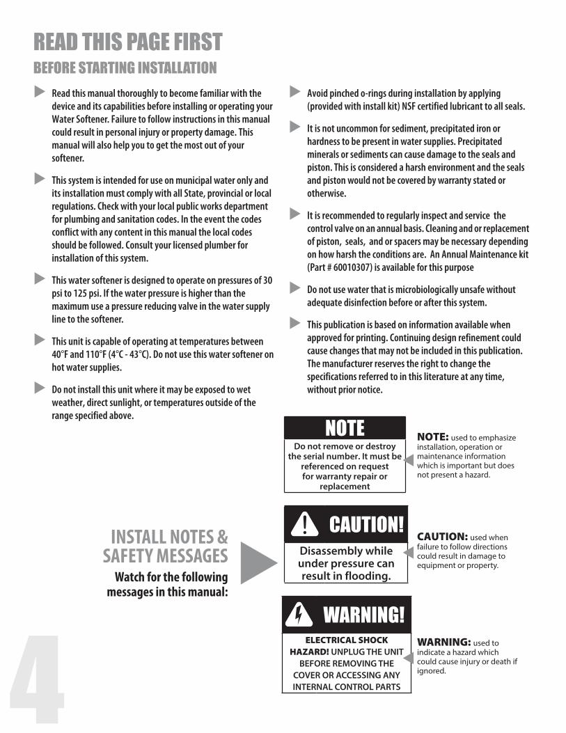
READ THIS PAGE FIRST BEFORE STARTING INSTALLATIONRead this manual thoroughly to become familiar with the device and its capabilities before installing or operating your Water Softener. Failure to follow instructions in this manual could result in personal injury or property damage. This manual will also help you to get the most out of your softener.
This system is intended for use on municipal water only and its installation must comply with all State, provincial or local regulations. Check with your local public works department for plumbing and sanitation codes. In the event the codes conflict with any content in this manual the local codes should be followed. Consult your licensed plumber for installation of this system.
This water softener is designed to operate on pressures of 30 psi to 125 psi. If the water pressure is higher than the maximum use a pressure reducing valve in the water supply line to the softener.
This unit is capable of operating at temperatures between 40°F and 110°F (4°C - 43°C). Do not use this water softener on hot water supplies.
Do not install this unit where it may be exposed to wet weather, direct sunlight, or temperatures outside of the range specified above.
Avoid pinched o-rings during installation by applying (provided with install kit) NSF certified lubricant to all seals.
It is not uncommon for sediment, precipitated iron or hardness to be present in water supplies. Precipitated minerals or sediments can cause damage to the seals and piston. This is considered a harsh environment and the seals and piston would not be covered by warranty stated or otherwise.
It is recommended to regularly inspect and service the control valve on an annual basis. Cleaning and or replacement of piston, seals, and or spacers may be necessary depending on how harsh the conditions are. An Annual Maintenance kit (Part # 60010307) is available for this purpose
Do not use water that is microbiologically unsafe without adequate disinfection before or after this system.
This publication is based on information available when approved for printing. Continuing design refinement could cause changes that may not be included in this publication. The manufacturer reserves the right to change the specifications referred to in this literature at any time, without prior notice.
INSTALL NOTES &SAFETY MESSAGES
Watch for the following messages in this manual:
NOTEDo not remove or destroy
the serial number. It must be referenced on request for warranty repair or
replacement
CAUTION!Disassembly while under pressure can result in flooding.
WARNING!ELECTRICAL SHOCK
HAZARD! UNPLUG THE UNIT BEFORE REMOVING THE
COVER OR ACCESSING ANY INTERNAL CONTROL PARTS
NOTE: used to emphasize installation, operation or maintenance information which is important but does not present a hazard.
CAUTION: used when failure to follow directions could result in damage to equipment or property.
WARNING: used to indicate a hazard which could cause injury or death if ignored.
4 5
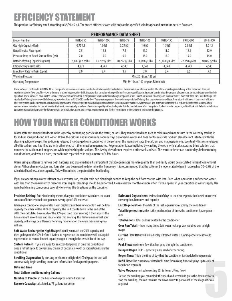
PERFORMANCE DATA SHEETModel Number 89HE-75C 89HE-100C 89HE-75 89HE-100 89HE-150 89HE-200 89HE-300Qty High Capacity Resin 0.75 ft3 1.0 ft3 0.75 ft3 1.0 ft3 1.5 ft3 2.0 ft3 3.0 ft3Rated Service Flow (gpm) 7.5 12.1 7.5 11.0 11.2 12.4 12.9Pressure Drop at Rated Service Flow (psi) 7.0 15.0 9.0 15.0 15.0 15.0 15.0Rated Softening Capacity (grains) 9,609 @ 2.25lbs 13,269 @ 3lbs 10,222 @3lbs 13,269 @ 3lbs 20,443 @4.5lbs 27,258 @6lbs 40,887 @9lbsEfficiency (grains/lb salt) 4,271 4,543 4,543 4,543 4,543 4,543 4,543Max. Flow Rate to Drain (gpm) 2.0 2.4 1.5 2.0 2.4 3.5 5.0Working Pressure Min. 20 - Max. 125 psiOperating Temperature Min 39 - Max. 100 degrees Fahrenheit
EFFICIENCY STATEMENTThis product is efficiency rated according to NSF/ANSI 44. The stated efficiencies are valid only at the specified salt dosages and maximum service flow rate.
These softeners conform to NSF/ANSI 44 for the specific performance claims as verified and substantiated by test data. These models are efficiency rated. The efficiency rating is valid only at the stated salt dose and maximum service flow rate. They have a demand initiated regeneration (D.I.R.) feature that complies with specific performance specifications intended to minimize the amount of regenerant brine and water used in their operation. These softeners have a rated softener efficiency of not less than 3350 grains of total hardness exchange per pound of salt (based on sodium chloride) and shall not deliver more salt than their listed ratings. The rated salt efficiency is measured bylaboratory tests described in NSF/ANSI Standard 44. These tests represent the maximum possible efficiency that the systems can achieve. Operational efficiency is the actual efficiency after the system has been installed. It is typically less than the efficiency due to individual application factors including water hardness, water usage, and other contaminants that reduce the softener’s capacity. These systems are not intended for use with water that is microbiologically unsafe or of unknown quality without adequate disinfection before or after the system. For best results, use plain, white block salt. Refer to Installation/operation manual and warranty for further details on installation, parts and service, maintenance and further restrictions or limitations to the use of the product.
HOW YOUR WATER CONDITIONER WORKS Water softeners remove hardness in the water by exchanging particles in the water, or ions. They remove hard ions such as calcium and magnesium in the water by trading it for sodium ions producing soft water. Unlike the calcium and magnesium, sodium stays dissolved in water and does not form a scale. Sodium also does not interfere with the cleaning action of soaps. The sodium is released by a charged resin contained in the softener, this resin also traps the calcium and magnesium ions. Eventually this resin releases all of its sodium and has filled up with other ions, so it then must be regenerated. Regeneration is accomplished by washing the resin with a salt saturated brine solution that removes the calcium and magnesium while replenishing the sodium. This is why the softener requires a brine tank and salt. The water softener can run for days before running out of sodium, and when it does, the sodium is replenished in only a matter of a few hours
When using a softener to remove both hardness and dissolved iron it is important that it regenerates more frequently than ordinarily would be calculated for hardness removal alone. Although many factors and formulas have been used to determine this frequency, it is recommended that the softener be regenerated when it has reached 50–75% of the calculated hardness alone capacity. This will minimize the potential for bed fouling. If you are operating a water softener on clear water iron, regular resin bed cleaning is needed to keep the bed from coating with iron. Even when operating a softener on water with less than the maximum of dissolved iron, regular cleanings should be performed. Clean every six months or more often if iron appears in your conditioned water supply. Use resin bed cleaning compounds carefully following the directions on the container.
Precision Brining: Precision brining means that your conditioner calculates the exact amount of brine required to regenerate saving up to 30% more salt
When your conditioner regenerates it will display 2 numbers for capacity 1 will be total capacity the other will be 70 % of capacity. The unit counts down to the end of the 70% then calculates how much of the 30% you used (your reserve) it then adjusts the brine amount accordingly and regenerates that evening. This feature means that your capacity will always be different after every regeneration therefore maximizing your salt use.
Soft Water Recharge for High Usage: Should you reach the 70% capacity and then go beyond the 30% before it is time to regenerate the conditioner will do a quick regeneration to restore limited capacity to get it through the remainder of the day.
System Refresh: If you are away for an extended period of time the Conditioner does a refresh cycle to prevent any chance of bacterial growth or stagnation inside the conditioner.
Scrolling Diagnostics: By pressing any button to light the LCD display the unit will automatically begin scrolling important information for diagnostic purposes
Date and TimeTotal Gallons and Remaining GallonsNumber of People: in the household as programmed at install
Reserve Capacity: calculated as 75 gallons per person
Estimated Days to Next: estimation of days to the next regeneration based on current consumption, hardness and capacity
Last Regeneration: the date of the last regeneration cycle by the conditioner
Total Regenerations: this is the total number of times the conditioner has regener-ated
Total Gallons: total gallons treated by the conditioner
Over Run Total: – how many times Soft water recharge was required due to high usage
Current Flow Rate: will only display if treated water is running otherwise it would read 0
Peak Flow: maximum flow that has gone through the conditioner.
Delayed Regen OFF: – generally only used after servicing.
Regen Time: This is the time of day that the conditioner is scheduled to regenerate
Refill Time: The current calculated refill time for makeup brine (displays up to 70% of total brine required)
Valve Mode: current valve setting EG. Softener UF (up flow)
To stop the scrolling you can unlock the board as directed and press the down arrow to stop the scrolling. You can then use the down arrow to go to each of the diagnostics as required.
6
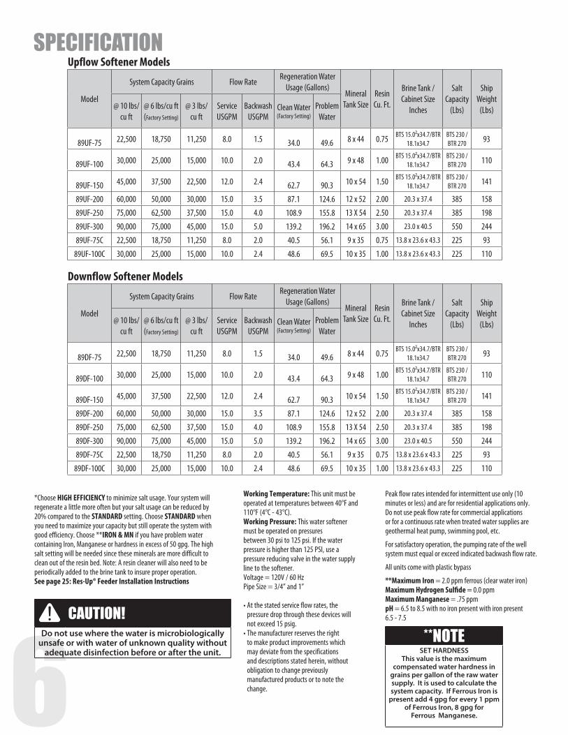
Upflow Softener Models
Model
System Capacity Grains Flow Rate Regeneration Water
Usage (Gallons)Mineral
Tank Size Resin Cu. Ft.
Brine Tank / Cabinet Size
Inches
Salt Capacity
(Lbs)
Ship Weight
(Lbs)@ 10 lbs/cu ft
@ 6 lbs/cu ft (Factory Setting)
@ 3 lbs/cu ft
Service USGPM
Backwash USGPM
Clean Water (Factory Setting)
Problem Water
89UF-75 22,500 18,750 11,250 8.0 1.5 34.0 49.6 8 x 44 0.75 BTS 15.0²x34.7/BTR 18.1x34.7
BTS 230 /BTR 270 93
89UF-100 30,000 25,000 15,000 10.0 2.0 43.4 64.3 9 x 48 1.00 BTS 15.0²x34.7/BTR 18.1x34.7
BTS 230 /BTR 270 110
89UF-150 45,000 37,500 22,500 12.0 2.4 62.7 90.3 10 x 54 1.50 BTS 15.0²x34.7/BTR 18.1x34.7
BTS 230 /BTR 270 141
89UF-200 60,000 50,000 30,000 15.0 3.5 87.1 124.6 12 x 52 2.00 20.3 x 37.4 385 158
89UF-250 75,000 62,500 37,500 15.0 4.0 108.9 155.8 13 X 54 2.50 20.3 x 37.4 385 198
89UF-300 90,000 75,000 45,000 15.0 5.0 139.2 196.2 14 x 65 3.00 23.0 x 40.5 550 244
89UF-75C 22,500 18,750 11,250 8.0 2.0 40.5 56.1 9 x 35 0.75 13.8 x 23.6 x 43.3 225 93
89UF-100C 30,000 25,000 15,000 10.0 2.4 48.6 69.5 10 x 35 1.00 13.8 x 23.6 x 43.3 225 110
Downflow Softener Models
Model
System Capacity Grains Flow Rate Regeneration Water
Usage (Gallons)Mineral
Tank Size Resin Cu. Ft.
Brine Tank / Cabinet Size
Inches
Salt Capacity
(Lbs)
Ship Weight
(Lbs)@ 10 lbs/cu ft
@ 6 lbs/cu ft (Factory Setting)
@ 3 lbs/cu ft
Service USGPM
Backwash USGPM
Clean Water (Factory Setting)
Problem Water
89DF-75 22,500 18,750 11,250 8.0 1.5 34.0 49.6 8 x 44 0.75 BTS 15.0²x34.7/BTR 18.1x34.7
BTS 230 /BTR 270 93
89DF-100 30,000 25,000 15,000 10.0 2.0 43.4 64.3 9 x 48 1.00 BTS 15.0²x34.7/BTR 18.1x34.7
BTS 230 /BTR 270 110
89DF-150 45,000 37,500 22,500 12.0 2.4 62.7 90.3 10 x 54 1.50 BTS 15.0²x34.7/BTR 18.1x34.7
BTS 230 /BTR 270 141
89DF-200 60,000 50,000 30,000 15.0 3.5 87.1 124.6 12 x 52 2.00 20.3 x 37.4 385 158
89DF-250 75,000 62,500 37,500 15.0 4.0 108.9 155.8 13 X 54 2.50 20.3 x 37.4 385 198
89DF-300 90,000 75,000 45,000 15.0 5.0 139.2 196.2 14 x 65 3.00 23.0 x 40.5 550 244
89DF-75C 22,500 18,750 11,250 8.0 2.0 40.5 56.1 9 x 35 0.75 13.8 x 23.6 x 43.3 225 93
89DF-100C 30,000 25,000 15,000 10.0 2.4 48.6 69.5 10 x 35 1.00 13.8 x 23.6 x 43.3 225 110
SPECIFICATION
Working Temperature: This unit must be operated at temperatures between 40°F and 110°F (4°C - 43°C). Working Pressure: This water softener must be operated on pressures between 30 psi to 125 psi. If the water pressure is higher than 125 PSI, use a pressure reducing valve in the water supply line to the softener. Voltage = 120V / 60 HzPipe Size = 3/4” and 1”
• At the stated service flow rates, the pressure drop through these devices will not exceed 15 psig.
• The manufacturer reserves the right to make product improvements which may deviate from the specifications and descriptions stated herein, without obligation to change previously manufactured products or to note the change.
*Choose HIGH EFFICIENCY to minimize salt usage. Your system will regenerate a little more often but your salt usage can be reduced by 20% compared to the STANDARD setting. Choose STANDARD when you need to maximize your capacity but still operate the system with good efficiency. Choose **IRON & MN if you have problem water containing Iron, Manganese or hardness in excess of 50 gpg. The high salt setting will be needed since these minerals are more difficult to clean out of the resin bed. Note: A resin cleaner will also need to be periodically added to the brine tank to insure proper operation.See page 25: Res-Up® Feeder Installation Instructions
Peak flow rates intended for intermittent use only (10 minutes or less) and are for residential applications only. Do not use peak flow rate for commercial applications or for a continuous rate when treated water supplies are geothermal heat pump, swimming pool, etc.
For satisfactory operation, the pumping rate of the well system must equal or exceed indicated backwash flow rate.
All units come with plastic bypass
**Maximum Iron = 2.0 ppm ferrous (clear water iron)Maximum Hydrogen Sulfide = 0.0 ppmMaximum Manganese = .75 ppmpH = 6.5 to 8.5 with no iron present with iron present 6.5 - 7.5 CAUTION!
Do not use where the water is microbiologically unsafe or with water of unknown quality without
adequate disinfection before or after the unit.**NOTE
SET HARDNESS This value is the maximum
compensated water hardness in grains per gallon of the raw water supply. It is used to calculate the system capacity. If Ferrous Iron is
present add 4 gpg for every 1 ppm of Ferrous Iron, 8 gpg for
Ferrous Manganese.
6 7
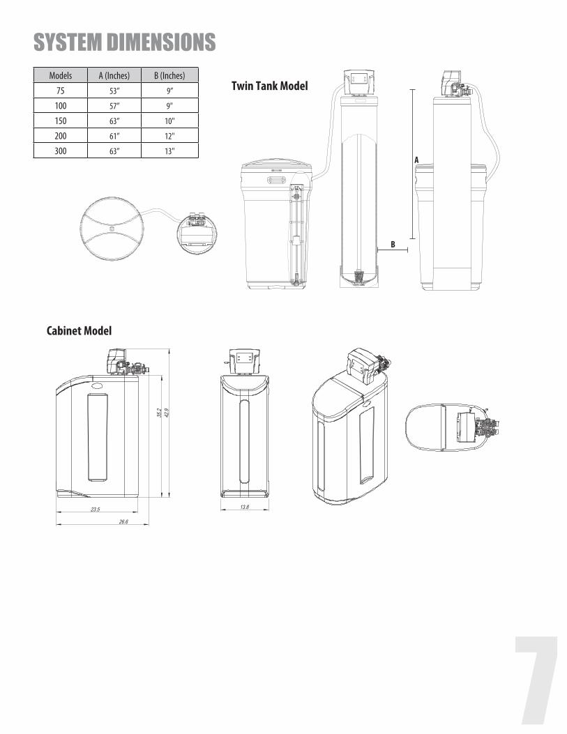
Cabinet Model
B
Twin Tank Model
A
Models A (Inches) B (Inches)75 53” 9”
100 57” 9"
150 63” 10"
200 61” 12"
300 63” 13"
SYSTEM DIMENSIONS

8
Model Color Liquid Volume Tank Dimensions (inches)
5 Pack Carton Dimensions (inches)
Salt Capacity 5 Pack Carton Shipping Weight
US Gal Liters L x W x H L x W x H Lbs Kg Lbs KgBrine Tanks
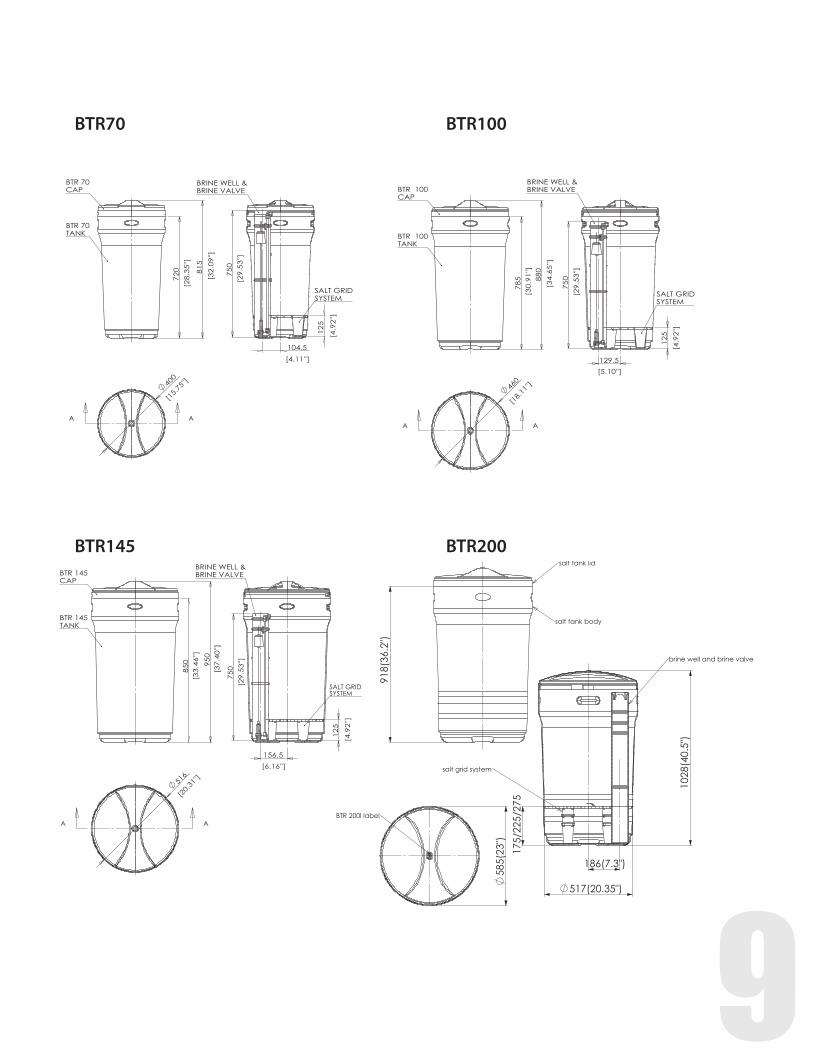
BTR-70 Black 20.3 76.5 15.8 x 32.1 16.7 x 16.7 x 61.0 185.0 92.8 41.6 18.9
BTR-70 Blue 20.3 76.7 15.8 x 32.1 16.7 x 16.7 x 61.0 185.0 92.8 41.6 18.9
BTR-100 Vanilla 29.5 111.5 18.1 x 34.7 18.9 x 18.9 x 65.6 270.0 122.2 52.8 23.9
BTR-100 Black 29.5 111.5 18.1 x 34.7 18.9 x 18.9 x 65.6 270.0 122.2 52.8 23.9
BTR-100 Blue 29.5 111.5 18.1 x 34.7 18.9 x 18.9 x 65.6 270.0 122.2 52.8 23.9
BTR-145 Black 42.3 159.7 20.3 x 37.4 21.9 x 21.9 x 72.2 385.0 174.2 65.6 29.8
BTR-200 Grey 53.0 200.3 23.0 x 40.5 24.6 x 24.6 x 84 700.0 316.7 125.0 56.6
BTS-70 Black 19.0 71.8 13.1 x 13.1 x 34.7 14.4 x 14.4 x 62 175.0 92.8 48.8 22.1
BTS-70 Blue 19.0 71.8 13.1 x 13.1 x 34.7 14.4 x 14.4 x 62 175.0 92.8 48.8 22.1
BTS-100 Vanilla 25.0 94.5 15.0 x 15.0 x 34.7 16.6 x 16.7 x 61 230.0 104.1 54.4 24.7
BTS-100 Black 25.0 94.5 15.0 x 15.0 x 34.7 16.6 x 16.7 x 61 230.0 104.1 54.4 24.7
BTS-100 Blue 25.0 94.5 15.0 x 15.0 x 34.7 16.6 x 16.7 x 61 230.0 104.1 54.4 24.7
* All brine tanks come with salt grid, safety float and brine well
DimensionsBTS70
BTS100
BRINE TANK DIMENSIONS
8 9
175/
225/
275
salt grid system
918(
36.2
")
salt tank body
salt tank lid
(7.3")
(20.35")
1028
186
(40.
5")
517
175/
225/
275
brine well and brine valve
salt grid system
585(
23")
BTR 200l label
BTR70
BTR145
BTR100
BTR200
10
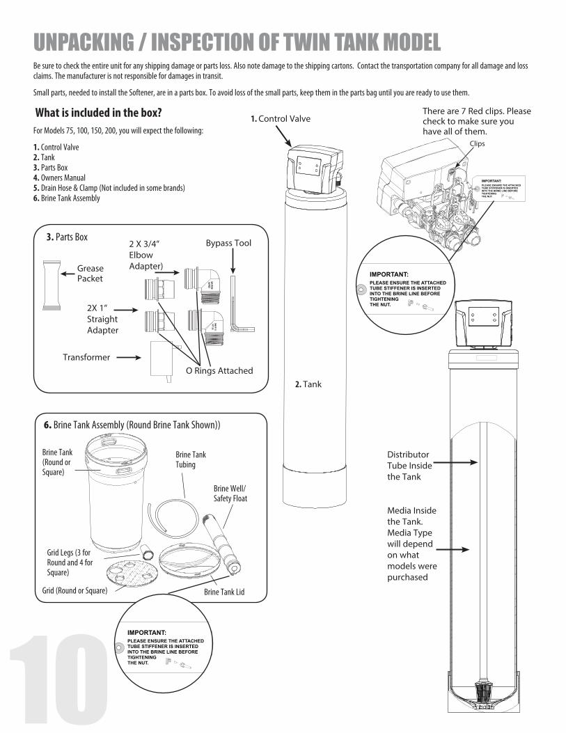
3. Parts Box
2X 1” Straight Adapter
Bypass Tool
O Rings Attached
2 X 3/4” Elbow Adapter)
Transformer
Grease Packet
Brine Tank (Round or Square)
Brine Tank Tubing
Brine Well/Safety Float
Brine Tank LidGrid (Round or Square)
Grid Legs (3 for Round and 4 for Square)
6. Brine Tank Assembly (Round Brine Tank Shown))
There are 7 Red clips. Please check to make sure you have all of them.
Distributor Tube Inside the Tank
Media Inside the Tank. Media Type will depend on what models were purchased
Clips
1. Control Valve
Be sure to check the entire unit for any shipping damage or parts loss. Also note damage to the shipping cartons. Contact the transportation company for all damage and loss claims. The manufacturer is not responsible for damages in transit.
Small parts, needed to install the Softener, are in a parts box. To avoid loss of the small parts, keep them in the parts bag until you are ready to use them.
What is included in the box?For Models 75, 100, 150, 200, you will expect the following:
1. Control Valve 2. Tank 3. Parts Box 4. Owners Manual 5. Drain Hose & Clamp (Not included in some brands) 6. Brine Tank Assembly
UNPACKING / INSPECTION OF TWIN TANK MODEL
2. Tank
10 11
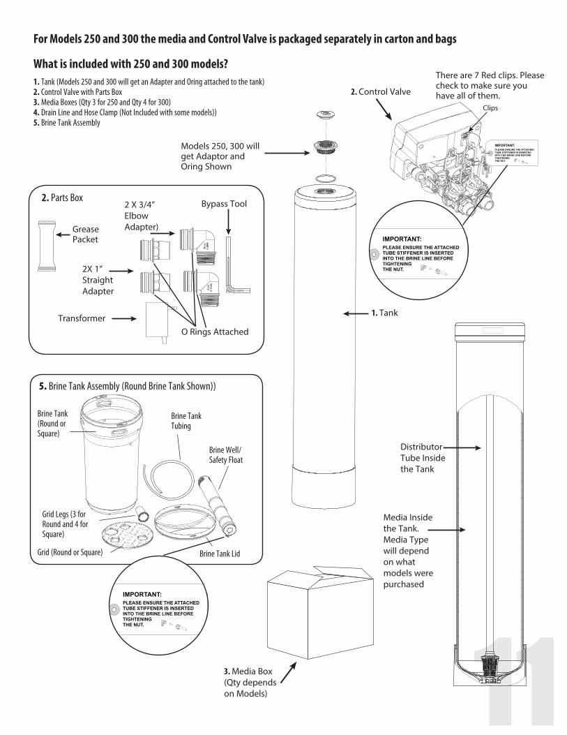
2. Parts Box
2X 1” Straight Adapter
Bypass Tool
O Rings Attached
2 X 3/4” Elbow Adapter)
Transformer
Grease Packet
Brine Tank (Round or Square)
Brine Tank Tubing
Brine Well/Safety Float
Brine Tank LidGrid (Round or Square)
Grid Legs (3 for Round and 4 for Square)
5. Brine Tank Assembly (Round Brine Tank Shown))
There are 7 Red clips. Please check to make sure you have all of them.
Clips
Distributor Tube Inside the Tank
Media Inside the Tank. Media Type will depend on what models were purchased
3. Media Box (Qty depends on Models)
2. Control Valve
For Models 250 and 300 the media and Control Valve is packaged separately in carton and bags
What is included with 250 and 300 models?1. Tank (Models 250 and 300 will get an Adapter and Oring attached to the tank) 2. Control Valve with Parts Box 3. Media Boxes (Qty 3 for 250 and Qty 4 for 300) 4. Drain Line and Hose Clamp (Not Included with some models)) 5. Brine Tank Assembly
Models 250, 300 will get Adaptor and Oring Shown
1. Tank
12
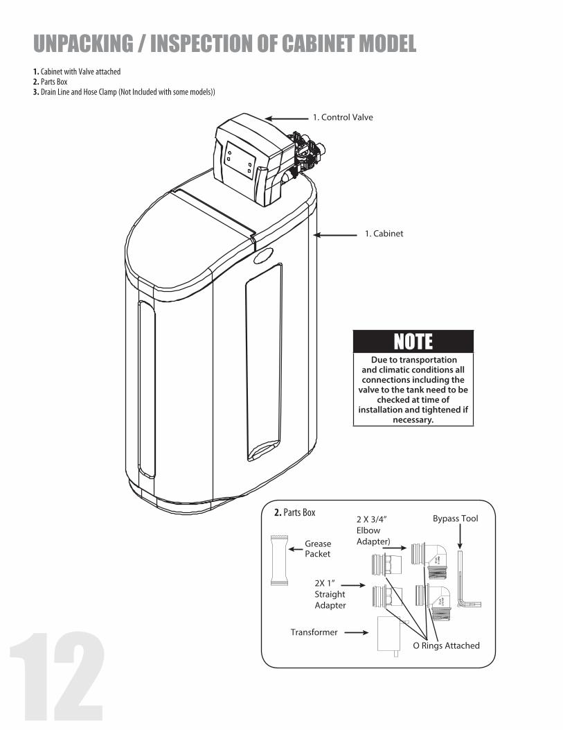
1. Control Valve
1. Cabinet
2. Parts Box
2X 1” Straight Adapter
Bypass Tool
O Rings Attached
2 X 3/4” Elbow Adapter)
Transformer
Grease Packet
NOTE Due to transportation
and climatic conditions all connections including the
valve to the tank need to be checked at time of
installation and tightened if necessary.
UNPACKING / INSPECTION OF CABINET MODEL1. Cabinet with Valve attached 2. Parts Box 3. Drain Line and Hose Clamp (Not Included with some models))
12 13
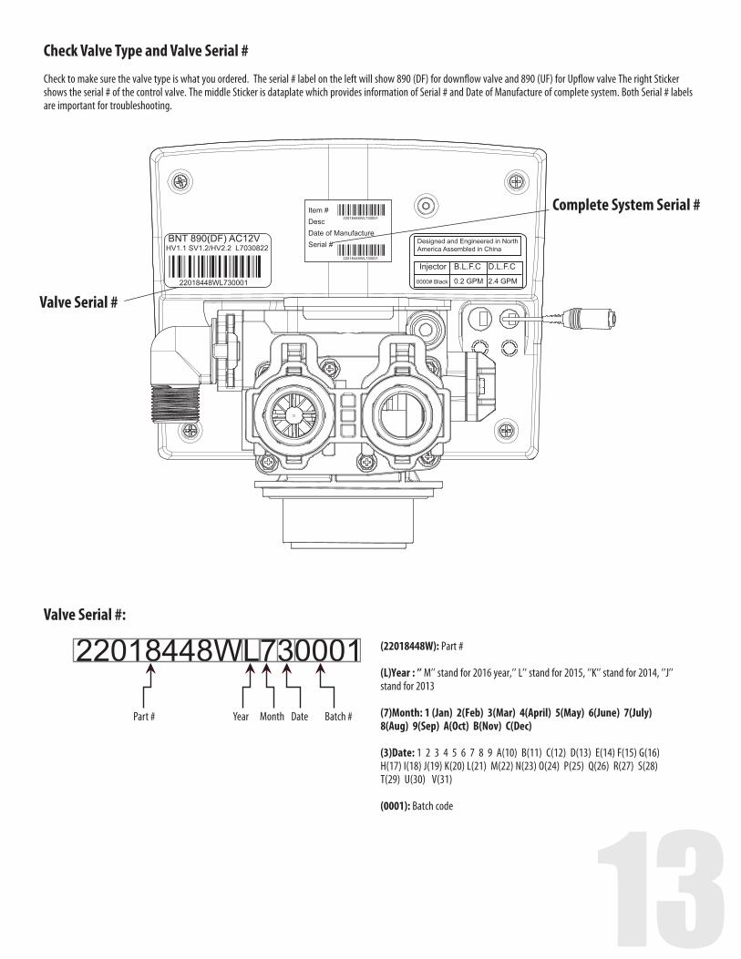
(22018448W): Part #
(L)Year : ’’ M’’ stand for 2016 year,’’ L’’ stand for 2015, ’’K’’ stand for 2014, ’’J’’ stand for 2013
(7)Month: 1 (Jan) 2(Feb) 3(Mar) 4(April) 5(May) 6(June) 7(July) 8(Aug) 9(Sep) A(Oct) B(Nov) C(Dec)
(3)Date: 1 2 3 4 5 6 7 8 9 A(10) B(11) C(12) D(13) E(14) F(15) G(16) H(17) I(18) J(19) K(20) L(21) M(22) N(23) O(24) P(25) Q(26) R(27) S(28) T(29) U(30) V(31) (0001): Batch code
Check Valve Type and Valve Serial #
Check to make sure the valve type is what you ordered. The serial # label on the left will show 890 (DF) for downflow valve and 890 (UF) for Upflow valve The right Sticker shows the serial # of the control valve. The middle Sticker is dataplate which provides information of Serial # and Date of Manufacture of complete system. Both Serial # labels are important for troubleshooting.
Valve Serial #:
Valve Serial #
Complete System Serial #
Year Month Date Batch #Part #
Item #DescDate of ManufactureSerial #
14
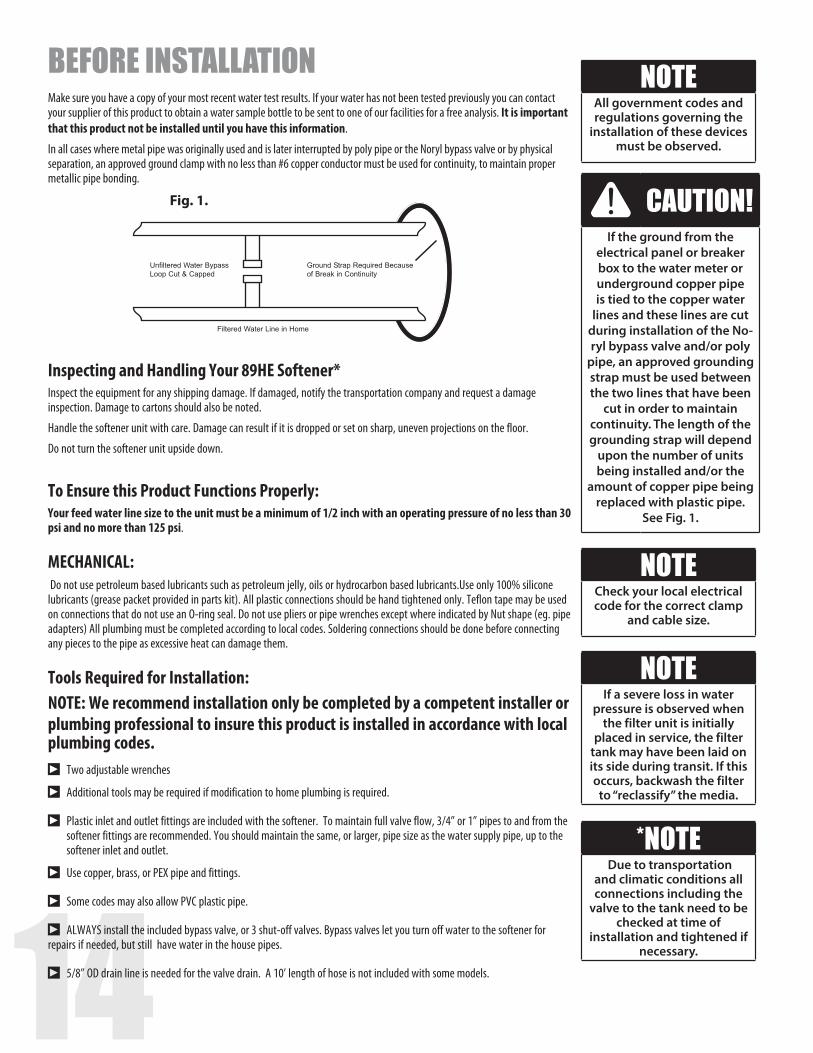
Fig. 1.
BEFORE INSTALLATIONMake sure you have a copy of your most recent water test results. If your water has not been tested previously you can contact your supplier of this product to obtain a water sample bottle to be sent to one of our facilities for a free analysis. It is important that this product not be installed until you have this information.
In all cases where metal pipe was originally used and is later interrupted by poly pipe or the Noryl bypass valve or by physical separation, an approved ground clamp with no less than #6 copper conductor must be used for continuity, to maintain proper metallic pipe bonding.
NOTEAll government codes and regulations governing the
installation of these devices must be observed.
NOTEIf a severe loss in water
pressure is observed when the filter unit is initially
placed in service, the filter tank may have been laid on its side during transit. If this occurs, backwash the filter
to “reclassify” the media.
*NOTE Due to transportation
and climatic conditions all connections including the
valve to the tank need to be checked at time of
installation and tightened if necessary.
NOTECheck your local electrical code for the correct clamp
and cable size.
CAUTION!If the ground from the
electrical panel or breaker box to the water meter or underground copper pipe is tied to the copper water
lines and these lines are cut during installation of the No-ryl bypass valve and/or poly
pipe, an approved grounding strap must be used between the two lines that have been
cut in order to maintain continuity. The length of the grounding strap will depend
upon the number of units being installed and/or the
amount of copper pipe being replaced with plastic pipe.
See Fig. 1.
Inspecting and Handling Your 89HE Softener* Inspect the equipment for any shipping damage. If damaged, notify the transportation company and request a damage inspection. Damage to cartons should also be noted.
Handle the softener unit with care. Damage can result if it is dropped or set on sharp, uneven projections on the floor.
Do not turn the softener unit upside down.
To Ensure this Product Functions Properly:Your feed water line size to the unit must be a minimum of 1/2 inch with an operating pressure of no less than 30 psi and no more than 125 psi.
MECHANICAL: Do not use petroleum based lubricants such as petroleum jelly, oils or hydrocarbon based lubricants.Use only 100% silicone lubricants (grease packet provided in parts kit). All plastic connections should be hand tightened only. Teflon tape may be used on connections that do not use an O-ring seal. Do not use pliers or pipe wrenches except where indicated by Nut shape (eg. pipe adapters) All plumbing must be completed according to local codes. Soldering connections should be done before connecting any pieces to the pipe as excessive heat can damage them.
Tools Required for Installation:NOTE: We recommend installation only be completed by a competent installer or plumbing professional to insure this product is installed in accordance with local plumbing codes.sTwo adjustable wrenches
sAdditional tools may be required if modification to home plumbing is required.
sPlastic inlet and outlet fittings are included with the softener. To maintain full valve flow, 3/4” or 1” pipes to and from the softener fittings are recommended. You should maintain the same, or larger, pipe size as the water supply pipe, up to the softener inlet and outlet.
sUse copper, brass, or PEX pipe and fittings.
sSome codes may also allow PVC plastic pipe.
sALWAYS install the included bypass valve, or 3 shut-off valves. Bypass valves let you turn off water to the softener for repairs if needed, but still have water in the house pipes.
s5/8” OD drain line is needed for the valve drain. A 10’ length of hose is not included with some models.
14 15
The riser (distributor) remains inside the tank seated in the depression at the bottom
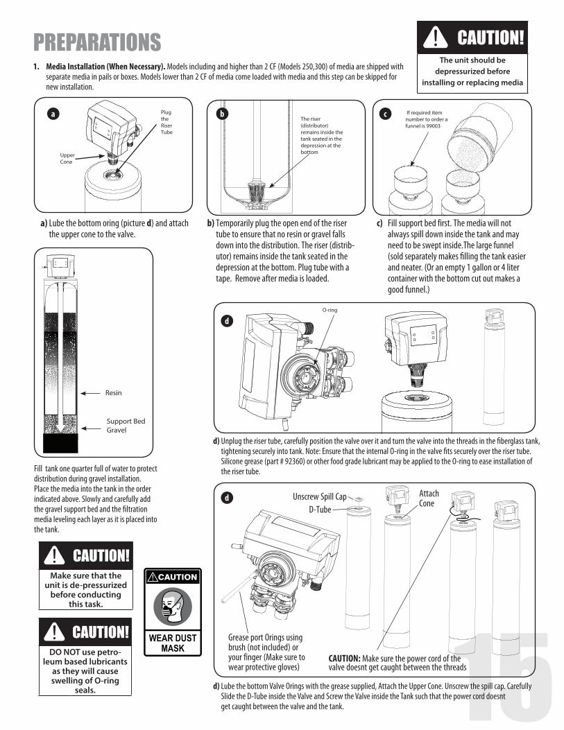
a) Lube the bottom oring (picture d) and attach the upper cone to the valve.
b) Temporarily plug the open end of the riser tube to ensure that no resin or gravel falls down into the distribution. The riser (distrib-utor) remains inside the tank seated in the depression at the bottom. Plug tube with a tape. Remove after media is loaded.
c) Fill support bed first. The media will not always spill down inside the tank and may need to be swept inside.The large funnel (sold separately makes filling the tank easier and neater. (Or an empty 1 gallon or 4 liter container with the bottom cut out makes a good funnel.)
a b cPlugtheRiserTube
Upper Cone
If required item number to order a funnel is 99003
Fill tank one quarter full of water to protect distribution during gravel installation.Place the media into the tank in the order indicated above. Slowly and carefully add the gravel support bed and the filtration media leveling each layer as it is placed into the tank.
d) Unplug the riser tube, carefully position the valve over it and turn the valve into the threads in the fiberglass tank, tightening securely into tank. Note: Ensure that the internal O-ring in the valve fits securely over the riser tube. Silicone grease (part # 92360) or other food grade lubricant may be applied to the O-ring to ease installation of the riser tube.
d) Lube the bottom Valve Orings with the grease supplied, Attach the Upper Cone. Unscrew the spill cap. Carefully Slide the D-Tube inside the Valve and Screw the Valve inside the Tank such that the power cord doesnt get caught between the valve and the tank.
O-ring
d
d
CAUTION: Make sure the power cord of the valve doesnt get caught between the threads
Grease port Orings using brush (not included) or your finger (Make sure to wear protective gloves)
D-TubeUnscrew Spill Cap Attach
Cone
Resin
Support BedGravel
PREPARATIONS1. Media Installation (When Necessary). Models including and higher than 2 CF (Models 250,300) of media are shipped with separate media in pails or boxes. Models lower than 2 CF of media come loaded with media and this step can be skipped for new installation.
CAUTION!The unit should be
depressurized before installing or replacing media
CAUTION!Make sure that the
unit is de-pressurized before conducting
this task.
CAUTION!DO NOT use petro-
leum based lubricants as they will cause swelling of O-ring
seals.
162. Water Lines
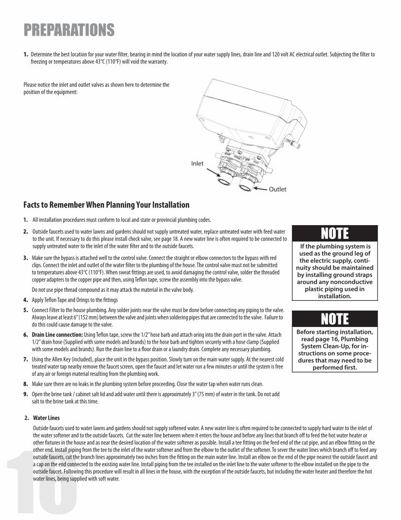
Outside faucets used to water lawns and gardens should not supply softened water. A new water line is often required to be connected to supply hard water to the inlet of the water softener and to the outside faucets. Cut the water line between where it enters the house and before any lines that branch off to feed the hot water heater or other fixtures in the house and as near the desired location of the water softener as possible. Install a tee fitting on the feed end of the cut pipe, and an elbow fitting on the other end. Install piping from the tee to the inlet of the water softener and from the elbow to the outlet of the softener. To sever the water lines which branch off to feed any outside faucets, cut the branch lines approximately two inches from the fitting on the main water line. Install an elbow on the end of the pipe nearest the outside faucet and a cap on the end connected to the existing water line. Install piping from the tee installed on the inlet line to the water softener to the elbow installed on the pipe to the outside faucet. Following this procedure will result in all lines in the house, with the exception of the outside faucets, but including the water heater and therefore the hot water lines, being supplied with soft water.
Inlet
Outlet
NOTE If the plumbing system is used as the ground leg of the electric supply, conti-
nuity should be maintained by installing ground straps around any nonconductive
plastic piping used in installation.
NOTEBefore starting installation,
read page 16, Plumbing System Clean-Up, for in-
structions on some proce-dures that may need to be
performed first.
Facts to Remember When Planning Your Installation
1. All installation procedures must conform to local and state or provincial plumbing codes.
2. Outside faucets used to water lawns and gardens should not supply untreated water, replace untreated water with feed water to the unit. If necessary to do this please install check valve, see page 18. A new water line is often required to be connected to supply untreated water to the inlet of the water filter and to the outside faucets.
3. Make sure the bypass is attached well to the control valve. Connect the straight or elbow connectors to the bypass with red clips. Connect the inlet and outlet of the water filter to the plumbing of the house. The control valve must not be submitted to temperatures above 43°C (110°F). When sweat fittings are used, to avoid damaging the control valve, solder the threaded copper adapters to the copper pipe and then, using Teflon tape, screw the assembly into the bypass valve.
Do not use pipe thread compound as it may attack the material in the valve body.
4. Apply Teflon Tape and Orings to the fittings
5. Connect Filter to the house plumbing. Any solder joints near the valve must be done before connecting any piping to the valve. Always leave at least 6” (152 mm) between the valve and joints when soldering pipes that are connected to the valve. Failure to do this could cause damage to the valve.
6. Drain Line connection: Using Teflon tape, screw the 1/2” hose barb and attach oring into the drain port in the valve. Attach 1/2” drain hose (Supplied with some models and brands) to the hose barb and tighten securely with a hose clamp (Supplied with some models and brands). Run the drain line to a floor drain or a laundry drain. Complete any necessary plumbing.
7. Using the Allen Key (included), place the unit in the bypass position. Slowly turn on the main water supply. At the nearest cold treated water tap nearby remove the faucet screen, open the faucet and let water run a few minutes or until the system is free of any air or foreign material resulting from the plumbing work.
8. Make sure there are no leaks in the plumbing system before proceeding. Close the water tap when water runs clean.
9. Open the brine tank / cabinet salt lid and add water until there is approximately 3” (75 mm) of water in the tank. Do not add salt to the brine tank at this time.
1. Determine the best location for your water filter, bearing in mind the location of your water supply lines, drain line and 120 volt AC electrical outlet. Subjecting the filter to freezing or temperatures above 43°C (110°F) will void the warranty.
PREPARATIONS
Please notice the inlet and outlet valves as shown here to determine the position of the equipment:
16 17
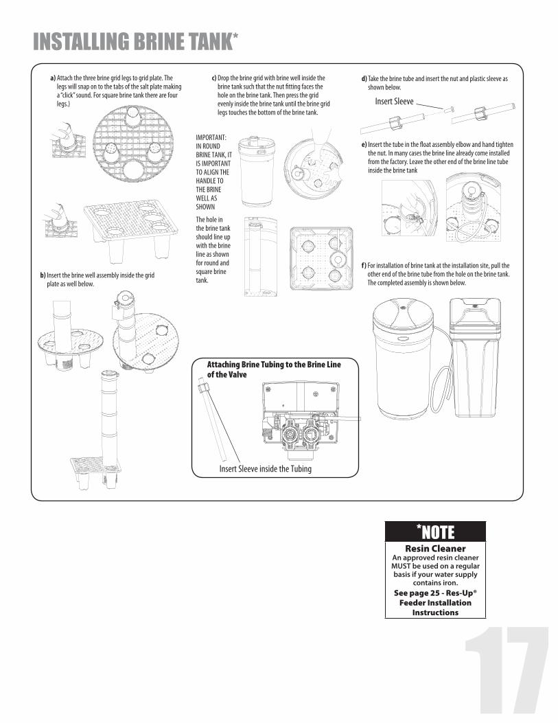
Insert Sleeve inside the Tubing
Attaching Brine Tubing to the Brine Line of the Valve
*NOTEResin Cleaner
An approved resin cleaner MUST be used on a regular basis if your water supply
contains iron.See page 25 - Res-Up®
Feeder Installation Instructions
a) Attach the three brine grid legs to grid plate. The legs will snap on to the tabs of the salt plate making a “click” sound. For square brine tank there are four legs.)
c) Drop the brine grid with brine well inside the brine tank such that the nut fitting faces the hole on the brine tank. Then press the grid evenly inside the brine tank until the brine grid legs touches the bottom of the brine tank.
b) Insert the brine well assembly inside the grid plate as well below.
d) Take the brine tube and insert the nut and plastic sleeve as shown below.
e) Insert the tube in the float assembly elbow and hand tighten the nut. In many cases the brine line already come installed from the factory. Leave the other end of the brine line tube inside the brine tank
f) For installation of brine tank at the installation site, pull the other end of the brine tube from the hole on the brine tank. The completed assembly is shown below.
The hole in the brine tank should line up with the brine line as shown for round and square brine tank.
IMPORTANT: IN ROUND BRINE TANK, IT IS IMPORTANT TO ALIGN THE HANDLE TO THE BRINE WELL AS SHOWN
Insert Sleeve
INSTALLING BRINE TANK*
18
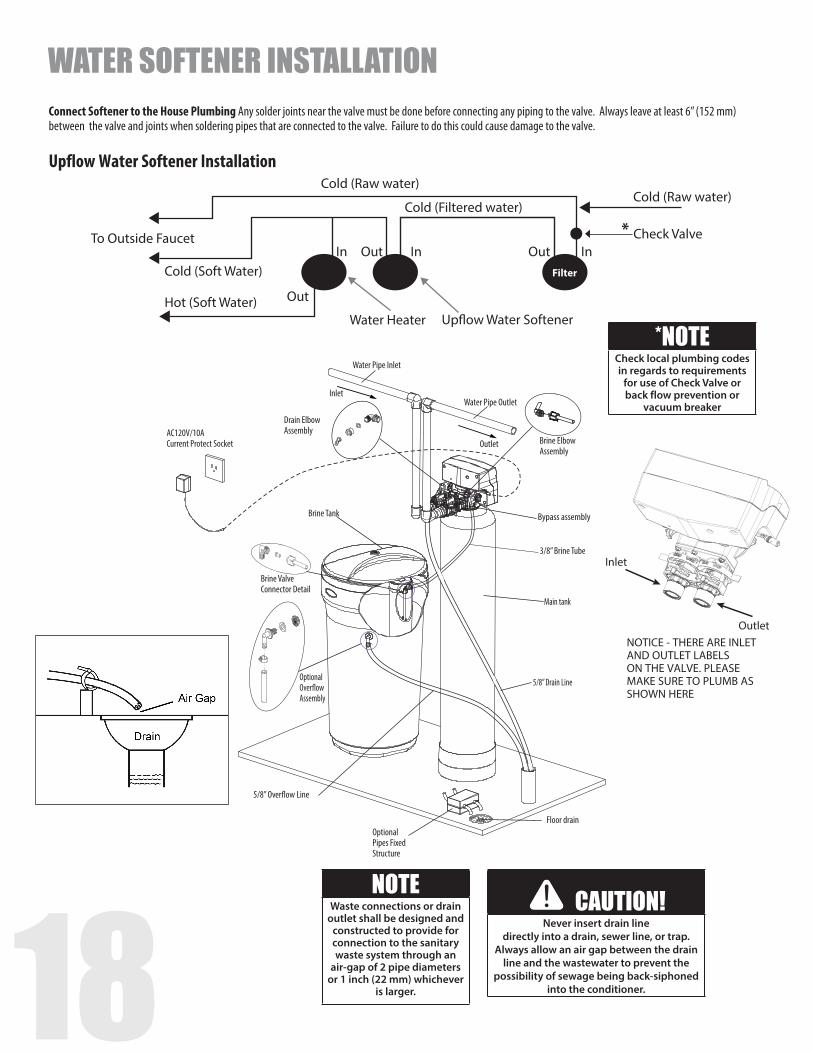
Optional Over�ow Assembly
Brine Valve Connector Detail
AC120V/10ACurrent Protect Socket Brine Elbow
Assembly
Water Pipe Outlet
Main tank
5/8” Drain Line
Bypass assembly
5/8” Over�ow Line
Floor drainOptional Pipes Fixed Structure
Drain Elbow Assembly
Outlet
Brine Tank
3/8” Brine Tube
Inlet
Water Pipe Inlet
Upflow Water Softener Installation
OutletNOTICE - THERE ARE INLET AND OUTLET LABELS ON THE VALVE. PLEASE MAKE SURE TO PLUMB AS SHOWN HERE
Inlet
*NOTECheck local plumbing codes in regards to requirements
for use of Check Valve or back flow prevention or
vacuum breaker
Cold (Raw water)
Cold (Filtered water)Cold (Raw water)
Check Valve
Water HeaterHot (Soft Water)
Up�ow Water Softener
Filter
InIn Out
Out
Cold (Soft Water)
To Outside FaucetInOut
*
CAUTION!Never insert drain line
directly into a drain, sewer line, or trap. Always allow an air gap between the drain
line and the wastewater to prevent the possibility of sewage being back-siphoned
into the conditioner.
NOTEWaste connections or drain
outlet shall be designed and constructed to provide for connection to the sanitary waste system through an
air-gap of 2 pipe diameters or 1 inch (22 mm) whichever
is larger.
Connect Softener to the House Plumbing Any solder joints near the valve must be done before connecting any piping to the valve. Always leave at least 6” (152 mm) between the valve and joints when soldering pipes that are connected to the valve. Failure to do this could cause damage to the valve.
WATER SOFTENER INSTALLATION
18 19
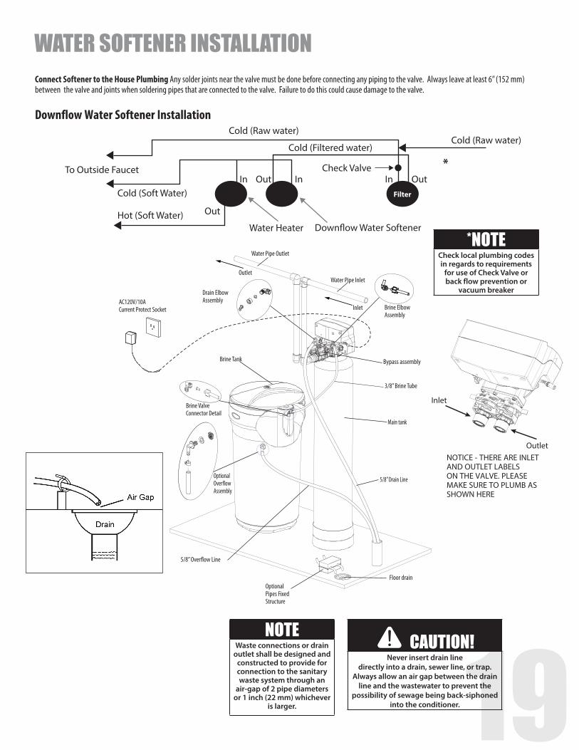
Optional Over�ow Assembly
Brine Valve Connector Detail
AC120V/10ACurrent Protect Socket Brine Elbow
Assembly
Water Pipe Inlet
Main tank
5/8” Drain Line
Bypass assembly
5/8” Over�ow Line
Floor drainOptional Pipes Fixed Structure
Drain Elbow Assembly
Inlet
Brine Tank
3/8” Brine Tube
Outlet
Water Pipe Outlet
Downflow Water Softener Installation
OutletNOTICE - THERE ARE INLET AND OUTLET LABELS ON THE VALVE. PLEASE MAKE SURE TO PLUMB AS SHOWN HERE
Inlet
*NOTECheck local plumbing codes in regards to requirements
for use of Check Valve or back flow prevention or
vacuum breaker
Cold (Raw water)
Cold (Filtered water)Cold (Raw water)
Check Valve
Water HeaterHot (Soft Water)
Down�ow Water Softener
Filter
In In Out
Out
Cold (Soft Water)
To Outside FaucetOut In
*
CAUTION!Never insert drain line
directly into a drain, sewer line, or trap. Always allow an air gap between the drain
line and the wastewater to prevent the possibility of sewage being back-siphoned
into the conditioner.
NOTEWaste connections or drain
outlet shall be designed and constructed to provide for connection to the sanitary waste system through an
air-gap of 2 pipe diameters or 1 inch (22 mm) whichever
is larger.
Connect Softener to the House Plumbing Any solder joints near the valve must be done before connecting any piping to the valve. Always leave at least 6” (152 mm) between the valve and joints when soldering pipes that are connected to the valve. Failure to do this could cause damage to the valve.
WATER SOFTENER INSTALLATION
20
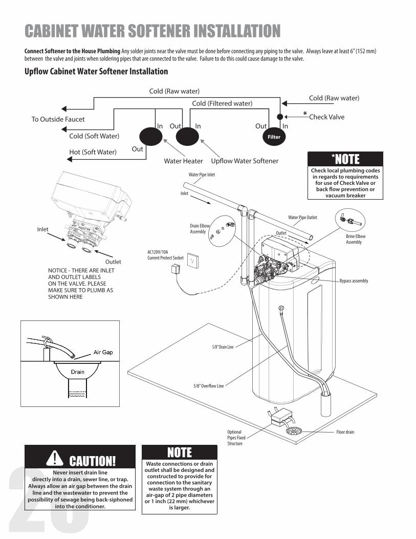
Upflow Cabinet Water Softener Installation
Brine Elbow Assembly
Water Pipe Outlet
Bypass assembly
Outlet
Inlet
Water Pipe Inlet
Drain Elbow Assembly
Floor drainOptional Pipes Fixed Structure
5/8” Over�ow Line
AC120V/10ACurrent Protect Socket
5/8” Drain Line
OutletNOTICE - THERE ARE INLET AND OUTLET LABELS ON THE VALVE. PLEASE MAKE SURE TO PLUMB AS SHOWN HERE
Inlet
CAUTION!Never insert drain line
directly into a drain, sewer line, or trap. Always allow an air gap between the drain
line and the wastewater to prevent the possibility of sewage being back-siphoned
into the conditioner.
NOTEWaste connections or drain
outlet shall be designed and constructed to provide for connection to the sanitary waste system through an
air-gap of 2 pipe diameters or 1 inch (22 mm) whichever
is larger.
*NOTECheck local plumbing codes in regards to requirements
for use of Check Valve or back flow prevention or
vacuum breaker
Cold (Raw water)
Cold (Filtered water)Cold (Raw water)
Check Valve
Water HeaterHot (Soft Water)
Up�ow Water Softener
Filter
InIn Out
Out
Cold (Soft Water)
To Outside FaucetInOut
*
CABINET WATER SOFTENER INSTALLATIONConnect Softener to the House Plumbing Any solder joints near the valve must be done before connecting any piping to the valve. Always leave at least 6” (152 mm) between the valve and joints when soldering pipes that are connected to the valve. Failure to do this could cause damage to the valve.

20 21
Downflow Cabinet Water Softener Installation
Brine Elbow Assembly
Brine Line
Water Pipe Inlet
Bypass assembly
Inlet
Outlet
Water Pipe Outlet
Drain Elbow Assembly
Floor drainOptional Pipes Fixed Structure
5/8” Over�ow Line
AC120V/10ACurrent Protect Socket
5/8” Drain Line
OutletNOTICE - THERE ARE INLET AND OUTLET LABELS ON THE VALVE. PLEASE MAKE SURE TO PLUMB AS SHOWN HERE
Inlet
CAUTION!Never insert drain line
directly into a drain, sewer line, or trap. Always allow an air gap between the drain
line and the wastewater to prevent the possibility of sewage being back-siphoned
into the conditioner.
NOTEWaste connections or drain
outlet shall be designed and constructed to provide for connection to the sanitary waste system through an
air-gap of 2 pipe diameters or 1 inch (22 mm) whichever
is larger.
*NOTECheck local plumbing codes in regards to requirements
for use of Check Valve or back flow prevention or
vacuum breaker
CABINET WATER SOFTENER INSTALLATION
Cold (Raw water)
Cold (Filtered water)Cold (Raw water)
Check Valve
Water HeaterHot (Soft Water)
Down�ow Water Softener
Filter
In In Out
Out
Cold (Soft Water)
To Outside FaucetOut In
*
Connect Softener to the House Plumbing Any solder joints near the valve must be done before connecting any piping to the valve. Always leave at least 6” (152 mm) between the valve and joints when soldering pipes that are connected to the valve. Failure to do this could cause damage to the valve.
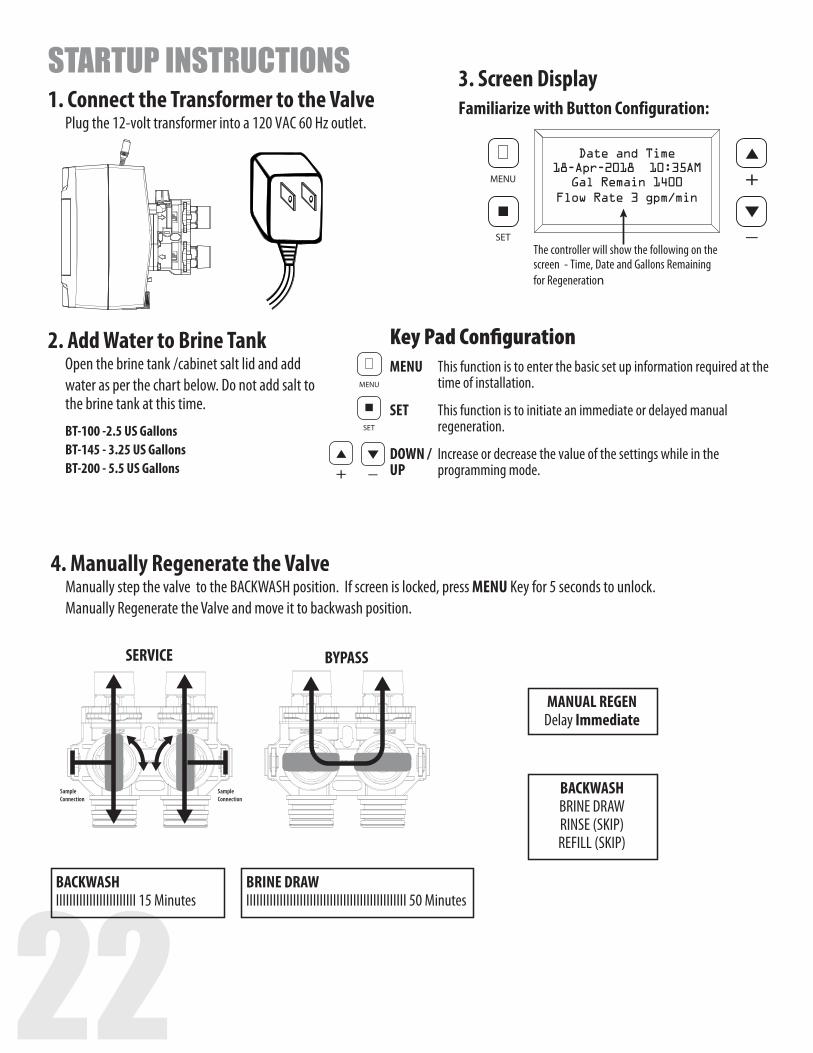
22
STARTUP INSTRUCTIONS1. Connect the Transformer to the Valve Plug the 12-volt transformer into a 120 VAC 60 Hz outlet.
2. Add Water to Brine Tank Open the brine tank /cabinet salt lid and add
water as per the chart below. Do not add salt to the brine tank at this time.
BT-100 -2.5 US Gallons BT-145 - 3.25 US Gallons BT-200 - 5.5 US Gallons
Familiarize with Button Configuration:3. Screen Display
MENU SET
MENU SET
MENU SET
Key Pad ConfigurationMENU This function is to enter the basic set up information required at the time of installation.
SET This function is to initiate an immediate or delayed manual regeneration.
DOWN / Increase or decrease the value of the settings while in the UP programming mode.
MENU
SET
Date and Time18-Apr-2018 10:35AM
Gal Remain 1400Flow Rate 3 gpm/min
The controller will show the following on the screen - Time, Date and Gallons Remaining for Regeneration
4. Manually Regenerate the Valve Manually step the valve to the BACKWASH position. If screen is locked, press MENU Key for 5 seconds to unlock. Manually Regenerate the Valve and move it to backwash position.
SampleConnection
SampleConnection
SERVICE
BYPASS
SampleConnection
SampleConnection
SERVICE
BYPASS
MANUAL REGENDelay Immediate
BACKWASHIIIIIIIIIIIIIIIIIIIIIIII 15 Minutes
BRINE DRAWIIIIIIIIIIIIIIIIIIIIIIIIIIIIIIIIIIIIIIIIIIIIIIII 50 Minutes
BACKWASHBRINE DRAWRINSE (SKIP)REFILL (SKIP)
22 23
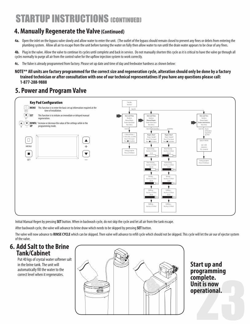
4. Manually Regenerate the Valve (Continued)4a. Open the inlet on the bypass valve slowly and allow water to enter the unit. (The outlet of the bypass should remain closed to prevent any fines or debris from entering the plumbing system. Allow all air to escape from the unit before turning the water on fully then allow water to run until the drain water appears to be clear of any fines.
4b. Plug in the valve. Allow the valve to continue its cycles until complete and back in service. Do not manually shorten this cycle as it is critical to have the valve go through all cycles normally to purge all air from the control valve for the upflow injection system to work correctly.
4c. The Valve is already programmed from factory. Please set up date and time of day and feedwater hardness as shown below:
NOTE** All units are factory programmed for the correct size and regeneration cycle, alteration should only be done by a factory trained technician or after consultation with one of our technical representatives if you have any questions please call: 1-877-288-9888
STARTUP INSTRUCTIONS (CONTINUED)
5. Power and Program Valve
Initial Manual Regen by pressing SET button. When in backwash cycle, do not skip the cycle and let all air from the tank escape.
After backwash cycle, the valve will advance to brine draw which needs to be skipped by pressing SET button.
The valve will now advance to RINSE CYCLE which can be skipped. Then valve will advance to refill cycle which should not be skipped. This cycle will let the air our of ejector system of the valve.
6. Add Salt to the Brine Tank/Cabinet Put 40 kgs of crystal water softener salt in the brine tank. The unit will automatically fill the water to the correct level when it regenerates.
Start up and programming complete. Unit is now operational.
MENU SET
MENU SET
MENU SET
Key Pad ConfigurationMENU This function is to enter the basic set up information required at the time of installation.
SET This function is to initiate an immediate or delayed manual regeneration.
DOWN / Increase or decrease the value of the settings while in the UP programming mode.
MENU
SET
Date and TimeHardness
Manual Regen.Dealer Information
Main Menu
Regen. Now?Regen. Tonight?
Press To CancelPress To Con�rm
Backwashing ...Any Key 3s To Next
13:59
89 Down�ow 89 Up�owAuto On
18%
Brine Drawing ...Any Key 3s To Next
063:5950%
Rinsing ...Any Key 3s To Next
00:0090%
Re�lling ...Any Key 3s To Next
00:0098%
Re�lling ...Any Key 3s To Next
Regen. Now?Regen. Tonight?
Press To CancelPress To Con�rm
Brine Drawing ...Any Key 3s To Next
103:5968%
Backwashing ...Any Key 3s To Next
13:5988%
Rinsing ...Any Key 3s To Next
12:0990%
Re�lling ...Any Key 3s To Next
03:5998%
Re�lling ...Any Key 3s To Next
Date and TimeHardness
Manual Regen.Dealer Information
Main Menu
QUALITY WATER
666 3 AVECHIGAGO IL
TEL 12345678
Setting CompletePress To Return
Date and TimeHardness
Manual Regen.Dealer Information
Main Menu
= Date and Time =17-Feb-2016, 12:25PM
Press To CancelPress To Con�rm
Setting CompletePress To Return
Standby interface
Auto On
Auto On
Auto On Dealer informationinput letter by letter
24
SampleConnection
SampleConnection
SERVICE
BYPASS
SampleConnection
SampleConnection
SERVICE
BYPASS
BYPASS
DURING REGENERATIONAutomatic Water BypassThe regeneration cycle lasts approximately 1.5 hours to 3.0 hours depending on the specific model, after which treated water service will be restored. During regeneration, untreated water is automatically bypassed for use in the household. Hot water should be used as little as possible during this time to prevent hard water from filling the water heater.
IMPORTANT: This is why the automatic regeneration is set for sometime during the night and manual regenerations should be performed when little or no water will be used in the household.
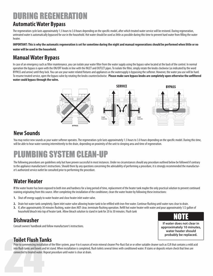
Manual Water BypassIn case of an emergency such as filter maintenance, you can isolate your water filter from the water supply using the bypass valve located at the back of the control. In normal operation the bypass is open with the ON/OFF knobs in line with the INLET and OUTLET pipes. To isolate the filter, simply rotate the knobs clockwise (as indicated by the word BYPASS and arrow) until they lock. You can use your water related fixtures and appliances as the watersupply is bypassing the softener. However, the water you use will be hard. To resume treated service, open the bypass valve by rotating the knobs counterclockwise. Please make sure bypass knobs are completely open otherwise the unfiltered water could bypass through the valve.
New SoundsYou may notice new sounds as your water softener operates. The regeneration cycle lasts approximately 1.5 hours to 3.0 hours depending on the specific model. During this time, will be able to hear water running intermittently to the drain, depending on proximity of the unit to sleeping area and time of regeneration.
PLUMBING SYSTEM CLEAN-UPThe following procedures are guidelines only but have proven successful in most instances. Under no circumstances should any procedure outlined below be followed if contrary to the appliance manufacturer’s instructions. Should there by any questions concerning the advisability of performing a procedure, it is strongly recommended the manufactur-er’s authorized service outlet be consulted prior to performing the procedure.
Water HeaterIf the water heater has been exposed to both iron and hardness for a long period of time, replacement of the heater tank maybe the only practical solution to prevent continued staining originating from this source. After completing the installation of the conditioner, clean the water heater by following these instructions:
1. Shut off energy supply to water heater and close heater inlet water valve.
2. Drain hot water tank completely. Open inlet water valve allowing heater tank to be refilled with iron-free water. Continue flushing until water runs clear to drain.3. If, after approximately 30 minutes flushing, water does NOT clear, terminate flushing operation. Refill hot water heater with water and pour approximately 1/2 gallon of household bleach into top of heater tank. Allow bleach solution to stand in tank for 20 to 30 minutes. Flush tank
DishwasherConsult owners’ handbook and follow manufacturer’s instructions.
Toilet Flush TanksPrior to commencing installation of the filter system, pour 4 to 6 ounces of resin mineral cleaner Pro-Rust Out or or other suitable cleaner such as CLR that contains a mild acid into flush tanks and bowls and let stand. When installation is completed, flush toilets several times with conditioned water. If stains or deposits return check that lines are connected to treated water. Repeat procedure until water is clear at drain.
NOTEIf water does not clear in
approximately 10 minutes, water heater should
probably be replaced.
24 25
Service Schedule � The seals and spacers along with the piston assembly should be inspected/cleaned or replaced every year depending on the inlet water quality and water usage. See inspection and replacement of Piston assembly and seal and spacer kit, page 28.
� The injectors should be cleaned/inspected or replaced every year depending on the water quality and use. See Clean Injector Assembly, page 29.
� Maintenance Kit (60010564) should be used for servicing control on an annual basis. The maintenance kit consists of piston assembly, seals and spacers, injectors.
Maintenance of your new water conditioner requires very little time or effort but it is essential. Regular maintenance will ensure many years of efficient and trouble free operation.
FAILURE TO FOLLOW BASIC MAINTENANCE SCHEDULE WILL RESULT IN THE UNIT FAILING TO OPERATE PROPERLY AND VOID YOUR WARRANTY.
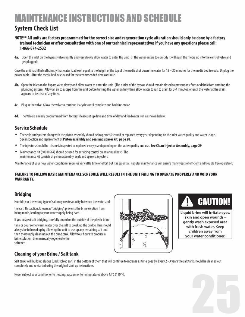
CAUTION!Liquid brine will irritate eyes,
skin and open wounds -gently wash exposed area
with fresh water. Keep children away from
your water conditioner.
BridgingHumidity or the wrong type of salt may create a cavity between the water and
the salt. This action, known as “bridging”, prevents the brine solution from being made, leading to your water supply being hard.
If you suspect salt bridging, carefully pound on the outside of the plastic brine tank or pour some warm water over the salt to break up the bridge. This should always be followed up by allowing the unit to use up any remaining salt and then thoroughly cleaning out the brine tank. Allow four hours to produce a brine solution, then manually regenerate thesoftener.
Cleaning of your Brine / Salt tankSalt tanks will build up sludge (undissolved salt) in the bottom of them that will continue to increase as time goes by. Every 2 - 3 years the salt tank should be cleaned out completely and re started using the original start up instructions.
Never subject your conditioner to freezing, vacuum or to temperatures above 43°C (110°F).
MAINTENANCE INSTRUCTIONS AND SCHEDULESystem Check ListNOTE** All units are factory programmed for the correct size and regeneration cycle alteration should only be done by a factory
trained technician or after consultation with one of our technical representatives if you have any questions please call: 1-866-874-2532
4a. Open the inlet on the bypass valve slightly and very slowly allow water to enter the unit. (If the water enters too quickly it will push the media up into the control valve and get plugged).
Once the unit has filled sufficiently that water is at least equal to the height of the top of the media shut down the water for 15 – 20 minutes for the media bed to soak. Unplug the power cable. After the media bed has soaked for the recommended time continue. 4b. Open the inlet on the bypass valve slowly and allow water to enter the unit. (The outlet of the bypass should remain closed to prevent any fines or debris from entering the plumbing system. Allow all air to escape from the unit before turning the water on fully then allow water to run to drain for 3-4 minutes, or until the water at the drain appears to be clear of any fines.
4c. Plug in the valve. Allow the valve to continue its cycles until complete and back in service
4d. The Valve is already programmed from factory. Please set up date and time of day and feedwater iron as shown below:
26
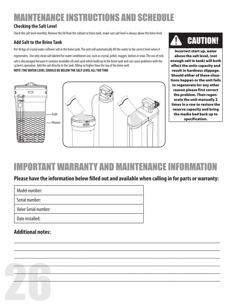
Salt
Water
Checking the Salt LevelCheck the salt level monthly. Remove the lid from the cabinet or brine tank, make sure salt level is always above the brine level. Add Salt to the Brine TankPut 40 kgs of crystal water softener salt in the brine tank. The unit will automatically fill the water to the correct level when it
regenerates. Use only clean salt labeled for water conditioner use, such as crystal, pellet, nugget, button or solar. The use of rock salt is discouraged because it contains insoluble silt and sand which build up in the brine tank and can cause problems with the system’s operation. Add the salt directly to the tank, filling no higher than the top of the brine well. NOTE :THE WATER LEVEL SHOULD BE BELOW THE SALT LEVEL ALL THE TIME
CAUTION!Incorrect start up, water above the salt level, (not
enough salt in tank) will both effect the units capacity and result in hardness slippage. Should either of these situa-tions happen or the unit fails
to regenerate for any other reason please first correct the problem. Then regen-erate the unit manually 2
times in a row to restore the reserve capacity and bring the media bed back up to
specification.
IMPORTANT WARRANTY AND MAINTENANCE INFORMATION
Model number:
Serial number:
Valve Serial number:
Date installed:
Please have the information below filled out and available when calling in for parts or warranty:
Additional notes:__________________________________________________________________________________________________________________________________________________________________________________________________________________________________________________________________________________________________________________________________________________________________________________________________________________
MAINTENANCE INSTRUCTIONS AND SCHEDULE
26 27
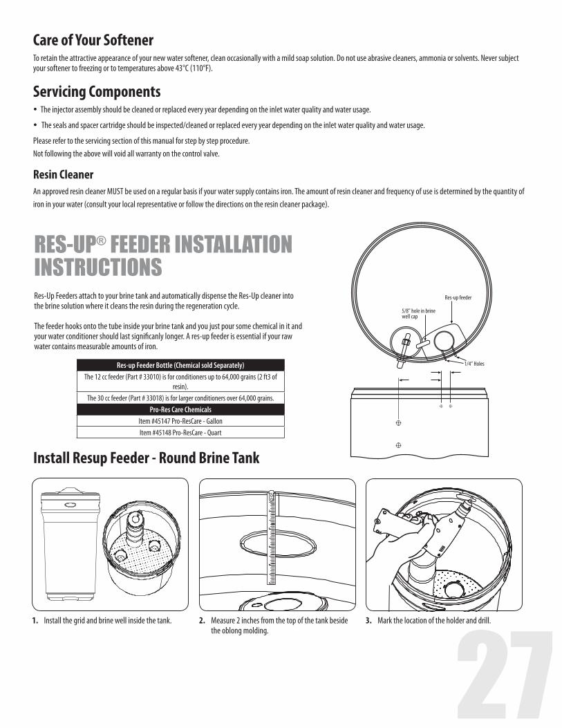
5/8" hole in brinewell cap
Res-up feeder
1/4” Holes Res-up Feeder Bottle (Chemical sold Separately)The 12 cc feeder (Part # 33010) is for conditioners up to 64,000 grains (2 ft3 of
resin).The 30 cc feeder (Part # 33018) is for larger conditioners over 64,000 grains.
Pro-Res Care ChemicalsItem #45147 Pro-ResCare - GallonItem #45148 Pro-ResCare - Quart
1. Install the grid and brine well inside the tank. 3. Mark the location of the holder and drill.2. Measure 2 inches from the top of the tank beside the oblong molding.
RES-UP® FEEDER INSTALLATION INSTRUCTIONS Res-Up Feeders attach to your brine tank and automatically dispense the Res-Up cleaner into the brine solution where it cleans the resin during the regeneration cycle. The feeder hooks onto the tube inside your brine tank and you just pour some chemical in it and your water conditioner should last significanly longer. A res-up feeder is essential if your raw water contains measurable amounts of iron.
Install Resup Feeder - Round Brine Tank
Care of Your SoftenerTo retain the attractive appearance of your new water softener, clean occasionally with a mild soap solution. Do not use abrasive cleaners, ammonia or solvents. Never subject your softener to freezing or to temperatures above 43°C (110°F). Servicing Components�The injector assembly should be cleaned or replaced every year depending on the inlet water quality and water usage.
�The seals and spacer cartridge should be inspected/cleaned or replaced every year depending on the inlet water quality and water usage.
Please refer to the servicing section of this manual for step by step procedure.Not following the above will void all warranty on the control valve.
Resin CleanerAn approved resin cleaner MUST be used on a regular basis if your water supply contains iron. The amount of resin cleaner and frequency of use is determined by the quantity of iron in your water (consult your local representative or follow the directions on the resin cleaner package).
28
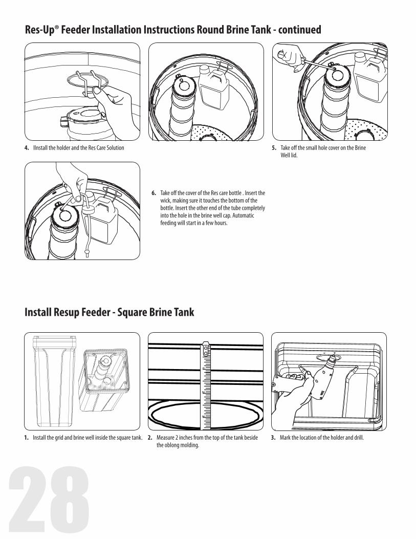
4. IInstall the holder and the Res Care Solution 5. Take off the small hole cover on the Brine Well lid.
6. Take off the cover of the Res care bottle . Insert the wick, making sure it touches the bottom of the bottle. Insert the other end of the tube completely into the hole in the brine well cap. Automatic feeding will start in a few hours.
Res-Up® Feeder Installation Instructions Round Brine Tank - continued
1. Install the grid and brine well inside the square tank. 3. Mark the location of the holder and drill.2. Measure 2 inches from the top of the tank beside the oblong molding.
Install Resup Feeder - Square Brine Tank
28 29
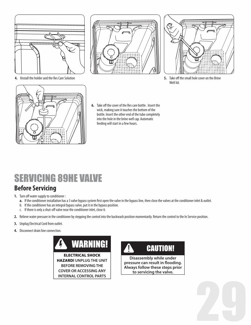
4. IInstall the holder and the Res Care Solution 5. Take off the small hole cover on the Brine Well lid.
6. Take off the cover of the Res care bottle . Insert the wick, making sure it touches the bottom of the bottle. Insert the other end of the tube completely into the hole in the brine well cap. Automatic feeding will start in a few hours.
Before Servicing1. Turn off water supply to conditioner : a. If the conditioner installation has a 3 valve bypass system first open the valve in the bypass line, then close the valves at the conditioner inlet & outlet. b. If the conditioner has an integral bypass valve, put it in the bypass position. c. If there is only a shut-off valve near the conditioner inlet, close it.
2. Relieve water pressure in the conditioner by stepping the control into the backwash position momentarily. Return the control to the In Service position.
3. Unplug Electrical Cord from outlet.
4. Disconnect drain line connection.
SERVICING 89HE VALVE
CAUTION!Disassembly while under
pressure can result in flooding. Always follow these steps prior
to servicing the valve.
WARNING!ELECTRICAL SHOCK
HAZARD! UNPLUG THE UNIT BEFORE REMOVING THE
COVER OR ACCESSING ANY INTERNAL CONTROL PARTS
30
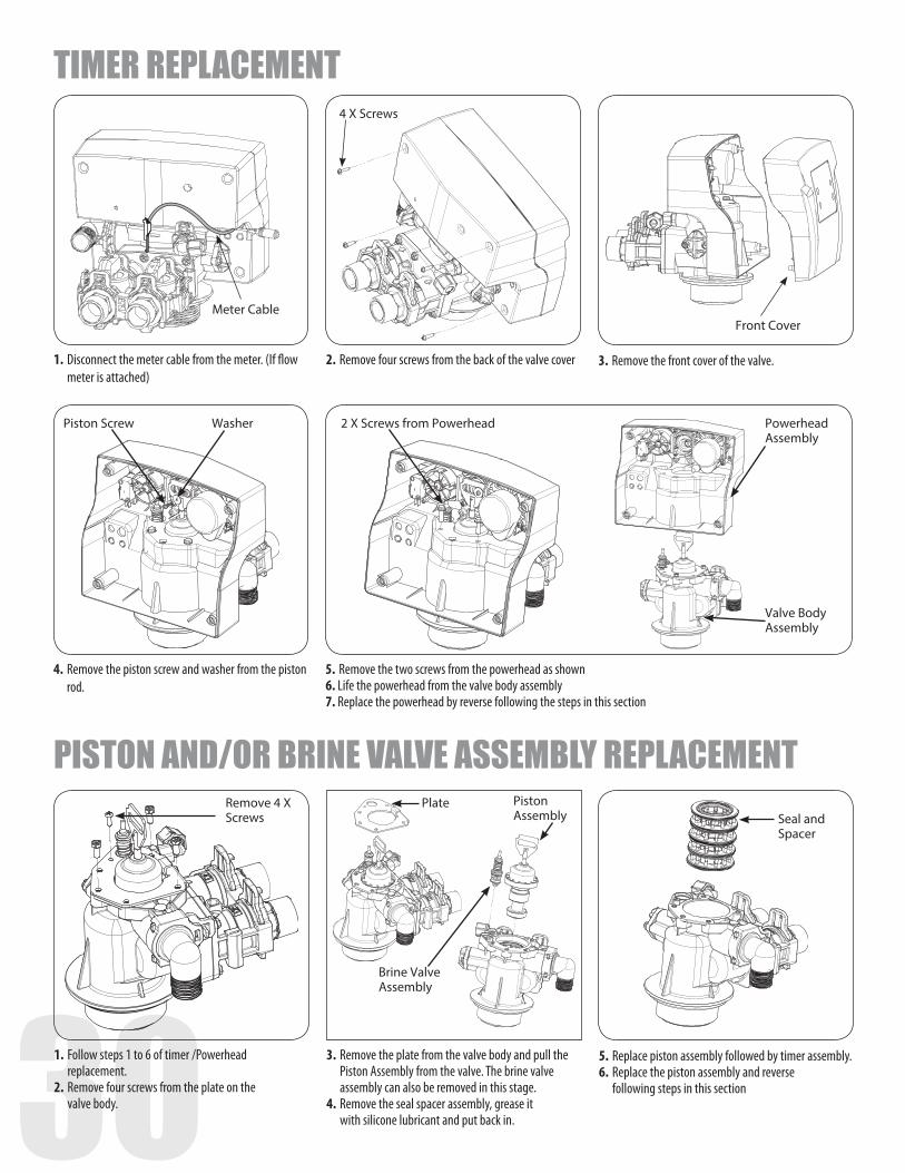
Meter Cable
4 X Screws
Front Cover
1. Disconnect the meter cable from the meter. (If flow meter is attached)
2. Remove four screws from the back of the valve cover 3. Remove the front cover of the valve.
4. Remove the piston screw and washer from the piston rod.
5. Remove the two screws from the powerhead as shown6. Life the powerhead from the valve body assembly7. Replace the powerhead by reverse following the steps in this section
Piston Screw 2 X Screws from PowerheadWasher Powerhead Assembly
Valve Body Assembly
1. Follow steps 1 to 6 of timer /Powerhead replacement.
2. Remove four screws from the plate on the valve body.
3. Remove the plate from the valve body and pull the Piston Assembly from the valve. The brine valve assembly can also be removed in this stage.
4. Remove the seal spacer assembly, grease it with silicone lubricant and put back in.
5. Replace piston assembly followed by timer assembly.6. Replace the piston assembly and reverse
following steps in this section
Remove 4 X Screws
PlateSeal and Spacer
Brine Valve Assembly
Piston Assembly
TIMER REPLACEMENT
PISTON AND/OR BRINE VALVE ASSEMBLY REPLACEMENT
30 31
Meter Cable
2X Clips
3.
2.
4.
5.
1.
Special Tool
Impeller
Remove 6X screws
Meter Support
Meter Cable
1.
2.
3.
4.
5.
2X Clips
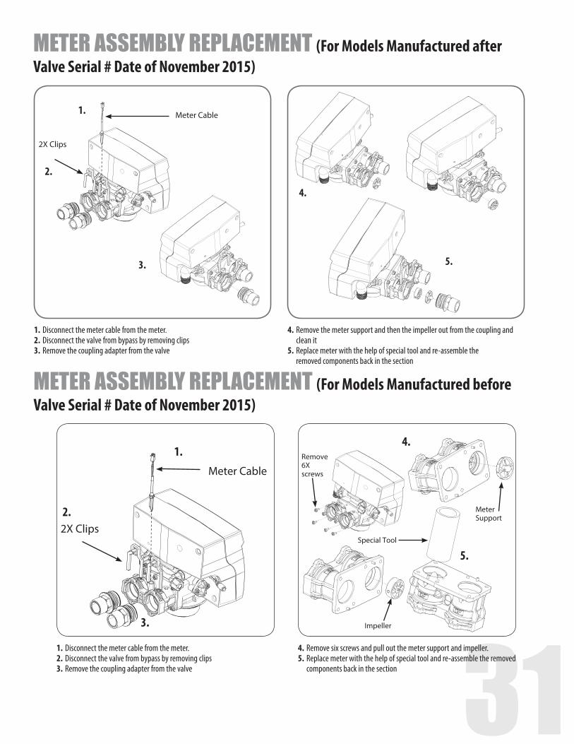
METER ASSEMBLY REPLACEMENT (For Models Manufactured after Valve Serial # Date of November 2015)
1. Disconnect the meter cable from the meter.2. Disconnect the valve from bypass by removing clips3. Remove the coupling adapter from the valve
4. Remove the meter support and then the impeller out from the coupling and clean it
5. Replace meter with the help of special tool and re-assemble the removed components back in the section
METER ASSEMBLY REPLACEMENT (For Models Manufactured before Valve Serial # Date of November 2015)
1. Disconnect the meter cable from the meter.2. Disconnect the valve from bypass by removing clips3. Remove the coupling adapter from the valve
4. Remove six screws and pull out the meter support and impeller.5. Replace meter with the help of special tool and re-assemble the removed components back in the section
32
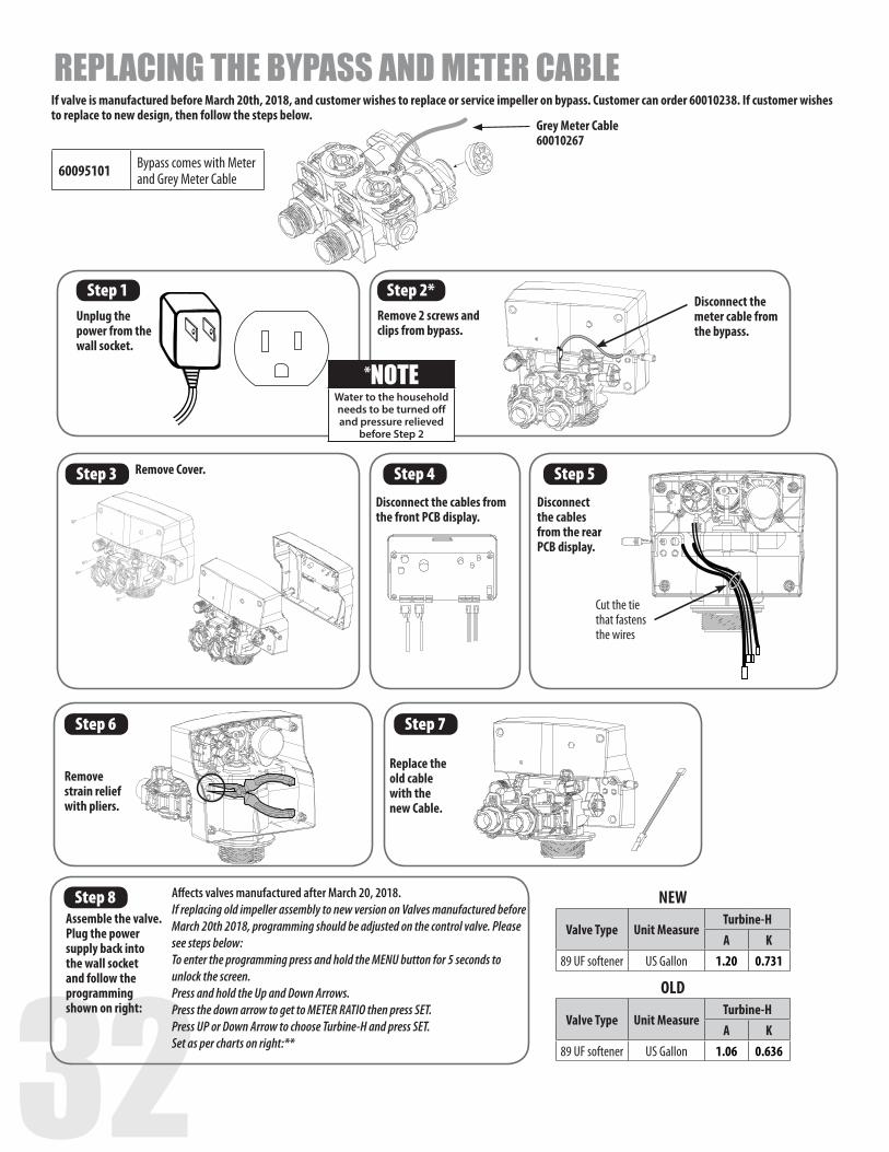
Step 1 Step 2*Unplug the power from the wall socket.
Remove 2 screws and clips from bypass.
Disconnect the meter cable from the bypass.
Grey Meter Cable 60010267
Step 3 Remove Cover. Step 4 Step 5
Step 6 Step 7
Disconnect the cables from the front PCB display.
Disconnect the cables from the rear PCB display.
Remove strain relief with pliers.
Replace the old cable with the new Cable.
60095101 Bypass comes with Meterand Grey Meter Cable
*NOTEWater to the household needs to be turned off and pressure relieved
before Step 2
Affects valves manufactured after March 20, 2018. If replacing old impeller assembly to new version on Valves manufactured before March 20th 2018, programming should be adjusted on the control valve. Please see steps below:To enter the programming press and hold the MENU button for 5 seconds to unlock the screen.Press and hold the Up and Down Arrows.Press the down arrow to get to METER RATIO then press SET.Press UP or Down Arrow to choose Turbine-H and press SET.Set as per charts on right:**
Step 8Assemble the valve. Plug the power supply back into the wall socket and follow the programming shown on right:
Cut the tie that fastens the wires
If valve is manufactured before March 20th, 2018, and customer wishes to replace or service impeller on bypass. Customer can order 60010238. If customer wishes to replace to new design, then follow the steps below.
REPLACING THE BYPASS AND METER CABLE
NEW
Valve Type Unit MeasureTurbine-HA K
89 UF softener US Gallon 1.20 0.731
OLD
Valve Type Unit MeasureTurbine-HA K
89 UF softener US Gallon 1.06 0.636
32 33
2. 1.
4X Screws
4. 2 X Motor Screws
3.
Wire connection to Circuit Board
Circuit Board
1.
3.
2.
4.
Cover 4X Screws
Microswitch
MicroswitchScrews
Front Cover
Wire connections to Circuit Board
REPLACE MICROSWITCHES
Screen
1.
3.
5.
2.
4.
2X ScrewsGasket
Injector Cap
Injector Assembly
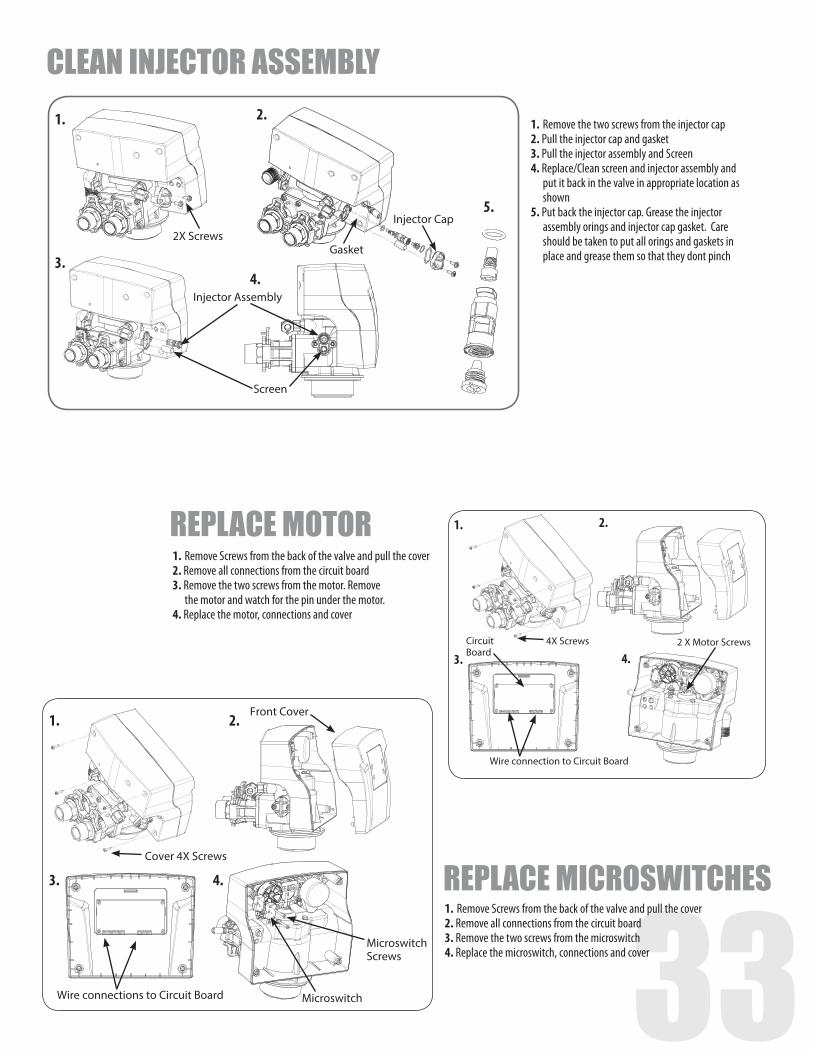
REPLACE MOTOR1. Remove Screws from the back of the valve and pull the cover2. Remove all connections from the circuit board3. Remove the two screws from the motor. Remove the motor and watch for the pin under the motor.4. Replace the motor, connections and cover
1. Remove Screws from the back of the valve and pull the cover2. Remove all connections from the circuit board3. Remove the two screws from the microswitch4. Replace the microswitch, connections and cover
CLEAN INJECTOR ASSEMBLY1. Remove the two screws from the injector cap2. Pull the injector cap and gasket3. Pull the injector assembly and Screen4. Replace/Clean screen and injector assembly and put it back in the valve in appropriate location as shown5. Put back the injector cap. Grease the injector assembly orings and injector cap gasket. Care should be taken to put all orings and gaskets in place and grease them so that they dont pinch
34
Clip
Brine Line Elbow Brine Line Washer
Clip
Drain washer
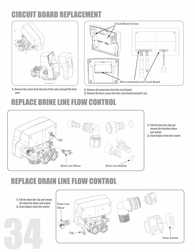
CIRCUIT BOARD REPLACEMENT
Wire connections to Circuit Board
Circuit Board Screws
1. Remove the screws from the back of the valve and pull the front cover
2. Remove all connections from the circuit board3. Remove the fours screws from the circuit board and pull it out
REPLACE BRINE LINE FLOW CONTROL
1. Pull the brine line clip and remove the brineline elbow and washer2. Clean/replace brine line washer
REPLACE DRAIN LINE FLOW CONTROL
Drain Line Elbow
1. Pull the drain line clip and remove the drain line elbow and washer2. Clean/replace drain line washer
34 35
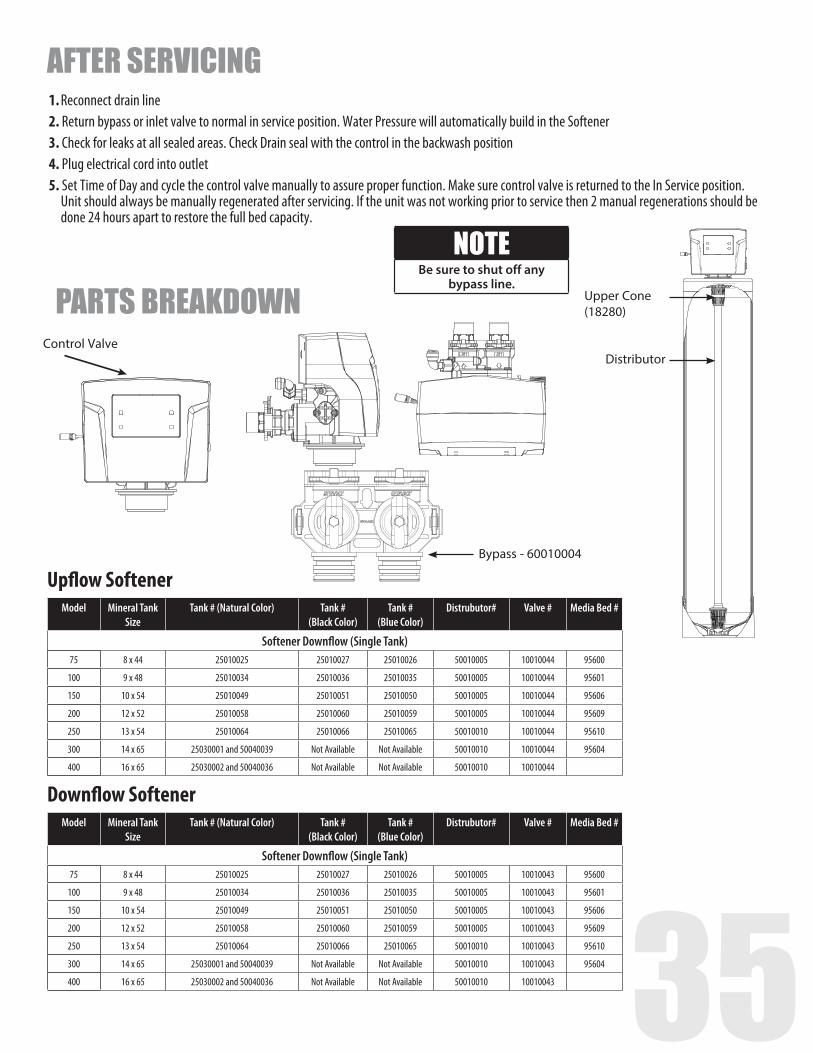
Control ValveDistributor
Upper Cone (18280)
Bypass - 60010004
Model Mineral Tank Size
Tank # (Natural Color) Tank # (Black Color)
Tank # (Blue Color)
Distrubutor# Valve # Media Bed #
Softener Downflow (Single Tank)75 8 x 44 25010025 25010027 25010026 50010005 10010044 95600
100 9 x 48 25010034 25010036 25010035 50010005 10010044 95601
150 10 x 54 25010049 25010051 25010050 50010005 10010044 95606
200 12 x 52 25010058 25010060 25010059 50010005 10010044 95609
250 13 x 54 25010064 25010066 25010065 50010010 10010044 95610
300 14 x 65 25030001 and 50040039 Not Available Not Available 50010010 10010044 95604
400 16 x 65 25030002 and 50040036 Not Available Not Available 50010010 10010044
Upflow Softener
Model Mineral Tank Size
Tank # (Natural Color) Tank # (Black Color)
Tank # (Blue Color)
Distrubutor# Valve # Media Bed #
Softener Downflow (Single Tank)75 8 x 44 25010025 25010027 25010026 50010005 10010043 95600
100 9 x 48 25010034 25010036 25010035 50010005 10010043 95601
150 10 x 54 25010049 25010051 25010050 50010005 10010043 95606
200 12 x 52 25010058 25010060 25010059 50010005 10010043 95609
250 13 x 54 25010064 25010066 25010065 50010010 10010043 95610
300 14 x 65 25030001 and 50040039 Not Available Not Available 50010010 10010043 95604
400 16 x 65 25030002 and 50040036 Not Available Not Available 50010010 10010043
Downflow Softener
AFTER SERVICING1. Reconnect drain line2. Return bypass or inlet valve to normal in service position. Water Pressure will automatically build in the Softener3. Check for leaks at all sealed areas. Check Drain seal with the control in the backwash position4. Plug electrical cord into outlet5. Set Time of Day and cycle the control valve manually to assure proper function. Make sure control valve is returned to the In Service position. Unit should always be manually regenerated after servicing. If the unit was not working prior to service then 2 manual regenerations should be done 24 hours apart to restore the full bed capacity.
NOTEBe sure to shut off any
bypass line.
PARTS BREAKDOWN
36
PARTS BREAKDOWN
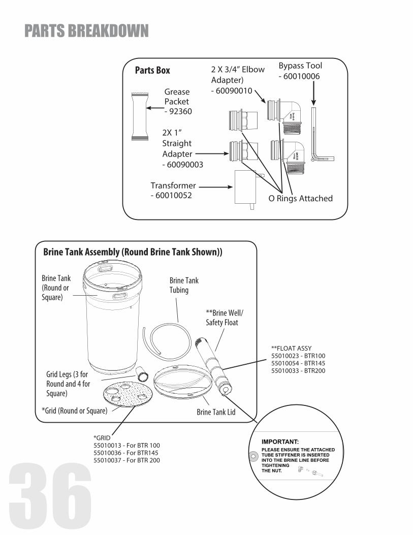
Brine Tank (Round or Square)
Brine Tank Tubing
**Brine Well/Safety Float
Brine Tank Lid*Grid (Round or Square)
Grid Legs (3 for Round and 4 for Square)
Brine Tank Assembly (Round Brine Tank Shown))
*GRID55010013 - For BTR 10055010036 - For BTR14555010037 - For BTR 200
**FLOAT ASSY55010023 - BTR10055010054 - BTR14555010033 - BTR200
Parts Box
2X 1” Straight Adapter- 60090003
Bypass Tool - 60010006
O Rings Attached
2 X 3/4” Elbow Adapter)- 60090010
Transformer- 60010052
Grease Packet- 92360
36 377
8
6
11
1
2
9
5
10
3
4
12
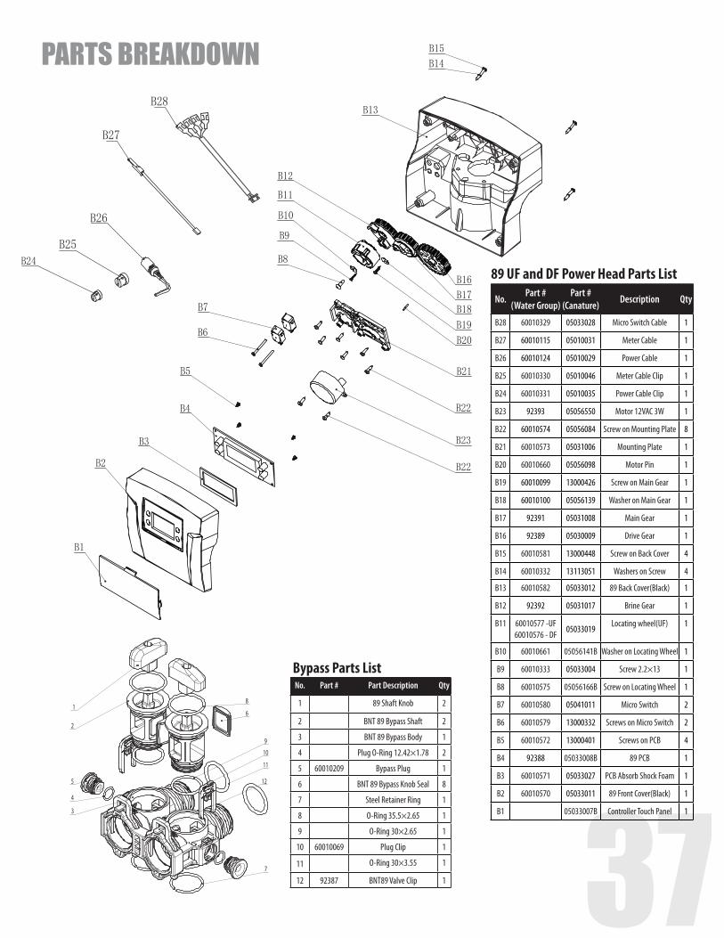
Bypass Parts ListNo. Part # Part Description Qty
1 89 Shaft Knob 2
2 BNT 89 Bypass Shaft 2
3 BNT 89 Bypass Body 1
4 Plug O-Ring 12.42×1.78 2
5 60010209 Bypass Plug 1
6 BNT 89 Bypass Knob Seal 8
7 Steel Retainer Ring 1
8 O-Ring 35.5×2.65 1
9 O-Ring 30×2.65 1
10 60010069 Plug Clip 1
11 O-Ring 30×3.55 1
12 92387 BNT89 Valve Clip 1
89 UF and DF Power Head Parts List
No.Part #
(Water Group)Part #
(Canature)Description Qty
B28 60010329 05033028 Micro Switch Cable 1
B27 60010115 05010031 Meter Cable 1
B26 60010124 05010029 Power Cable 1
B25 60010330 05010046 Meter Cable Clip 1
B24 60010331 05010035 Power Cable Clip 1
B23 92393 05056550 Motor 12VAC 3W 1
B22 60010574 05056084 Screw on Mounting Plate 8
B21 60010573 05031006 Mounting Plate 1
B20 60010660 05056098 Motor Pin 1
B19 60010099 13000426 Screw on Main Gear 1
B18 60010100 05056139 Washer on Main Gear 1
B17 92391 05031008 Main Gear 1
B16 92389 05030009 Drive Gear 1
B15 60010581 13000448 Screw on Back Cover 4
B14 60010332 13113051 Washers on Screw 4
B13 60010582 05033012 89 Back Cover(Black) 1
B12 92392 05031017 Brine Gear 1
B11 60010577 -UF 60010576 - DF
05033019Locating wheel(UF) 1
B10 60010661 05056141B Washer on Locating Wheel 1
B9 60010333 05033004 Screw 2.2×13 1
B8 60010575 05056166B Screw on Locating Wheel 1
B7 60010580 05041011 Micro Switch 2
B6 60010579 13000332 Screws on Micro Switch 2
B5 60010572 13000401 Screws on PCB 4
B4 92388 05033008B 89 PCB 1
B3 60010571 05033027 PCB Absorb Shock Foam 1
B2 60010570 05033011 89 Front Cover(Black) 1
B1 05033007B Controller Touch Panel 1
PARTS BREAKDOWN
38
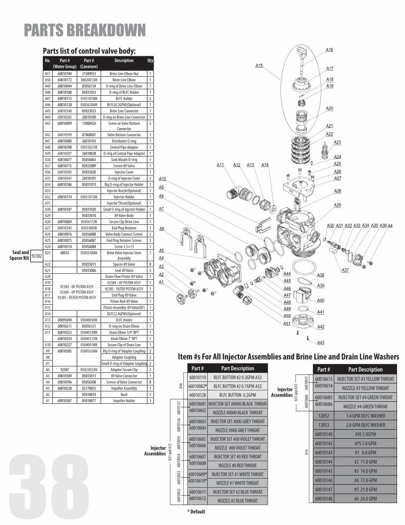
Item #s For All Injector Assemblies and Brine Line and Drain Line WashersPart # Part Description
60010110 BLFC BUTTON #2 0.3GPM A32
60010082* BLFC BUTTON #2 0.7GPM A32
60010128 BLFC BUTTON 0.2GPM
60010601 60010602
INJECTOR SET #0000 BLACK THROAT
NOZZLE #0000 BLACK THROAT
6001060360010604
INJECTOR SET #000 GREY THROAT
NOZZLE #000 GREY THROAT
60010605 60010606
INJECTOR SET #00 VIOLET THROAT
NOZZLE #00 VIOLET THROAT
60010607 60010608
INJECTOR SET #0 RED THROAT
NOZZLE #0 RED THROAT
60010609* 60010610*
INJECTOR SET #1 WHITE THROAT
NOZZLE #1 WHITE THROAT
60010611 60010612
INJECTOR SET #2 BLUE THROAT
NOZZLE #2 BLUE THROAT
A46
A31 a
nd A3
3
* Default
Injector Assemblies
6001
0127
6001
0126
6001
0032
6001
0033
6001
0034
6001
0035
Part # Part Description60010613 60010614
INJECTOR SET #3 YELLOW THROAT
NOZZLE #3 YELLOW THROAT
6001068560010686
INJECTOR SET #4 GREEN THROAT
NOZZLE #4 GREEN THROAT
12052 1.4 GPM DLFC WASHER
12053 2.0 GPM DLFC WASHER
60010140 #4S 5.0GPM
60010142 #7S 7.0 GPM
60010143 #1 8.0 GPM
60010144 #2 11.0 GPM
60010145 #3 14.0 GPM
60010146 #4 17.0 GPM
60010147 #5 21.0 GPM
60010148 #6 24.0 GPM
A31 a
nd A3
3
A14
Injector Assemblies
6001
0031
6001
0686
Parts list of control valve body:No. Part #
(Water Group)Part #
(Canature)Description Qty
A51 60010184 21389033 Brine Line Elbow Nut 1A50 60010172 30020013M Brine Line Elbow 1A49 60010044 05056134 O-ring of Brine Line Elbow 1A48 60010188 05031033 O-ring of BLFC Holder 1A47 60010173 05031010M BLFC Holder 2A46 60010128 05056206M BLFC(0.2GPM)(Optional) 1A45 60010340 05033033 Brine Line Connector 1A44 60010265 26010189 O-ring on Brine Line Connector 1A43 60010099 13000426 Screw on Valve Bottom
Connector2
A42 60010599 07060007 Valve Bottom Connector 1A41 60010080 26010103 Distributor O-ring 1A40 60010598 05033021M Central Pipe Adaptor 1A39 60010597 26010038 O-ring of Central Pipe Adaptor 1A38 60010077 05056063 Tank Mouth O-ring 1A37 60010715 05033009 Screen 89 Valve 1A36 60010595 05033020 Injector Cover 1A35 60010341 26010101 O-ring of Injector Cover 1A34 60010186 05031019 Big O-ring of Injector Holder 1A33 Injector Nozzle(Optional) 1A32 60010174 05031012M Injector Holder 1A31 Injector Throat(Optional) 1A30 60010187 05031020 Small O-ring of Injector Holder 1A29 05033010 89 Valve Body 1A28 60010069 05056172N Secure Clip Brine Line 1A27 60010343 05033005B End Plug Retainer 1A26 60010076 05056088 Valve Body Connect Screws 2A25 60010075 05056087 End Plug Retainer Screws 3A24 60010574 05056084 Screw 3.5×13 1A23 60032 05056180M Brine Valve Injector Stem
Assembly1
A22 05033015 Spacer-89 Valve 8A21 05033006 Seal-89 Valve 5A20
92383 - DF PISTON ASSY 92384 - UP PISTON ASSY
92385 - FILTER PISTON ASSY
Down Flow Piston-89 Valve 1A19 92384 - UP PISTON ASSY 1A18 92385 - FILTER PISTON ASSY 1A17 End Plug-89 Valve 1A16 Piston Rod-89 Valve 1A15 Piston Assembly-89 Valve(DF) 1A14 DLFC(2.4GPM)(Optional) 1A13 60095694 05040030M DLFC Holder 1A12 60010211 05056121 O-ring on Drain Elbow 1A11 60010253 05040130M Drain Elbow 3/4” NPT 1
60010254 05040131M Drain Elbow 1” NPT 1A10 60010227 05040018M Secure Clip of Drain Line 1A9 60010585 05005636M Big O-ring of Adaptor Coupling 2A8 Adaptor Coupling 2A7 Small O-ring of Adaptor Coupling 2A6 92387 05033022M Adaptor Secure Clip 2A5 60010589 05033013 89 Valve Connector 1A4 60010596 05056508 Screws of Valve Connector 8A3 60010238 02170055 Impeller Assembly 1A2 05010019 Bush 2A1 60010587 05010077 Impeller Holder 1
Seal and Spacer Kit 92382
PARTS BREAKDOWN
38 39
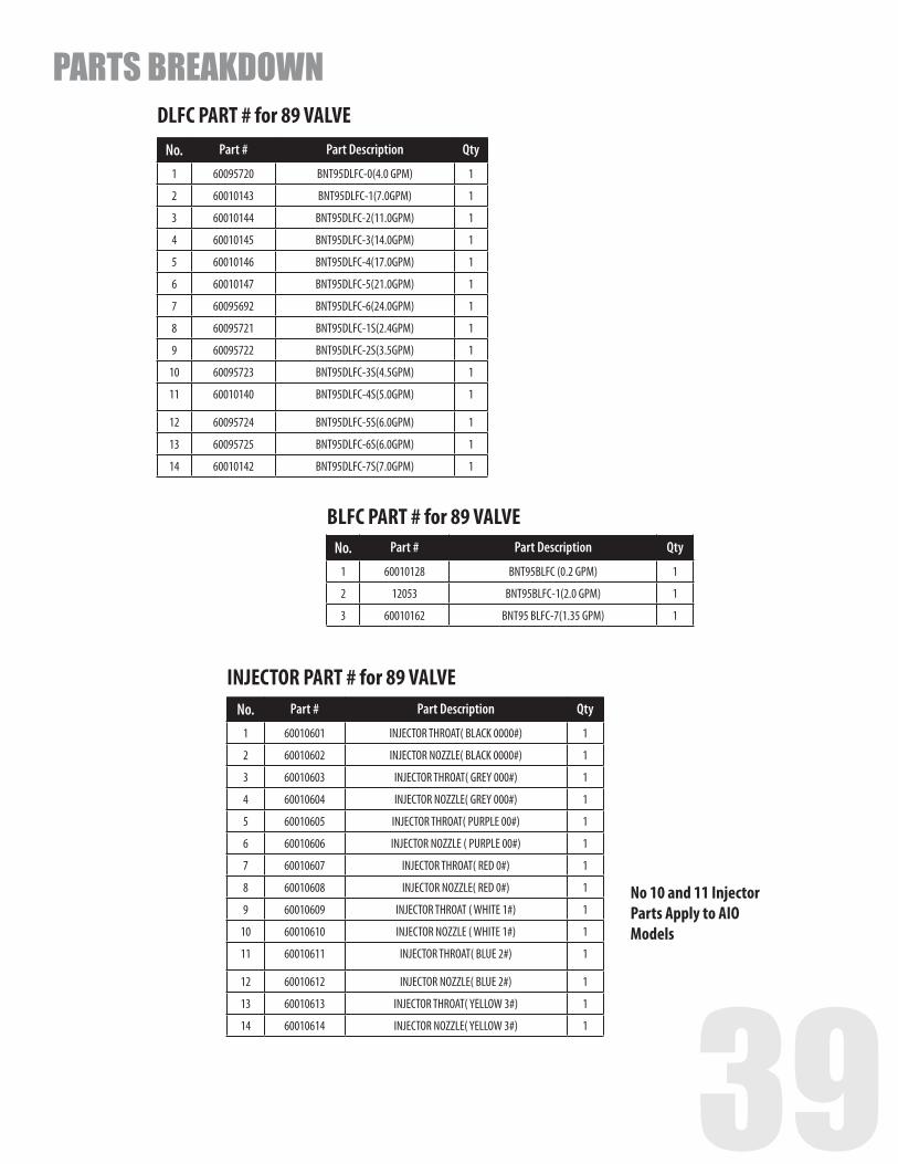
DLFC PART # for 89 VALVENo. Part # Part Description Qty
1 60095720 BNT95DLFC-0(4.0 GPM) 1
2 60010143 BNT95DLFC-1(7.0GPM) 1
3 60010144 BNT95DLFC-2(11.0GPM) 1
4 60010145 BNT95DLFC-3(14.0GPM) 1
5 60010146 BNT95DLFC-4(17.0GPM) 1
6 60010147 BNT95DLFC-5(21.0GPM) 1
7 60095692 BNT95DLFC-6(24.0GPM) 1
8 60095721 BNT95DLFC-1S(2.4GPM) 1
9 60095722 BNT95DLFC-2S(3.5GPM) 1
10 60095723 BNT95DLFC-3S(4.5GPM) 1
11 60010140 BNT95DLFC-4S(5.0GPM) 1
12 60095724 BNT95DLFC-5S(6.0GPM) 1
13 60095725 BNT95DLFC-6S(6.0GPM) 1
14 60010142 BNT95DLFC-7S(7.0GPM) 1
BLFC PART # for 89 VALVENo. Part # Part Description Qty
1 60010128 BNT95BLFC (0.2 GPM) 1
2 12053 BNT95BLFC-1(2.0 GPM) 1
3 60010162 BNT95 BLFC-7(1.35 GPM) 1
INJECTOR PART # for 89 VALVENo. Part # Part Description Qty
1 60010601 INJECTOR THROAT( BLACK 0000#) 1
2 60010602 INJECTOR NOZZLE( BLACK 0000#) 1
3 60010603 INJECTOR THROAT( GREY 000#) 1
4 60010604 INJECTOR NOZZLE( GREY 000#) 1
5 60010605 INJECTOR THROAT( PURPLE 00#) 1
6 60010606 INJECTOR NOZZLE ( PURPLE 00#) 1
7 60010607 INJECTOR THROAT( RED 0#) 1
8 60010608 INJECTOR NOZZLE( RED 0#) 1
9 60010609 INJECTOR THROAT ( WHITE 1#) 1
10 60010610 INJECTOR NOZZLE ( WHITE 1#) 1
11 60010611 INJECTOR THROAT( BLUE 2#) 1
12 60010612 INJECTOR NOZZLE( BLUE 2#) 1
13 60010613 INJECTOR THROAT( YELLOW 3#) 1
14 60010614 INJECTOR NOZZLE( YELLOW 3#) 1
PARTS BREAKDOWN
No 10 and 11 Injector Parts Apply to AIO Models
40
PARTS BREAKDOWN
1
2
3
4
5
6
10
11
12
13
14
15
7
8
9
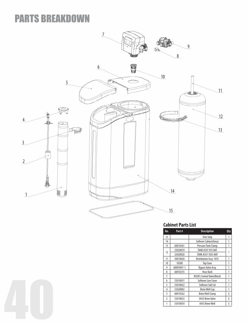
Cabinet Parts ListNo. Part # Description Qty
15 Trim Strip 114 Softener Cabinet(Grey) 113 60010361 Pressure Tank Clamp 1
1225020019 TANK ASSY 935 NAT
125020020 TANK ASSY 1035 NAT
11 50010020 Distribution Assy-1035 110 18280 Top Cone 19 60095097-1 Bypass Valve Assy 18 60010255 Hose Barb 17 89(UF) Control Valve(Black) 16 55010031 Softener Low Cover 15 55010032 Softener Salt Lid 14 55020002 Brine Well Cap 13 60010362 Brine Well Clamp 12 55010023 0435 Brine Valve 11 55010010 0435 Brine Well 1
40 41
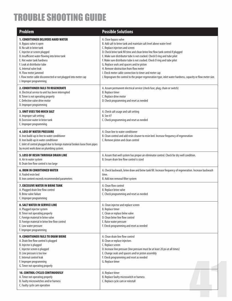
Problem Possible Solutions1. CONDITIONER DELIVERS HARD WATER A. Bypass valve is open B. No salt in brine tank C. Injector or screen plugged D. Insufficient water flowing into brine tank E. Hot water tank hardness F. Leak at distributor tube G. Internal valve leak H. Flow meter jammed I. Flow meter cable disconnected or not plugged into meter cap J. Improper programming
A. Close bypass valve B. Add salt to brine tank and maintain salt level above water level C. Replace injectors and screen D. Check brine tank fill time and clean brine line flow tank control if plugged E. Make sure distributor tube is not cracked. Check O ring and tube pilot F. Make sure distributor tube is not cracked. Check O ring and tube pilot G. Replace seals and spacers and/or piston H. Remove obstruction from flow meter I. Check meter cable connection to timer and meter cap J. Reprogram the control to the proper regeneration type, inlet water hardness, capacity or flow meter size.
2. CONDITIONER FAILS TO REGENERATE A. Electrical service to unit has been interrupted B. Timer is not operating properly C. Defective valve drive motor D. Improper programming
A. Assure permanent electrical service (check fuse, plug, chain or switch) B. Replace timer C. Replace drive motor D. Check programming and reset as needed
3. UNIT USES TOO MUCH SALT A. Improper salt setting B. Excessive water in brine tank C. Improper programming
A. Check salt usage and salt setting B. See #7 C. Check programming and reset as needed
4. LOSS OF WATER PRESSURE A. Iron build-up in line to water conditioner B. Iron build-up in water conditioner C. Inlet of control plugged due to foreign material broken loose from pipes by recent work done on plumbing system.
A. Clean line to water conditioner B. Clean control and add resin cleaner to resin bed. Increase frequency of regeneration C. Remove piston and clean control
5. LOSS OF RESIN THROUGH DRAIN LINE A. Air in water system B. Drain line flow control is too large
A. Assure that well system has proper air eliminator control. Check for dry well condition. B. Ensure drain line flow control is sized
6. IRON IN CONDITIONED WATER A. Fouled resin bed B. Iron content exceeds recommended parameters
A. Check backwash, brine draw and brine tank fill. Increase frequency of regeneration. Increase backwash time. B. Add iron removal filter system
7. EXCESSIVE WATER IN BRINE TANK A. Plugged drain line flow control B. Brine valve failure C. Improper programming
A. Clean flow control B. Replace brine valve C. Check programming and reset as needed
8. SALT WATER IN SERVICE LINE A. Plugged injector system B. Timer not operating properly C. Foreign material in brine valve D. Foreign material in brine line flow control E. Low water pressure F. Improper programming
A. Clean injector and replace screen B. Replace timer C. Clean or replace brine valve D. Clean brine line flow control E. Raise water pressure F. Check programming and reset as needed
9. CONDITIONER FAILS TO DRAW BRINE A. Drain line flow control is plugged B. Injector is plugged C. Injector screen is plugged D. Line pressure is too low E. Internal control leak F. Improper programming G. Timer not operating properly
A. Clean drain line flow control B. Clean or replace injectors C. Replace screen D. Increase line pressure (line pressure must be at least 20 psi at all times) E. Change seals and spacers and/or piston assembly F. Check programming and reset as needed G. Replace timer
10. CONTROL CYCLES CONTINUOUSLY A. Timer not operating properly B. Faulty microswitches and/or harness C. Faulty cycle cam operation
A. Replace timer B. Replace faulty microswitch or harness C. Replace cycle cam or reinstall
TROUBLE SHOOTING GUIDE

42
Problem Possible Solutions11. DRAIN FLOWS CONTINUOUSLY A. Foreign material in control B. Internal control leak C. Control valve jammed in brine or backwash position D. Timer motor stopped or jammed teeth E. Timer not operating properly
A. Remove piston assembly and inspect bore. Remove foreign material and check control in various regener-ation positions B. Replace seals and/or piston assembly C. Replace piston and seals and spacers D. Replace timer motor and check all gears for missing teeth E. Replace timer
12. (Error Code) (Error E1) - Electrical Trouble Shooting: Issue1: When the controller is plugged, the buzzer beeps and the screen displays ” System Error E1”Cause: The wire of micro switch is not plugged or loose.
Check the micro switch and connect the wire well.
13. (Error Code) (Error E1) - Electrical Trouble Shooting: Issue 2: The buzzer beeps and the screen displays “System Maintaining E1”Cause: The wire of micro switch is not plugged or loose..
Check the micro switch and connect the wire.
14. (Error Code) (Error E2) - Electrical Trouble Shooting: Issue: The buzzer beeps and the screen displays “System Error E2”Cause: The motor can not find its right position, micro switch or motor mal-function, automatic circuit protection action.
Check the current of micro switch and motor.
15. (Error Code) (Error E2) - Electrical Trouble Shooting: Issue 2: The buzzer beeps and the screen displayed “ System Maintaining E2” Cause: The motor can not find its right position.
Replace Motor or PCB.
TROUBLE SHOOTING GUIDE
PRESS ‘+’ AND ‘-’ FOR 8 SECONDS PRESS MENU KEY AND SCROLL TO ‘MAIN MENU’. THEN PRESS ‘SET’ TILL IT BEEPS. SCROLL TO ADVANCED MENU
PRESS MENU KEY AND SCROLL TO ‘MAIN MENU’. THEN PRESS ‘SET’ TILL IT BEEPS
VALVE SETTINGS
MODELS LANGUAGE REGION VALVEMETER RATIO
SALT VS EFFICIENCY
AUTO CALCULATION
RESIN VOLUME
REFILL RATE
REGEN. MODEBACKWASH OVERRIDE
EMERGENCY REGEN.
REGEN CYCLES
BRINE / RINSE
BACK WASH
RINSEREGEN TIME
SETTINGSALT MODE
SETTING
BRINE PREFILL
SETPREFILL Injector
Injector Color
BLFC Washer
DLFC Washer
DLFC Washer
Code
75 ENGLISH US GALLONS UPFLOW 1.234 DONT TOUCH ON 0.75CF 0.2 GPM METER DELAY OFF ON 90 15 15 2:00AM STANDARD ON 70% #0000 Black 0.2 GPM 1.35 #7
100 ENGLISH US GALLONS UPFLOW 1.234 DONT TOUCH ON 1.0CF 0.2 GPM METER DELAY OFF ON 90 15 15 2:00AM STANDARD ON 70% #0000 Black 0.2 GPM 2.0 #2
150 ENGLISH US GALLONS UPFLOW 1.234 DONT TOUCH ON 1.5CF 0.2 GPM METER DELAY OFF ON 90 15 15 2:00AM STANDARD ON 70% #0000 Black 0.2 GPM 2.4 1S
200 ENGLISH US GALLONS UPFLOW 1.234 DONT TOUCH ON 2.0CF 0.2 GPM METER DELAY OFF ON 90 15 15 2:00AM STANDARD ON 70% #00 Purple 0.2 GPM 3.5 2S
250 ENGLISH US GALLONS UPFLOW 1.234 DONT TOUCH ON 2.5CF 0.2 GPM METER DELAY OFF ON 90 15 15 2:00AM STANDARD ON 70% #00 Purple 0.2 GPM 4.0 3S
300 ENGLISH US GALLONS UPFLOW 1.234 DONT TOUCH ON 3CF 0.2 GPM METER DELAY OFF ON 90 15 15 2:00AM STANDARD ON 70% #1 White 0.2 GPM 5.0 4S
Upflow Valve Programming (Models 89UF)
Below is how the settings are set at factory:
PRESS ‘+’ AND ‘-’ FOR 8 SECONDS PRESS MENU KEY AND SCROLL TO ‘MAIN MENU’. THEN PRESS ‘SET’ TILL IT BEEPS. SCROLL TO ADVANCED MENU
PRESS MENU KEY AND SCROLL TO ‘MAIN MENU’. THEN PRESS ‘SET’ TILL
IT BEEPS
VALVE SETTINGS
MODELS LANGUAGE REGION VALVE METER RATIO
SALT VS EFFICIENCY
AUTO CALCULATION
RESIN VOLUME
REFILL RATE
REGEN. MODE BACKWASH OVERRIDE
EMERGENCY REGEN.
REGEN CYCLES
BACK WASH DURATION
BRINE DRAW
DURATION
RINSE DURATION
REFILL DURATION
REGEN TIME
SETTING
REGEN DAY
SETTING
SYSTEM CAPACITY
SALT MODE
SETTING
Injector Injector Color
BLFC Washer
DLFC Washer
DLFC Washer
Code
75 ENGLISH US GALLONS DOWNFLOW 1.393 DONT TOUCH ON 0.75CF 0.7 GPM METER DELAY OFF OFF 10 60 10 N/A 2:00AM N/A N/A STAN-DARD
#1 White 0.7 GPM 1.4 #7
100 ENGLISH US GALLONS DOWNFLOW 1.393 DONT TOUCH ON 1.0CF 0.7 GPM METER DELAY OFF OFF 10 60 10 N/A 2:00AM N/A N/A STAN-DARD
#1 White 0.7 GPM 2.0 #2
150 ENGLISH US GALLONS DOWNFLOW 1.393 DONT TOUCH ON 1.5CF 0.7 GPM METER DELAY OFF OFF 10 60 10 N/A 2:00AM N/A N/A STAN-DARD
#1 White 0.7 GPM 2.4 1S
200 ENGLISH US GALLONS DOWNFLOW 1.393 DONT TOUCH ON 2.0CF 0.7 GPM METER DELAY OFF OFF 10 60 10 N/A 2:00AM N/A N/A STAN-DARD
#2 Blue 0.7 GPM 3.5 2S
250 ENGLISH US GALLONS DOWNFLOW 1.393 DONT TOUCH ON 2.5CF 0.7 GPM METER DELAY OFF OFF 10 60 10 N/A 2:00AM N/A N/A STAN-DARD
#2 Blue 0.7 GPM 4.0 3S
300 ENGLISH US GALLONS DOWNFLOW 1.393 DONT TOUCH ON 3CF 0.7 GPM METER DELAY OFF OFF 10 60 10 N/A 2:00AM N/A N/A STAN-DARD
#3 Yellow 0.7 GPM 5.0 4S
Downflow Valve Programming (Models 89DF)
MASTER PROGRAMMING GUIDE
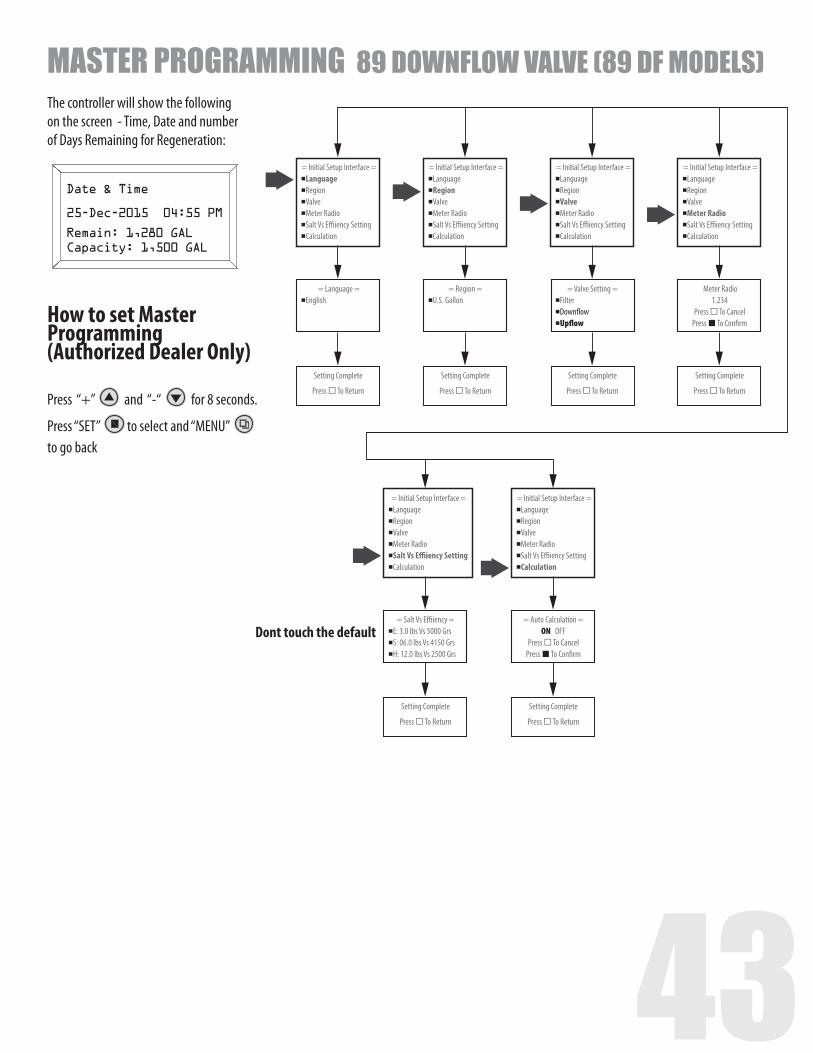
42 43
MENU
SET
Date & Time
25-Dec-2015 04:55 PM
Remain: 1,280 GALCapacity: 1,500 GAL
= Initial Setup Interface =LanguageRegionValveMeter RadioSalt Vs E�iency SettingCalculation
= Initial Setup Interface =LanguageRegionValveMeter RadioSalt Vs E�iency SettingCalculation
= Initial Setup Interface =LanguageRegionValveMeter RadioSalt Vs E�iency SettingCalculation
= Initial Setup Interface =LanguageRegionValveMeter RadioSalt Vs E�iency SettingCalculation
= Language =English
= Region =U.S. Gallon
= Valve Setting =FilterDown�owUp�ow
Meter Radio1.234
Press To CancelPress To Con�rm
Setting Complete
Press To Return
Setting Complete
Press To Return
= Initial Setup Interface =LanguageRegionValveMeter RadioSalt Vs E�iency SettingCalculation
= Salt Vs E�iency =E: 3.0 lbs Vs 5000 Grs
S: 06.0 lbs Vs 4150 Grs H: 12.0 lbs Vs 2500 Grs
Setting Complete
Press To Return
= Initial Setup Interface =LanguageRegionValveMeter RadioSalt Vs E�iency SettingCalculation
= Auto Calculation =ON OFF
Press To CancelPress To Con�rm
Setting Complete
Press To Return
Setting Complete
Press To Return
Setting Complete
Press To Return
Dont touch the default
PRESS ‘+’ AND ‘-’ FOR 8 SECONDS PRESS MENU KEY AND SCROLL TO ‘MAIN MENU’. THEN PRESS ‘SET’ TILL IT BEEPS. SCROLL TO ADVANCED MENU
PRESS MENU KEY AND SCROLL TO ‘MAIN MENU’. THEN PRESS ‘SET’ TILL
IT BEEPS
VALVE SETTINGS
MODELS LANGUAGE REGION VALVE METER RATIO
SALT VS EFFICIENCY
AUTO CALCULATION
RESIN VOLUME
REFILL RATE
REGEN. MODE BACKWASH OVERRIDE
EMERGENCY REGEN.
REGEN CYCLES
BACK WASH DURATION
BRINE DRAW
DURATION
RINSE DURATION
REFILL DURATION
REGEN TIME
SETTING
REGEN DAY
SETTING
SYSTEM CAPACITY
SALT MODE
SETTING
Injector Injector Color
BLFC Washer
DLFC Washer
DLFC Washer
Code
75 ENGLISH US GALLONS DOWNFLOW 1.393 DONT TOUCH ON 0.75CF 0.7 GPM METER DELAY OFF OFF 10 60 10 N/A 2:00AM N/A N/A STAN-DARD
#1 White 0.7 GPM 1.4 #7
100 ENGLISH US GALLONS DOWNFLOW 1.393 DONT TOUCH ON 1.0CF 0.7 GPM METER DELAY OFF OFF 10 60 10 N/A 2:00AM N/A N/A STAN-DARD
#1 White 0.7 GPM 2.0 #2
150 ENGLISH US GALLONS DOWNFLOW 1.393 DONT TOUCH ON 1.5CF 0.7 GPM METER DELAY OFF OFF 10 60 10 N/A 2:00AM N/A N/A STAN-DARD
#1 White 0.7 GPM 2.4 1S
200 ENGLISH US GALLONS DOWNFLOW 1.393 DONT TOUCH ON 2.0CF 0.7 GPM METER DELAY OFF OFF 10 60 10 N/A 2:00AM N/A N/A STAN-DARD
#2 Blue 0.7 GPM 3.5 2S
250 ENGLISH US GALLONS DOWNFLOW 1.393 DONT TOUCH ON 2.5CF 0.7 GPM METER DELAY OFF OFF 10 60 10 N/A 2:00AM N/A N/A STAN-DARD
#2 Blue 0.7 GPM 4.0 3S
300 ENGLISH US GALLONS DOWNFLOW 1.393 DONT TOUCH ON 3CF 0.7 GPM METER DELAY OFF OFF 10 60 10 N/A 2:00AM N/A N/A STAN-DARD
#3 Yellow 0.7 GPM 5.0 4S
MASTER PROGRAMMING 89 DOWNFLOW VALVE (89 DF MODELS)The controller will show the following on the screen - Time, Date and number of Days Remaining for Regeneration:
How to set Master Programming (Authorized Dealer Only)
Press “+” and “-“ for 8 seconds.
Press “SET” to select and “MENU” to go back
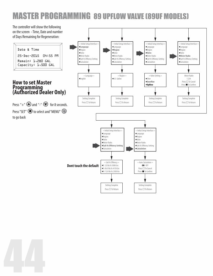
44
MENU
SET
Date & Time
25-Dec-2015 04:55 PM
Remain: 1,280 GALCapacity: 1,500 GAL
= Initial Setup Interface =LanguageRegionValveMeter RadioSalt Vs E�iency SettingCalculation
= Initial Setup Interface =LanguageRegionValveMeter RadioSalt Vs E�iency SettingCalculation
= Initial Setup Interface =LanguageRegionValveMeter RadioSalt Vs E�iency SettingCalculation
= Initial Setup Interface =LanguageRegionValveMeter RadioSalt Vs E�iency SettingCalculation
= Language =English
= Region =U.S. Gallon
= Valve Setting =FilterDown�owUp�ow
Meter Radio1.234
Press To CancelPress To Con�rm
Setting Complete
Press To Return
Setting Complete
Press To Return
= Initial Setup Interface =LanguageRegionValveMeter RadioSalt Vs E�iency SettingCalculation
= Salt Vs E�iency =E: 3.0 lbs Vs 5000 Grs
S: 06.0 lbs Vs 4150 Grs H: 12.0 lbs Vs 2500 Grs
Setting Complete
Press To Return
= Initial Setup Interface =LanguageRegionValveMeter RadioSalt Vs E�iency SettingCalculation
= Auto Calculation =ON OFF
Press To CancelPress To Con�rm
Setting Complete
Press To Return
Setting Complete
Press To Return
Setting Complete
Press To Return
Dont touch the default
MASTER PROGRAMMING 89 UPFLOW VALVE (89UF MODELS)The controller will show the following on the screen - Time, Date and number of Days Remaining for Regeneration:
How to set Master Programming (Authorized Dealer Only)
Press “+” and “-“ for 8 seconds.
Press “SET” to select and “MENU” to go back
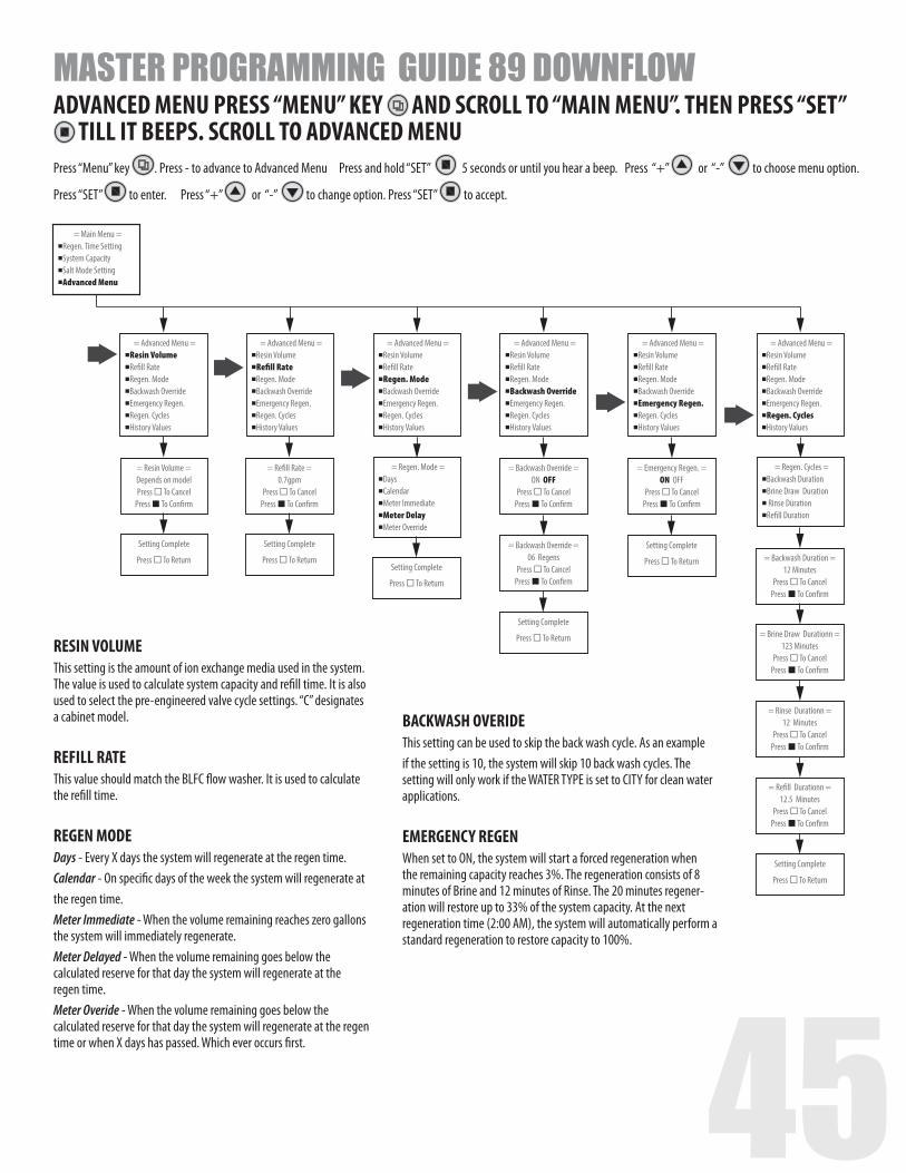
44 45
= Advanced Menu =Resin VolumeRe�ll RateRegen. ModeBackwash OverrideEmergency Regen.Regen. CyclesHistory Values
= Main Menu =Regen. Time SettingSystem CapacitySalt Mode SettingAdvanced Menu
= Resin Volume =Depends on modelPress To Cancel
Press To Con�rm
= Backwash Override =ON OFF
Press To CancelPress To Con�rm
= Advanced Menu =Resin VolumeRe�ll RateRegen. ModeBackwash OverrideEmergency Regen.Regen. CyclesHistory Values
= Regen. Mode =DaysCalendarMeter ImmediateMeter DelayMeter Override
= Advanced Menu =Resin VolumeRe�ll RateRegen. ModeBackwash OverrideEmergency Regen.Regen. CyclesHistory Values
Setting Complete
Press To Return
= Re�ll Rate =0.7gpm
Press To CancelPress To Con�rm
Setting Complete
Press To ReturnSetting Complete
Press To Return
= Advanced Menu =Resin VolumeRe�ll RateRegen. ModeBackwash OverrideEmergency Regen.Regen. CyclesHistory Values
= Backwash Duration =12 Minutes
Press To CancelPress To Con�rm
= Brine Draw Durationn =123 Minutes
Press To CancelPress To Con�rm
= Rinse Durationn =12 Minutes
Press To CancelPress To Con�rm
= Re�ll Durationn =12.5 Minutes
Press To CancelPress To Con�rm
= Backwash Override =06 Regens
Press To CancelPress To Con�rm
Setting Complete
Press To Return
= Emergency Regen. =ON OFF
Press To CancelPress To Con�rm
= Advanced Menu =Resin VolumeRe�ll RateRegen. ModeBackwash OverrideEmergency Regen.Regen. CyclesHistory Values
Setting Complete
Press To Return
= Advanced Menu =Resin VolumeRe�ll RateRegen. ModeBackwash OverrideEmergency Regen.Regen. CyclesHistory Values
Setting Complete
Press To Return
= Regen. Cycles =Backwash DurationBrine Draw Duration Rinse DurationRe�ll Duration
ADVANCED MENU PRESS “MENU” KEY AND SCROLL TO “MAIN MENU”. THEN PRESS “SET” TILL IT BEEPS. SCROLL TO ADVANCED MENU
Press “Menu” key . Press - to advance to Advanced Menu Press and hold “SET” 5 seconds or until you hear a beep. Press “+” or “-” to choose menu option.
Press “SET” to enter. Press “+” or “-” to change option. Press “SET” to accept.
MASTER PROGRAMMING GUIDE 89 DOWNFLOW
RESIN VOLUME This setting is the amount of ion exchange media used in the system. The value is used to calculate system capacity and refill time. It is also used to select the pre-engineered valve cycle settings. “C” designates a cabinet model. REFILL RATEThis value should match the BLFC flow washer. It is used to calculate the refill time. REGEN MODEDays - Every X days the system will regenerate at the regen time.Calendar - On specific days of the week the system will regenerate at the regen time.Meter Immediate - When the volume remaining reaches zero gallons the system will immediately regenerate.Meter Delayed - When the volume remaining goes below the calculated reserve for that day the system will regenerate at the regen time.Meter Overide - When the volume remaining goes below the calculated reserve for that day the system will regenerate at the regen time or when X days has passed. Which ever occurs first.
BACKWASH OVERIDEThis setting can be used to skip the back wash cycle. As an example if the setting is 10, the system will skip 10 back wash cycles. The setting will only work if the WATER TYPE is set to CITY for clean water applications. EMERGENCY REGENWhen set to ON, the system will start a forced regeneration when the remaining capacity reaches 3%. The regeneration consists of 8 minutes of Brine and 12 minutes of Rinse. The 20 minutes regener-ation will restore up to 33% of the system capacity. At the next regeneration time (2:00 AM), the system will automatically perform a standard regeneration to restore capacity to 100%.
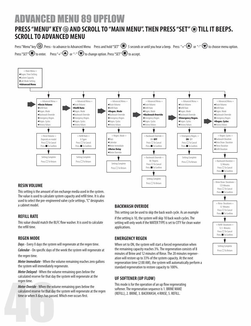
46
= Advanced Menu =Resin VolumeRe�ll RateRegen. ModeBackwash OverrideEmergency Regen.Regen. CyclesHistory Values
= Main Menu =Regen. Time SettingSystem CapacitySalt Mode SettingAdvanced Menu
= Resin Volume =Depends on modelPress To Cancel
Press To Con�rm
= Backwash Override =ON OFF
Press To CancelPress To Con�rm
= Advanced Menu =Resin VolumeRe�ll RateRegen. ModeBackwash OverrideEmergency Regen.Regen. CyclesHistory Values
= Regen. Mode =DaysCalendarMeter ImmediateMeter DelayMeter Override
= Advanced Menu =Resin VolumeRe�ll RateRegen. ModeBackwash OverrideEmergency Regen.Regen. CyclesHistory Values
Setting Complete
Press To Return
= Re�ll Rate =0.7gpm
Press To CancelPress To Con�rm
Setting Complete
Press To ReturnSetting Complete
Press To Return
= Advanced Menu =Resin VolumeRe�ll RateRegen. ModeBackwash OverrideEmergency Regen.Regen. CyclesHistory Values
= Backwash Duration =12 Minutes
Press To CancelPress To Con�rm
= Brine Draw Durationn =123 Minutes
Press To CancelPress To Con�rm
= Rinse Durationn =12 Minutes
Press To CancelPress To Con�rm
= Re�ll Durationn =12.5 Minutes
Press To CancelPress To Con�rm
= Backwash Override =06 Regens
Press To CancelPress To Con�rm
Setting Complete
Press To Return
= Emergency Regen. =ON OFF
Press To CancelPress To Con�rm
= Advanced Menu =Resin VolumeRe�ll RateRegen. ModeBackwash OverrideEmergency Regen.Regen. CyclesHistory Values
Setting Complete
Press To Return
= Advanced Menu =Resin VolumeRe�ll RateRegen. ModeBackwash OverrideEmergency Regen.Regen. CyclesHistory Values
Setting Complete
Press To Return
= Regen. Cycles =Backwash DurationBrine Draw Duration Rinse DurationRe�ll Duration
PRESS “MENU” KEY AND SCROLL TO “MAIN MENU”. THEN PRESS “SET” TILL IT BEEPS. SCROLL TO ADVANCED MENU Press “Menu” key . Press - to advance to Advanced Menu Press and hold “SET” 5 seconds or until you hear a beep. Press “+” or “-” to choose menu option.
Press “SET” to enter. Press “+” or “-” to change option. Press “SET” to accept.
ADVANCED MENU 89 UPFLOW
RESIN VOLUME This setting is the amount of ion exchange media used in the system. The value is used to calculate system capacity and refill time. It is also used to select the pre-engineered valve cycle settings. “C” designates a cabinet model. REFILL RATEThis value should match the BLFC flow washer. It is used to calculate the refill time. REGEN MODEDays - Every X days the system will regenerate at the regen time.Calendar - On specific days of the week the system will regenerate at the regen time.Meter Immediate - When the volume remaining reaches zero gallons the system will immediately regenerate.Meter Delayed - When the volume remaining goes below the calculated reserve for that day the system will regenerate at the regen time.Meter Overide - When the volume remaining goes below the calculated reserve for that day the system will regenerate at the regen time or when X days has passed. Which ever occurs first.
BACKWASH OVERIDEThis setting can be used to skip the back wash cycle. As an example if the setting is 10, the system will skip 10 back wash cycles. The setting will only work if the WATER TYPE is set to CITY for clean water applications. EMERGENCY REGENWhen set to ON, the system will start a forced regeneration when the remaining capacity reaches 3%. The regeneration consists of 8 minutes of Brine and 12 minutes of Rinse. The 20 minutes regener-ation will restore up to 33% of the system capacity. At the next regeneration time (2:00 AM), the system will automatically perform a standard regeneration to restore capacity to 100%. UF SOFTENER (UP FLOW)This mode is for the operation of an up flow regeneratingsoftener. The regeneration sequence is 1. BRINE MAKE(REFILL), 2. BRINE, 3. BACKWASH, 4 RINSE, 5. REFILL.
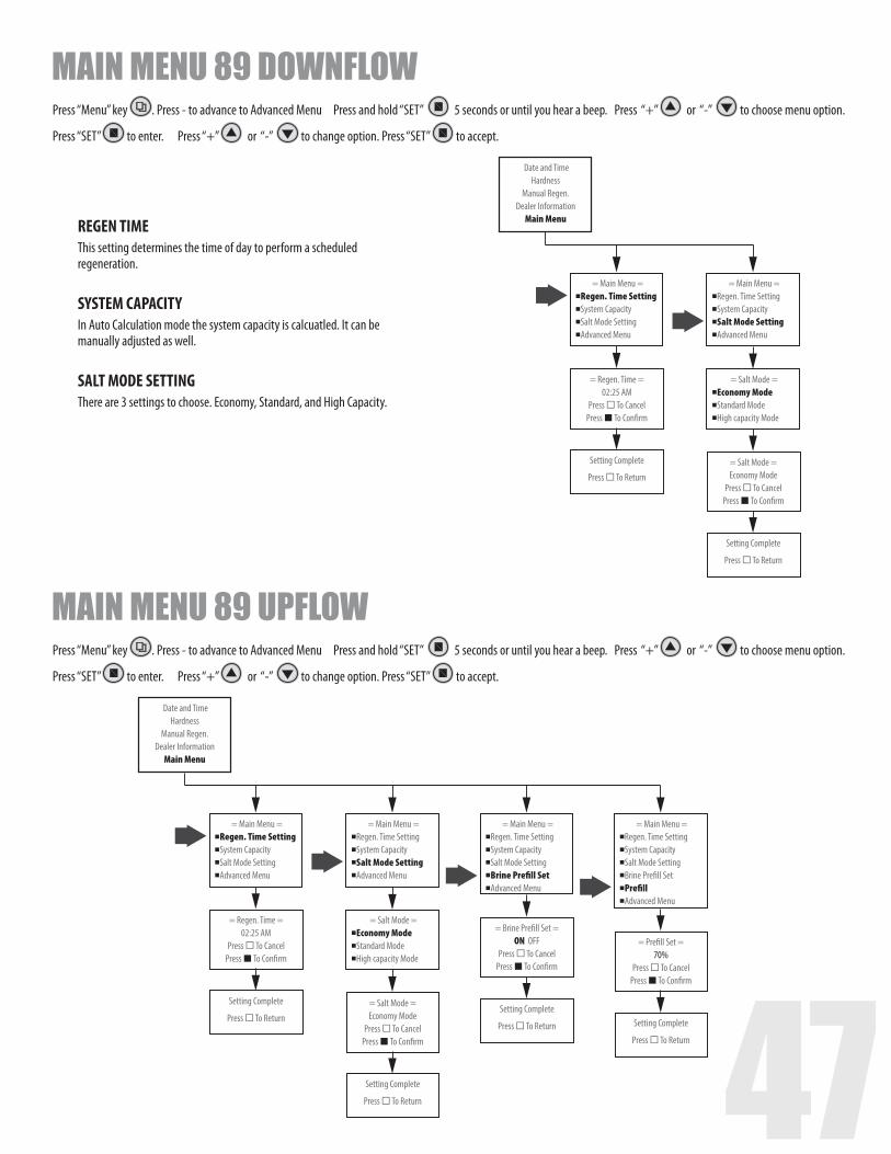
46 47
= Main Menu =Regen. Time SettingSystem CapacitySalt Mode SettingAdvanced Menu
Date and TimeHardness
Manual Regen.Dealer Information
Main Menu
= Regen. Time =02:25 AM
Press To CancelPress To Con�rm
Setting Complete
Press To Return
= Main Menu =Regen. Time SettingSystem CapacitySalt Mode SettingAdvanced Menu
= Salt Mode =Economy ModeStandard ModeHigh capacity Mode
= Salt Mode =Economy Mode
Press To CancelPress To Con�rm
Setting Complete
Press To Return
= Main Menu =Regen. Time SettingSystem CapacitySalt Mode SettingAdvanced Menu
Date and TimeHardness
Manual Regen.Dealer Information
Main Menu
= Regen. Time =02:25 AM
Press To CancelPress To Con�rm
Setting Complete
Press To Return
= Main Menu =Regen. Time SettingSystem CapacitySalt Mode SettingAdvanced Menu
= Salt Mode =Economy ModeStandard ModeHigh capacity Mode
= Salt Mode =Economy Mode
Press To CancelPress To Con�rm
Setting Complete
Press To Return
= Main Menu =Regen. Time SettingSystem CapacitySalt Mode SettingBrine Pre�ll SetAdvanced Menu
= Brine Pre�ll Set =ON OFF
Press To CancelPress To Con�rm
Setting Complete
Press To Return
= Main Menu =Regen. Time SettingSystem CapacitySalt Mode SettingBrine Pre�ll SetPre�llAdvanced Menu
= Pre�ll Set =70%
Press To CancelPress To Con�rm
Setting Complete
Press To Return
MAIN MENU 89 DOWNFLOW
MAIN MENU 89 UPFLOW
REGEN TIME This setting determines the time of day to perform a scheduled regeneration. SYSTEM CAPACITYIn Auto Calculation mode the system capacity is calcuatled. It can be manually adjusted as well. SALT MODE SETTINGThere are 3 settings to choose. Economy, Standard, and High Capacity.
Press “Menu” key . Press - to advance to Advanced Menu Press and hold “SET” 5 seconds or until you hear a beep. Press “+” or “-” to choose menu option.
Press “SET” to enter. Press “+” or “-” to change option. Press “SET” to accept.
Press “Menu” key . Press - to advance to Advanced Menu Press and hold “SET” 5 seconds or until you hear a beep. Press “+” or “-” to choose menu option.
Press “SET” to enter. Press “+” or “-” to change option. Press “SET” to accept.
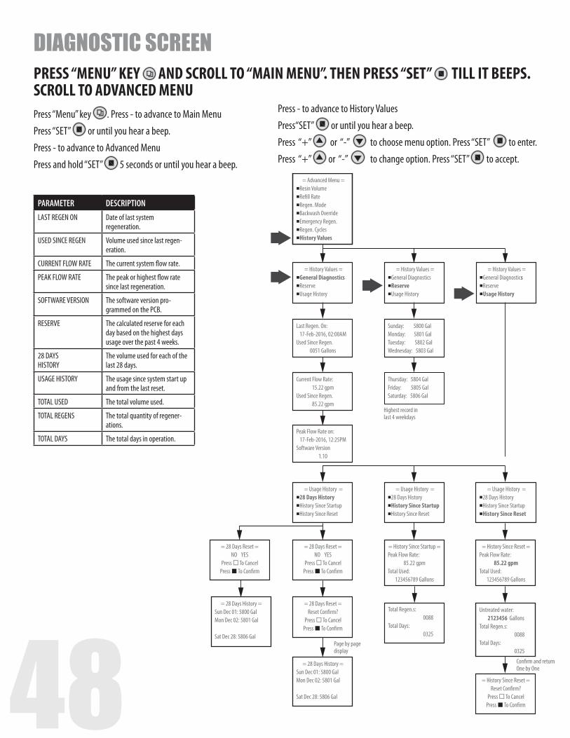
48
= Advanced Menu =Resin VolumeRe�ll RateRegen. ModeBackwash OverrideEmergency Regen.Regen. CyclesHistory Values
= History Values =General DiagnosticsReserveUsage History
= Usage History =28 Days HistoryHistory Since StartupHistory Since Reset
= Usage History =28 Days HistoryHistory Since StartupHistory Since Reset
= Usage History =28 Days HistoryHistory Since StartupHistory Since Reset
= History Values =General DiagnosticsReserveUsage History
= History Values =General DiagnosticsReserveUsage History
= 28 Days Reset =NO YES
Press To CancelPress To Con�rm
= History Since Startup = Peak Flow Rate:
85.22 gpm Total Used:
123456789 Gallons
= History Since Reset = Peak Flow Rate:
85.22 gpm Total Used:
123456789 Gallons
= 28 Days Reset =Reset Con�rm?
Press To CancelPress To Con�rm
= History Since Reset =Reset Con�rm?
Press To CancelPress To Con�rm
Total Regen.s: 0088 Total Days: 0325
= 28 Days History = Sun Dec 01: 5800 Gal Mon Dec 02: 5801 Gal Sat Dec 28: 5806 Gal
= 28 Days History = Sun Dec 01: 5800 Gal Mon Dec 02: 5801 Gal Sat Dec 28: 5806 Gal
= 28 Days Reset =NO YES
Press To CancelPress To Con�rm
Untreated water:2123456 Gallons
Total Regen.s: 0088 Total Days: 0325
Last Regen. On:17-Feb-2016, 02:00AM
Used Since Regen.0051 Gallons
Sunday: 5800 Gal Monday: 5801 Gal Tuesday: 5802 Gal Wednesday: 5803 Gal
Current Flow Rate:15.22 gpm
Used Since Regen.85.22 gpm
Thursday: 5804 Gal Friday: 5805 Gal Saturday: 5806 Gal
Peak Flow Rate on:17-Feb-2016, 12:25PM
Software Version1.10
Highest record inlast 4 weekdays
Page by page display
Con�rm and returnOne by One
PARAMETER DESCRIPTIONLAST REGEN ON Date of last system
regeneration.
USED SINCE REGEN Volume used since last regen-eration.
CURRENT FLOW RATE The current system flow rate.
PEAK FLOW RATE The peak or highest flow rate since last regeneration.
SOFTWARE VERSION The software version pro-grammed on the PCB.
RESERVE The calculated reserve for each day based on the highest days usage over the past 4 weeks.
28 DAYS HISTORY
The volume used for each of the last 28 days.
USAGE HISTORY The usage since system start up and from the last reset.
TOTAL USED The total volume used.
TOTAL REGENS The total quantity of regener-ations.
TOTAL DAYS The total days in operation.
PRESS “MENU” KEY AND SCROLL TO “MAIN MENU”. THEN PRESS “SET” TILL IT BEEPS. SCROLL TO ADVANCED MENU
DIAGNOSTIC SCREEN
Press “Menu” key . Press - to advance to Main Menu
Press “SET” or until you hear a beep.
Press - to advance to Advanced Menu
Press and hold “SET” 5 seconds or until you hear a beep.
Press - to advance to History Values
Press“SET” or until you hear a beep.
Press “+” or “-” to choose menu option. Press “SET” to enter.
Press “+” or “-” to change option. Press “SET” to accept.
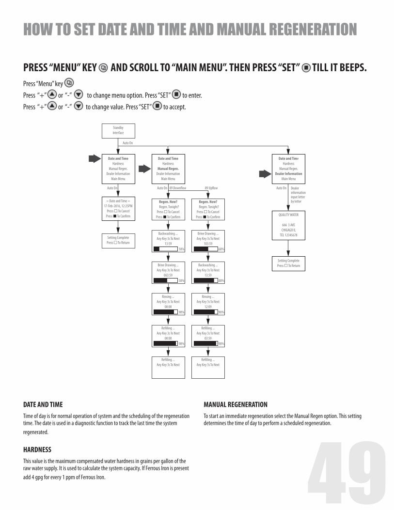
48 49
Date and TimeHardness
Manual Regen.Dealer Information
Main Menu
Regen. Now?Regen. Tonight?
Press To CancelPress To Con�rm
Backwashing ...Any Key 3s To Next
13:59
89 Down�ow 89 Up�owAuto On
18%
Brine Drawing ...Any Key 3s To Next
063:5950%
Rinsing ...Any Key 3s To Next
00:0090%
Re�lling ...Any Key 3s To Next
00:0098%
Re�lling ...Any Key 3s To Next
Regen. Now?Regen. Tonight?
Press To CancelPress To Con�rm
Brine Drawing ...Any Key 3s To Next
103:5968%
Backwashing ...Any Key 3s To Next
13:5988%
Rinsing ...Any Key 3s To Next
12:0990%
Re�lling ...Any Key 3s To Next
03:5998%
Re�lling ...Any Key 3s To Next
Date and TimeHardness
Manual Regen.Dealer Information
Main Menu
QUALITY WATER
666 3 AVECHIGAGO IL
TEL 12345678
Setting CompletePress To Return
Date and TimeHardness
Manual Regen.Dealer Information
Main Menu
= Date and Time =17-Feb-2016, 12:25PM
Press To CancelPress To Con�rm
Setting CompletePress To Return
Standby interface
Auto On
Auto On
Auto On Dealer informationinput letter by letter
PRESS “MENU” KEY AND SCROLL TO “MAIN MENU”. THEN PRESS “SET” TILL IT BEEPS.
HOW TO SET DATE AND TIME AND MANUAL REGENERATION
Press “Menu” key
Press “+” or “-” to change menu option. Press “SET” to enter.
Press “+” or “-” to change value. Press “SET” to accept.
DATE AND TIMETime of day is for normal operation of system and the scheduling of the regeneration time. The date is used in a diagnostic function to track the last time the systemregenerated.
HARDNESSThis value is the maximum compensated water hardness in grains per gallon of the raw water supply. It is used to calculate the system capacity. If Ferrous Iron is present add 4 gpg for every 1 ppm of Ferrous Iron.
MANUAL REGENERATIONTo start an immediate regeneration select the Manual Regen option. This setting determines the time of day to perform a scheduled regeneration.
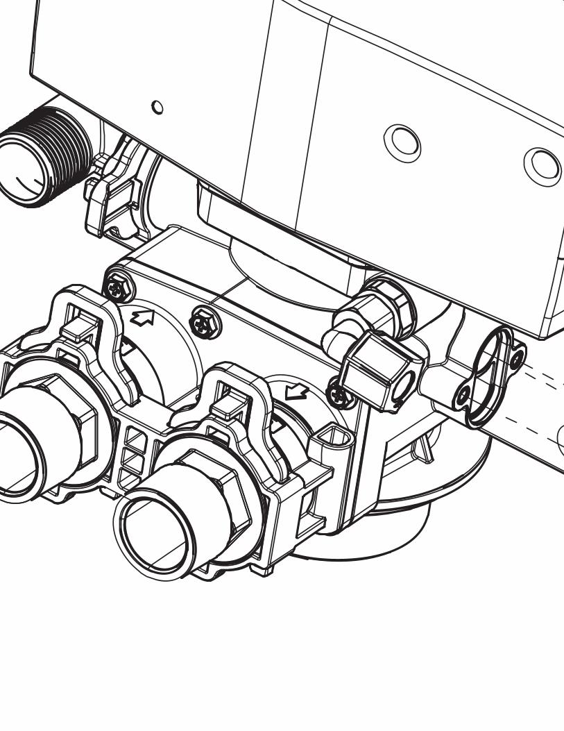
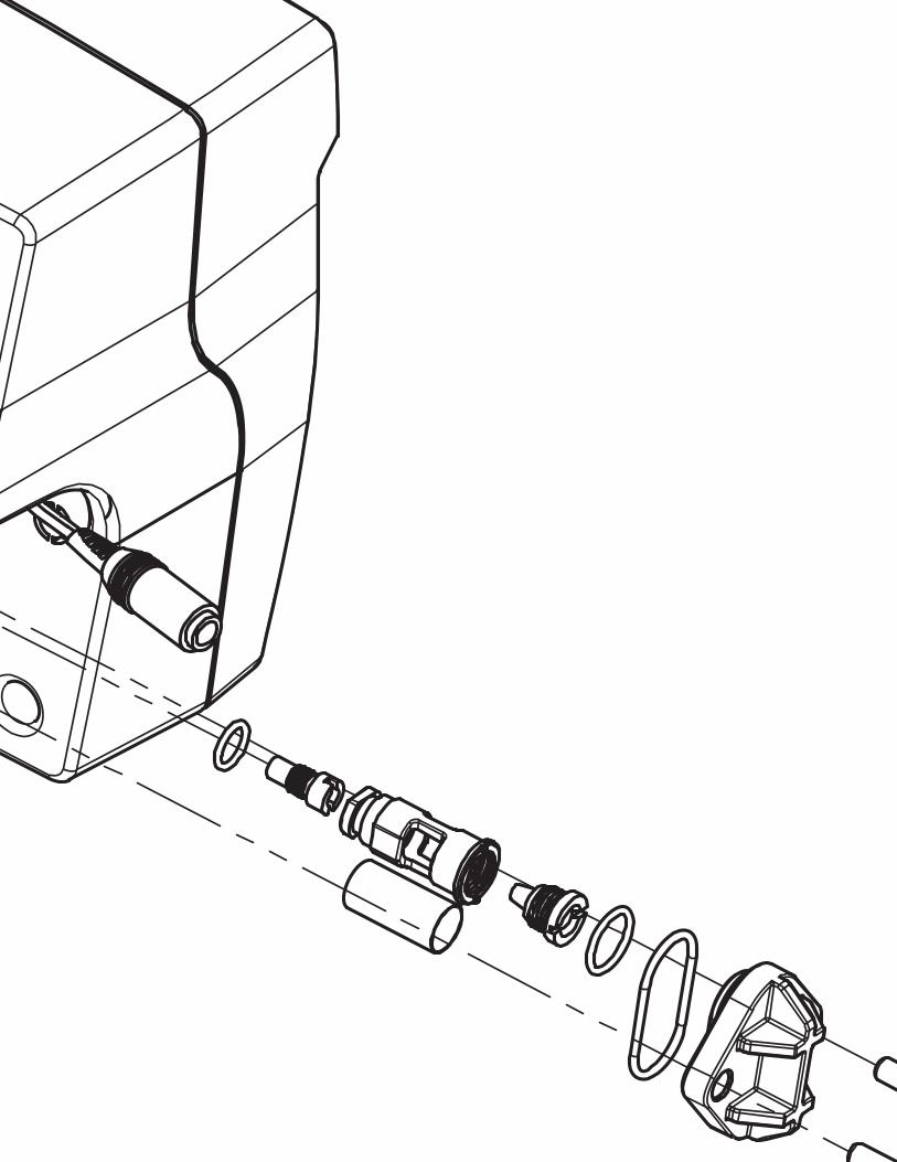
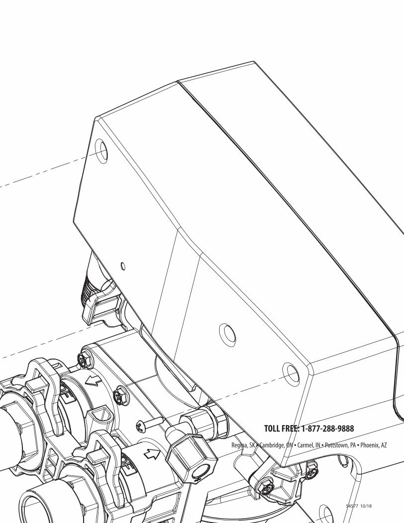
54577 10/18
TOLL FREE: 1-877-288-9888
Regina, SK • Cambridge, ON • Carmel, IN • Pottstown, PA • Phoenix, AZ