5 hazards hazardous areas and equipments docx (1) (repaired)
DESCRIPTION
For engineers in oil and gas field, this paper will help in understanding the basics of hazards, hazardous areas and zones, area classification and equipment for hydro carbon/oil and gas field Comments and corrections freely invited for improvementTRANSCRIPT
The most widely used world
HAZARDS,HAZARDOUS AREAS AND EQUIPMENTS
FOR HYDRO-CARBON AND OIL & GAS FIELDS
O N G C L T D . ,
W E L L S E R V I C E S , C A U V E R Y
A S S E T , K A R A I K K A L , C W # 8 -
W . O . R
S . V E N K A T A R A M A N , A . E . E .
( E L E C T )
9 4 4 2 5 9 3 3 6 2
E - M A I L - s v e n k u 6 4 @ g m a i l . c o m
S. VENKATARAMAN
THIS DOCUMENT/MATERIAL/ASSIGNMENT DEALS WITH
THE BASICS ON THE CLASSIFICATION OF HAZARDOUS
AREAS, ZONES AND ELECTRICAL EQUIPMENTS FOR OIL
AND GAS FIELDS. THE CONTENTS ARE TAKEN FROM
VARIOUS INTERNET ANND TRAINING MATERIALS AND
EDITED TO MAKE THE TOPIC EASILY UNDERSTANDABLE
FOR ANYONE WITH SUITABLE REFERENCES AND
INCORPORATIONS FROM OMR 1984, CEA REGULATIONS
2010 AND OISD GUIDELINES AND STANDARDS.
COMMENTS AND SUGGESTIONS ARE FREELY INVITED TO
MAKE THE BOOK MORE INFORMATIVE AND USEFUL. FOR
ONGCIANS AND OFFICERS IN OIL AND GAS FIELDS.
1
REFERENCES
1. API RP 500 & 505
2. O.M.R.1984
3. C.E.A. REGULATIONS 2010
4. O.I.S.D STDs, GDNs and RPs
5. TRAINING MATERIALS FROM CIMFL, DHANBAD
6. TRAINING MATERIALS FROM BHEL, BHOPAL
7. AND OTHER INTERNET SOURCES
2
INDEX
SECTION-1-COMPOSITION OF AIR
SECTION-2-CLASSIFICATION OF GASES
SECTION 3-FLAMMABLE GASES
SECTION-4-FIRE HAZARDS
SECTION-5-CLASSIFICATION OF HAZARDOUS AREAS
SECTION-6-OTHER TERMS AND CRITERIA (ON HAZARDOUS AREAS)
SECTION-7-NFPA704 DIAMOND OR FIRE DIAMOND
SECTION-8-GROUPING OF MOTORS AND EQUIPMENTS
SECTION-9-CONCEPTS OF EX-HAZARDOUS EQUIPMENTS
SECTION-10-INGRESS PROTECTION
SECTION-11-UNDERSTANDING EX-EQUIPMENT NAME PLATE DETAILS
SECTION-12- DEFINING HAZARDOUS AREAS AND ZONE EXTENT
3
4
5
6
INTRODUCTION
THE PRESENCE OF EXPLOSIVE GASES VAPOURS AND COMBUSTIBLE DUST IN
THE LOCATIONS, WHERE PRODUCTION, PROCESSING OR HANDLING OF THE
CHEMICAL PRODUCTS IS A ROUTINE WORK, MAY CREATE POTENTIALLY
EXPLOSIVE AREAS. THESE EXPLOSIVE AREAS ARE KNOWN AND DEFINED AS
HAZARDOUS LOCATIONS AND CLASSIFIED AS ZONES/ DIVISIONS. THIS PAPER
DEALS WITH CLASSIFICATION OF SUCH AREAS UNDER DIFFERENT SYSTEMS
WORLDWIDE. THERE ARE TWO MAIN FACTORS WHICH ARE RESPONSIBLE FOR
EXPLOSION:
(1)EXPLOSIVE ATMOSPHERE AND (2) SOURCE OF IGNITION.
THE FIRST STRATEGY FOR PREVENTION OF EXPLOSION IS TO TAKE ALL
PRECAUTIONS SO THAT AN EXPLOSIVE ENVIRONMENT IS NOT CREATED. BUT
IT IS NOT POSSIBLE IN THE INDUSTRIES WHERE GASES ARE EMITTED DURING
THE PROCESS OF PRODUCTION, REFINING AND STORAGE. THEREFORE IT IS
NECESSARY TO PREVENT THE SOURCE OF IGNITION IN THE POTENTIALLY
EXPLOSIVE ATMOSPHERE. THERE MAY BE VARIOUS METHODS BY WHICH WE
CAN DO.
7
SECTION-1
COMPOSITION OF AIR
8
SECTION -1
COMPOSITION OF AIR
INTRODUCTION: - Most of the time, we take air for granted. We breathe it with very little conscious thought. We use it to burn fuels, transportation, power generation, and many other purposes. What is air? What is air made up of? What are the useful products directly produced from the air?
AIR: - Air is the name given to the mixture of gases which make up the atmosphere. The composition, physical and chemical properties of air are very similar everywhere. CHEMICAL COMPOSITION IOF AIR: - The air is a naturally produced mixture of three types of ingredients, as follows,
• Standard dry air • Water vapor and • Other constituents
1. Standard Dry Air: - This mainly consists of three gases, mainly • Nitrogen • Oxygen • Argon and • Other gases in small percentages / in PPM
Together nitrogen, oxygen and argon make up for 99.96% of earth’s atmosphere. All these three gases can be economically recovered as industrial gas products. The dry air also consists of very small % of (or in PPM) CO2, neon, helium, Krypton, hydrogen and xenon. 2. Water vapor / humidity: - The amount of water vapor in the air at ground level can vary from almost 0% to 5%. Many factors influence the amount of humidity in the air at given time and location. 3. Other Constituents: - These are usually present in traceable quantities which reflect the local condition
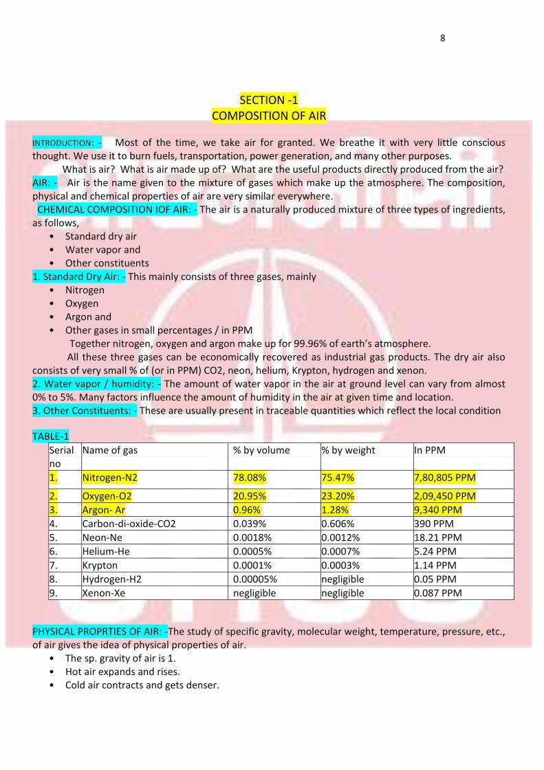
TABLE-1
In PPM % by weight % by volume Name of gas Serial no
7,80,805 PPM 75.47% 78.08% Nitrogen-N2 1.
2,09,450 PPM 23.20% 20.95% Oxygen-O2 2.
9,340 PPM 1.28% 0.96% Argon- Ar 3.
390 PPM 0.606% 0.039% Carbon-di-oxide-CO2 4.
18.21 PPM 0.0012% 0.0018% Neon-Ne 5.
5.24 PPM 0.0007% 0.0005% Helium-He 6.
1.14 PPM 0.0003% 0.0001% Krypton 7.
0.05 PPM negligible 0.00005% Hydrogen-H2 8.
0.087 PPM negligible negligible Xenon-Xe 9.
PHYSICAL PROPRTIES OF AIR: -The study of specific gravity, molecular weight, temperature, pressure, etc., of air gives the idea of physical properties of air.
• The sp. gravity of air is 1. • Hot air expands and rises. • Cold air contracts and gets denser.
9
• High temperature in the atmosphere means high barometric pressure with high % of water vapor and clear sky.
• Low temperature in the atmosphere means low barometric pressure with low % of water vapor and it is associated with cloudy skies and rain.
• When the temperature increases, so does the water vapor and the density is less than the air. • The difference in density leads to fluctuations in barometric pressure and consequently weather
conditions. • And the higher the altitude the lower the temperature of the air and the density is more
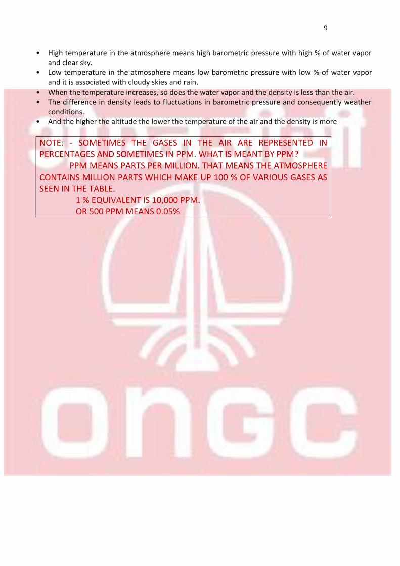
NOTE: - SOMETIMES THE GASES IN THE AIR ARE REPRESENTED IN PERCENTAGES AND SOMETIMES IN PPM. WHAT IS MEANT BY PPM? PPM MEANS PARTS PER MILLION. THAT MEANS THE ATMOSPHERE CONTAINS MILLION PARTS WHICH MAKE UP 100 % OF VARIOUS GASES AS SEEN IN THE TABLE. 1 % EQUIVALENT IS 10,000 PPM. OR 500 PPM MEANS 0.05%
10
SECTION-2
CLASSIFICATION OF GASES
11
SECTION-2.1
CLASSIFICATION OF GASES
CLASSIFICATION OF GASES: - Gases can be broadly classified into two categories, as follows. • As per their reactivity with other materials/gases. • As per their pressure and temperature conditions.
AS PER REACTIVITY: -As per the reactivity of the gases, the gases are divided into three categories, as
given below. • Oxidizers or reactive gases. • Inert gases and • Flammable gases.
1. OXIDIZERS OR REACTIVE GASES: - Oxidizing gases are not flammable by themselves, but they contribute to the flammability. Some of the oxidizing gases are: Oxygen, Air, Chlorine, Fluorine, Nitrogen oxide, etc
2. INERT GASES: - Inert gases do not take part in combustion and they do not react with other materials or gases. Inert gases generally consist of less than 8% oxygen by volume and they limit or control the combustion process. Inert gases are used in fire extinguishing systems where it is important to avoid water damage and rooms with electronic devices. Some of the inert gases are: Argon, Helium, Neon, Nitrogen, Krypton, Xenon, etc
3. FLAMMABLE GASES: - The flammable gases are the gases that burn or explode, if ignited, when mixed with air in appropriate proportion. Some examples are: Natural gas, methane, propane. hydrogen, acetylene.
SECTION 2.2
AS PER TEMPERATURE AND PRESSURE CONDITIONS:- The gases can be divided into four
categories, as following. • At normal pressure and temperature: The gas remains at it is at its normal temperature and
pressure. Some examples are: - Oxygen, nitrogen, etc. in the air
• At normal temperature but increased pressure: The gas remains liquefied at normal temperature but increased pressure. Example: LPG.
• Gases that cannot be pressurized or heated: The gases that explode if heated to higher temperature or pressurized. Example: Acetylene.
• Cryogenic gases: The gases that are cooled to -200 degree Celsius or more to make the gas liquefied. Some examples are: Liquid Nitrogen (LN2), Liquid Oxygen (LO2)
Advantages of cryogenic gases: • More resistance to wear. • Frozen food. Bulk quantities of food items can be transported and stored for a long time. • Blood banking.
12
• Transportation. At cryogenic temperatures the gas requires only 1/600th of space that is required for a gas at normal pressure and temperature. Hence very large quantities of gas can be transported from one country to another country.
OTHER FORMS OF GASES
NOBLE GAS: Noble gases are elemental, but inert gases are not elemental and are often compound gases. Noble gases have full valence electron shells. Atoms with full valence electron shells are extremely stable and therefore do not tend to form chemical bonds and have little tendency to gain or lose electrons.
GREENHOUSE GASES: Greenhouse gases are the gases that absorb or emit radiation within the thermal infrared range. Some examples are: CO2, Methane.
13
SECTION 3
FLAMMABLE GASES
14
SECTION-3
FLAMMABLE GASES (References from miscellaneous internet sources and Wikipedia)
FLAMMABLE GASES: The flammable gases are the gases that burn or explode, if ignited, when mixed with air in appropriate proportion. For a better understanding of flammable gases/liquids and their hazards, the knowledge of
• The type of hazard (whether group I/II/III or class I/II/III) • The likelihood of hazard (zone0/zone1/zone2), • LEL, HEL and flammability range, • Flammability class • Temperature class, • Ignition pressure, • Ignition energy, • Ignition temperature, • Stoichiometric quantity, of a particular flammable gas/oil, is necessary and this will give an idea,
for the people working in hydrocarbon or petroleum handling plants and industries, on how to reduce the chances of fire.
MOST COMMON CAUSES OF FIRE: Some common risks involved with chemical, petro-chemical, petroleum or hydro-carbon plants are:
• Toxic risk and • Fire risk
Fire risks are generally caused by the following factors: • Ignition temperature of the particular gas/vapor being dealt with in the plant (The ignition
temperature of the gas must be well known and it should be higher than the maximum temperature of apparatus, cables, etc.)
• Static electricity discharge • Lightning and electromagnetic radiation • Incendiary energy due to hot works like welding, etc., • Open flames • Arcs and sparks due to short circuits in motors and cables, etc.,
INERT GAS BLANKETING: In bulk oil tankers, cargo tankers and bunkers inert gas is filled before filling hydro-carbon gas/oil to prevent the atmosphere in them from coming into explosive or flammable range. Inert gas keeps the oxygen content in the tank below 8 %, thus making the air and hydro-carbon mixture in the tank very weak to be ignited and thus preventing fire and explosion. NOTE: Inert gas is generated on board crude oil tankers by using either a flue gas system or by using an inert gas generator. The most common method is by using inert gas generator, which consists of a combustion chamber, scrubber unit with fans, cooling system and a drier.
15
SECTION-4
FIRE HAZARDS
16
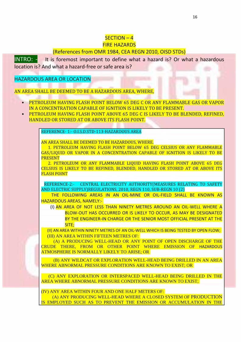
SECTION – 4
FIRE HAZARDS (References from OMR 1984, CEA REGN 2010, OISD STDs)
INTRO: - It is foremost important to define what a hazard is? Or what a hazardous
location is? And what a hazard-free or safe area is?
HAZARDOUS AREA OR LOCATION AN AREA SHALL BE DEEMED TO BE A HAZARDOUS AREA, WHERE,
• PETROLEUM HAVING FLASH POINT BELOW 65 DEG C OR ANY FLAMMABLE GAS OR VAPOR IN A CONCENTRATION CAPABLE OF IGNITION IS LIKELY TO BE PRESENT.
• PETROLEUM HAVING FLASH POINT ABOVE 65 DEG C IS LIKELY TO BE BLENDED, REFINED, HANDLED OR STORED AT OR ABOVE ITS FLASH POINT.
REFERENCE- 1:- O.I.S.D.STD-113-HAZARDOUS AREA AN AREA SHALL BE DEEMED TO BE HAZARDOUS, WHERE. 1. PETROLEUM HAVING FLASH POINT BELOW 65 DEG CELSIUS OR ANY FLAMMABLE GAS/LIQUID OR VAPOR IN A CONCENTRATION CAPABLE OF IGNITION IS LIKELY TO BE PRESENT 2. PETROLEUM OR ANY FLAMMABLE LIQUID HAVING FLASH POINT ABOVE 65 DEG CELSIUS IS LIKELY TO BE REFINED, BLENDED, HANDLED OR STORED AT OR ABOVE ITS FLASH POINT REFERENCE-2:- CENTRAL ELECTRICITY AUTHORITY(MEASURES RELATING TO SAFETY AND ELECTRIC SUPPLY)REGULATIONS, 2010, REGN 110, SUB-REGN 10 (2)
THE FOLLOWING AREAS IN AN OIL-MINE OR OIL-FIELD SHALL BE KNOWN AS HAZARDOUS AREAS, NAMELY:-
(I) AN AREA OF NOT LESS THAN NINETY METRES AROUND AN OIL-WELL WHERE A BLOW-OUT HAS OCCURRED OR IS LIKELY TO OCCUR, AS MAY BE DESIGNATED BY THE ENGINEER-IN CHARGE OR THE SENIOR MOST OFFICIAL PRESENT AT THE SITE;
(II) AN AREA WITHIN NINETY METRES OF AN OIL-WELL WHICH IS BEING TESTED BY OPEN FLOW;
(III) AN AREA WITHIN FIFTEEN METRES OF:
(A) A PRODUCING WELL-HEAD OR ANY POINT OF OPEN DISCHARGE OF THE
CRUDE THERE, FROM OR OTHER POINT WHERE EMISSION OF HAZARDOUS
ATMOSPHERE IS NORMALLY LIKELY TO ARISE; OR
(B) ANY WILDCAT OR EXPLORATION WELL-HEAD BEING DRILLED IN AN AREA
WHERE ABNORMAL PRESSURE CONDITIONS ARE KNOWN TO EXIST; OR (C) ANY EXPLORATION OR INTERSPACED WELL-HEAD BEING DRILLED IN THE
AREA WHERE ABNORMAL PRESSURE CONDITIONS ARE KNOWN TO EXIST;
(IV) ANY AREA WITHIN FOUR AND ONE HALF METERS OF:
(A) ANY PRODUCING WELL-HEAD WHERE A CLOSED SYSTEM OF PRODUCTION IS EMPLOYED SUCH AS TO PREVENT THE EMISSION OR ACCUMULATION IN THE
17
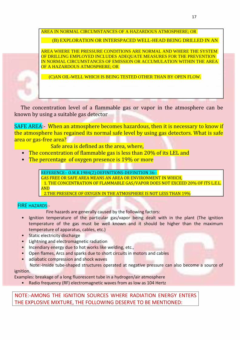
AREA IN NORMAL CIRCUMSTANCES OF A HAZARDOUS ATMOSPHERE; OR
(B) EXPLORATION OR INTERSPACED WELL-HEAD BEING DRILLED IN AN
AREA WHERE THE PRESSURE CONDITIONS ARE NORMAL AND WHERE THE SYSTEM
OF DRILLING EMPLOYED INCLUDES ADEQUATE MEASURES FOR THE PREVENTION
IN NORMAL CIRCUMSTANCES OF EMISSION OR ACCUMULATION WITHIN THE AREA
OF A HAZARDOUS ATMOSPHERE; OR
(C)AN OIL-WELL WHICH IS BEING TESTED OTHER THAN BY OPEN FLOW.
The concentration level of a flammable gas or vapor in the atmosphere can be known by using a suitable gas detector
SAFE AREA:- When an atmosphere becomes hazardous, then it is necessary to know if the atmosphere has regained its normal safe level by using gas detectors. What is safe area or gas-free area?
Safe area is defined as the area, where, • The concentration of flammable gas is less than 20% of its LEL and • The percentage of oxygen presence is 19% or more
REFERENCE:- O.M.R.1984(2):DEFINITIONS-DEFINITION 36:- GAS FREE OR SAFE AREA MEANS AN AREA OR ENVIRONMENT IN WHICH, 1. THE CONCENTRATION OF FLAMMABLE GAS/VAPOR DOES NOT EXCEED 20% OF ITS L.E.L. AND
2.THE PRESENCE OF OXYGEN IN THE ATMOSPHERE IS NOT LESS THAN 19%
FIRE HAZARDS:-
Fire hazards are generally caused by the following factors: • Ignition temperature of the particular gas/vapor being dealt with in the plant (The ignition
temperature of the gas must be well known and it should be higher than the maximum temperature of apparatus, cables, etc.)
• Static electricity discharge • Lightning and electromagnetic radiation • Incendiary energy due to hot works like welding, etc., • Open flames, Arcs and sparks due to short circuits in motors and cables • adiabatic compression and shock waves
Note:-Inside tube-shaped structures operated at negative pressure can also become a source of ignition. Examples: breakage of a long fluorescent tube in a hydrogen/air atmosphere
• Radio frequency (RF) electromagnetic waves from as low as 104 Hertz
NOTE:-AMONG THE IGNITION SOURCES WHERE RADIATION ENERGY ENTERS THE EXPLOSIVE MIXTURE, THE FOLLOWING DESERVE TO BE MENTIONED:
18
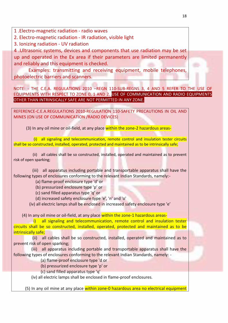
1 .Electro-magnetic radiation - radio waves 2. Electro-magnetic radiation - IR radiation, visible light 3. Ionizing radiation - UV radiation 4 .Ultrasonic systems, devices and components that use radiation may be set up and operated in the Ex area if their parameters are limited permanently and reliably and this equipment is checked. Examples: transmitting and receiving equipment, mobile telephones, photoelectric barriers and scanners. NOTE: - THE C.E.A. REGULATIONS 2010 –REGN 110-SUB-REGNS 3, 4 AND 5 REFER TO THE USE OF EQUIPMENTS WITH RESPECT TO ZONE 0, 1 AND 2. USE OF COMMUNICATION AND RADIO EQUIPMENTS OTHER THAN INTRINSICALLY SAFE ARE NOT PERMITTED IN ANY ZONE.
REFERENCE-C.E.A.REGULATIONS 2010-REGULATION 110-SAFETY PRECAUTIONS IN OIL AND MINES (ON USE OF COMMUNICATION /RADIO DEVICES) (3) In any oil mine or oil-field, at any place within the zone-2 hazardous areas- (i) all signaling and telecommunication, remote control and insulation tester circuits shall be so constructed, installed, operated, protected and maintained as to be intrinsically safe; (ii) all cables shall be so constructed, installed, operated and maintained as to prevent risk of open sparking;
(iii) all apparatus including portable and transportable apparatus shall have the following types of enclosures conforming to the relevant Indian Standards, namely:- (a) flame-proof enclosure type 'd' or (b) pressurized enclosure type 'p' or (c) sand filled apparatus type 'q' or (d) increased safety enclosure type 'e', 'n' and 'o' (iv) all electric lamps shall be enclosed in increased safety enclosure type 'e’ (4) In any oil mine or oil-field, at any place within the zone-1 hazardous areas- i) all signaling and telecommunication, remote control and insulation tester circuits shall be so constructed, installed, operated, protected and maintained as to be intrinsically safe; (ii) all cables shall be so constructed, installed, operated and maintained as to prevent risk of open sparking; (iii) all apparatus including portable and transportable apparatus shall have the following types of enclosures conforming to the relevant Indian Standards, namely: - (a) flame-proof enclosure type 'd or (b) pressurized enclosure type 'p' or (c) sand filled apparatus type ‘q' (iv) all electric lamps shall be enclosed in flame-proof enclosures. (5) In any oil mine at any place within zone-0 hazardous area no electrical equipment
19
shall be used and where it is not practicable, intrinsically safe apparatus are only to be used with the prior approval of the Inspector.
SECTION-5
CLASSIFICATION OF HAZARDOUS AREA
20
SECTION-5-
CLASSIFICATION OF HAZARDOUS AREA (References from CIMFR, Dhanbad lectures and print materials by A.K SINGH and R K.V)
INTRODUCTION
The presence of explosive gases, vapors and combustible dust in the locations where production, processing or handling of the chemical products is a routine work, may create potentially explosive areas. These explosive areas are known and defined as hazardous locations and classified as zones/ divisions. There are two main factors which are responsible for explosion: (1) Explosive atmosphere (COMBINATION OF FUEL AND AIR) and
(2) Source of ignition.
The first strategy for prevention of explosion is to take all precautions so that an explosive environment is not created. But it is not possible in the industries where gases are emitted during the process of production, refining and storage. Therefore it is necessary to prevent the source of ignition in the potentially explosive atmosphere. There may be various methods by which we can do. CRITERIA FOR CLASSIFICATION
The various methods for the prevention of fire depend largely upon the following factors, among other things, namely
• The type of hazard (whether group I/II/II or class I/II/III) • The likely hood of the hazard(whether zone I/II/III) and • Temperature class
SECTION-5.1
AREA CLASSIFICATION
AS PER THE TYPE OF HAZARD (References from CIMFR, Dhanbad print materials by Sri A. K.SINGH &Sri Vishwakarma)
TYPE OF HAZARD There are two major classifications prevalent worldwide
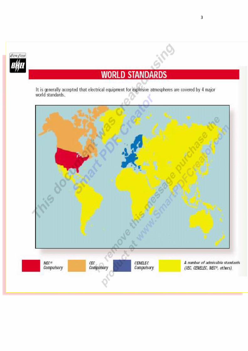
• As per NEC (National Electrical Code) of USA • As per IEC (International Electro technical Commission)- European and other
international countries including India NEC method is followed by America and American continental countries. MSHA (Mines Safety and Health Administration) separately covers and manages the mines and related safety matters in American continent. NEC covers and regulates surface installations other than mines in America.
NEC classifies the hazardous surface installations as under, • Class I hazardous area- Flammable gases, vapors and liquids • Class II hazardous area- Combustible dusts • Class III hazardous area-Combustible flyings and fibers
Class I hazardous area is again sub-divided into four categories as under
• CLASS I A- Acetylene (Extremely highly hazardous)
21
• CLASS I B- Hydrogen (highly hazardous) • CLASS I C- Ethylene (moderately hazardous) and • CLASS I D- Propane (hazardous)
Class I A is the highest degree of hazard and Class I D is the lowest degree of hazard and the degree of hazard of a particular gas/vapor or oil is determined according to the flammability or explosive range, flammability class, ignition energy, temperature and pressure, etc.,
Class II hazardous area is again sub-divided into three categories as,
• CLASS II E- Combustible metal dusts that are conductive and explosive • CLASS II F- Combustible carbon dusts that are explosive • CLASS II G- Grain dust like flour, other grain dusts and chemical dusts
Class III hazardous area relates to combustible flyings and fibers and this class has no sub-divisions
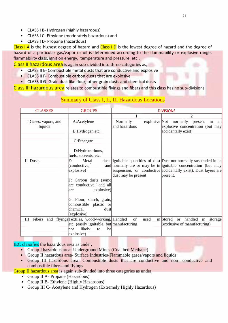
Summary of Class I, II, III Hazardous Locations
DIVISIONS GROUPS CLASSES
2 1 Not normally present in an
explosive concentration (but may
accidentally exist)
Normally explosive
and hazardous A:Acetylene
B:Hydrogen,etc.
C:Ether,etc.
D:Hydrocarbons,
fuels, solvents, etc.
I Gases, vapors, and
liquids
Dust not normally suspended in an
ignitable concentration (but may
accidentally exist). Dust layers are
present.
Ignitable quantities of dust
normally are or may be in
suspension, or conductive
dust may be present
E: Metal dusts
(conductive,* and
explosive)
F: Carbon dusts (some
are conductive,*
and all
are explosive)
G: Flour, starch, grain,
combustible plastic or
chemical dust
(explosive)
II Dusts
Stored or handled in storage
(exclusive of manufacturing) Handled or used in
manufacturing Textiles, wood-working,
etc. (easily ignitable, but
not likely to be
explosive)
III Fibers and flyings
IEC classifies the hazardous area as under,
• Group I hazardous area- Underground Mines (Coal bed Methane) • Group II hazardous area- Surface Industries-Flammable gases/vapors and liquids • Group III hazardous area- Combustible dusts that are conductive and non- conductive and
combustible fibers and flyings. Group II hazardous area is again sub-divided into three categories as under,
• Group II A- Propane (Hazardous) • Group II B- Ethylene (Highly Hazardous) • Group III C- Acetylene and Hydrogen (Extremely Highly Hazardous)
22
Group II C is the highest degree of hazard and Group II A is the lowest degree of hazard and the degree of hazard of a particular gas/vapor or oil is determined according to the flammability or explosive range, flammability class, ignition energy, temperature and pressure, etc., Group III hazardous area is also sub divided into three groups as under,
• Group III A- Combustible flyings • Group III B- Non-conductive dust like coal dust, grain dust, flour, etc., • Group III C- Conductive metal dusts from aluminum, copper, etc.,
NOTE- For conductive metal dusts, i.e., CLASS II E of NEC method or CLASS III C of IEC method, the
enclosures should be protected to IP 6 (Ingress Protection Degree 6). That is the enclosure should
be total or complete dust-proof.
SECTION 5.2
AREA CLASSIFICATION
AS PER THE LIKELYHOOD OF HAZARD (References from API-RP-500, NEC CODE 500)
AS PER THE LIKELY HOOD OF HAZARD the extent of hazard in a location is defined by divisions and zones
In class I(A, B, C and D) hazardous areas, that is in NEC method the extents are defined by,
Division I: The defined hazard is present during normal operational conditions
Division II:- The defined hazard is present only during abnormal conditions IN NEC method defining the divisions as I and II is same for both class I (gas/oil and liquid) and class II (dust) hazardous locations
In group II (A, B and C) hazardous areas, that is in IEC method, the extents are called zones and they are defined as
Zone 0:- Hazardous media is frequently present and may be present for long periods of time (>1000 hours per year) or even continuously and presence of gas/vapor is 10% or more than LEL
Zone 1: Hazardous media can exist under normal operating condition or hazardous atmosphere is possible but unlikely to be present for long periods of time (>10 <1000 hours per year) and the presence of gas/vapor is between 0.1% and 10% of LEL. Zone 2 : Hazardous media will exist only under abnormal circumstances due to accidental failures
hazardous atmosphere is not likely to be present in normal operation or infrequently and for short periods of time (<10 hours per year) and the presence of gas/vapor is between 0.01% and 0.1% of L.E.L
for 10 hours in a year.
In group III (B and C) classified areas that are dust explosion hazard areas, the zones are defined by. Zone 20: Hazardous dust media is always present
Zone 21: Hazardous dust media can be present during normal operating conditions and Zone 22: Hazardous dust media can exist under abnormal conditions
NOTE-1. ZONE 0 IS THE MOST HAZARDOUS EXTENT IN A LOCATION AND ZONE II IS THE LEAST HAZARDOUS EXTENT IN A LOCATION. 2. ZONE 0 GENERALLY EXISTS AND IS REFERRED TO IN ENCLOSED AND CONFINED PLACES AND NOT IN SURFACE AREAS OR INSTALLATIONS 3. GENERALLY, A DISTANCE OF 30 METERS AND AWAY FROM THE ZONE 0 OR ZONE 1 POINT IS CONSIDERED SAFE AREA, PROVIDED THERE ARE NO ABNORMAL CONDITIONS,
23
WITH 19% OR MORE OXYGEN AND LESS THAN 20% LEL
NOTE: IEC HAS SEPARATE CODES FOR COMBUSTIBLE DUST CLASSIFYING ZONES AS ZONE 20, 21 AND 22 SIMILAR IN EXTENT OF HAZARD AS IN ZONE 0, 1 AND 2 FOR GAS AND VAPORS.
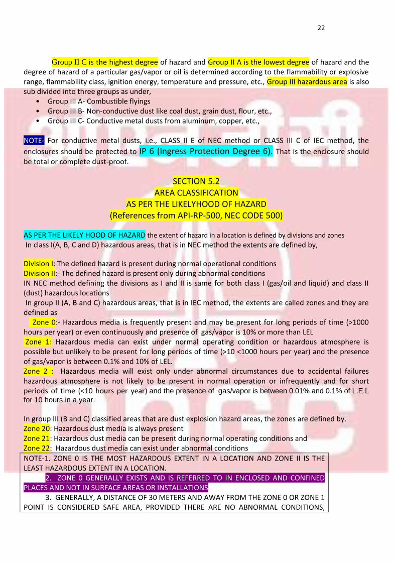
SUMMARY OF GROUP I, II and III HAZARDOUS LOCATIONS
MINING SURFACE INDUSTRIES
GROUP I GROUP II GROUP III
Electrical equipment for
mines susceptible to firedamp
Electrical equipment for places with an explosive gas atmosphere
Electrical equipment for places with an explosive dust atmosphere
Sub-division Sub-Division Ignition energy
II A III A 260 micro joules
II B III B 95 micro joules
III C II C 18 micro joules
SECTION 5.3 AREA CLASSIFICATION
AS PER TEMPERATURE CLASS
(References from CIMFR training and internet sources)
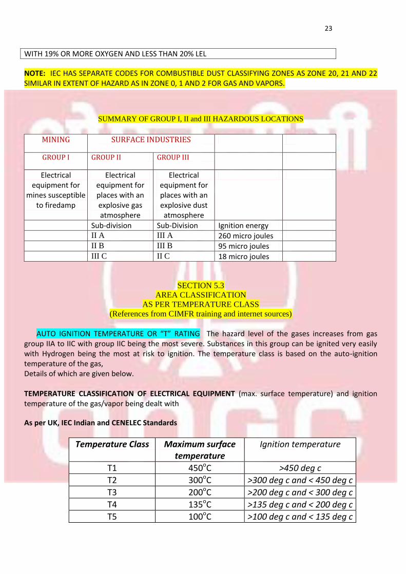
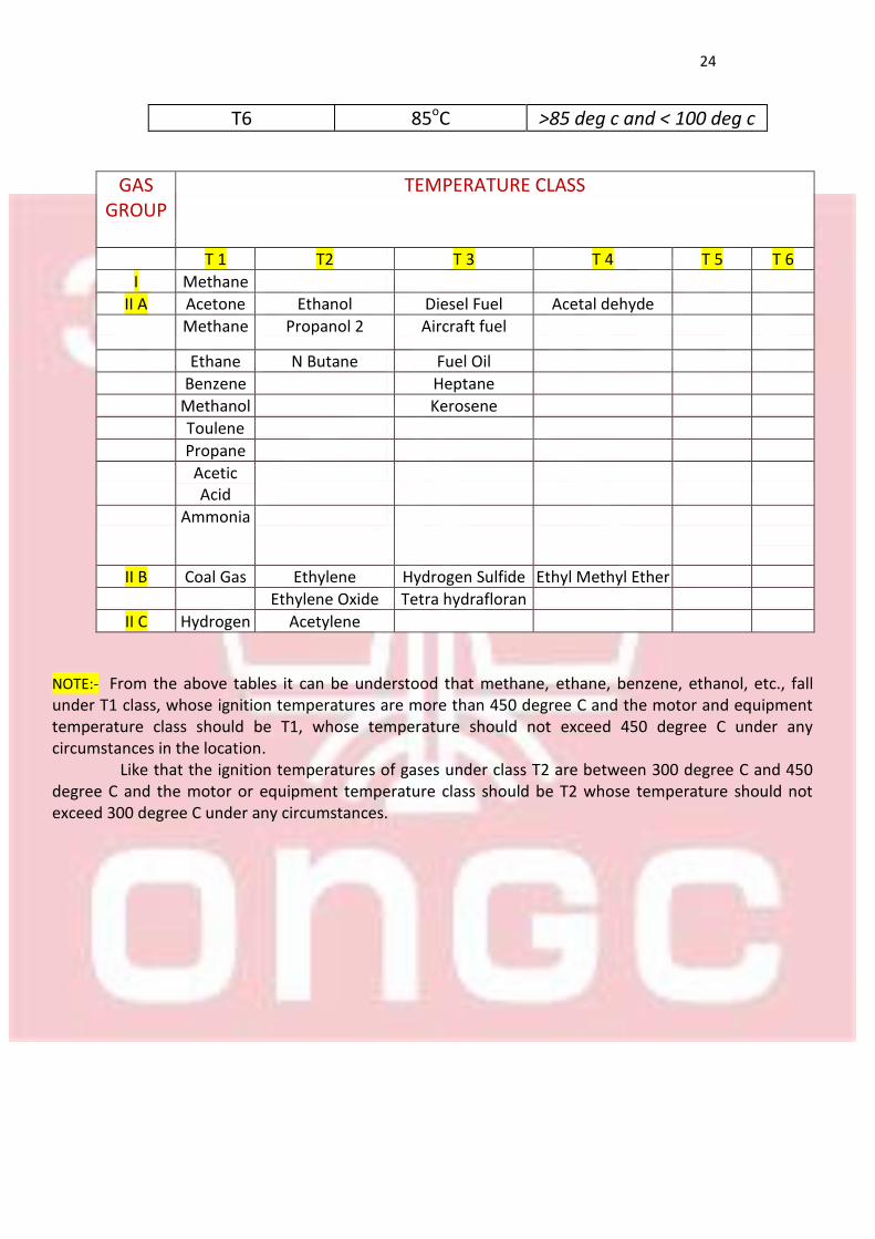
AUTO IGNITION TEMPERATURE OR “T” RATING The hazard level of the gases increases from gas group IIA to IIC with group IIC being the most severe. Substances in this group can be ignited very easily with Hydrogen being the most at risk to ignition. The temperature class is based on the auto-ignition temperature of the gas, Details of which are given below. TEMPERATURE CLASSIFICATION OF ELECTRICAL EQUIPMENT (max. surface temperature) and ignition temperature of the gas/vapor being dealt with
As per UK, IEC Indian and CENELEC Standards
Ignition temperature Maximum surface temperature
Temperature Class
>450 deg c 450oC T1
>300 deg c and < 450 deg c 300oC T2
>200 deg c and < 300 deg c 200oC T3
>135 deg c and < 200 deg c 135oC T4
>100 deg c and < 135 deg c 100oC T5
24
>85 deg c and < 100 deg c 85oC T6
TEMPERATURE CLASS GAS GROUP
T 6 T 5 T 4 T 3 T2 T 1
Methane I Acetal dehyde Diesel Fuel Ethanol Acetone II A
Aircraft fuel Propanol 2 Methane
Fuel Oil N Butane Ethane
Heptane Benzene
Kerosene Methanol
Toulene
Propane
Acetic Acid
Ammonia
Ethyl Methyl Ether Hydrogen Sulfide Ethylene Coal Gas II B
Tetra hydrafloran Ethylene Oxide
Acetylene Hydrogen II C
NOTE:- From the above tables it can be understood that methane, ethane, benzene, ethanol, etc., fall under T1 class, whose ignition temperatures are more than 450 degree C and the motor and equipment temperature class should be T1, whose temperature should not exceed 450 degree C under any circumstances in the location. Like that the ignition temperatures of gases under class T2 are between 300 degree C and 450 degree C and the motor or equipment temperature class should be T2 whose temperature should not exceed 300 degree C under any circumstances.
25
SECTION-6
OTHER HAZARDOUS TERMS AND CRITERIA
26
SECTION 6
OTHER HAZARDOUS TERMS AND CRITERIA
INTRO: Some other important terms and criteria related to hydro carbon field and hazardous locations are:
• LEL, HEL and Flammability or explosive range • Ignition Energy • Flammability Class among other things
SECTION 6.1
LEL, HEL AND EXPLOSIVE RANGE (References from CEA REGN 2010, OMR 1984 and IEC Ex, NEC 500 codes)
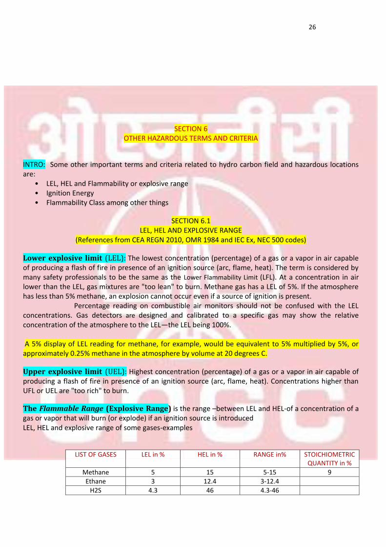
Lower explosive limit (LEL): The lowest concentration (percentage) of a gas or a vapor in air capable of producing a flash of fire in presence of an ignition source (arc, flame, heat). The term is considered by many safety professionals to be the same as the Lower Flammability Limit (LFL). At a concentration in air lower than the LEL, gas mixtures are "too lean" to burn. Methane gas has a LEL of 5%. If the atmosphere has less than 5% methane, an explosion cannot occur even if a source of ignition is present. Percentage reading on combustible air monitors should not be confused with the LEL concentrations. Gas detectors are designed and calibrated to a specific gas may show the relative concentration of the atmosphere to the LEL—the LEL being 100%. A 5% display of LEL reading for methane, for example, would be equivalent to 5% multiplied by 5%, or approximately 0.25% methane in the atmosphere by volume at 20 degrees C.
Upper explosive limit (UEL): Highest concentration (percentage) of a gas or a vapor in air capable of producing a flash of fire in presence of an ignition source (arc, flame, heat). Concentrations higher than UFL or UEL are "too rich" to burn. The Flammable Range (Explosive Range) is the range –between LEL and HEL-of a concentration of a gas or vapor that will burn (or explode) if an ignition source is introduced
LEL, HEL and explosive range of some gases-examples
STOICHIOMETRIC QUANTITY in %
RANGE in% HEL in % LEL in % LIST OF GASES
9 5-15 15 5 Methane
3-12.4 12.4 3 Ethane
4.3-46 46 4.3 H2S
27
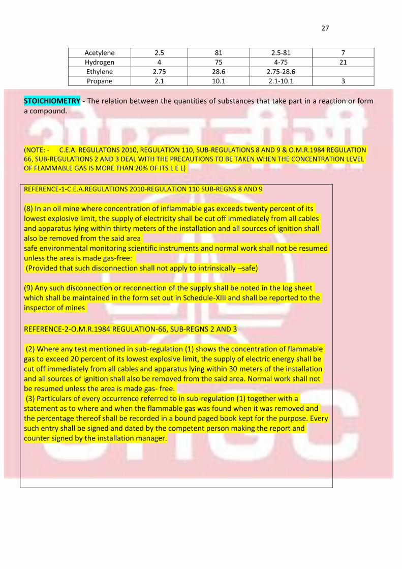
7 2.5-81 81 2.5 Acetylene
21 4-75 75 4 Hydrogen
2.75-28.6 28.6 2.75 Ethylene
3 2.1-10.1 10.1 2.1 Propane
STOICHIOMETRY - The relation between the quantities of substances that take part in a reaction or form a compound. (NOTE: - C.E.A. REGULATONS 2010, REGULATION 110, SUB-REGULATIONS 8 AND 9 & O.M.R.1984 REGULATION 66, SUB-REGULATIONS 2 AND 3 DEAL WITH THE PRECAUTIONS TO BE TAKEN WHEN THE CONCENTRATION LEVEL OF FLAMMABLE GAS IS MORE THAN 20% OF ITS L E L)
REFERENCE-1-C.E.A.REGULATIONS 2010-REGULATION 110 SUB-REGNS 8 AND 9
(8) In an oil mine where concentration of inflammable gas exceeds twenty percent of its lowest explosive limit, the supply of electricity shall be cut off immediately from all cables and apparatus lying within thirty meters of the installation and all sources of ignition shall also be removed from the said area safe environmental monitoring scientific instruments and normal work shall not be resumed unless the area is made gas-free: (Provided that such disconnection shall not apply to intrinsically –safe) (9) Any such disconnection or reconnection of the supply shall be noted in the log sheet which shall be maintained in the form set out in Schedule-XIII and shall be reported to the inspector of mines
REFERENCE-2-O.M.R.1984 REGULATION-66, SUB-REGNS 2 AND 3 (2) Where any test mentioned in sub-regulation (1) shows the concentration of flammable gas to exceed 20 percent of its lowest explosive limit, the supply of electric energy shall be cut off immediately from all cables and apparatus lying within 30 meters of the installation and all sources of ignition shall also be removed from the said area. Normal work shall not be resumed unless the area is made gas- free. (3) Particulars of every occurrence referred to in sub-regulation (1) together with a statement as to where and when the flammable gas was found when it was removed and the percentage thereof shall be recorded in a bound paged book kept for the purpose. Every such entry shall be signed and dated by the competent person making the report and counter signed by the installation manager.
28
SECTION 6.2
IGNITION ENERGY
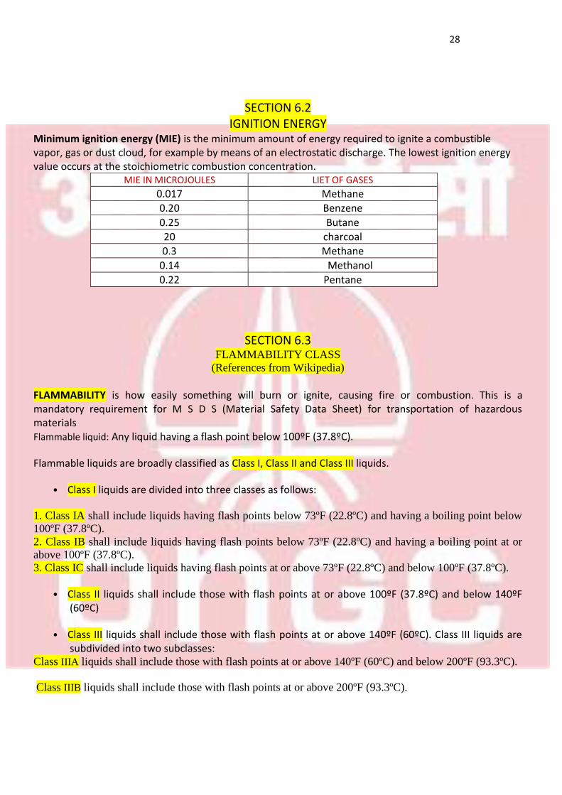
Minimum ignition energy (MIE) is the minimum amount of energy required to ignite a combustible vapor, gas or dust cloud, for example by means of an electrostatic discharge. The lowest ignition energy value occurs at the stoichiometric combustion concentration.
LIET OF GASES MIE IN MICROJOULES
Methane 0.017
Benzene 0.20
Butane 0.25
charcoal 20
Methane 0.3
Methanol 0.14
Pentane 0.22
SECTION 6.3
FLAMMABILITY CLASS
(References from Wikipedia)
FLAMMABILITY is how easily something will burn or ignite, causing fire or combustion. This is a mandatory requirement for M S D S (Material Safety Data Sheet) for transportation of hazardous materials
Flammable liquid: Any liquid having a flash point below 100ºF (37.8ºC).
Flammable liquids are broadly classified as Class I, Class II and Class III liquids.
• Class I liquids are divided into three classes as follows:
1. Class IA shall include liquids having flash points below 73ºF (22.8ºC) and having a boiling point below
100ºF (37.8ºC). 2. Class IB shall include liquids having flash points below 73ºF (22.8ºC) and having a boiling point at or
above 100ºF (37.8ºC). 3. Class IC shall include liquids having flash points at or above 73ºF (22.8ºC) and below 100ºF (37.8ºC).
• Class II liquids shall include those with flash points at or above 100ºF (37.8ºC) and below 140ºF (60ºC)
• Class III liquids shall include those with flash points at or above 140ºF (60ºC). Class III liquids are subdivided into two subclasses:
Class IIIA liquids shall include those with flash points at or above 140ºF (60ºC) and below 200ºF (93.3ºC).
Class IIIB liquids shall include those with flash points at or above 200ºF (93.3ºC).
29
NOTE: - WHILE THE GASES ARE CLASSIFIED AS GROUP I (MINES), GROUP II (SURFACE INDUSTRIES) AND GROUP III, THE LIQUIDS ARE CLASSIFIED AS CLASS I, CLASS II AND CLASS III WITH RESPECT TO THEIR DEGREES OF HAZARD
30
SECTION-7
N F P A 704 DIAMOND
OR FIRE DIAMOND
31
SECTION-7 NFPA 704 OR FIRE DIAMOND
(References from internet- NFPA 704 Diamond-Wikipedia)
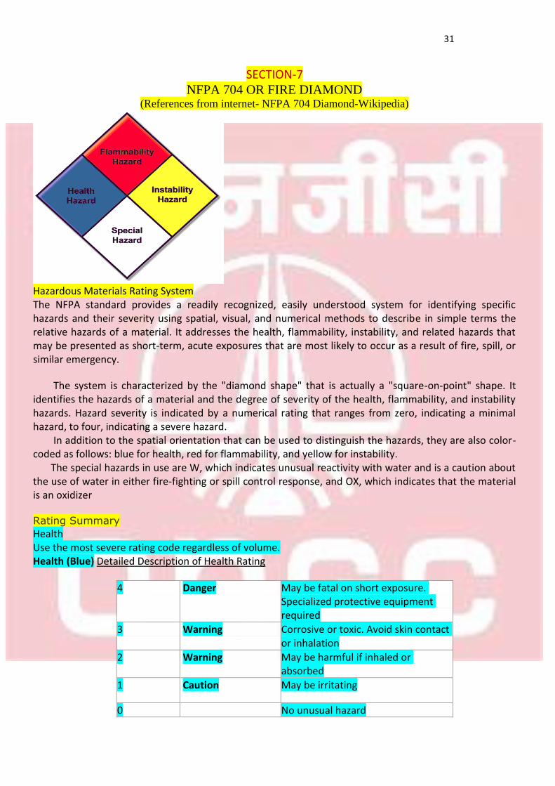
Hazardous Materials Rating System
The NFPA standard provides a readily recognized, easily understood system for identifying specific hazards and their severity using spatial, visual, and numerical methods to describe in simple terms the relative hazards of a material. It addresses the health, flammability, instability, and related hazards that may be presented as short-term, acute exposures that are most likely to occur as a result of fire, spill, or similar emergency.
The system is characterized by the "diamond shape" that is actually a "square-on-point" shape. It identifies the hazards of a material and the degree of severity of the health, flammability, and instability hazards. Hazard severity is indicated by a numerical rating that ranges from zero, indicating a minimal hazard, to four, indicating a severe hazard. In addition to the spatial orientation that can be used to distinguish the hazards, they are also color-coded as follows: blue for health, red for flammability, and yellow for instability. The special hazards in use are W, which indicates unusual reactivity with water and is a caution about the use of water in either fire-fighting or spill control response, and OX, which indicates that the material is an oxidizer
Rating Summary
Health
Use the most severe rating code regardless of volume. Health (Blue) Detailed Description of Health Rating
May be fatal on short exposure. Specialized protective equipment required
Danger 4
Corrosive or toxic. Avoid skin contact or inhalation
Warning 3
May be harmful if inhaled or absorbed
Warning 2
May be irritating Caution 1
No unusual hazard 0
32
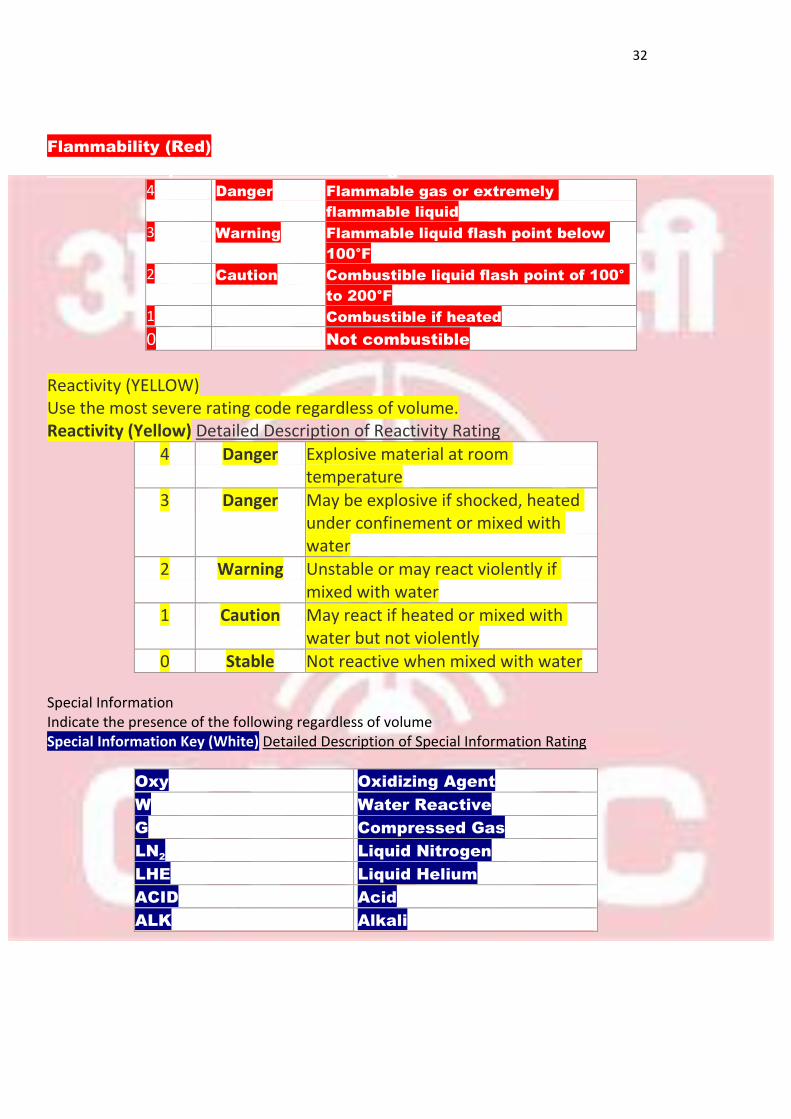
Flammability (Red)D
etailed Description of Flammable Rating
Flammable gas or extremely
flammable liquid
Danger 4
Flammable liquid flash point below
100°F
Warning 3
Combustible liquid flash point of 100°
to 200°F
Caution 2
Combustible if heated 1
Not combustible 0
Reactivity (YELLOW)
Use the most severe rating code regardless of volume. Reactivity (Yellow) Detailed Description of Reactivity Rating
Explosive material at room temperature
Danger 4
May be explosive if shocked, heated under confinement or mixed with water
Danger 3
Unstable or may react violently if mixed with water
Warning 2
May react if heated or mixed with water but not violently
Caution 1
Not reactive when mixed with water Stable 0
Special Information
Indicate the presence of the following regardless of volume
Special Information Key (White) Detailed Description of Special Information Rating
Oxidizing Agent Oxy
Water Reactive W
Compressed Gas G
Liquid Nitrogen LN2
Liquid Helium LHE
Acid ACID
Alkali ALK
33
SECTION-8
HAZARDOUS AREAS
AND
GROUPING OF MOTORS
34
SECTION-8
HAZARDOUS AREAS AND
GROUPING OF MOTORS/EQUIPMENTS (References from CEA REGN-2010, CIMFL, Dhanbad lectures by A.K Singh and R.K Vishwakarma)
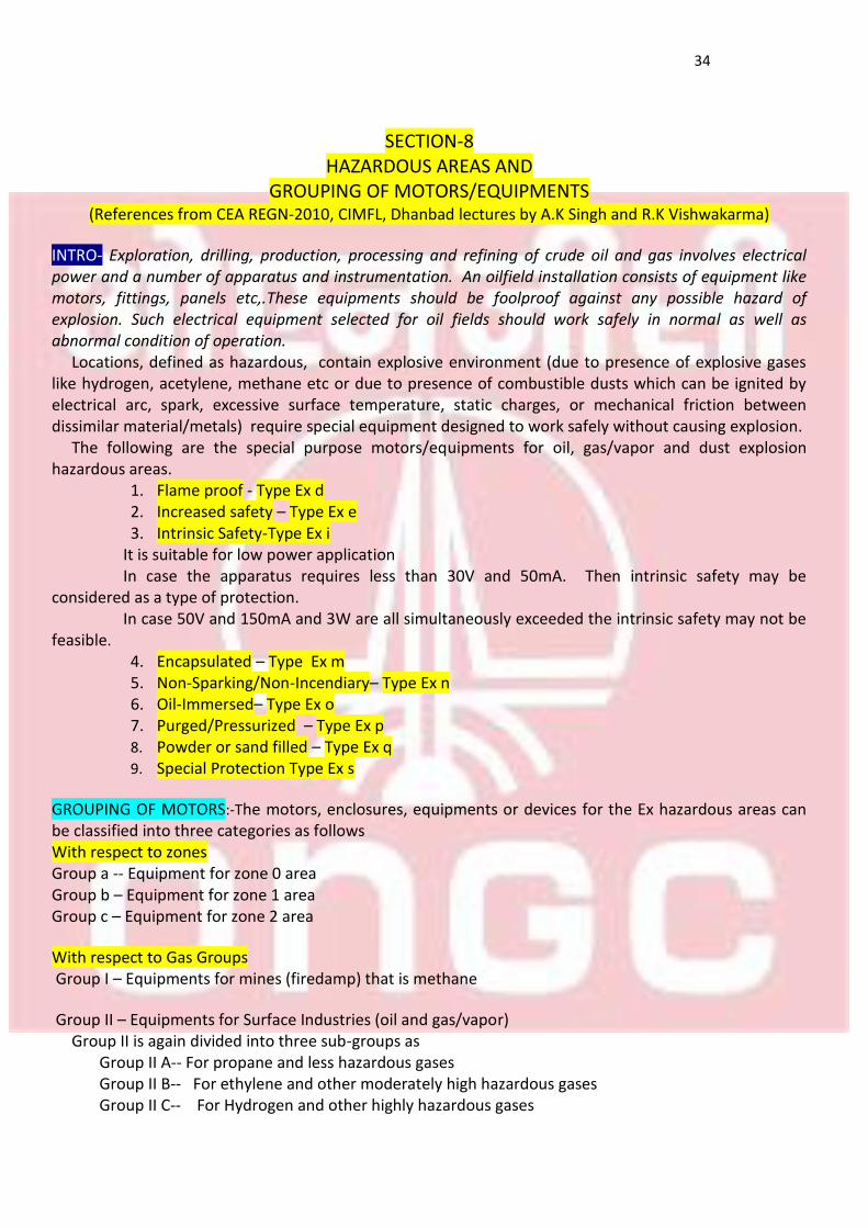
INTRO- Exploration, drilling, production, processing and refining of crude oil and gas involves electrical power and a number of apparatus and instrumentation. An oilfield installation consists of equipment like motors, fittings, panels etc,.These equipments should be foolproof against any possible hazard of explosion. Such electrical equipment selected for oil fields should work safely in normal as well as abnormal condition of operation. Locations, defined as hazardous, contain explosive environment (due to presence of explosive gases like hydrogen, acetylene, methane etc or due to presence of combustible dusts which can be ignited by electrical arc, spark, excessive surface temperature, static charges, or mechanical friction between dissimilar material/metals) require special equipment designed to work safely without causing explosion. The following are the special purpose motors/equipments for oil, gas/vapor and dust explosion hazardous areas.
1. Flame proof - Type Ex d 2. Increased safety – Type Ex e 3. Intrinsic Safety-Type Ex i
It is suitable for low power application
In case the apparatus requires less than 30V and 50mA. Then intrinsic safety may be considered as a type of protection. In case 50V and 150mA and 3W are all simultaneously exceeded the intrinsic safety may not be feasible.
4. Encapsulated – Type Ex m 5. Non-Sparking/Non-Incendiary– Type Ex n 6. Oil-Immersed– Type Ex o 7. Purged/Pressurized – Type Ex p 8. Powder or sand filled – Type Ex q
9. Special Protection Type Ex s
GROUPING OF MOTORS:-The motors, enclosures, equipments or devices for the Ex hazardous areas can be classified into three categories as follows
With respect to zones
Group a -- Equipment for zone 0 area
Group b – Equipment for zone 1 area
Group c – Equipment for zone 2 area
With respect to Gas Groups
Group I – Equipments for mines (firedamp) that is methane
Group II – Equipments for Surface Industries (oil and gas/vapor) Group II is again divided into three sub-groups as
Group II A-- For propane and less hazardous gases
Group II B-- For ethylene and other moderately high hazardous gases
Group II C-- For Hydrogen and other highly hazardous gases
35
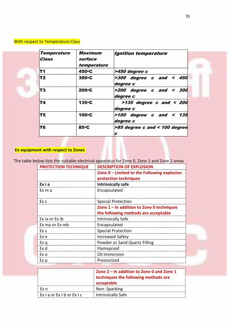
With respect to Temperature Class
Ignition temperature Maximum
surface
temperature
Temperature
Class
>450 degree c 450oC T1
>300 degree c and < 450
degree c
300oC T2
>200 degree c and < 300
degree c
200oC T3
>135 degree c and < 200
degree c
135oC T4
>100 degree c and < 135
degree c
100oC T5
>85 degree c and < 100 degree
c
85oC T6
Ex equipment with respect to Zones
The table below lists the suitable electrical apparatus for Zone 0, Zone 1 and Zone 2 areas
DESCRIPTION OF EXPLOSION PROTECTION TECHNIQUE
Zone 0 – Limited to the Following explosion protection techniques
Intrinsically safe Ex i a
Encapsulated
Ex m a
Special Protection Ex s
Zone 1 – In addition to Zone 0 techniques the following methods are acceptable
Intrinsically Safe Ex ia or Ex ib
Encapsulated Ex ma or Ex mb
Special Protection Ex s
Increased Safety Ex e
Powder or Sand Quartz Filling Ex q
Flameproof Ex d
Oil Immersion Ex o
Pressurized Ex p
Zone 2 – In addition to Zone 0 and Zone 1 techniques the following methods are acceptable
Non- Sparking Ex n
Intrinsically Safe Ex I a or Ex I b or Ex I c
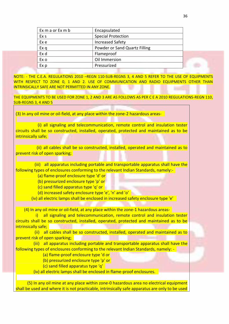
36
Encapsulated Ex m a or Ex m b
Special Protection Ex s
Increased Safety Ex e
Powder or Sand Quartz Filling Ex q
Flameproof Ex d
Oil Immersion Ex o
Pressurized Ex p
NOTE: - THE C.E.A. REGULATIONS 2010 –REGN 110-SUB-REGNS 3, 4 AND 5 REFER TO THE USE OF EQUIPMENTS WITH RESPECT TO ZONE 0, 1 AND 2. USE OF COMMUNICATION AND RADIO EQUIPMENTS OTHER THAN INTRINSICALLY SAFE ARE NOT PERMITTED IN ANY ZONE. THE EQUIPMENTS TO BE USED FOR ZONE 1, 2 AND 3 ARE AS FOLLOWS AS PER C E A 2010 REGULATIONS-REGN 110, SUB-REGNS 3, 4 AND 5
(3) In any oil mine or oil-field, at any place within the zone-2 hazardous areas- (i) all signaling and telecommunication, remote control and insulation tester circuits shall be so constructed, installed, operated, protected and maintained as to be intrinsically safe; (ii) all cables shall be so constructed, installed, operated and maintained as to prevent risk of open sparking; (iii) all apparatus including portable and transportable apparatus shall have the following types of enclosures conforming to the relevant Indian Standards, namely:- (a) flame-proof enclosure type 'd' or (b) pressurized enclosure type 'p' or (c) sand filled apparatus type 'q' or (d) increased safety enclosure type 'e', 'n' and 'o' (iv) all electric lamps shall be enclosed in increased safety enclosure type 'e’ (4) In any oil mine or oil-field, at any place within the zone-1 hazardous areas- i) all signaling and telecommunication, remote control and insulation tester circuits shall be so constructed, installed, operated, protected and maintained as to be intrinsically safe; (ii) all cables shall be so constructed, installed, operated and maintained as to prevent risk of open sparking; (iii) all apparatus including portable and transportable apparatus shall have the following types of enclosures conforming to the relevant Indian Standards, namely: - (a) flame-proof enclosure type 'd or (b) pressurized enclosure type 'p' or (c) sand filled apparatus type ‘q' (iv) all electric lamps shall be enclosed in flame-proof enclosures. (5) In any oil mine at any place within zone-0 hazardous area no electrical equipment shall be used and where it is not practicable, intrinsically safe apparatus are only to be used
37
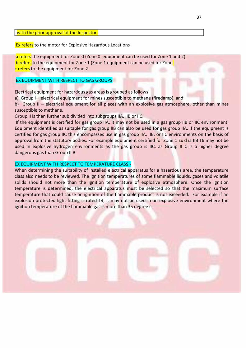
with the prior approval of the Inspector.
Ex refers to the motor for Explosive Hazardous Locations
a refers the equipment for Zone 0 (Zone 0 equipment can be used for Zone 1 and 2)
b refers to the equipment for Zone 1 (Zone 1 equipment can be used for Zone c refers to the equipment for Zone 2
EX EQUIPMENT WITH RESPECT TO GAS GROUPS
Electrical equipment for hazardous gas areas is grouped as follows: a) Group I – electrical equipment for mines susceptible to methane (firedamp), and b) Group II – electrical equipment for all places with an explosive gas atmosphere, other than mines susceptible to methane. Group II is then further sub divided into subgroups IIA, IIB or IIC. If the equipment is certified for gas group IIA, it may not be used in a gas group IIB or IIC environment. Equipment identified as suitable for gas group IIB can also be used for gas group IIA. If the equipment is certified for gas group IIC this encompasses use in gas group IIA, IIB, or IIC environments on the basis of approval from the statutory bodies. For example equipment certified for Zone 1 Ex d ia IIB T6 may not be used in explosive hydrogen environments as the gas group is IIC, as Group II C is a higher degree dangerous gas than Group II B
EX EQUIPMENT WITH RESPECT TO TEMPERATURE CLASS:- When determining the suitability of installed electrical apparatus for a hazardous area, the temperature class also needs to be reviewed. The ignition temperatures of some flammable liquids, gases and volatile solids should not more than the ignition temperature of explosive atmosphere. Once the ignition temperature is determined, the electrical apparatus must be selected so that the maximum surface temperature that could cause an ignition of the flammable product is not exceeded. For example if an explosion protected light fitting is rated T4, it may not be used in an explosive environment where the ignition temperature of the flammable gas is more than 35 degree c.
38
SECTION-9 CONCEPTS OF
EX HAZARDOUS EQUIPMENTS
39
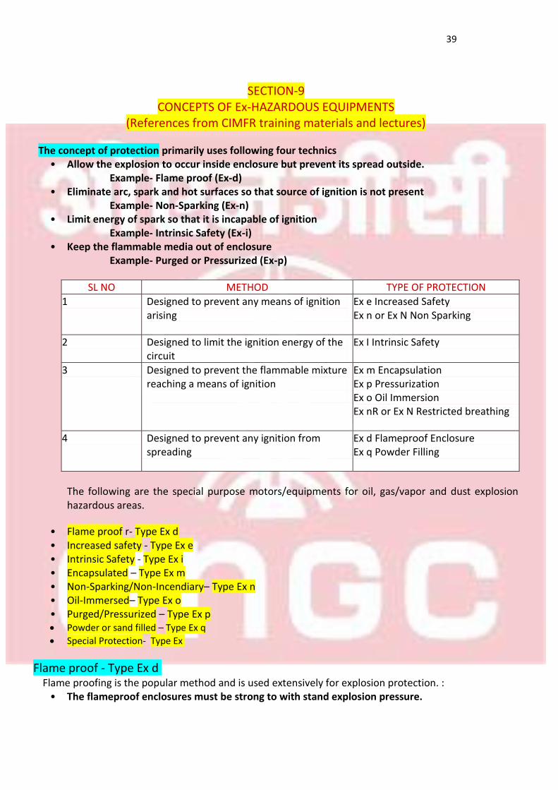
SECTION-9
CONCEPTS OF Ex-HAZARDOUS EQUIPMENTS (References from CIMFR training materials and lectures)
The concept of protection primarily uses following four technics
• Allow the explosion to occur inside enclosure but prevent its spread outside. Example- Flame proof (Ex-d)
• Eliminate arc, spark and hot surfaces so that source of ignition is not present Example- Non-Sparking (Ex-n)
• Limit energy of spark so that it is incapable of ignition Example- Intrinsic Safety (Ex-i)
• Keep the flammable media out of enclosure Example- Purged or Pressurized (Ex-p)
TYPE OF PROTECTION METHOD SL NO
Ex e Increased Safety
Ex n or Ex N Non Sparking
Designed to prevent any means of ignition arising
1
Ex I Intrinsic Safety Designed to limit the ignition energy of the circuit
2
Ex m Encapsulation
Ex p Pressurization
Ex o Oil Immersion
Ex nR or Ex N Restricted breathing
Designed to prevent the flammable mixture reaching a means of ignition
3
Ex d Flameproof Enclosure
Ex q Powder Filling
Designed to prevent any ignition from spreading
4
The following are the special purpose motors/equipments for oil, gas/vapor and dust explosion hazardous areas.
• Flame proof r- Type Ex d • Increased safety - Type Ex e • Intrinsic Safety - Type Ex i • Encapsulated – Type Ex m • Non-Sparking/Non-Incendiary– Type Ex n • Oil-Immersed– Type Ex o • Purged/Pressurized – Type Ex p Powder or sand filled – Type Ex q
Special Protection- Type Ex
Flame proof - Type Ex d Flame proofing is the popular method and is used extensively for explosion protection. :
• The flameproof enclosures must be strong to with stand explosion pressure.
40
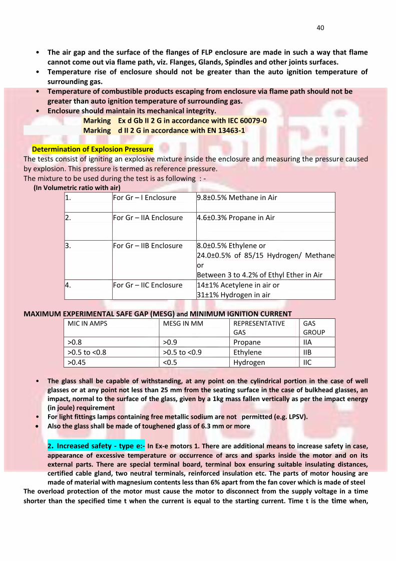
• The air gap and the surface of the flanges of FLP enclosure are made in such a way that flame cannot come out via flame path, viz. Flanges, Glands, Spindles and other joints surfaces.
• Temperature rise of enclosure should not be greater than the auto ignition temperature of surrounding gas.
• Temperature of combustible products escaping from enclosure via flame path should not be greater than auto ignition temperature of surrounding gas.
• Enclosure should maintain its mechanical integrity. Marking Ex d Gb II 2 G in accordance with IEC 60079-0
Marking d II 2 G in accordance with EN 13463-1
Determination of Explosion Pressure
The tests consist of igniting an explosive mixture inside the enclosure and measuring the pressure caused by explosion. This pressure is termed as reference pressure. The mixture to be used during the test is as following : - (In Volumetric ratio with air)
9.8±0.5% Methane in Air For Gr – I Enclosure 1.
4.6±0.3% Propane in Air
For Gr – IIA Enclosure 2.
8.0±0.5% Ethylene or
24.0±0.5% of 85/15 Hydrogen/ Methane or Between 3 to 4.2% of Ethyl Ether in Air
For Gr – IIB Enclosure 3.
14±1% Acetylene in air or
31±1% Hydrogen in air
For Gr – IIC Enclosure 4.
MAXIMUM EXPERIMENTAL SAFE GAP (MESG) and MINIMUM IGNITION CURRENT
GAS GROUP
REPRESENTATIVE GAS
MESG IN MM MIC IN AMPS
IIA Propane >0.9 >0.8
IIB Ethylene >0.5 to <0.9 >0.5 to <0.8
IIC Hydrogen <0.5 >0.45
• The glass shall be capable of withstanding, at any point on the cylindrical portion in the case of well
glasses or at any point not less than 25 mm from the seating surface in the case of bulkhead glasses, an impact, normal to the surface of the glass, given by a 1kg mass fallen vertically as per the impact energy (in joule) requirement
• For light fittings lamps containing free metallic sodium are not permitted (e.g. LPSV).
Also the glass shall be made of toughened glass of 6.3 mm or more
2. Increased safety - type e:- In Ex-e motors 1. There are additional means to increase safety in case,
appearance of excessive temperature or occurrence of arcs and sparks inside the motor and on its external parts. There are special terminal board, terminal box ensuring suitable insulating distances, certified cable gland, two neutral terminals, reinforced insulation etc. The parts of motor housing are made of material with magnesium contents less than 6% apart from the fan cover which is made of steel
The overload protection of the motor must cause the motor to disconnect from the supply voltage in a time
shorter than the specified time t when the current is equal to the starting current. Time t is the time when,
41
during the flow of the starting current, the motor winding heats up to the limit temperature from the temperature of rated conditions at maximum ambient temperature The motors can be provided with a cable gland with a holder (protecting the supply wire against pulling out).The motors that are provided with special fan cover can work in perpendicular position with the shaft down 1. High integrity- minimum IP 54 2. Protected against self-loosening of wires 3. Minimum Impact resistance-7 Joules
The motors are suitable for zone 2 Marking Ex e Gb II 2 G in accordance with IEC 60079-0
3. Intrinsic Safety Devices- Type Ex i- The primary concept behind intrinsic safety is the restriction of available electrical and thermal energy in the system so that ignition of a hazardous atmosphere (explosive gas or dust) cannot occur. This is achieved by ensuring that only low voltages and currents enter the hazardous area, and that no significant energy storage is possible. It is suitable for low power applications like gas detectors, meters and instruments In case the apparatus requires less than 30V and 50mA. Then intrinsic safety may be considered as a type of protection. In case 50V and 150mA and 3W are all simultaneously exceeded the intrinsic safety may not be feasible. It is suitable for zone 0 (as well as 1 and 2) Marking Ex ia/ib/ic Ga/Gb/Gc II 1/2/3 G in accordance with IEC 60079-0
Marking Ex ia/ib/ic Da/Db/Dc II 1/2/3 D in accordance with IEC 61241-0
4. Encapsulated – type Ex mThe electronic circuit is encapsulated (in, for example and epoxy resin)
which prevents and internal ignition-capable parts igniting the surrounding explosive atmosphere. The T-Class will refer to the maximum temperature the external surface will exhibit. Mostly used for small and low cost items because repair is not possible. Ex m: suitable for zones 1 and 2 (not zone 0). Equipment Category 2G
Ex m a: suitable for zones 0 and 1 and 2. Equipment Category 1G
Ex m b: suitable for zones 1 and 2 (not zone 0). Equipment Category 2G
Ex m c: suitable for zone 2 (not zones 1 and 0). Equipment Category 3G
Marking Ex ma/mb/mc Ga/Gb/Gc II 1/2/3 G in accordance with IEC 60079-0
Marking Ex ma/mb/mc Da/Db/Dc II 1/2/3 D in accordance with IEC 61241-0 Applications 1. Small fuses 2. Electronic Devices 3. Sensors
Non Sparking/Non Incendiary motor/enclosure – Type Exn 1. Non‐Sparking is a lesser degree of protection than Exe standard industrial equipment that under normal operation will not produce arcs sparks or surface temperature high enough to cause ignition of the surrounding gas vapor mixture
42
Typical products include Zone 2 lighting fixtures and certain enclosures... Electric motors (Squirrel cage motors), terminal boxes, fuses, LEDs, transformers, apparatus requiring low energy plug connectors cells batteries plug connectors, cells, batteries, etc,.and the design concept includes,
Non-sparking vibration proof terminals
Adequate creepage distance and clearance between terminals
Motor bars in the slots with brazed ends to prevent sparks Marking Ex nC Gc II 3 G in accordance with IEC 60079-0
Marking Ex nA Gc II 3 G in accordance with IEC 60079-0
Minimum degree of protection IP 20 for motor enclosure and IP 54 for terminal box Clearance is the distance between two un-insulated conductors through air Creepage distance is the shortest distance between two un insulated conductors along an insulated surface 6. Oil-Immersed– Type Ex o 1. This is a technique primarily used for switch gear
2. Spark is formed under the oil and venting of spark is controlled
3. Suitable for zone 1 and 2 area 1) Marking Ex o Gb II 2 G in accordance with IEC 60079-0
2) Marking Ex k II 2 G in accordance with EN 13463-1 Applications 1. Contactors 2. Switches
NOTE - o-refers to oil immersion and k-refers to liquid immersion
7. Purged/Pressurized – Type Ex p
Applications of Ex ‘p’ protections are
High volume panels or motors
Complicated panels having number of connected enclosures
High voltage electrical apparatus, etc. METHODS OF PRESSURIZATION The pressurization may be achieved using one of the two methods:
1. PRESSURIZATION BY CONTINUOUS CIRCULATION OF PROTECTIVE GAS: A method of
maintaining the overpressure within a pressurized enclosure in which, after purging, the
protective gas is passed continuously through the enclosure.
2. PRESSURIZATION WITH LEAKAGE COMPENSATION: A method of maintaining the
overpressure within a pressurized enclosure in which, when the exit apertures are closed; the
supply of protective gas is sufficient to compensate the inevitable leakages from the
pressurized enclosure and its ducts.
OVERPRESSURE AND RATE OF FLOW OF PROTECTIVE GAS
43
As per standard IS: 7389 (part-1)-1976 the minimum overpressure maintained should be 5mm of
WC or 0.5mbar. The rate of flow should be controlled such as the min. overpressure should remain
maintained.
OVERPRESSURE AND RATE OF FLOW OF PROTECTIVE GAS
As per standard IS: 7389 (part-1)-1976 the minimum overpressure maintained should be 5mm of
WC or 0.5mbar. The rate of flow should be controlled such as the min. overpressure should remain
maintained INGRESS PROTECTION
The minimum IP protection required for the Ex ‘p’ enclosure is IP40.
Cable entries and sealing
All cable entries and conduit connections should be sealed to maintain the IP rating as well as to
minimize the leakages of the protective gas.
TEMPERATURE LIMITS
The maximum surface temperature of the apparatus should be less than the permissible
temperature range. The temperature classification is determined by the higher of the following
temperatures: maximum surface temperature of the apparatus; or the maximum surface
temperature of any internal parts which are protected by another type of protection and which
remain energized even when the pressurization is removed.
Also the temperature of the protective gas should not normally exceed the ambient temperature
at the inlet of the apparatus. This protection is suitable foe zone 1 as well as zone 2
SAFETY PROVISIONS AND DEVICES
All safety devices, which are used to ensure the pressurized equipment cannot cause an explosion, shall themselves be protected that they do not constitute an explosion hazard. Some safety devices listed below are needed in the safe operation of the Ex ‘p’ panels:
• Time delay switch • Pressure gauges pneumatic type • Power cut off switch • Audible/Visual Indicators • Solenoid valves
The complete control instrumentation covering all such safety devices is built up to ensure the proper and safe functioning of these safety devices at the moment. In all cases the safety devices mounted outside the pressurized panels should be protected by any type of Ex protections suitable for the selected
NOTE:-The coding ExnR denotes that the protection method employs a restricted breathing enclosure. The restricted enclosure may be confined to the part of the apparatus containing the hot components such as lamps. Where the normal non-sparking construction is used the coding is nA
Marking Ex p Gb II 2 G in accordance with IEC 60079-0
Marking Ex pD Db II 2 D in accordance with IEC 61241-0
Marking p II 2 G/D in accordance with EN 13463-1
44
Marking Ex pz Gc II 3 G in accordance with IEC 60079-0
Marking Ex nR Gc II 3 G in accordance with IEC 60079-0 The % use of various P type protective enclosures worldwide are Type Y- 5% Type X-20% Type Z- 75%
8. Powder or sand filled – Type Ex q This involves the mounting of potentially incendive components
in an enclosure filled with sand or similar inert powder. It was originally developed to protect heavy duty traction batteries. It is now primarily of use where the incendiary action is the abnormal release of electrical energy by the rupture of fuses or failure of components such as capacitors used in electronic apparatus. The likelihood of possibly incendive failure of the components is assessed
Suitable for zone 1 and zone 2 areas
Marking Ex q Gb II 2 G in accordance with IEC 60079-0 Applications 1. Transformers 2. Capacitors
9 Special Protection Type ex s This protection being by definition special, has no specific rules. In
effect it is any method which can be shown to have the required degree of safety in use. Much apparatus having Ex s protection was designed with encapsulation and this has been incorporated into EN 50028. In addition, the Ex s coding is used when apparatus has been assessed to one of the individual parts of the CENELEC series but does not exactly comply with it. Ex s protection has been commonly used for Zone 0 and Zone 1 application
Marking Ex s II 1/2/3 G in accordance with IEC 60079-
45
SECTION-10 INGRESS PROTECTION
46
SECTION-10
INGRESS PROTECTION (References from CIMFR and internet sources)
IP - Ingress Protection rating is used to specify the environmental protection - electrical enclosure - of electrical equipment
Ingress Protection (IP) ratings are developed by the European Committee for Electro Technical Standardization (CENELEC) (NEMA IEC 60529 Degrees of Protection Provided by Enclosures - IP Code), specifying the environmental protection the enclosure provides. The IP rating normally has two (or three) numbers: 1. Protection from solid objects or materials
2. Protection from liquids (water) Note- Protection against mechanical impacts (commonly omitted, the third number is not a part of IEC 60529) Example - IP Rating
With the IP rating IP 54, 5 describes the level of protection from solid objects and 4 describes the level of protection from liquids. An "X" can be used for one of the digits if there is only one class of protection, i.e. IPX1 which addresses protection against vertically falling drops of water e.g. condensation
NOTE: - Ingress Protection method is an IEC method and it does not specify about corrosion protection whereas NEMA TYPES OF ENCLOSURES, that is, American method specifies corrosion protection and extreme snowfall and icing protection
IP First number - Protection against solid objects 0
No protection
1 Protected against solid objects over 50 mm, e.g. accidental touch by persons hands. 2 Protected against solid objects over 12 mm, e.g. persons fingers. 3 Protected against solid objects over 2.5 mm (tools and wires). 4 Protected against solid objects over 1 mm (tools, wires, and small wires). 5 Protected against dust limited ingress (no harmful deposit). 6 Totally protected against dust.
IP Second number - Protection against liquids 0 No protection. 1 Protection against vertically falling drops of water e.g. condensation. 2 Protection against direct sprays of water up to 15o from the vertical. 3 Protected against direct sprays of water up to 60o from the vertical. 4 Protection against water sprayed from all directions - limited ingress permitted. 5 Protected against low pressure jets of water from all directions - limited ingress.
6 Protected against temporary flooding of water, e.g. for use on ship decks - limited ingress permitted.
7 Protected against the effect of immersion between 15 cm and 1 m.
8 Protects against long periods of immersion under pressure
47
COMPARISON BETWEEN IEC AND NEMA RATINGS
IP CODE EQUIVALENT NEMA RATING
IP 20 1
IP 54 3
IP 65 4, 4X
IP 67 6
IP 68 6P
INTRODUCTION ENVIRONMENTAL PROTECTION
NEMA and CSA Type Enclosure for non hazardous areas
NEMA – NATIONAL ELECTRICAL MANUFACTURERS ASSOCIATION (AMERICA) CSA- CANADIAN STANDAEDS ASSOCIATION
NEMA or CSA Type 1 Enclosures are intended for indoor use primarily to provide a degree of protection against limited amounts of falling dirt. This type is not specifically identified in the CSA Standard. NEMA or CSA Type 2 Enclosures are intended for indoor use primarily to provide a degree of protection against limited amounts of falling water and dirt. NEMA or CSA Type 3 Enclosures are intended for outdoor use primarily to provide a degree of protection against rain, sleet, windblown dust; and damage from external ice formation. NEMA or CSA Type 3R Enclosures are intended for outdoor use primarily to provide a degree of protection against rain, sleet; and damage from external ice formation, and must have a drain hole. NEMA or CSA Type 3S Enclosures are intended for outdoor use primarily to provide a degree of protection against rain, sleet, windblown dust; and to provide for operation of external mechanisms when ice laden. NEMA or CSA Type 4 Enclosures are intended for indoor or outdoor use primarily to provide a degree of protection against windblown dust and rain, splashing water, hose directed water; and damage from external ice formation. NEMA or CSA Type 4X Enclosures are intended for indoor or outdoor use primarily to provide a degree of protection against corrosion, windblown dust and rain, splashing water, hose directed water; and damage from external ice formation. NEMA or CSA Type 5 Enclosures are intended for indoor use primary to provide a degree of protection against settling airborne dust, falling dirt, and dripping non-corrosive liquids. NEMA or CSA Type 6 Enclosures are intended for indoor or outdoor use primarily to provide a degree of protection against hose-directed water, the entry of water during occasional temporary submersion at a limited depth; and damage from external ice formation. NEMA or CSA Type 6P Enclosures are intended for indoor or outdoor use primarily to provide a degree of protection against hose-directed water, the entry of water during prolonged submersion at a limited depth; and damage from external ice formation. NEMA or CSA Type 12 Enclosures are intended for indoor use primarily to provide a degree of protection against circulating dust, falling dirt, and dripping non-corrosive liquids. NEMA or CSA Type 12K Enclosures with knockouts are intended for indoor use primarily to provide a degree of protection against circulating dust, falling dirt, and dripping non-corrosive liquids. NEMA or CSA Type 13 Enclosures are intended for indoor use primarily to provide a degree of protection against dust, spraying of water, oil, and non-corrosive coolant.
48
Definitions Referring To NEMA Requirements for Hazardous Location The following NEMA type enclosures occasionally appear on specifications and product literature NEMA 7 Enclosures are intended for indoor use in locations classified as Class I, Groups A, B, C, or D, as defined in the NEC. NEMA 8 Enclosures are for in-door or outdoor use in locations classified as Class I, Groups A, B, C, or D, as defined in the NEC. NEMA 9 Enclosures are intended for indoor use in locations classified as Class II, Groups E, F, and G, as defined in the NEC. NEMA 10 Enclosures are constructed to meet the applicable requirements of the Mine Safety and Health Administration (MSHA) PRINCIPLES OF LIQUID FILTRATION
Liquid Filtration Liquid filtration involves the removal of contaminant particles in a fluid system. The grade of filter chosen for a specific application is usually determined by the size of the particle to be removed. Contaminant particles are measured using the "micron" unit of measurement.
Micron A micron is a metric unit of measurement where one micron is equivalent to one- one thousandth of a milli meter *1 micron (1μ) = 1/1000 mm+ or 1 micron (micrometer) = 1/1,000,000 of a meter. A human red blood cell is 5 microns An average human hair has a diameter of 100 microns Most humans cannot see anything smaller than 40 microns with the unaided eye.
49
SECTION-11 UNDERSTANDING
EX-PROTECTION NAME PLATE DEAILS
50
SECTION 11
UNDERSTANDING Ex PROTECTION NAMEPLATE DETAILS (References from miscellaneous internet sources)
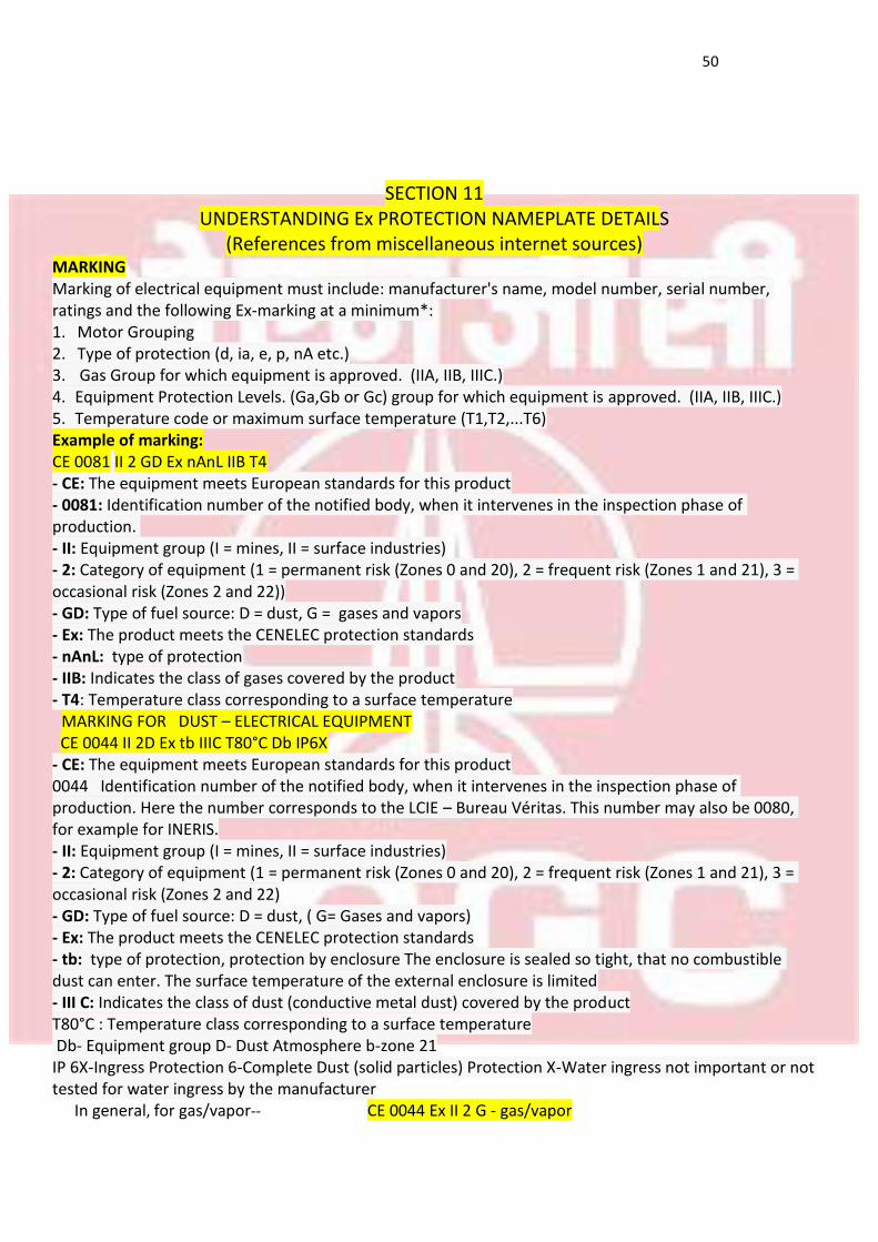
MARKING
Marking of electrical equipment must include: manufacturer's name, model number, serial number, ratings and the following Ex-marking at a minimum*: 1. Motor Grouping
2. Type of protection (d, ia, e, p, nA etc.)
3. Gas Group for which equipment is approved. (IIA, IIB, IIIC.)
4. Equipment Protection Levels. (Ga,Gb or Gc) group for which equipment is approved. (IIA, IIB, IIIC.)
5. Temperature code or maximum surface temperature (T1,T2,...T6)
Example of marking: CE 0081 II 2 GD Ex nAnL IIB T4 - CE: The equipment meets European standards for this product
- 0081: Identification number of the notified body, when it intervenes in the inspection phase of production. - II: Equipment group (I = mines, II = surface industries)
- 2: Category of equipment (1 = permanent risk (Zones 0 and 20), 2 = frequent risk (Zones 1 and 21), 3 = occasional risk (Zones 2 and 22)) - GD: Type of fuel source: D = dust, G = gases and vapors
- Ex: The product meets the CENELEC protection standards
- nAnL: type of protection - IIB: Indicates the class of gases covered by the product - T4: Temperature class corresponding to a surface temperature MARKING FOR DUST – ELECTRICAL EQUIPMENT
CE 0044 II 2D Ex tb IIIC T80°C Db IP6X
- CE: The equipment meets European standards for this product 0044 Identification number of the notified body, when it intervenes in the inspection phase of production. Here the number corresponds to the LCIE – Bureau Véritas. This number may also be 0080, for example for INERIS. - II: Equipment group (I = mines, II = surface industries) - 2: Category of equipment (1 = permanent risk (Zones 0 and 20), 2 = frequent risk (Zones 1 and 21), 3 = occasional risk (Zones 2 and 22) - GD: Type of fuel source: D = dust, ( G= Gases and vapors) - Ex: The product meets the CENELEC protection standards - tb: type of protection, protection by enclosure The enclosure is sealed so tight, that no combustible dust can enter. The surface temperature of the external enclosure is limited - III C: Indicates the class of dust (conductive metal dust) covered by the product T80°C : Temperature class corresponding to a surface temperature Db- Equipment group D- Dust Atmosphere b-zone 21 IP 6X-Ingress Protection 6-Complete Dust (solid particles) Protection X-Water ingress not important or not tested for water ingress by the manufacturer In general, for gas/vapor-- CE 0044 Ex II 2 G - gas/vapor
51
For dust -- CE 0044 Ex II 2 D - dust
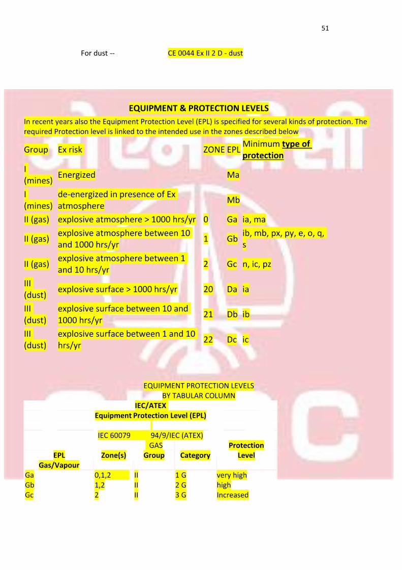
EQUIPMENT & PROTECTION LEVELS
In recent years also the Equipment Protection Level (EPL) is specified for several kinds of protection. The required Protection level is linked to the intended use in the zones described below
Group Ex risk ZONE EPL Minimum type of protection
I (mines)
Energized Ma
I (mines)
de-energized in presence of Ex atmosphere
Mb
II (gas) explosive atmosphere > 1000 hrs/yr 0 Ga ia, ma
II (gas) explosive atmosphere between 10 and 1000 hrs/yr
1 Gb ib, mb, px, py, e, o, q, s
II (gas) explosive atmosphere between 1 and 10 hrs/yr
2 Gc n, ic, pz
III (dust)
explosive surface > 1000 hrs/yr 20 Da ia
III (dust)
explosive surface between 10 and 1000 hrs/yr
21 Db ib
III (dust)
explosive surface between 1 and 10 hrs/yr
22 Dc ic
EQUIPMENT PROTECTION LEVELS
BY TABULAR COLUMN IEC/ATEX
Equipment Protection Level (EPL)
IEC 60079 94/9/IEC (ATEX)
EPL
Zone(s) GAS
Group
Category Protection
Level Gas/Vapour
Ga 0,1,2 II 1 G very high Gb 1,2 II 2 G high Gc 2 II 3 G Increased
52
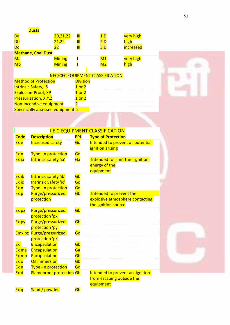
I E C EQUIPMENT CLASSIFICATION Code Description EPL Type of Protection
Ex e Increased safety Gc Intended to prevent a potential ignition arising
Ex n Type - n protection Gc
Ex ia Intrinsic safety 'ia' Ga Intended to limit the ignition energy of the equipment
Ex ib Intrinsic safety 'ib' Gb
Ex ic Intrinsic Safety 'ic' Gc
Ex n Type - n protection Gc
Ex p Purge/pressurized protection
Gb Intended to prevent the explosive atmosphere contacting the ignition source
Ex px Purge/pressurized protection 'px'
Gb
Ex py Purge/pressurized protection 'py'
Gb
Emx pz Purge/pressurized protection 'pz'
Gc
Ex Encapsulation Gb Ex ma Encapsulation Ga Ex mb Encapsulation Gb Ex o Oil immersion Gb Ex n Type - n protection Gc Ex d Flameproof protection Gb Intended to prevent an ignition
from escaping outside the equipment
Ex q Sand / powder Gb
Dusts Da 20,21,22 III 1 D very high Db 21,22 III 2 D high Dc 22 III 3 D increased Methane, Coal Dust Ma Mining I M1 very high Mb Mining I M2 high
NEC/CEC EQUIPMENT CLASSIFICATION
Method of Protection Division Intrinsic Safety, IS 1 or 2 Explosion-Proof, XP 1 or 2 Pressurization, X,Y,Z 1 or 2 Non-incendive equipment 2 Specifically assessed equipment 2
53
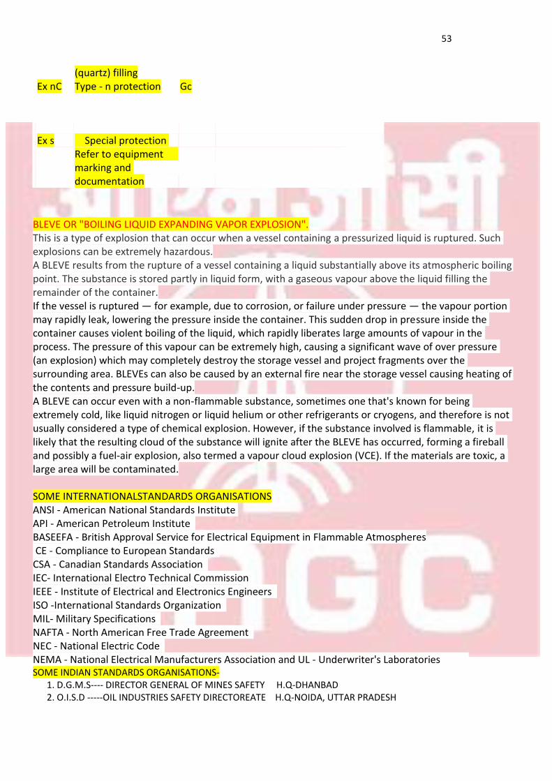
(quartz) filling Ex nC Type - n protection Gc
Ex s Special protection Refer to equipment marking and documentation
BLEVE OR "BOILING LIQUID EXPANDING VAPOR EXPLOSION". This is a type of explosion that can occur when a vessel containing a pressurized liquid is ruptured. Such explosions can be extremely hazardous. A BLEVE results from the rupture of a vessel containing a liquid substantially above its atmospheric boiling point. The substance is stored partly in liquid form, with a gaseous vapour above the liquid filling the remainder of the container. If the vessel is ruptured — for example, due to corrosion, or failure under pressure — the vapour portion may rapidly leak, lowering the pressure inside the container. This sudden drop in pressure inside the container causes violent boiling of the liquid, which rapidly liberates large amounts of vapour in the process. The pressure of this vapour can be extremely high, causing a significant wave of over pressure (an explosion) which may completely destroy the storage vessel and project fragments over the surrounding area. BLEVEs can also be caused by an external fire near the storage vessel causing heating of the contents and pressure build-up. A BLEVE can occur even with a non-flammable substance, sometimes one that's known for being extremely cold, like liquid nitrogen or liquid helium or other refrigerants or cryogens, and therefore is not usually considered a type of chemical explosion. However, if the substance involved is flammable, it is likely that the resulting cloud of the substance will ignite after the BLEVE has occurred, forming a fireball and possibly a fuel-air explosion, also termed a vapour cloud explosion (VCE). If the materials are toxic, a large area will be contaminated. SOME INTERNATIONALSTANDARDS ORGANISATIONS ANSI - American National Standards Institute API - American Petroleum Institute BASEEFA - British Approval Service for Electrical Equipment in Flammable Atmospheres CE - Compliance to European Standards CSA - Canadian Standards Association IEC- International Electro Technical Commission IEEE - Institute of Electrical and Electronics Engineers ISO -International Standards Organization MIL- Military Specifications NAFTA - North American Free Trade Agreement NEC - National Electric Code NEMA - National Electrical Manufacturers Association and UL - Underwriter's Laboratories SOME INDIAN STANDARDS ORGANISATIONS- 1. D.G.M.S---- DIRECTOR GENERAL OF MINES SAFETY H.Q-DHANBAD 2. O.I.S.D -----OIL INDUSTRIES SAFETY DIRECTOREATE H.Q-NOIDA, UTTAR PRADESH
54
3. I.E.R 1956—INDIAN ELECTRICITY RULES 1956 I NOW CENTRAL ELECTRICITY AUTHORITY REGULATIONS 2010
4. CENTRAL MINES RESEARCH INSTITUTE 5. CENTRAL FUEL RESEARCH INSTITUTE BOTH COMBINED AND NOW CENTRAL INSTITUTE OF MINES AND FUEL RESEARCH H.Q-DHANBAD 6. C.C.E--- CHIEF CONTROLLER OF EXPLOSIVES I NOW P.E.S.O---- PETROLEUM AND EXPLOSIVES SAFETY ORGANISATION H.Q- NAGPUR 7. O.M.R. 1984---- OIL MINES REGULATIONS 1984
55
SECTION-12
DEFINING HAZARDOUS AREA
OR
ZONE EXTENT
56
SECTION-12 DEFINING THE EXTENT OF HAZARDOUS
AREAS AND ZONES EXTENT OF HAZARDOUS AREA- GENERAL CONSIDERATIONS
A complete knowledge of the physical properties of the flammable materials involved is essential for classifying a hazardous area. Properties and parameters of primary interest from an ignition standpoint are:
(a) Relative density (whether lighter or heavier than air) (b) Gas group (whether group II A, II B or II C)
(c) Flammable limits (d) Flash point (e) Volatility (f) Ignition temperature (g) Ignition energy (h) The level of ventilation (whether high, medium or low) (i)The rate of release or discharge Some of these characteristics have a direct influence on the degree and/or extent of hazardous areas while the others affect the design of electrical equipment. Some of the factors affecting the extent of hazardous zones and areas are as follows:
a) Where a gas or vapour is released into the atmosphere having a relative density less than one, the lighter vapour will rise in a comparatively still atmosphere. A vapour density greater than one, that is heavier than-air indicates the gas or vapour will tend to sink, and may thereby spread over some distance horizontally at a lower level. The latter effects will increase with compounds of greater relative vapour density.
b) The lower the “lower flammable limit” the larger may be the extent of the hazardous area.
c) A flammable atmosphere cannot exist if the flash point is significantly above the relevant
maximum temperature of the flammable liquid. The lower the flashpoint, the larger may be the extent of the hazardous area.
d) Ignition temperature and ignition energy of a flammable gas or vapour affect the design of
electrical apparatus for hazardous areas so that these do not present an ignition risk.
e) The extent of hazardous area may increase with increasing rate of release of flammable material.
f) With an increased rate of ventilation, the extent of hazardous area may be reduced. The extent may also be reduced by an improved arrangement of the ventilation system. The lower the degree of ventilation the higher the degree of zone and extent of area.
g) Whether Group II A, II B or II C. Group II A is lightly dangerous, Group II B is moderately dangerous and Group II C is highly dangerous and according to the group or degree of danger the extent may be increased.
57
(REFERENCE: - O I S D STD 113)
NOTE- Depending upon the above factors it is the duty of the production/process engineers and safety officers to decide the extent of hazardous areas and zones and electrical engineers are the first users to follow and implement the provisions with respect to installation of electrical equipments followed by instrumentation, mechanical and other officers.
ANNEXURE
CLASSIFICATION OF HAZARDOUS AREAS IN OIL MINES (UNDER REGULATION 74 OF OIL MINES REGULATION 1984. NO. 1(6)2001-GENL/3604-3753 DATED 12TH SEPT 2001)
A. WELL HEAD AREA
(i) When the derrick is not enclosed and the substructure is open to ventilation, the area in all directions from the base of rotary table extending up to 3m shall be zone-2 hazardous area. Any cellar, trenches and pits below the ground level shall be zone-1 hazardous area, the area lying within 3m in horizontal direction from the edge of any cellar, trenches or pit and 0.5m vertically above the cellar shall be zone-2 hazardous area.
(ii) When the derrick floor and substructure are enclosed, the enclosed substructure below the derrick floor including cellar, pits or sumps below the ground level, shall be zone-1 area, the enclosed area above the derrick floor shall be zone-2 hazardous area.
Mud tank / Channel The free space above the level of mud in tank and channel shall be zone-1 hazardous area; the area in a radius of 3m in all directions from the edge of mud tank and channel shall be zone-2 hazardous area. Shale Shaker
(a) The area within a radius of 1.5m in all directions from the shale shaker in open air shall be zone-1 hazardous area. The area beyond 1.5m and up to 3m in all directions from the shale shaker shall be zone-2 hazardous area.
(b) When the shale shaker is located in an enclosure, the enclosed area shall be zone-1 hazardous area to the extent of the enclosure. The area outside Shale shaker and up to 1.5m in all directions from the shale shaker shall be Zone-2 hazardous area.
Degasser
(a) The area within a radius of 1.5m from the open end of the vent extending in all directions shall be zone-1, the area beyond 1.5m and up to 3m in all directions from the open end of the vent shall be zone-2 hazardous area.
Desander and Desilter
58
The area within a radius of 1.5m in all directions from the desander and desilter located in open air shall be zone-2 hazardous area. Effluent Pit and open Sump: The free space above the level of flammable liquid within the effluent pit or sump shall be zone-1 hazardous area; the free space lying up to 3m in horizontal direction from the edge of any effluent pit or sump and 0.5m vertically above the effluent pit or open sump shall be zone-2 hazardous area.
B. OIL WELLS
(1) Flowing Well An area below the ground level shall be zone-1 hazardous area; the area lying up to 3m in horizontal directions from the edge of any cellar, trenches or pit and 0.5m vertically above the cellar, trenches or sump shall be zone-2 hazardous area. (2) Artificially Lifted Well
(a) An area in wells equipped with sucker-rod pump up to 3m above the ground level and up to 3m horizontally in all directions from the well-head shall be zone-2 hazardous area. In case of cellar, an area below the ground level shall be zone-1 hazardous area; the area lying up to 3m in horizontal direction from the edge of any cellars and o.5m vertically above the cellars shall be zone-2 hazardous area.
(b) The area in wells driven with submersible electric motor driven pumps or hydraulic sub-surface pump or gas lift well shall be same as specified in clause B(1) when the well is provided with cellar or sump.
(3) Well under production test: The area within a radius of 8m from an open discharge of petroleum bearing fluid from a well under production test, shall be zone-1 hazardous area. The area beyond zone-1 hazardous area for a further distance of 8m in all directions shall be zone-2 hazardous area. Well servicing operations: The area within a radius of 10m in all directions from a well pulling and other such well servicing shall be zone-2 area. Provided that where cellar or sump is present, the area with the cellar or sump shall be zone-1 hazardous area. And the area lying up to 3m horizontal direction from the edge from any cellars or sump and 0.5m vertically above the cellars or sump shall be zone-2 hazardous area. Gas Vent: The area within a radius of 1.5m from open end of the vent extending in all directions shall be zone-1 hazardous area, and area lying within a radius beyond zone-1 hazardous area up to 3m of the vent shall be zone-1 hazardous area.
59
C. OIL AND GAS PROCESSING AND STORAGE EQUIPMENT:
(1) Oil-gas separation Vessel, Fired vessel, Dehydrator, stabilizer hydrocarbon recovery unit;
(a) The area within a radius of 3m from any oil-gas separation vessel, fired vessel dehydrator, stabilizer and hydrocarbon recovery unit shall be zone-2 hazardous area
(b) Any trench or pit below ground level shall be zone-1 hazardous area and the area lying up to 3m in horizontal direction from the edge of any trench or pit shall be zone-2 hazardous area
Gas Vent The area within a radius of 1.5m from open end of the vent extending in all directions shall be zone-1 hazardous area, and the area lying within a radius beyond zone-1 hazardous area up to 3m of the vent shall be zone-2 hazardous area. Relief Valve: The area within a radius of not less than 3m from discharge of relief valve extending in all directions shall be zone-2 area subject to the condition that there shall be no electrical equipment in the direct path of discharge from relief valve. Pig Trap The area within radius of 1.5m of pig launching/receiving trap extending in all directions shall be zone-1 area. The area lying beyond zone-1 hazardous area and up to a radius of 3m in all directions from pig launching/receiving trap shall be zone-2 hazardous area. Pumps/Gas Compressors:
(a) Where a pump handling flammable liquid or gas compressor is located in open, air or well ventilated shed without walls, the area lying up to 3m in all directions from pump or compressor shall be zone-2 hazardous area.
(b) Where a pump or compressor is located in an adequately ventilated building, the entire interior of such building including an area within 1.5m of the vent shall be zone-2 hazardous area.
(c) Pits, sumps, trenches below the ground level shall be zone-1 hazardous area and the area
lying up to 3m in horizontal direction from the edge of any trench or pit and 0.5m vertically above the pit sumps or trenches shall be zone-2 hazardous area
Storage Tank: (a) In case of floating roof tank, the space above the floating roof and inside the enclosure up to top level of enclosure wall shall be one zone-1 hazardous area; the area beyond zone-1 hazardous area and up to a radius of 4.5m in all directions from tank shell and shell top be zone-2 area. In case of a dyke,
60
zone-2 hazardous area shall extend vertically up to the height of the dyke and horizontally up to the physical boundary of the dyke.
(b) In case of fixed roof tank, the area inside the tank and within a radius of 1.5m from all openings including breather valve, dip hatch, thief hatch and safety valve shall be zone-1 hazardous area; the area beyond zone-1 hazardous area and up to radius of 3m in all directions from shell and roof of the tank shall be zone-2 hazardous area. In case of a dyke, the sump in the dyke and horizontally up to physical boundary of the dyke shall be zone-2 hazardous area.
D.GENERAL Where ever sampling cock or feed valve is fitted, the area up to 1.5m in all directions from the release point shall be zone-2 hazardous area. PROVISION OF OIL MINE REGULATION FOR USE OF ELECTRICAL EQUIPMENT IN HAZARDOUS AREA OMR 75(1): No electrical appliances equipment or machinery including apparatus shall be used in zone ’O’ hazardous area. OMR 75(2) : The chief Inspector may from time to time by notification in the official gazette, specify appliances, equipment and machinery that are or may be used in zone-1 and zone-2 hazardous area which will be such type, standard and make as approved by the chief Inspector by a general or special order in writing. Where any such appliances, equipment or machinery has been specified by the chief Inspector, any appliances equipment or machinery other than approved by chief Inspector shall not be used in such hazardous area. The gazette notification governing use of electrical equipment in zone-1 and zone-2 area is given separately.