4.3 configuration management - nasa · 4.3 configuration management this section describes the...
TRANSCRIPT

4.3 Configuration Management This section describes the configuration management tools used by ECS operators: 1. ClearCase 2. CDDTS 3. ClearCase BLM 4. Remedy (Inventory, Logistics and Maintenance {ILM} Manager) 5. FLEXnet Publisher 6. TestTrack Pro
4.3-1 609-EMD-200

This page intentionally left blank.
4.3-2 609-EMD-200
4.3.1 ClearCase This section presents an orientation of ClearCase. ClearCase terminology such as VOB (Versioned Object Base, a public storage area for files) and views (operator private storage), is used throughout this section. Refer to the ClearCase Introduction document for both a more detailed description of ClearCase and an explanation of the terminology used. Refer to ClearCase’s Introduction, Administrator, and Reference docuementation for detailed explanations of ClearCase functionality.
ClearCase is a COTS product used in ECS to perform Software Change Manager functions. It provides the staffs at ECS sites the capability to organize and store software in a software library, to control software changes and versions, and to assemble sets of software for release purposes. Specifically, ClearCase is used at the ECS Development Facility (EDF) to regulate access to custom code files; to control and log file changes; to perform builds of software and keep a record of the build's content (files, compiler, and other resources used).
For EMD Evolution, the ClearCase view servers and VOB servers run on Linux-based hosts. ClearCase executes between 40-80 times faster than before, due to the host network interface improvements (x10) and the much faster processors. This primarily covers compilations and file preparations.
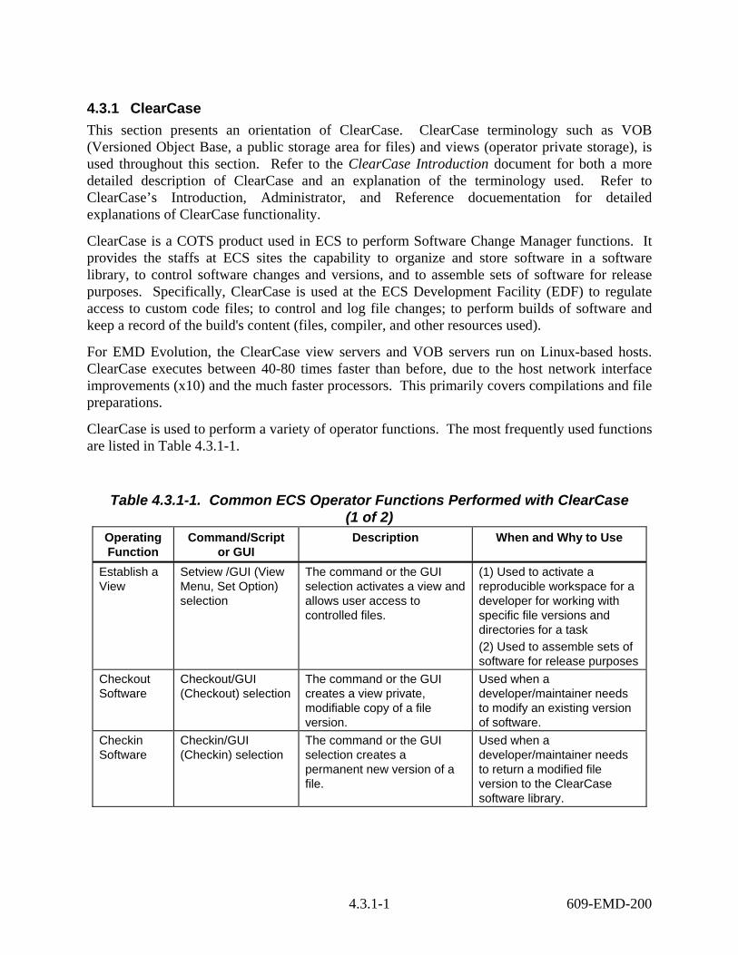
ClearCase is used to perform a variety of operator functions. The most frequently used functions are listed in Table 4.3.1-1.
Table 4.3.1-1. Common ECS Operator Functions Performed with ClearCase (1 of 2)
Operating Function
Command/Script or GUI
Description When and Why to Use
Establish a View
Setview /GUI (View Menu, Set Option) selection
The command or the GUI selection activates a view and allows user access to controlled files.
(1) Used to activate a reproducible workspace for a developer for working with specific file versions and directories for a task (2) Used to assemble sets of software for release purposes
Checkout Software
Checkout/GUI (Checkout) selection
The command or the GUI creates a view private, modifiable copy of a file version.
Used when a developer/maintainer needs to modify an existing version of software.
Checkin Software
Checkin/GUI (Checkin) selection
The command or the GUI selection creates a permanent new version of a file.
Used when a developer/maintainer needs to return a modified file version to the ClearCase software library.
4.3.1-1 609-EMD-200

Table 4.3.1-1. Common ECS Operator Functions Performed with ClearCase (2 of 2)
Operating Function
Command/Script or GUI
Description When and Why to Use
Perform software builds
Clearmake/GUI (Building menu)
(1) ClearCase build utility that automates the process of software builds (2) Facilitates derived object sharing (3) Creates a record of the build so that it can be repeated
Used when it’s time to build, integrate and/or test developed/revised software.
Display the mount-point and storage directory of all VOBs on the system
Cleartool lsvob/GUI (Admin menu)
ClearCase utility that determines and displays default/specified information about all of the VOBs that have been established.
(1) Used to list one or more VOBs (2) Used to determine which VOBs are mounted (3) Used to determine which VOBs are private or public (refer to ClearCase Reference Manual for details)
4.3.1.1 Quick Start Using ClearCase To invoke the ClearCase graphical user interface GUI from the command line prompt type:
/usr/atria/bin/xclearcase.
4.3.1.2 ClearCase Graphical User Interface ClearCase has a Command Line Interface (CLI) and a GUI. The GUI enables execution of all the common functions and facilitates graphical examination of the version history of objects in VOBs. When ClearCase is invoked, a Transcript screen as shown in Figure 4.3.1-1 appears. The Transcript screen displays status of functions executed and displays warning and error messages. It automatically appears when the status of an activity needs to be displayed.
Figure 4.3.1-1. ClearCase Transcript Screen
4.3.1-2 609-EMD-200

4.3.1.2.1 Establish View Operator access to versions of files in a VOB is facilitated by a view. When ClearCase is initiated, the operator is asked to select a view. Available views are displayed in the View Tag Browser Screen as shown in Figure 4.3.1-2. Select a view by highlighting the desired view and clicking the “Ok” button at the bottom of the screen.
Figure 4.3.1-2. View Tag Browser Screen
After a View is selected the ClearCase File Browser screen, the main GUI screen, appears as shown in Figure 4.3.1-3. The File Browser screen displays the current directory name just below the toolbar and displays the contents of the directory in the space below the directory’s name. A
4.3.1-3 609-EMD-200

variety of GUI-oriented functions can be initiated from this screen. Explanations of the menu bar and the toolbar items are provided in Chapter 3 of the ClearCase User’s Manual.
Figure 4.3.1-3. ClearCase File Browser Screen (Main Screen)
4.3.1.2.2 Checkout Software Software file versions in a ClearCase VOB are in a read-only state. An operator must check a file version out of the VOB before any editing of the file version can be accomplished. Check
out a file version by selecting the file and clicking the checkout icon on the toolbar. An alternate method is to select the file, click the Versions menu, then the Checkout option, then one of the “Reserved or Unreserved” options shown in Figure 4.3.1-4.
4.3.1-4 609-EMD-200
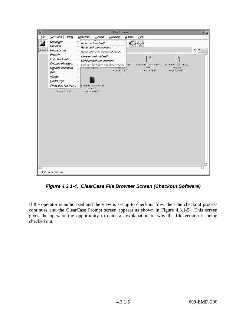
Figure 4.3.1-4. ClearCase File Browser Screen (Checkout Software)
If the operator is authorized and the view is set up to checkout files, then the checkout process continues and the ClearCase Prompt screen appears as shown in Figure 4.3.1-5. This screen gives the operator the opportunity to enter an explanation of why the file version is being checked out.
4.3.1-5 609-EMD-200
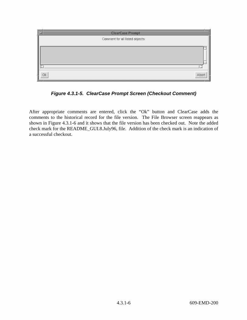
Figure 4.3.1-5. ClearCase Prompt Screen (Checkout Comment)
After appropriate comments are entered, click the “Ok” button and ClearCase adds the comments to the historical record for the file version. The File Browser screen reappears as shown in Figure 4.3.1-6 and it shows that the file version has been checked out. Note the added check mark for the README_GUI.8.July96, file. Addition of the check mark is an indication of a successful checkout.
4.3.1-6 609-EMD-200
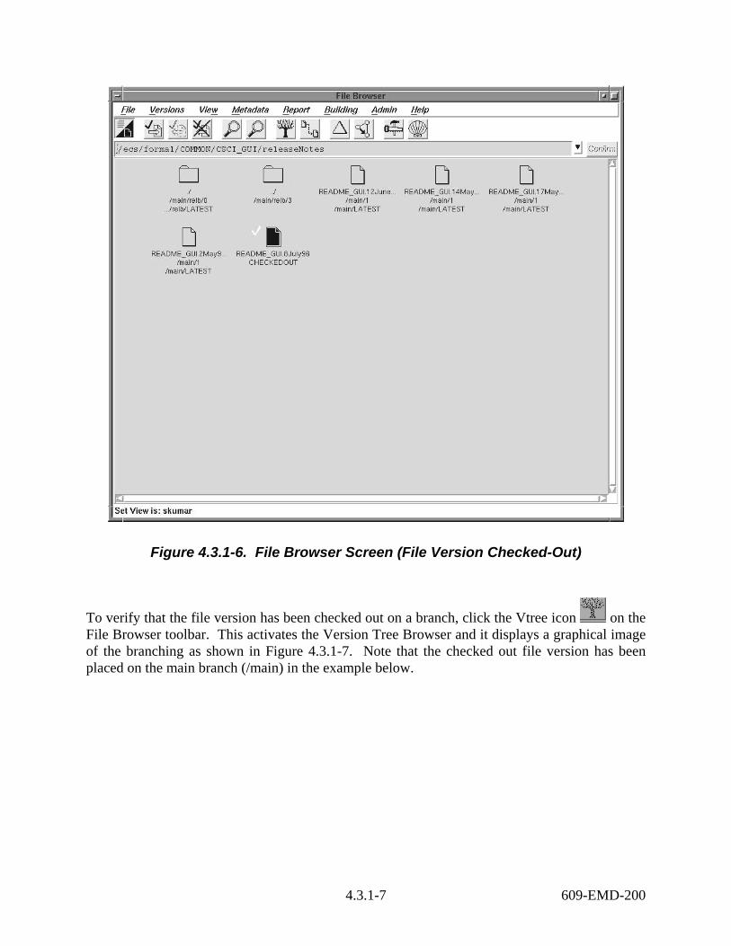
Figure 4.3.1-6. File Browser Screen (File Version Checked-Out)
To verify that the file version has been checked out on a branch, click the Vtree icon on the File Browser toolbar. This activates the Version Tree Browser and it displays a graphical image of the branching as shown in Figure 4.3.1-7. Note that the checked out file version has been placed on the main branch (/main) in the example below.
4.3.1-7 609-EMD-200
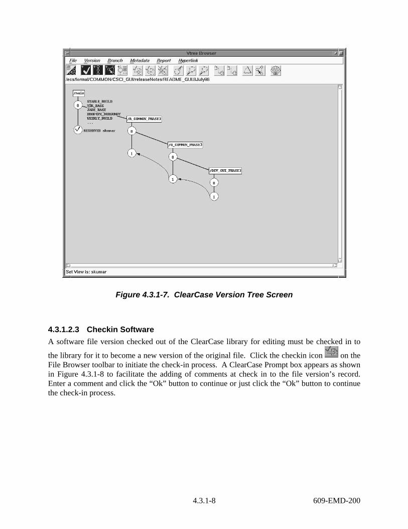
Figure 4.3.1-7. ClearCase Version Tree Screen
4.3.1.2.3 Checkin Software A software file version checked out of the ClearCase library for editing must be checked in to
the library for it to become a new version of the original file. Click the checkin icon on the File Browser toolbar to initiate the check-in process. A ClearCase Prompt box appears as shown in Figure 4.3.1-8 to facilitate the adding of comments at check in to the file version’s record. Enter a comment and click the “Ok” button to continue or just click the “Ok” button to continue the check-in process.
4.3.1-8 609-EMD-200

Figure 4.3.1-8. ClearCase Prompt Screen (Checkin Comment)
The File Browser screen reappears as shown in Figure 4.3.1-9 and it shows that the file version has been checked in. Note that the check mark that was next to the README_GUI.8July96 file has been removed. Removal of the check mark is an indication of a successful checkin.
4.3.1-9 609-EMD-200

Figure 4.3.1-9. ClearCase File Browser Screen (File Checked-In)
4.3.1.2.4 Perform Build The Building menu on the File Browser as shown in Figure 4.3.1-10 is used to produce derived objects. The Building menu is the GUI version of the command line interface build utility called clearmake. Reference the ClearCase Introduction and the clearmake section of the ClearCase Command Reference documents for information on the use of this capability.
4.3.1-10 609-EMD-200
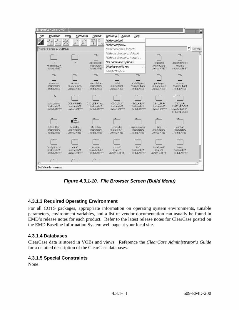
Figure 4.3.1-10. File Browser Screen (Build Menu)
4.3.1.3 Required Operating Environment For all COTS packages, appropriate information on operating system environments, tunable parameters, environment variables, and a list of vendor documentation can usually be found in EMD’s release notes for each product. Refer to the latest release notes for ClearCase posted on the EMD Baseline Information System web page at your local site.
4.3.1.4 Databases ClearCase data is stored in VOBs and views. Reference the ClearCase Administrator’s Guide for a detailed description of the ClearCase databases.
4.3.1.5 Special Constraints None
4.3.1-11 609-EMD-200
4.3.1.6 Outputs Reference the ClearCase Command Reference document for a description of the ClearCase outputs.
4.3.1.7 Event and Error Messages ClearCase creates an event record for most of the processing activities that modify the VOB and stores it in the VOB database. These records are linked to the derived objects. These records provide a chronological event history for the objects. Reference the ClearCase Reference Manual for detailed information about logging of ClearCase events. The reference manual describes the contents of an event record, VOB objects that have event histories, and ClearCase operations that cause event records to be written. ClearCase error messages indicate that a problem has occurred. Some errors are user correctable and others require correction by the operations staff. In both cases, ClearCase records error and status information in its log files. Reference the ClearCase Reference Manual for a description of the error logs, the ClearCase programs that use them, the error logs location, and their format.
4.3.1.8 Reports None.
4.3.1-12 609-EMD-200

4.3.2 Clear Distributed Defect Tracking System (CDDTS)
Deleted. Not applicable to Release 7.21.
4.3.2-1 609-EMD-200

This page intentionally left blank.
4.3.2-2 609-EMD-200
4.3.3 ClearCase Baseline Manager (BLM) ClearCase BLM is a custom application specifically designed to serve as an efficient configuration management tool to manage the EMD Baseline. It generates and maintains records that describe what comprises baselined operational system configurations for the DAACs, SMC, VATC, PVC, and the EDF2 Evolution hosts at the ECS Development Facility (EDF). These records identify baselined versions of hardware and software items as well as their assembly structures and interdependencies. ClearCase BLM keeps chronological histories of baseline changes and traceability of items to predecessor versions and system releases. In addition, the tool provides visibility to CCR approved baseline changes, as well as references to associated Release Notes documents.
ClearCase BLM does this by maintaining a set of ClearCase version-controlled elements along with scripts and internal information about how they relate. Control item records represent physical resources such as COTS software and host names assembled to form operational systems, as well as logical artifacts such as baselines and other configuration items. They are designated to relate system entities directly to discrete responsibilities and actions associated with configuration management of the system. ClearCase BLM’s catalog of control items is called the /ecs/cm/CIDs directory record set. The ClearCase BLM tool is an enhanced ClearCase GUI that uses the power of the ClearCase code management system to manage the GUI scripts, records, and scripts used to manage the baseline. Baseline records can only be affected with approved CCRs.
The most significant relationship maintained among control items is product structure. Product structure is the term for the ClearCase BLM data constructs that define the ingredients – or bill of material -- for a site. Product structures have corresponding CCR approval dates that establish the baseline change effectivity dates, and they reference CCRs numbers, as well as Release Notes.
ClearCase BLM is installed only at the EDF in Riverdale, MD, where it is used by CM personnel to manage baseline data about resources deployed to all external ECS sites, including the DAACs and the SMC, as well as the three internal ECS sites, the PVC, VATC, and the EDF2 string (Evolution). The EMD Baseline Information System (EBIS) is available to the Riverdale staff at URL http://pete.hitc.com/baseline/. Also, each site has an EBIS that is served locally. These EBIS sites are served from m0mss16, e0ins01, l0ins01, and n0ins02. Each site manages access to their EBIS file system. In the course of baseline updates, the data is replicated from “pete” to the other 4 EBIS servers. Each site offers a consolidated view of baseline data system-wide, as well as site-specific views. ClearCase BLM generates specific baseline reports that can be viewed, printed, or saved in a file. These reports are automatically formulated, posted to “pete”, and then replicated to the external servers. As part of Evolution, the Solaris 8 host “pete.hitc.com” has been replaced by Linux host “c4cbl02.hitc.com”. To maintain transparency to users, an alias was created so that the usual EBIS URL could be used. The Riverdale EBIS, though, is now served from Linux host “c4cbl02.hitc.com”.
4.3.3-1 609-EMD-200
4.3.3.1 Internal ClearCase BLM Data Constructs The ECS baseline data for COTS S/W, COTS S/W patches, Operating Systems, O/S patches, data files, databases, ECS hosts and host functions, resides in ClearCase as “text_file” elements. A default configuration specification is used to view the information, using the CM_MASTER view tag name.
A variety of files and methods hold this information, which are explained in detail below. Note that the architecture of the data design portion of ClearCase BLM minimizes the number of steps to update the baseline, by either implementing new CCRs or correcting previously entered CCR data.
There are 10 data constructs described below. One or more constructs is referenced by scripts in order to generate the specific Baseline Reports.
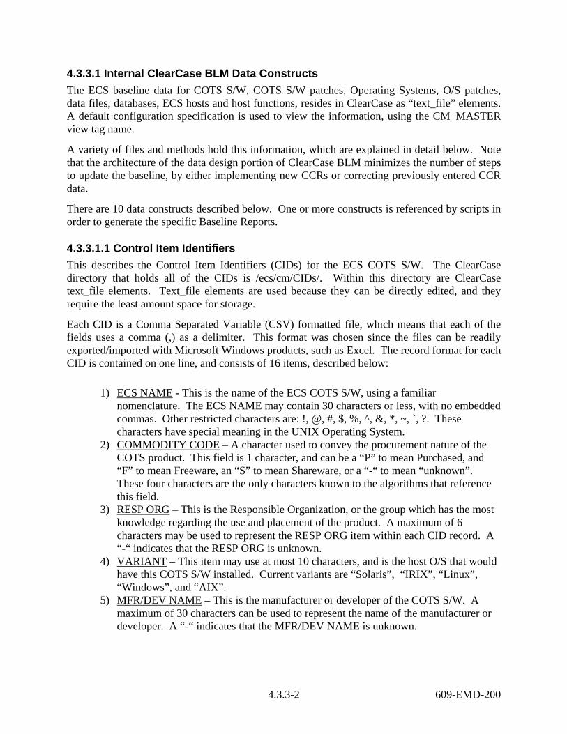
4.3.3.1.1 Control Item Identifiers This describes the Control Item Identifiers (CIDs) for the ECS COTS S/W. The ClearCase directory that holds all of the CIDs is /ecs/cm/CIDs/. Within this directory are ClearCase text_file elements. Text_file elements are used because they can be directly edited, and they require the least amount space for storage.
Each CID is a Comma Separated Variable (CSV) formatted file, which means that each of the fields uses a comma (,) as a delimiter. This format was chosen since the files can be readily exported/imported with Microsoft Windows products, such as Excel. The record format for each CID is contained on one line, and consists of 16 items, described below:
1) ECS NAME - This is the name of the ECS COTS S/W, using a familiar nomenclature. The ECS NAME may contain 30 characters or less, with no embedded commas. Other restricted characters are: !, @, #, $, %, ^, &, *, ~, `, ?. These characters have special meaning in the UNIX Operating System.
2) COMMODITY CODE – A character used to convey the procurement nature of the COTS product. This field is 1 character, and can be a “P” to mean Purchased, and “F” to mean Freeware, an “S” to mean Shareware, or a “-“ to mean “unknown”. These four characters are the only characters known to the algorithms that reference this field.
3) RESP ORG – This is the Responsible Organization, or the group which has the most knowledge regarding the use and placement of the product. A maximum of 6 characters may be used to represent the RESP ORG item within each CID record. A “-“ indicates that the RESP ORG is unknown.
4) VARIANT – This item may use at most 10 characters, and is the host O/S that would have this COTS S/W installed. Current variants are “Solaris”, “IRIX”, “Linux”, “Windows”, and “AIX”.
5) MFR/DEV NAME – This is the manufacturer or developer of the COTS S/W. A maximum of 30 characters can be used to represent the name of the manufacturer or developer. A “-“ indicates that the MFR/DEV NAME is unknown.
4.3.3-2 609-EMD-200
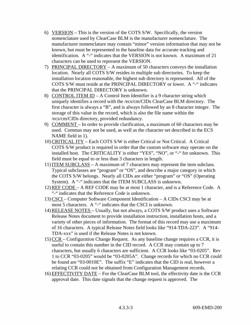
6) VERSION – This is the version of the COTS S/W. Specifically, the version nomenclature used by ClearCase BLM is the manufacturer nomenclature. The manufacturer nomenclature may contain “minor” version information that may not be known, but must be represented in the baseline data for accurate tracking and identification. A “-“ indicates that the VERSION is not known. A maximum of 21 characters can be used to represent the VERSION.
7) PRINCIPAL DIRECTORY – A maximum of 50 characters conveys the installation location. Nearly all COTS S/W resides in multiple sub directories. To keep the installation location reasonable, the highest sub directory is represented. All of the COTS S/W must reside at the PRINCIPAL DIRECTORY or lower. A “-“ indicates that the PRINCIPAL DIRECTORY is unknown.
8) CONTROL ITEM ID – A Control Item Identifier is a 9 character string which uniquely identifies a record with the /ecs/cm/CIDs ClearCase BLM directory. The first character is always a “B”, and is always followed by an 8 character integer. The storage of this value in the record, which is also the file name within the /ecs/cm/CIDs directory, provided redundancy.
9) COMMENT – In order to provide clarification, a maximum of 60 characters may be used. Commas may not be used, as well as the character set described in the ECS NAME field in 1).
10) CRITICAL ITY – Each COTS S/W is either Critical or Not Critical. A Critical COTS S/W product is required in order that the custom software may operate on the installed host. The CRITICALITY is either “YES”, “NO”, or “-“ for unknown. This field must be equal to or less than 3 characters in length.
11) ITEM SUBCLASS – A maximum of 7 characters may represent the item subclass. Typical subclasses are “program” or “OS”, and describe a major category in which the COTS S/W belongs. Nearly all CIDs are either “program” or “OS” (Operating System). A “-“ indicates that the ITEM SUBCLASS is unknown.
12) REF CODE – A REF CODE may be at most 1 character, and is a Reference Code. A “-“ indicates that the Reference Code is unknown.
13) CSCI – Computer Software Component Identification – A CIDs CSCI may be at most 5 characters. A “-“ indicates that the CSCI is unknown.
14) RELEASE NOTES – Usually, but not always, a COTS S/W product uses a Software Release Notes document to provide installation instruction, installation hosts, and a variety of other pieces of information. The format of this record may use a maximum of 16 characters. A typical Release Notes field looks like “914-TDA-223”. A “914-TDA-xxx” is used if the Release Notes is not known.
15) CCR – Configuration Change Request. As any baseline change requires a CCR, it is useful to contain this number in the CID record. A CCR may contain up to 7 characters, but usually 6 characters are sufficient. A CCR looks like “03-0205”. Rev 1 to CCR “03-0205” would be “03-0205A”. Change records for which no CCR could be found are “03-0010E”. The suffix “E” indicates that the CID is real, however a relating CCR could not be obtained from Configuration Management records.
16) EFFECTIVITY DATE – For the ClearCase BLM tool, the effectivity date is the CCR approval date. This date signals that the change request is approved. The
4.3.3-3 609-EMD-200

EFFECTIVITY DATE may contain a maximum of 8 characters, and is of the format mm/dd/yy, e.g., “03/28/03”.
All ClearCase BLM CIDs originated from XRP-II BLM CIDs. The CID format originated from XRP-II. In order to check the XRP-II data export into ClearCase BLM, the CID nomenclature was kept identical.
4.3.3.1.2 Current Hosts List The Current Hosts list contains all of the ECS baseline hosts. The ClearCase path is “/ecs/cm/host_data/current_hosts”. The UNIX file date for this file is the timestamp to indicate when the file was last changed.
There are as many lines to the file as there are current hosts. There are four fields within each record. Column 1 is the ECS host name. Column 2 is the ECS sub system to which the ECS host belongs. Column 3 is the CSCI for the ECS host, and column 4 is the ECS host major function.
1) ECS Host Name – This is the string returned from “uname –n” while logged onto the ECS host. Host name formats are 7 letters, generally. The first letter designates the ECS site, “e” for EDC, or LP DAAC, “g” for GSFC, “l” for LaRC, “n” for NSIDC, “m” for SMC, “p” for PVC, and “t” or VATC. Also, the letters “c”, “d”, “f”, and “i” designate the new Landover Linux Evolution hosts. (e.g., “c4cbl01”)
2) ECS Host Subsystem – This is the ECS functional component. The sub system name is three letters followed by the word “Subsystem”. The second column is always exactly 13 characters long, e.g “AST Subsystem”.
3) CSCI – A specific set of up to 5 characters which identify the Computer Software Component Identification.
4) ECS Host Major Function – Each ECS host exists for a purpose. The purpose is stated in column 4 of this construct, and may contain a maximum of 30 characters.
4.3.3.1.3 Data List In order to emulate the earlier XRP-II reports, this construct was created. There are two entities that are present in the reports, “data” and “databases”. The Data List construct exists to provide the “data”. This construct path is /ecs/cm/BLM/host_data/data, and is a Clearcase text_file element that is directly editable. It is a CSV formatted file.
Each record (line) within this file is comprised of 7 fields: 1) ECS Host Name – This is the name of the hosts, e.g., “e4eil01”. The name can be a
maximum of 10 characters. 2) Data Name – This is the data that is conveyed by the Construct. A typical data name
is “Production data”, or “Ingest files”. The Data Name can have a maximum of 50 characters.
3) Data Version – This is the version of the Data Name. This can be at most 7 characters, and represents the major version of the data, such as “6A”.
4) Data Construct Type – For this construct, the fourth field must always say “data”.
4.3.3-4 609-EMD-200

5) Data CID – Data Control Item Identifier. This field has a CID format entry, and has to be exactly 9 characters in length.
6) Data CSCI – Computer Software Component Identification – A CSCI may be at most 5 characters.
7) Data Responsible Organization – The cognizant ECS organization for the data; the owner of the data. This field may be a maximum of 6 characters.
4.3.3.1.4 Databases List In order to emulate the XRP-II reports, this construct was created. There are two entities that are present in the reports, “data” and “databases”. The Databases List construct exists to provide the “databases.” This construct path is /ecs/cm/BLM/host_data/databases, and is a Clearcase text_file element that is directly editable. It is a CSV formatted file.
Each record (line) within this file is comprised of 8 fields: 1) ECS Host Name – This is the name of the hosts, e.g., “e4eil01”. The ECS Host Name
name can be a maximum of 10 characters. 2) Database Name – This is the data that is conveyed by the Construct. Database name
examples are “Autosys DB”, or “DDTS db”. The Database Name can have a maximum of 50 characters.
3) Database Version – This is the version of the Database Name. This can be at most 7 characters, and represents the major version of the database, such as “6A”.
4) Database Construct Type – For this construct, the fourth field must always say “database”.
5) Database CID – Database Control Item Identifier. This field has a CID format entry, and has to be exactly 9 characters in length.
6) Database Code – A single character, either blank, or the letter “I”. 7) Data CSCI – Computer Software Component Identification – A CSCI may be at most
5 characters. 8) Data Responsible Organization – The cognizant ECS organization for the database;
the owner of the database. This field may be a maximum of 6 characters.
4.3.3.1.5 Hosts’ Functions List In order to emulate the earlier XRP-II reports, this list was created. In the ClearCase BLM 920-TDx-002 Hardware/Software Map reports, there may be a few lines, just after the host name, that describe more host attributes, or functions, such as ” FLEXlm License Server”, or “NIS Master Server”. This construct path is /ecs/cm/BLM/host_data/host_functions, and is a Clearcase text_file element that is directly editable. Each record consists of two column groupings.
Each record (line) within this file is comprised of the following: 1) ECS Host Name – This is the name of the host, e.g., “e4eil01”. The ECS host name
can be a maximum of 10 characters. The ECS host name must begin in column 1. 2) Host Function – This is a text string with a maximum of 50 characters. This
descriptive text provides information regarding host functionality. The Host Function text must begin in column 14, in order for the data to align correctly in the reports. Embedded commas are permitted in this construct.
4.3.3-5 609-EMD-200

Note that the spacing of the host name and the text appears in the record lines exactly as in the output 920-TDx-002 reports. No reformatting of the data is performed in the generation of the reports.
4.3.3.1.6 Control Item Identifier Type List In order to emulate the original 910-TDA-003 report, another piece of information is required. This is the category to which the CID belongs. Examples of these CID functional groupings are: Compilers, Editing & Viewing, Operating Systems, and the like.
Each record of this file consists of two column groupings: 1) Functional Group Name – The first character of the string must be placed in column
1. The string length may be up to 38 characters. 2) CID – Control Item Identifier number. This number must exist with the
/ecs/cm/CIDs directory, described above as Data Construct 1. The 9 character CID must begin in column 39.
4.3.3.1.7 Operating System Patch Sets Patch_sets are described in this section. These are sets of information, residing in the directory /ecs/cm/BLM/patch_sets/. There are about 20 patch sets that are named according to their function. A patch set name may be up to 30 characters in length. An example Patch Nomenclature name is “IRIX_core”. Each line within a patch set (record) is comprised of 6 column groupings, and are described below:
1) Patch Nomenclature – This is a name of the patch set. The string must start in column 4, and may use up to column 27, for a total maximum character length of 24 characters.
2) Patch Description – A comment-like character string that adds information value and detail to the Patch Nomenclature. This data must start in column 29 and be complete by column 83 (or a maximum string length of 55 characters).
3) Patch reference – With each patch release, there is a related Release Notes Technical Document, e.g., 914-TDA-087, or a related Patch Technical Document, such as 911-TDA-011. This field begins in column 85 and is 16 characters in length (to column 101).
4) CCR – This is the CCR number which authorized the patch set’s placement in the ECS baseline. Columns 107 through 114 house the CCR number.
5) Release Notes tech doc - With each patch release, there is a related Release Notes Technical Document, e.g., 914-TDA-087. This field begins in column 118 and is 16 characters in length (to column 133).
6) ECS Subsystem – Up to three characters long, this field relates the patch information to the cognizant sub system, such as “IDG”.
Note that the column positions are critical; the generated 920-TDx-014 Patch Maps take these records and directly import them into the records with no reformatting.
With the introduction of the Linux Operating System, all RPMs (Package Manager) are now baselined. These are the functional equivalents to the Solaris 8 and IRIX Operating System
4.3.3-6 609-EMD-200

patches. Please reference the new Technical Document 911-TDA-014, for example, to view the Linux method for patching the Operating System.
4.3.3.1.8 Configuration Change Request (CCR) Data The ClearCase BLM Tool relates all change requests to the items changed, including an effectivity date. This date is the effective date for which the change pertains. CCR information is stored in Data Construct 8. This construct exists as directory /ecs/cm/CM. Under this directory are sub directories, one for each year for the CCRs. For the year 2003, the sub directory name is 2003_CCRs. So any 2003 year CCRs are found in the path: /ecs/cm/CM/2003_CCRs/.
For each CCR, another sub directory exists, which consists of the last four digits of the CCR, or five digits if the CCR has been revised, like “0188A”. The first two digits of the CCR represent the year. So for the example of the CCR 03-0188A, a directory /ecs/cm/CM/2003_CCRs/0188A/. exists. Data Construct 8 is probably the most important of all the Data Constructs, as it provides the relations of the CIDs to the ECS hosts. For each CCR sub directory, there are the following sub constructs:
1) “CID_map” file – This file, always named “CID_map”, provides the relations of the Machine Impacted file(s) (MI) to the CIDs. It always has at least one line, but may contain more than one line, as a single CCR may relate more than one CID to a host set (MI) file. It has two columns. The first column is the name of an “MI” file, up to 20 characters in length.
2) “MI” file(s) – This is an abbreviation for the “Machines Impacted” file. The source of this information is derived from the CCR’s Release Notes document (914-TDA-xxx). Within the Release Notes document is a section that describes which hosts should receive what COTS S/W. Most CCRs have a CID_map file with only one MI and CID. The next most common arrangement is to have two variants, a Linux and a Sun variant. In this case there are two lines in the CID_map file. One line, MI_Sun, maps to the Sun variant of the CID. The other line maps the MI_Linux to the Linux CID for the CCR.
3) CCR pdf file – This file is the Portable Data Format (Adobe) CCR.
4.3.3.1.9 ClearCase BLM Sequencer A single file, “/ecs/cm/BLM/scripts/Sequencer”, controls which CCRs are applied to the baseline, and in what order. This editable yet executable file provides the mechanism for relating the application of CCRs, their MI files and CID_maps, to populate what is known as the “dartboard” area. The first record in this file applies the first CCR to a “null,” or empty baseline. The last record applies the last CCR to the “dartboard”. The format of each record of this file is:
1) Function Call – This is always the same string, “/ecs/cm/BLM/scripts/Implement_CCR”. This function applies the first argument of the call, which is the CCR, to the “dartboard”.
2) CCR – Configuration Change Request. A number that identifies a change to a baseline. It authorizes the application of a COTS S/W product to an ECS host or set of ECS hosts.
4.3.3-7 609-EMD-200

3) Comment 1 – This comment is the “function”, or COTS S/W name, of the CCR. 4) Comment 2 – The CCR approval date (Effectivity Date) 5) Comment 3 – This is the Release Notes Tech Doc number, which is referred to in the
CCR.
4.3.3.1.10 ClearCase BLM Dartboard The ClearCase Derived Objects, located within the “/ecs/formal/BLM/dartboard” directory, comprise the Dartboard. This directory contains one file representing the collective assembly of all applicable COTS S/W products as authorized by approved CCRs for each ECS host. COTS S/W application is performed by using file concatenation. The first CCRs (earliest) show up first in these dartboard files. The last applied CCR shows up as the last record in these files.
Each dartboard file name is an ECS host, like “e4eil01”.
The format of each line in a host dartboard file is as follows: 1) ECS host name – This is the ECS host name. 2) Authorizing CCR – This is the CCR from the Sequencer file. 3) BLM Tool user – This is an authorized User of the ClearCase BLM tool. 4) Timestamp – This is the time at which the CCR was applied to the file in the
dartboard. 5) CID Echo – This is the entire contents of the CID record, as specified by the CCR’s
CID_map, MI files, and CID reference. Note that Data Construct 10 is a ClearCase derived object, and is not “checked-in” like the first Data Constructs. The dartboard directory, in conjunction with the “/ecs/cm/BLM/host_data/current_hosts” file, is used to populate the 920-TDx-002 Hardware Software Map Technical Documents.
4.3.3.2 ClearCase BLM Graphical User Interface (GUI) The ClearCase BLM tool makes use of an OSF Motif graphical user interface. This provides convenient drop down menus, and provides a convenient method for dynamically formulating the contents of the drop down menus. The ClearCase BLM tool has been ported to the Linux operating system. It may be launched on Linux host “c4cbl01.” The GUI now uses “emacs” for certain text editing windows, rather than Solaris 8 “textedit.”
4.3.3.2.1 ClearCase BLM “New CCR” GUI Drop Down Menu Use the “New_CCR” ClearCase BLM Tool GUI to enter data associated with newly approved CCRs. The amount of GUI traversal and data input has been optimized to minimize the time needed to process approved CCRs. Refer to Figure 4.3.3-1 to view the New CCR drop down menu.
The first thing to do is to enter the new CCR number. A quick check is made to ensure that the CCR number is indeed a new CCR number, one that does not exist in the database. Extensive syntax checking is performed to ensure that the entered CCR number is of the correct format and has the hyphen character. See Figures 4.3.3-2 through 4.3.3-9 for the new CCR entry user interface and subsequent screens.
4.3.3-8 609-EMD-200

The next set of steps taken depends on the nature of the CCR. A COTS S/W CCR will only affect the 920-TDx-002 Maps for instance, while O/S patch changes will affect the 920-TDx-014 reports.
For COTS S/W changes, a new CID usually needs to be created. Use the “Construct new CID” menu item in the “New_CCR” main menu bar to construct the new CID. Script has been written to easily perform this task. Usually and existing CID can be copied, and only minor adjustments made, such as the CCR approval date or Release Notes document number, and usually the COTS S/W version number. This CID is then “committed” to the database (/ecs/cm/CIDs), and is later referenced in the CID_map file for the new CCR.
Also, a Machines Impacted (MI) will need to be created. This MI file and the new CID will be associated in the CID_map file. Depending on the CCR, more than one MI file linking with another new CID may be required. Perform these steps as needed, then commit the CCR as the last step. Committing the CCR will checkin the CID_map file, any new MI files, and finally the CCR itself.
The Sequencer is then updated. Usually the CCR is added to the end of the Sequencer. Sometimes, earlier entries or CCR constructs may need to be edited, so that more than one version of a COTS product will not appear in the 920-TDx-002 reports.
Other less frequently used data may need to be altered, and this just depends on the nature of the CCR. To remove an ECS host for example, select the “Update Current ECS Hosts” menu line item, and delete the ECS host. If a new CID is added to the database, its function must also be added using the “Update CID Functions” line item.
Selecting the “Build Baseline” line item will generate all of the ClearCase BLM reports, and selecting the “Promote Baseline” line item will place all of the reports in the proper directories on “pete” and “cmdm”. These two functions save hours of labor and ensure a consistent product.
4.3.3-9 609-EMD-200

Figure 4.3.3-1. New CCR Drop Down Menu
4.3.3-10 609-EMD-200

Figure 4.3.3-2. Entering a New CCR Number
4.3.3-11 609-EMD-200

Figure 4.3.3-3. Working Record Contents for a New CCR
4.3.3-12 609-EMD-200

Figure 4.3.3-4. New CCR Drop Down with Construct New CID Selected
4.3.3-13 609-EMD-200

Figure 4.3.3-5. View CIDs by Name Drop Down Sequence
4.3.3-14 609-EMD-200
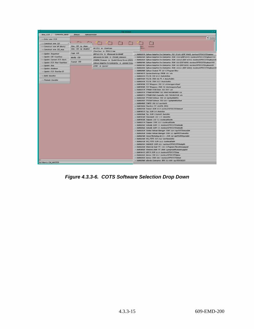
Figure 4.3.3-6. COTS Software Selection Drop Down
4.3.3-15 609-EMD-200

Figure 4.3.3-7. SGI Tripwire COTS S/W Selection
4.3.3-16 609-EMD-200

Figure 4.3.3-8. Working Record Contents Up
4.3.3-17 609-EMD-200

Figure 4.3.3-9. All ECS Tripwire SGI Hosts
4.3.3.2.2 ClearCase BLM “CORRECTIVE MODE” GUI Drop Down Menu Figure 4.3.3-10 shows the ClearCase BLM Tool mode drop down that is used for correcting information that has already been entered for an approved CCR. The basic steps are:
1) Select an existing CCR number 2) Alter the data 3) Either COMMIT the changes, or CANCEL the changes 4) Build the baseline, incorporating the changed data, if COMMITted 5) Promote the baseline, after ensuring that the changes were made as intended
4.3.3-18 609-EMD-200

Figure 4.3.3-10. Corrective Mode Drop Down Menu
An error will be returned if the CCR does not exist in the ClearCase data structures.
The design intention of this mode was to allow corrections to data that had already been entered. In order to get the ECS baseline data corrected, it was necessary to allow controlled editing of historical files, including the CID_map, any Machines Impacted (MI) files, and any associated Control Item Identifier (CID) records.
Each approved CCR has only one CID_map. This correlates the MI files to the CID. Sometimes there are two variants (host types, like Linux and Sun) of COTS S/W which must be accounted. The CID_map would then have two lines, one MI file for Linux hosts (MI_Linux), and one MI file for Sun hosts (MI_Sun). There would also be two CIDs to account for the Linux and Sun variants. The CID_map would then relate the MI_Linux hosts to the Linux variant CID, and the MI_Sun hosts to the Sun variant CID.
Too often the original MI lists are wrong, that is, the hosts which were directed to get the COTS S/W from the CCR were missing hosts, or listed the wrong hosts. This mode allows for the correction of those files.
The snapshot below in Figure 4.3.3-11 shows the File Browser when CCR “03-0170” has been entered into the text edit window, just before the “save”/”exit”:
4.3.3-19 609-EMD-200

Figure 4.3.3-11. Enter Existing CCR Number Interface
The script will then determine the data structure for the entered CCR. The simplest structure will have one MI file. All CCRs will have the CID_map file. The most complex CCR is an “automount” CCR, where there are 12 different Machines Impacted files, placing 12 COTS S/W products according to the MI files.
CCR # 03-0170 was chosen for its simplicity. It only has one MI file, containing 18 ECS hosts representing EDC, GSFC, LaRC, NSIDC, and the PVC. The MI file is simply named “MI”, and it references CID “b00083923.”
Figure 4.3.3-12 on the next page shows the launch of three text edit windows. Each CCR will launch the CID_map file for the entered CCR. It is a square window, with one line for each MI/CID pairing.
Because of the nature of the files, the “MI” files are shown in columns, and the CIDs are shown as rows. CIDs are actually just one long line of characters, and the MI files may contain only one host, or more than a hundred hosts.
4.3.3-20 609-EMD-200
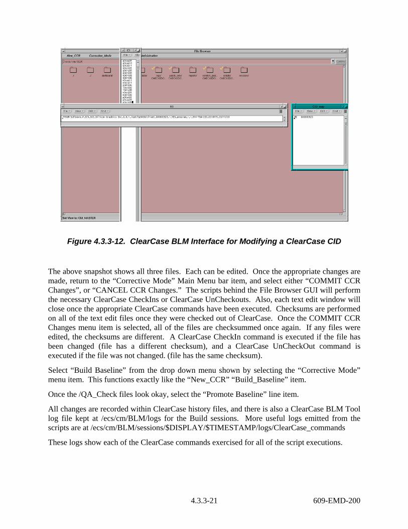
Figure 4.3.3-12. ClearCase BLM Interface for Modifying a ClearCase CID
The above snapshot shows all three files. Each can be edited. Once the appropriate changes are made, return to the “Corrective Mode” Main Menu bar item, and select either “COMMIT CCR Changes”, or “CANCEL CCR Changes.” The scripts behind the File Browser GUI will perform the necessary ClearCase CheckIns or ClearCase UnCheckouts. Also, each text edit window will close once the appropriate ClearCase commands have been executed. Checksums are performed on all of the text edit files once they were checked out of ClearCase. Once the COMMIT CCR Changes menu item is selected, all of the files are checksummed once again. If any files were edited, the checksums are different. A ClearCase CheckIn command is executed if the file has been changed (file has a different checksum), and a ClearCase UnCheckOut command is executed if the file was not changed. (file has the same checksum).
Select “Build Baseline” from the drop down menu shown by selecting the “Corrective Mode” menu item. This functions exactly like the “New_CCR” “Build_Baseline” item.
Once the /QA_Check files look okay, select the “Promote Baseline” line item.
All changes are recorded within ClearCase history files, and there is also a ClearCase BLM Tool log file kept at /ecs/cm/BLM/logs for the Build sessions. More useful logs emitted from the scripts are at /ecs/cm/BLM/sessions/$DISPLAY/$TIMESTAMP/logs/ClearCase_commands
These logs show each of the ClearCase commands exercised for all of the script executions.
4.3.3-21 609-EMD-200

4.3.3.2.3 ClearCase BLM “BROWSE” GUI Drop Down Menu This particular feature of the ClearCase BLM Tool was added late in the development of the tool. While using the tool, it became apparent that it would be useful to be able to “see” any of the data items tucked away in the tool’s repository.
There are 8 different items that can be observed using the “Browse” selection as shown in Figure 4.3.3-13. Each selection has a unique number of attributes that can be viewed. Windows are launched so that the GUI user can “see” the different data.
Figure 4.3.3-13. Browse Drop Down Menu
These drop down menus and data files are generated at the time that the GUI is launched, so it’s important to remember that newly added records will not appear in these windows.
In the example below, a ClearCase BLM Tool user wants to know what firmware exists within the ECS baseline.
To determine this, select “Browse” from the File Browser main menu bar, then select “Browse SUBCLASS”, then “for SUBCLASS = firmware”, as shown in Figure 4.3.3-14.
Alternatively, the user could select “Browse CID Functions”, then there would show 7 different types of firmware.
4.3.3-22 609-EMD-200

Figure 4.3.3-14. Browse Drop Down with SUBCLASS Selected
Selecting the “for SUBCLASS = firmware” line item will return the following information shown in Figure 4.3.3-15.
4.3.3-23 609-EMD-200

Figure 4.3.3-15. All ECS Firmware Products Selection
Similarly, any of the “Browse” drop down menu items may be selected.
4.3.3.2.4 ClearCase BLM “ADMINISTRATION” GUI Drop Down Menu The “Modify Users” line item under the “Administration” main menu bar enables one to add, modify, or remove a UNIX user. The ClearCase file which facilitates this function is /ecs/cm/BLM/scripts/authorized_DISPLAYs. Selecting the “Modify Users” line item initiates a text edit window session using the “authorized_DISPLAYs” file. The format of this file is as follows:
The first three lines of the file are comments that identify the file’s location.
The next items are constructs that enable the BLM tool to determine authorized users of the BLM tool, and also authorized terminals. Determination is done at the time the tool is launched.
Each construct must contain at least one line for each BLM tool user. Users may launch the tool from more than one location and terminal, which requires more than one line for the construct. There may be up to five fields within each line. Each field must not have any embedded spaces; spaces (blanks) are used to separate the fields. For readability, user constructs should be separated with blank lines.
4.3.3-24 609-EMD-200

The first field indicates the display nomenclature. For X terminals, this is the string representation of “ncdp10:0.0”, for example. This has to be the same string that is known as the DISPLAY environment variable. For PCs, this field needs to be set to the correct IP address associated with the PC. Note that the tool may be used remotely.
The second field contains the physical location of the terminal. This should be either “home” for off site usage, or the room or cubical number at Landover that contains the terminal.
The third field is the UNIX user. The UNIX user must be known to the EDF. The UNIX user format usually consists of the first letter of the first name of the user, followed by up to a maximum of 7 letters of the user’s last name, all lower case.
The fourth field indicates whether the terminal is a PC or an X terminal.
The fifth field contains the IP address resolution of the first field, if the first field is not already an IP address.
TO ADD A USER:
Add a construct to the end of the file with the above fields completed. To determine the first field (DISPLAY) on a PC, run “winipcfg” from the “Start”/”Run” window. It will return the PC’s IP address. To determine the first field (DISPLAY) on an X terminal, type “printenv DISPLAY”. It will return the value of the DISPLAY environment variable.
NOTE: A newly added user must also be added to the UNIX “ccs” group and UNIX “blm_tool” group. To determine whether a user is currently in the group, type “ypcat –k group | grep ccs” and “ypcat –k group | grep blm_tool”. Being a member of the “ccs” group gives one write access to ClearCase BLM records within the ClearCase /ecs/cm VOB. Being a member of the “blm_tool” group allows one to execute the ClearCase BLM scripts which are referenced by the ClearCase BLM GUI.
TO MODIFY A USER:
Simply edit the “authorized_DISPLAYs” file to include the correct information.
TO REMOVE A USER:
Simply delete all of the lines within the “authorized_DISPLAYs” that contains the user’s UNIX name.
Note that the tool needs to be re launched in order for any changes in the “authorized_DISPLAYs” file to take effect.
The following three snapshots show the screens that were just discussed:
4.3.3-25 609-EMD-200
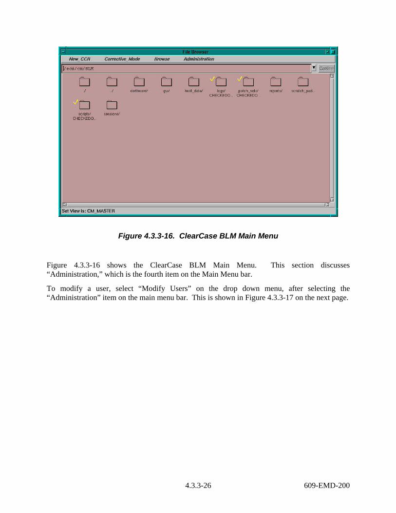
Figure 4.3.3-16. ClearCase BLM Main Menu
Figure 4.3.3-16 shows the ClearCase BLM Main Menu. This section discusses “Administration,” which is the fourth item on the Main Menu bar.
To modify a user, select “Modify Users” on the drop down menu, after selecting the “Administration” item on the main menu bar. This is shown in Figure 4.3.3-17 on the next page.
4.3.3-26 609-EMD-200

Figure 4.3.3-17. Administration Drop Down Menu
Selection of “Modify Users” will launch an x-term window. The file appears using “textedit” as the text editor. This is shown on the next page.
The text edit window in Figure 4.3.3-18 shows the file that can be edited.
4.3.3-27 609-EMD-200

Figure 4.3.3-18. Administration Modify Users Screen
Follow earlier instructions for changing users or user information.
4.3.3.3 ClearCase BLM Reports The reports that are generated using the ClearCase BLM tool are listed in Table 4.3.3-1.
Table 4.3.3-1. ClearCase BLM Reports 910-TDA-003 COTS S/W VERSION Baseline Report 910-TDA-005 SITE-HOST Map Report 910-TDA-023 CRITICAL COTS SOFTWARE LIST 910-TDA-030 COTS S/W Where-Used Reports 920-TDx-002 Site Hardware-Software Maps 920-TDx-014 Operating System Patch Maps
4.3.3-28 609-EMD-200

These reports are accessible at the URLs:
http://pete.hitc.com/baseline/ (Riverdale only)
http://m0mss16.ecs.nasa.gov:10160/baseline/ (SMC only)
http://e0ins01u.ecs.nasa.gov:10160/baseline/ (LPDAAC only) (aka EDC)
http://l0ins01u.ecs.nasa.gov:10160/baseline/ (ASDC only) (aka LaRC)
http://n0ins02u.ecs.nasa.gov:10160/baseline/ (NSIDC only)
The 910-TDA-003 report shows all of the COTS S/W that is managed on the EMD program. The software is ordered by the software function, such as “Compilers”. Each record entry lists the ECS NAME, the Commodity Code, the Responsible Organization, the Variant, the Manufacturer, the Version, the Principal Directory, the authorizing CCR, and any comments that may be needed for clarification. The report is generated when the “Build Baseline” line item is selected in the New_CCR drop down menu.
The 910-TDA-005 report shows all of the ECS hosts that are managed on the EMD program. The format of the file is a matrix, with the columns containing all of a site’s hosts, with the rows showing the host names, in addition to Host Functions, Sub systems, and SRC CIs.
The 910-TDA-023 report shows COTS software products’ criticality. A critical COTS product is defined as software whose removal from the host would cause the system to not function with respect to ECS custom code. A critical COTS product is designated by a "YES" in the first column below. A "NO" indicates that the COTS software product is not critical to the performance of the system's functions.
The 910-TDA-030 report allows a user to see all of the COTS S/W, and each host that should have it. A table containing links provides this information. For each COTS product, a link will provide the complete CID record for the product, as well as a matrix showing all of the ECS hosts. Those hosts which should have the product installed have an arrow next to each host name. These Where-Used reports are also used to provide input with new CCRs to affect changes to the baseline. Changes to the CID record, such as a new version, or new hosts, can be recorded and submitted using a mark up of this printout.
The 920-TDx-002 reports show the mapping of the COTS S/W to the managed ECS hosts. There are 8 reports, one for each site. Refer to Table 4.3.3-2.
4.3.3-29 609-EMD-200
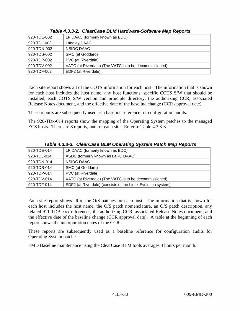
Table 4.3.3-2. ClearCase BLM Hardware-Software Map Reports 920-TDE-002 LP DAAC (formerly known as EDC) 920-TDL-002 Langley DAAC 920-TDN-002 NSIDC DAAC 920-TDS-002 SMC (at Goddard) 920-TDP-002 PVC (at Riverdale) 920-TDV-002 VATC (at Riverdale) (The VATC is to be decommissioned) 920-TDF-002 EDF2 (at Riverdale)
Each site report shows all of the COTS information for each host. The information that is shown for each host includes the host name, any host functions, specific COTS S/W that should be installed, each COTS S/W version and principle directory, the authorizing CCR, associated Release Notes document, and the effective date of the baseline change (CCR approval date).
These reports are subsequently used as a baseline reference for configuration audits.
The 920-TDx-014 reports show the mapping of the Operating System patches to the managed ECS hosts. There are 8 reports, one for each site. Refer to Table 4.3.3-3.
Table 4.3.3-3. ClearCase BLM Operating System Patch Map Reports 920-TDE-014 LP DAAC (formerly known as EDC) 920-TDL-014 ASDC (formerly known as LaRC DAAC) 920-TDN-014 NSIDC DAAC 920-TDS-014 SMC (at Goddard) 920-TDP-014 PVC (at Riverdale) 920-TDV-014 VATC (at Riverdale) (The VATC is to be decommissioned) 920-TDF-014 EDF2 (at Riverdale) (consists of the Linux Evolution system)
Each site report shows all of the O/S patches for each host. The information that is shown for each host includes the host name, the O/S patch nomenclature, an O/S patch description, any related 911-TDA-xxx references, the authorizing CCR, associated Release Notes document, and the effective date of the baseline change (CCR approval date). A table at the beginning of each report shows the incorporation dates of the CCRs.
These reports are subsequently used as a baseline reference for configuration audits for Operating System patches.
EMD Baseline maintenance using the ClearCase BLM tools averages 4 hours per month.
4.3.3-30 609-EMD-200

4.3.4 Remedy-ILM (Inventory, Logistics and Maintenance {ILM} Manager) ILM helps the DAACs and the EDF maintain records that describe all inventory items, as well as their EIN structures, repair histories, and locations. The system keeps chronological histories (a record of the transactions) of installation, relocation, movement, shipment and archiving of inventory items. ILM is used by the Property Management, Maintenance, and Logistics teams to support management of the tangible property of NASA’s EOSDIS project.
ILM is a customized application of the Remedy Action Request System (ARS). The customizations adapt the product to the ILS processes used for ECS. ILM takes into account how business rules and logistics concepts are applied on the ECS project. This document does not address these considerations in detail, but the following general introduction should help.
Each inventory item is identified by a unique Equipment Inventory Number (EIN). In the case of hardware items, an EIN corresponds to a silver sticker affixed to the item. Some of the items are shipped to sites and installed. Others such as consumables are issued but not installed. After a period, some items may be transferred to other locations or relocated for use with other parent machines. Items are archived when no longer needed or serviceable. For tracking and auditing purposes, inventory items – especially hardware – are allocated to ECS “parent” machines. These parent and child relationships are called an EIN structure. EIN structures have active and inactive dates that establish the timeframe during which the pairing is in effect.
Table 4.3.4-1 summarizes the operator functions that Remedy supports. The sections that follow present how to use Remedy features that were customized for ECS inventory, logistics, and maintenance management. For more information on Remedy’s Action Request System, refer to the Remedy help manual.
4.3.4-1 609-EMD-200
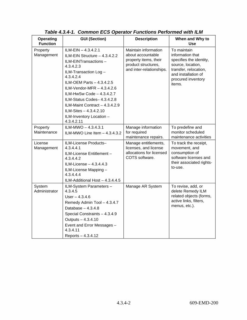
Table 4.3.4-1. Common ECS Operator Functions Performed with ILM Operating Function
GUI (Section) Description When and Why to Use
Property Management
ILM-EIN – 4.3.4.2.1 ILM-EIN Structure – 4.3.4.2.2 ILM-EINTransactions – 4.3.4.2.3 ILM-Transaction Log – 4.3.4.2.4 ILM-OEM Parts – 4.3.4.2.5 ILM-Vendor-MFR – 4.3.4.2.6 ILM-HwSw Code – 4.3.4.2.7 ILM-Status Codes– 4.3.4.2.8 ILM-Maint Contract – 4.3.4.2.9 ILM-Sites – 4.3.4.2.10 ILM-Inventory Location – 4.3.4.2.11
Maintain information about accountable property items, their product structures, and inter-relationships.
To maintain information that specifies the identity, source, location, transfer, relocation, and installation of procured inventory items.
Property Maintenance
ILM-MWO – 4.3.4.3.1 ILM-MWO Line Item – 4.3.4.3.2
Manage information for required maintenance repairs.
To predefine and monitor scheduled maintenance activities
License Management
ILM-License Products– 4.3.4.4.1 ILM-License Entitlement – 4.3.4.4.2 ILM-License – 4.3.4.4.3 ILM-License Mapping – 4.3.4.4.4 ILM-Additional Host – 4.3.4.4.5
Manage entitlements, licenses, and license allocations for licensed COTS software.
To track the receipt, movement, and consumption of software licenses and their associated rights-to-use.
System Administrator
ILM-System Parameters – 4.3.4.5 User – 4.3.4.6 Remedy Admin Tool – 4.3.4.7 Database – 4.3.4.8 Special Constraints – 4.3.4.9 Outputs – 4.3.4.10 Event and Error Messages – 4.3.4.11 Reports – 4.3.4.12
Manage AR System To revise, add, or delete Remedy ILM related objects (forms, active links, filters, menus, etc.).
4.3.4-2 609-EMD-200

4.3.4.1 Quick Start Using Remedy-ILM Operators use the PC_based Remedy User tool to access Remedy-ILM. They can login to Remedy User if they are registered in Remedy-ILM and are assigned an ILM-related role.
4.3.4.1.1 Invoking Remedy-ILM from a PC To start Remedy User, you can do one of the following: • Click Start Programs Action Request System Remedy User
• Double-click on a Remedy User icon on your desktop, if one exists.
The Remedy User screen displays. Enter your user Id and password.
Once logged into Remedy User, you can open a form. To view a list of all available forms, select File Open, or select the Open icon, the first icon in the toolbar. This displays the complete list of forms to which the operator have access (see Figure 4.3.4.1).
Figure 4.3.4-1. Open GUI
Every form has a specific layout and content. Every form initially opens in one of two modes:
• New – to create a new record
• Search – to search for an existing record
4.3.4-3 609-EMD-200
4.3.4.1.2 ILM-Roles The following are the ILM-related roles that Remedy is deployed pre-configured to support: • ILMadmin - full privileges to all operator and system administrator functions within ILM; • ILMproperty - all ILM property privileges only; • ILMmaint - maintenance management data update privileges for central ILS managers; • ILMdaacAdmin - full privileges to all operator and system administrator functions within
ILM for a site’s local maintenance coordinator; • ILMdaacMaint - maintenance management data update privileges for a site’s local
maintenance coordinator; • ILMquery - ILM data query privileges only; • ILMlicuser - license management data update privileges for software license administrators; The following sections discuss all of ILM’s forms in more detail.
4.3.4.2 Property Management Remedy provides the M&O staffs at the EDF and the DAACs the capability to maintain inventory records, including EIN structures. Property Administrators can submit new records, modify existing ones, and perform transactions that capture installation, relocation, movement, shipment and archive activities. These transactions are logged for historical purposes. The following forms provide the mechanism to perform the aforementioned tasks: • ILM-EIN – is designed to create, modify, and view all inventory items and their assemblies. • ILM-EIN Structure – is designed for viewing the structure of a machine. • ILM-EIN Transactions – provides Property Administrator the capability to perform the
following EIN transactions: Installation, Relocation, Movement, Shipment, and Archive. • ILM-OEM Parts – records manufacturers’ or vendor’s part numbers and other parts
information. • ILM-Vendor-MFR – records vendors and manufacturers information • ILM-HwSw Code- records inventory items type • ILM-Status – records inventory status • ILM-Maint Contract – maintains maintenance contracts information • ILM-Transaction Log – Logs all the transactions performed on inventory items. The following sections describe each of these forms in more detail.
4.3.4.2.1 ILM-EIN GUI The ILM-EIN form (Figures 4.3.4-2 – 4.3.4-6) is used for creating, viewing or modifying all EMD inventory items’s records. In addition, this form allows the Property Administrator to create and modify EIN structures via the Parent EIN field. Other ILM groups may view and perform reports on this form.
4.3.4-4 609-EMD-200
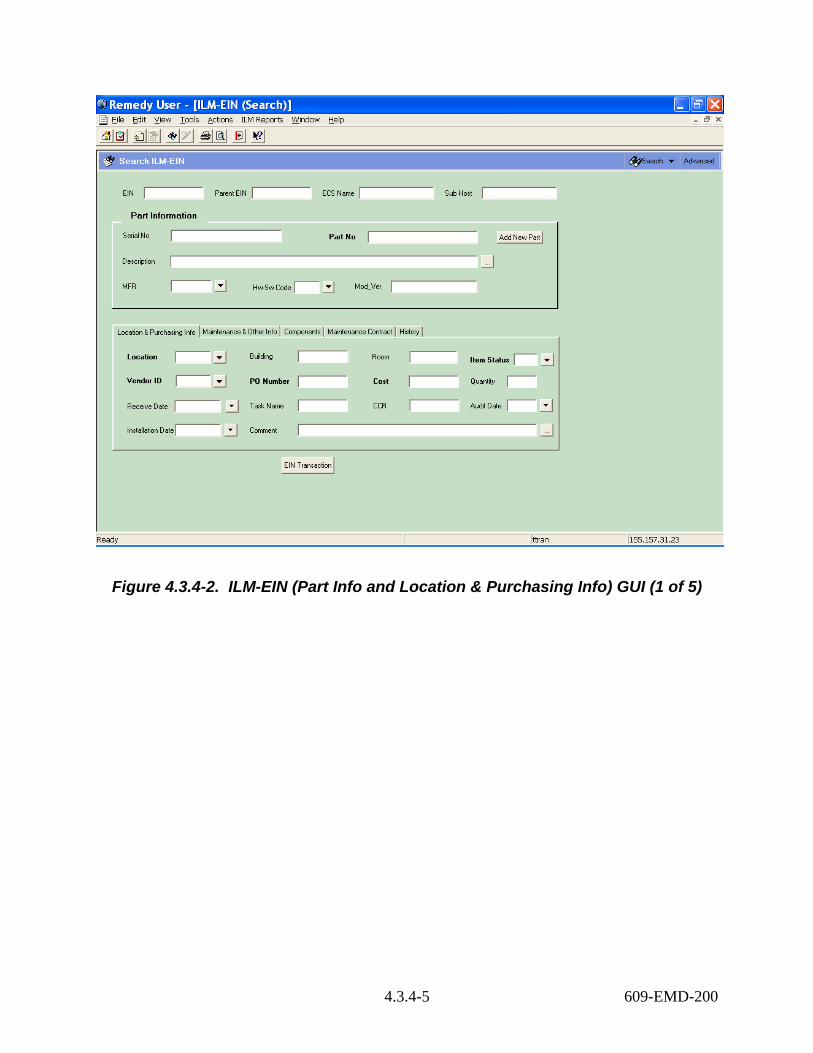
Figure 4.3.4-2. ILM-EIN (Part Info and Location & Purchasing Info) GUI (1 of 5)
4.3.4-5 609-EMD-200

Figure 4.3.4-3. ILM-EIN (Maintenance & Other Info.) GUI (2 of 5)
4.3.4-6 609-EMD-200

Figure 4.3.4-4. ILM-EIN (Components) GUI (3 of 5)
4.3.4-7 609-EMD-200

Figure 4.3.4-5. ILM-EIN (Maintenance Contract) GUI (4 of 5)
4.3.4-8 609-EMD-200

Figure 4.3.4-6. ILM-EIN (History) GUI (5 of 5)
Table 4.3.4-2 describes the fields on the ILM-EIN form.
4.3.4-9 609-EMD-200
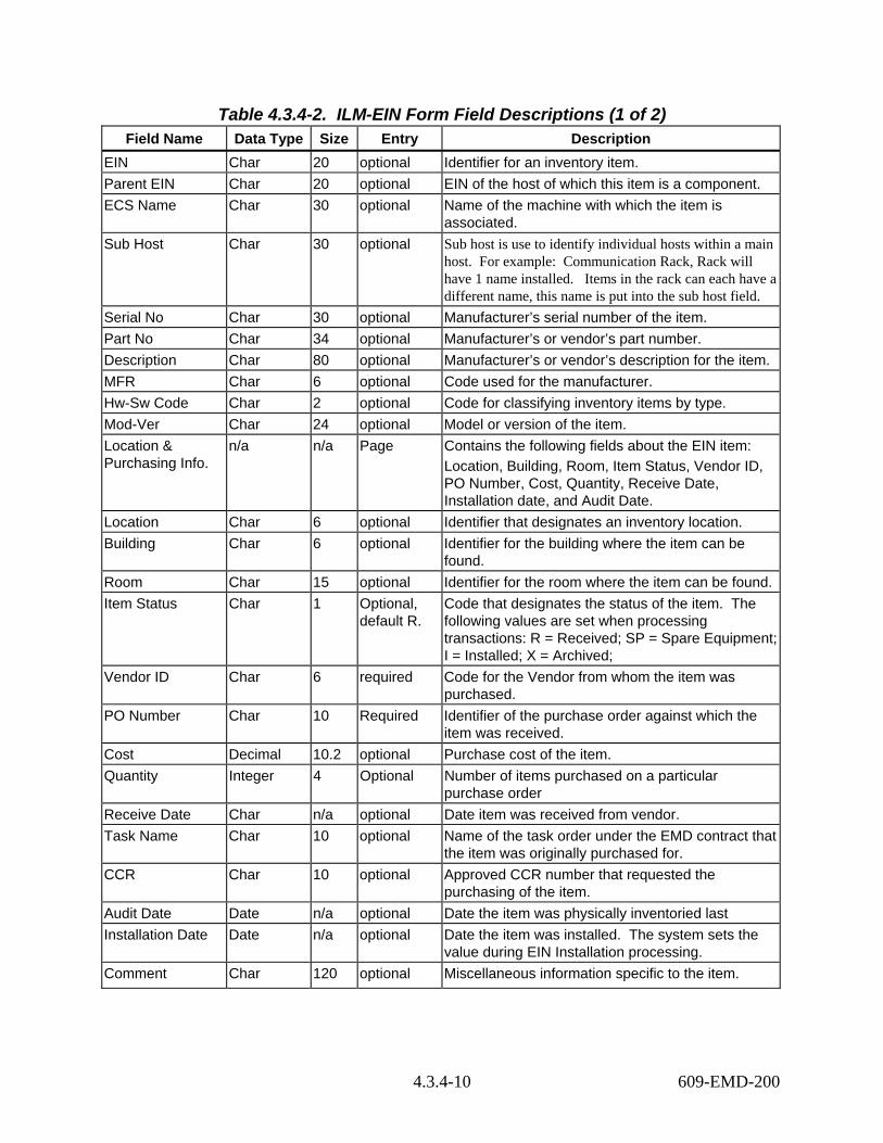
Table 4.3.4-2. ILM-EIN Form Field Descriptions (1 of 2) Field Name Data Type Size Entry Description
EIN Char 20 optional Identifier for an inventory item. Parent EIN Char 20 optional EIN of the host of which this item is a component. ECS Name Char 30 optional Name of the machine with which the item is
associated. Sub Host Char 30 optional Sub host is use to identify individual hosts within a main
host. For example: Communication Rack, Rack will have 1 name installed. Items in the rack can each have a different name, this name is put into the sub host field.
Serial No Char 30 optional Manufacturer’s serial number of the item. Part No Char 34 optional Manufacturer’s or vendor’s part number. Description Char 80 optional Manufacturer’s or vendor’s description for the item. MFR Char 6 optional Code used for the manufacturer. Hw-Sw Code Char 2 optional Code for classifying inventory items by type. Mod-Ver Char 24 optional Model or version of the item. Location & Purchasing Info.
n/a n/a Page Contains the following fields about the EIN item: Location, Building, Room, Item Status, Vendor ID, PO Number, Cost, Quantity, Receive Date, Installation date, and Audit Date.
Location Char 6 optional Identifier that designates an inventory location. Building Char 6 optional Identifier for the building where the item can be
found. Room Char 15 optional Identifier for the room where the item can be found.Item Status Char 1 Optional,
default R. Code that designates the status of the item. The following values are set when processing transactions: R = Received; SP = Spare Equipment; I = Installed; X = Archived;
Vendor ID Char 6 required Code for the Vendor from whom the item was purchased.
PO Number Char 10 Required Identifier of the purchase order against which the item was received.
Cost Decimal 10.2 optional Purchase cost of the item. Quantity Integer 4 Optional Number of items purchased on a particular
purchase order Receive Date Char n/a optional Date item was received from vendor. Task Name Char 10 optional Name of the task order under the EMD contract that
the item was originally purchased for. CCR Char 10 optional Approved CCR number that requested the
purchasing of the item. Audit Date Date n/a optional Date the item was physically inventoried last Installation Date Date n/a optional Date the item was installed. The system sets the
value during EIN Installation processing. Comment Char 120 optional Miscellaneous information specific to the item.
4.3.4-10 609-EMD-200

Table 4.3.4-2. ILM-EIN Form Field Descriptions (2 of 2) Field Name Data Type Size Entry Description
Maintenance & Other Info.
n/a n/a Page Contains the following fields about the EIN item: Maint Contract ID, Maint Exp Date, Maint Vendor, Warranty Exp Date, EMOSD ID, GFE Num, Comment, NASA Contract, Submitter, Create Date, and Last Modified By.
Maint Contract ID Char 10 optional Identifier for the Maintenance Contract under which the item is covered.
Maint Exp Date Date n/a optional Date the maintenance contract will expire. This field reflects the Expiration Date from the Maint Contract ID entered above.
Maint Vendor Char 6 optional Code for the vendor the maintenance contract were purchased from.
Warranty EXP Date
Date n/a optional Date that the warranty expires.
GFE NUM Char 8 optional Identifier assigned by the Government to an item of government furnished equipment.
NASA Contract Char 11 Optional, default NAS5-60000
Identifier designating the government contract used for this item. This information is automatically assigned and can not be changed.
Submitter Char 30 system-supplied
The user whom created the record.
Create Date Date n/a system-supplied
Date the record was created.
Last Modified By Char 30 system-supplied
The user last modified the record.
Modified Date Date/Time n/a System-supplied
The last date/time the record was modified.
Request ID Char 15 System-supplied
Provides record identifier.
Components n/a n/a Page Page for displaying the components of a parent EIN. It displays the Component EIN, ECS Name, Sub Host, Description, Serial No, Active Date, Inactive Date, and Room.
Maintenance Contract
n/a n/a Page Page displays attributes of the maintenance contract, such as the Contract ID, Start Date, Expiration Date, Type of support, PO number, maintenance vendor, and vendor ID.
History n/a n/a Page Contains a listing of EIN transaction history for the EIN. This table displays the following fields describing the transactions: Trans Type, Date-Time, Operator ID, From Parent EIN, From ECS Name, From Location, From Room, To Parent EIN, To ECS Name, To Location, and To Room.
4.3.4-11 609-EMD-200

The following buttons are unique to this form: • Add New Part – Activates the ILM-OEM Parts form. This allows the operator to add
new parts or to search for existing parts. • EIN Transaction – brings up the ILM-EIN Transaction form.
4.3.4.2.2 ILM-EIN Structure GUI The ILM-EIN Structure form (Figure 4.3.4-7) is designed to allow an Administrator to repair EIN structure records. Other ILM groups may view EIN Structure via the ILM-EIN form discussed in the previous section. To make changes to EIN Structures, always use the ILM-EIN Transaction form that is discussed in Section 4.3.4.2.3.
Figure 4.3.4-7. ILM-EIN Structure GUI
Table 4.3.4-3 contains descriptions of the ILM-EIN Structure form’s fields.
4.3.4-12 609-EMD-200
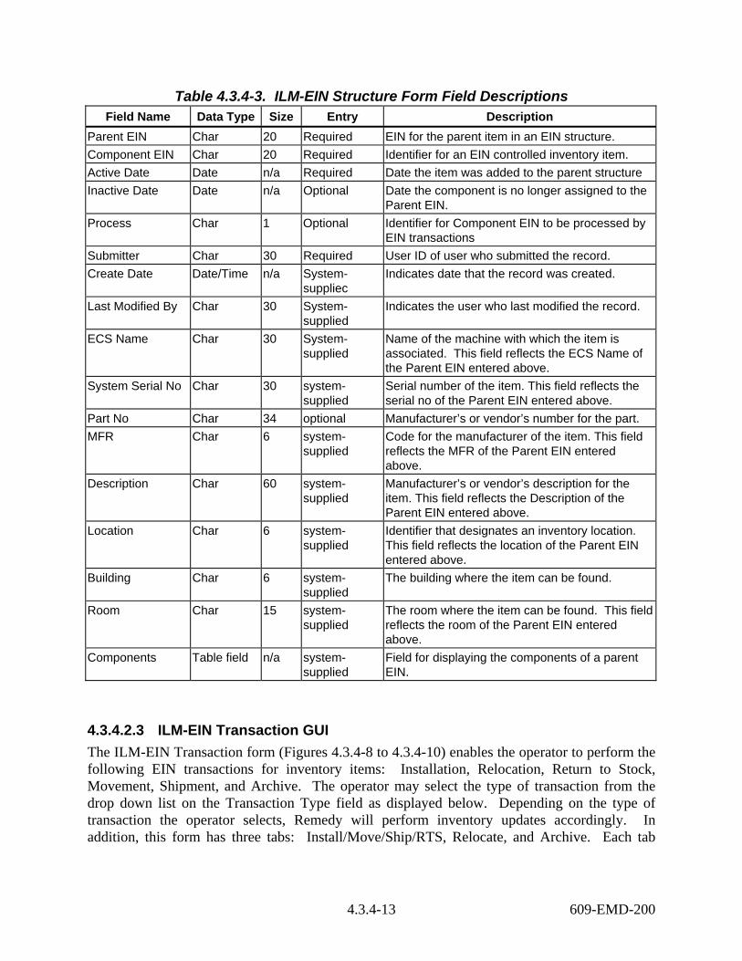
Table 4.3.4-3. ILM-EIN Structure Form Field Descriptions Field Name Data Type Size Entry Description
Parent EIN Char 20 Required EIN for the parent item in an EIN structure. Component EIN Char 20 Required Identifier for an EIN controlled inventory item. Active Date Date n/a Required Date the item was added to the parent structure Inactive Date Date n/a Optional Date the component is no longer assigned to the
Parent EIN. Process Char 1 Optional Identifier for Component EIN to be processed by
EIN transactions Submitter Char 30 Required User ID of user who submitted the record. Create Date Date/Time n/a System-
suppliec Indicates date that the record was created.
Last Modified By Char 30 System-supplied
Indicates the user who last modified the record.
ECS Name Char 30 System-supplied
Name of the machine with which the item is associated. This field reflects the ECS Name of the Parent EIN entered above.
System Serial No Char 30 system-supplied
Serial number of the item. This field reflects the serial no of the Parent EIN entered above.
Part No Char 34 optional Manufacturer’s or vendor’s number for the part. MFR Char 6 system-
supplied Code for the manufacturer of the item. This field reflects the MFR of the Parent EIN entered above.
Description Char 60 system-supplied
Manufacturer’s or vendor’s description for the item. This field reflects the Description of the Parent EIN entered above.
Location Char 6 system-supplied
Identifier that designates an inventory location. This field reflects the location of the Parent EIN entered above.
Building Char 6 system-supplied
The building where the item can be found.
Room Char 15 system-supplied
The room where the item can be found. This field reflects the room of the Parent EIN entered above.
Components Table field n/a system-supplied
Field for displaying the components of a parent EIN.
4.3.4.2.3 ILM-EIN Transaction GUI The ILM-EIN Transaction form (Figures 4.3.4-8 to 4.3.4-10) enables the operator to perform the following EIN transactions for inventory items: Installation, Relocation, Return to Stock, Movement, Shipment, and Archive. The operator may select the type of transaction from the drop down list on the Transaction Type field as displayed below. Depending on the type of transaction the operator selects, Remedy will perform inventory updates accordingly. In addition, this form has three tabs: Install/Move/Ship/RTS, Relocate, and Archive. Each tab
4.3.4-13 609-EMD-200

contains different information. For instance, Install/Move/Ship/RTS tab contains fields that are applicable to EIN Installation, EIN Movement, EIN Shipment, and Return To Stock. Relocate tab displays fields for EIN Relocation. Archive tab displays field for EIN Archive. The operator can specify components to be processed by pressing the “Select Components to Process” button. Remedy then transfers the operator to the ILM-Process Component form to complete the transaction. Figures 4.3.4.8 to 4.3.4-10 display fields for each tab and Table 4.3.4-4 provides the fields definitions for this form.
Figure 4.3.4-8. ILM-EIN Transaction (Install/Move/Ship/RTS) GUI (1 of 3)
4.3.4-14 609-EMD-200

Figure 4.3.4-9. ILM-EIN Transaction (Relocation) GUI (2 of 3)
Figure 4.3.4-10. ILM-EIN Transaction (Archive) GUI (3 of 3)
Table 4.3.4-4 provides the fields definitions for the ILM-EIN Transaction form.
4.3.4-15 609-EMD-200

Table 4.3.4-4. ILM-EIN Transaction Form Field Descriptions (1 of 2) Field Name Data Type Size Entry Description
Parent EIN Char 20 required EIN for the parent item in an EIN structure. Effective Date Date Optional The date the transaction is in effect. Transaction Type Char 15 Required Type of transaction performs on the Parent EIN
such as Installation, relocation, movement, shipment, and archive.
ECS Name Char 30 System-supplied
Name of the machine with which the item is associated. This field reflects the ECS Name of the Parent EIN entered above.
System Serial No Char 30 system-supplied
Serial number of the item. This field reflects the serial no of the Parent EIN entered above.
Part No Char 34 system-supplied
Manufacturer’s or vendor’s part number. This field reflects the Part No of the Parent EIN entered above.
Description Char 60 system-supplied
Manufacturer’s or vendor’s description for the item. This field reflects the Description of the Parent EIN entered above.
MFR Char 6 system-supplied
Code for the manufacturer of the item. This field reflects the MFR of the Parent EIN entered above.
Location Char 6 system-supplied
Identifier that designates an inventory location. This field reflects the location of the Parent EIN entered above.
Building Char 6 system-supplied
The building where the item can be found.
Room Char 15 system-supplied
The room where the item can be found. This field reflects the room of the Parent EIN entered above.
Install/Move/Ship/RTS
Page n/a n/a This page contains the following fields to perform the EIN Installation, Movement, Shipment, and Return to Stock: Return (P)arent-(C)omponent, Ship (P)arent-(C)omponent, New ECS Name, New Location, New Building, and New Room.
Return (P)arent-(C)omponent
Char 1 Optional, P or C
Identify whether the operator will return Parent and all of the components or return subset of components.
Ship (P)arent-(C)omponent
Char 1 Optional, P or C
Identify whether the operator will ship Parent and all of the components or ship subset of components.
New ECS Name Char 30 Optional New ECS Name for the Parent EIN. New Location Char 6 Optional New Location where the item will be at. New Building Char 6 Optional New Building where the item will be. New Room Char 15 Optional New room where the item will be located.
4.3.4-16 609-EMD-200

Table 4.3.4-4. ILM-EIN Transaction Form Field Descriptions (2 of 2) Field Name Data Type Size Entry Description
Relocate Page n/a n/a This page contains the New Parent EIN field for user to perform EIN relocation.
New Parent EIN Char 20 Optional New Parent EIN to which the item(s) will be associated with.
Archive Page n/a n/a This page contains the following fields to perform EIN archive: Archive (P)arent-(C)omponent and Type of Archive.
Archive (P)arent-(C)omponent
Char 1 Optional, P or C
Identify whether the operator will archive the Parent as well as all the active components or archive a subset of components.
Type of Archive Char 6 Optional, X,TV,G, RG
Define the type of archive the item(s). Return to Vendor – X,Trade in to vendor - TV Transferred to government - G Government Relieved Accountability - RG
♦ Pressing the Execute Transaction button will cause the processing of the transaction and the updating of the inventory items in accordance with the type of transaction the operator selected.
♦ Pressing the “Select Components To Process” button will bring up the ILM-Process Component form. This button is visible only when the transaction is associated with components.
4.3.4.2.3.1 ILM-Join-Process Component GUI The ILM-Join-Process Component form (Figure 4.3.4-11) displays all the active components for the Parent EIN entered in the ILM-EIN Transaction form and lets the operator specify component to undergo an EIN transaction. This form can be accessed through the “Select Components To Process” button on the bottom of the ILM-EIN Transaction form. However, this button is only visible when the transaction is being performed on components only. For example, the “Select Components To Process” button becomes visible when the user selects to return components (Return (P)arent-(C)omponent) to stock, or relocate components to a new EIN Structure, or archive selected components.
4.3.4-17 609-EMD-200
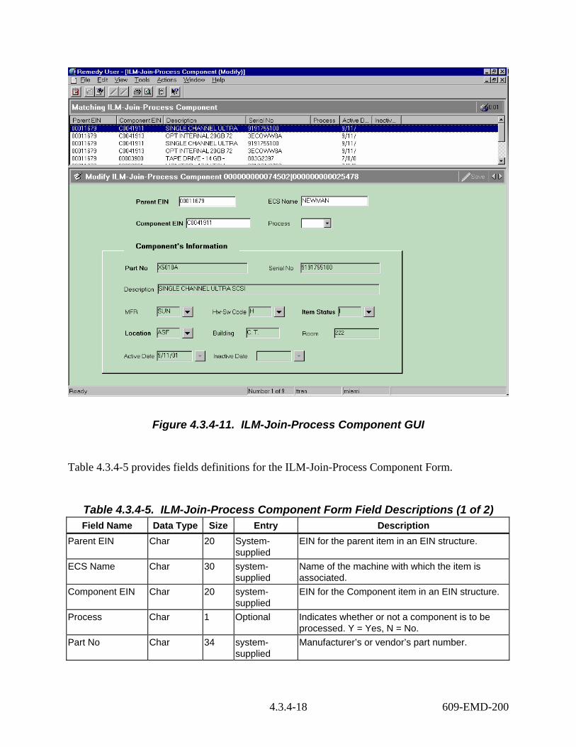
Figure 4.3.4-11. ILM-Join-Process Component GUI
Table 4.3.4-5 provides fields definitions for the ILM-Join-Process Component Form.
Table 4.3.4-5. ILM-Join-Process Component Form Field Descriptions (1 of 2) Field Name Data Type Size Entry Description
Parent EIN Char 20 System-supplied
EIN for the parent item in an EIN structure.
ECS Name Char 30 system-supplied
Name of the machine with which the item is associated.
Component EIN Char 20 system-supplied
EIN for the Component item in an EIN structure.
Process Char 1 Optional Indicates whether or not a component is to be processed. Y = Yes, N = No.
Part No Char 34 system-supplied
Manufacturer’s or vendor’s part number.
4.3.4-18 609-EMD-200

Table 4.3.4-5. ILM-Join-Process Component Form Field Descriptions (2 of 2) Field Name Data Type Size Entry Description
Serial No Char 30 system-supplied
Serial number of the item.
Description Char 60 system-supplied
Manufacturer’s or vendor’s description for the item.
MFR Char 6 system-supplied
Code for the manufacturer of the item.
Hw-Sw Code Char 2 system-supplied
Code for classifying items according to source of inventory. This code is provided automatically. Do not change it, manually.
Item Status Char 1 system-supplied
Code that designates the status of the item.
Location Char 6 system-supplied
Identifier that designates an inventory location.
Building Char 6 system-supplied
The build where the item can be found.
Room Char 15 system-supplied
The room where the item can be found.
Active Date Date n/a system-supplied
Date the item was added to the parent structure
Inactive Date Date n/a system-supplied
Date the component is no longer assigned to the EIN Structure.
4.3.4.2.3 ILM-Transaction Log ILM-Transaction Log form (Figure 4.3.4-12) is designed for viewing/browsing all the EIN transactions performed on property records. Remedy logs the type of transaction, date/time, operator initiating the transaction, ECS name, Parent EIN, and location changes. This form also shows property record changes due to maintenance actions performed on inventory items (refer to Section 4.3.4.3 for description of maintenance actions.).
4.3.4-19 609-EMD-200

Figure 4.3.4-12. ILM-Transaction Log GUI
Table 4.3.4-6 describes the fields on the ILM-Transaction Log form.
4.3.4-20 609-EMD-200
Table 4.3.4-6. ILM-Transaction Log Form Field Descriptions (1 of 2) Field Name Data Type Size Entry Description
Transaction No Numeric 10 system-supplied
A system generated number that uniquely identify the transaction.
Trans Type Char 5 system-supplied
The type of transaction operators perform on an inventory item, including: INS - Install, MVE – Move, REL - Relocate, ARC – Archive, MFS – Failed and Returned to Stock, MFV – Failed and returned to the vendor, MNS – New and came from stock, MNV – New and came from vendor, MRR – Relocate to a new Parent via the MWO, and MRS – Relocate to stock via the MWO.
Date-Time Date n/a system-supplied
Date and time the transaction occurred.
Operator ID Char 10 system-supplied
The operator id who performed the transaction.
EIN Char 20 system-supplied
The EIN number that the transaction performed on.
ECS Name Char 30 system-supplied
Name of the machine with which the item is associated.
Serial No Char 30 system-supplied
Serial number of the item
Part No Char 30 system-supplied
Manufacture's or vendor's part number.
Description Char 60 system-supplied
Manufacturer's or vendor's description of the item.
MFR Char 6 system-supplied
Code for the manufacturer of the item
Item Status Char 1 Optional, default R.
Code that designates the status of the item. The following values are set when processing transactions: R = Received; SP = Spare Equipment; I = Installed; X = Archived;
Location Char 6 system-supplied
Identifier that designates an inventory location. This field reflects the location of the Parent EIN entered above.
Building Char 6 system-supplied
The building where the item can be found.
Room Char 15 system-supplied
The room where the item can be found. This field reflects the room of the Parent EIN entered above.
From Parent EIN Char 20 system-supplied
The parent EIN where the EIN originated from.
To Parent EIN Char 20 system-supplied
The new parent EIN where the EIN is locating.
4.3.4-21 609-EMD-200
Table 4.3.4-6. ILM-Transactions Log Form Field Descriptions (2 of 2) Field Name Data Type Size Entry Description
From ECS Name Char 30 system-supplied
Name of the machine with which the item is associated
To ECS Name Char 30 system-supplied
Name of the machine with which the item is associated
From Location Char 6 system-supplied
The original location where the EIN was.
To Location Char 6 system-supplied
The new location where the EIN can be found.
From Building Char 6 system-supplied
The original building where the EIN was located.
To Building Char 6 system-supplied
The new building where the EIN is located.
From Room Char 15 system-supplied
The Original room where the EIN located.
To Room Char 15 system-supplied
The new room where the EIN can be found.
4.3.4.2.6 ILM-OEM Parts GUI Operators use the ILM-OEM Parts form (Figure 4.3.4-13) to maintain standardized information about manufacturer’s parts. Parts information must be recorded in the ILM-OEM Parts form before they can be added to an inventory item’s record.
4.3.4-22 609-EMD-200

Figure 4.3.4-13. ILM-OEM Parts GUI
Table 4.3.4-7 provides the definitions for fields on the ILM-OEM Parts form.
Table 4.3.4-7. ILM-OEM Parts Form Field Descriptions Field Name Data Type Size Entry Description
Part No Char 34 required Manufacturer’s or vendor’s part number for an item.
MFR Char 6 required Code for the manufacturer of the item. Hw-Sw Code Char 2 optional Code for classifying items according to source of
maintenance costs. Mod-Ver Char 24 optional Model or version of the item. Description Char 60 required Manufacturer’s or vendor’s description of the
item. Create Date Date n/a system-
supplied Date the record was created.
Submitter Char 30 system-supplied
The user who created the record.
Last Modified By Char 30 system-supplied
User ID of the last person that modified the record.
4.3.4-23 609-EMD-200

4.3.4.2.7 ILM-Vendor-MFR GUI The ILM-Vendor-MFR form (Figure 4.3.4-14) enables operators to define valid vendor codes for use with EIN records. The operator enters the data or modifies the data in the fields for this form as required.
Figure 4.3.4-14. ILM-Vendor-MFR GUI
Table 4.3.4-8 describes the fields on the ILM-Vendor-MFR form.
4.3.4-24 609-EMD-200

Table 4.3.4-8. ILM-Vendor-MFR Form Field Descriptions Field Name Data Type Size Entry Description
Vendor ID Char 6 required Code for a vendor from whom items are purchased.
Vendor Name Char 30 optional Full name of a vendor from who items are purchased.
Submitter Char 30 system-supplied
The user whom created the record.
Create Date Date n/a system-supplied
Date the record was created.
Last Modified By Char 30 system-supplied
The user that last modified the record.
4.3.4.2.8 ILM-HwSw Codes GUI Operators use this form (Figure 4.3.4-15) to maintain a standard set of codes for distinguishing items according to source of maintenance costs. These codes are associated with EIN items and are essential for grouping inventory items for reporting and browsing.
Figure 4.3.4-15. ILM-HwSw Codes GUI
Table 4.3.4-9 describes the fields on the ILM-HwSw Codes form.
4.3.4-25 609-EMD-200

Table 4.3.4-9. ILM-HwSw Codes Form Field Descriptions Field Name Data Type Size Entry Description
Hw/Sw Code Char 2 required Code for classifying items according to source of maintenance costs.
Description Char 30 required Description for the Hardware/Software code.
4.3.4.2.9 ILM-Status Codes GUI The ILM-Status Codes form (Figure 4.3.4-16) maintains a set of standardized codes for identifying valid inventory item states in the inventory and logistics life cycle.
Figure 4.3.4-16. ILM-Status Codes GUI
Table 4.3.4-10 describes the fields on the ILM-Status Codes form.
Table 4.3.4-10. ILM-Status Codes Form Field Descriptions Field Name Data Type Size Entry Description
Item Status Char 6 required Code for an inventory status for an item. Description Char 30 required Description for the code.
4.3.4-26 609-EMD-200
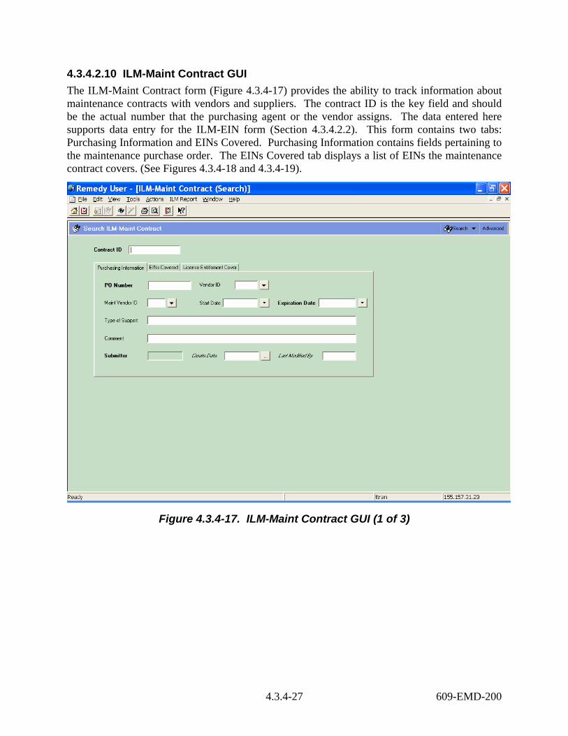
4.3.4.2.10 ILM-Maint Contract GUI The ILM-Maint Contract form (Figure 4.3.4-17) provides the ability to track information about maintenance contracts with vendors and suppliers. The contract ID is the key field and should be the actual number that the purchasing agent or the vendor assigns. The data entered here supports data entry for the ILM-EIN form (Section 4.3.4.2.2). This form contains two tabs: Purchasing Information and EINs Covered. Purchasing Information contains fields pertaining to the maintenance purchase order. The EINs Covered tab displays a list of EINs the maintenance contract covers. (See Figures 4.3.4-18 and 4.3.4-19).
Figure 4.3.4-17. ILM-Maint Contract GUI (1 of 3)
4.3.4-27 609-EMD-200

Figure 4.3.4-18. ILM-Maint Contract GUI (2 of 3)
4.3.4-28 609-EMD-200

Figure 4.3.4-19. ILM-Maint Contract GUI (3 of 3)
Table 4.3.4-11 provides definitions for fields on the ILM-Maint Contract form.
Table 4.3.4-11. ILM-Maint Contract Form Field Descriptions (1 of 2) Field Name Data Type Size Entry Description
Contract ID Char 10 Required Identifier for the maintenance contract as assigned by purchasing or provided by the vendor
PO Number Char 10 Required Purchase order number of the purchase order that procured the maintenance coverage.
Vendor ID Char 6 Optional Code for the vendor with whom the contract is placed.
Maint Vendor ID Char 6 Optional Code for the vendor whom will provide the services
Start Date Date n/a Optional Date the contract is to become effective Expiration Date Date n/a Required Date the contract will expire
4.3.4-29 609-EMD-200

Table 4.3.4-11. ILM-Maint Contract Form Field Descriptions (2 of 2) Field Name Data Type Size Entry Description
Type of Support Char 60 Optional Type of support procured. Comment Char 60 Optional Miscellaneous information specific to the
maintenance contract Submitter Char 30 system-
supplied The user whom created the record.
Create Date Date system-supplied
Date the record was created.
Last Modified By Char 30 system-supplied
The last date the record was modified.
EINs Covered Page n/a system-supplied
Page for displaying the EINs covered under the maintenance contract
License Entitlement Cover
Page n/a System-supplied
Page for displaying the license entitlements covered under the maintenance contract.
4.3.4.2.11 ILM-Sites GUI This form (Figure 4.3.4-20) allows operators to maintain a set of valid standard codes and descriptions for identifying ECS sites. Each code represents one site.
Figure 4.3.4-20. ILM-Sites GUI
4.3.4-30 609-EMD-200

Table 4.3.4-12 describes the fields on the ILM-Sites form.
Table 4.3.4-12. ILM-Sites Form Field Descriptions Field Name Data Type Size Entry Description
Site Char 6 Required Code for an ECS site. Description Char 40 optional Description of the Site.
4.3.4.2.12 ILM-Inventory Location GUI The form shown in Figure 4.3.4-21 is used to maintain information about ECS inventory locations. This standardized information is available to other screens and reports, which can access it by reference to a location.
Note: An important distinction is made in Remedy between an ECS site and an inventory location. Sites are officially designated by NASA and generally include the SMC, DAACs, and other official support installations. ECS Property Administrators designate inventory locations for purposes of property management. They are typically facilities or locales where inventory items are stored or installed and there can be more than one inventory location at a site. Inventory locations are sometimes assigned the same names and codes as a site, but Remedy treats the two as different entities.
Figure 4.3.4-21. ILM-Inventory Location GUI
4.3.4-31 609-EMD-200
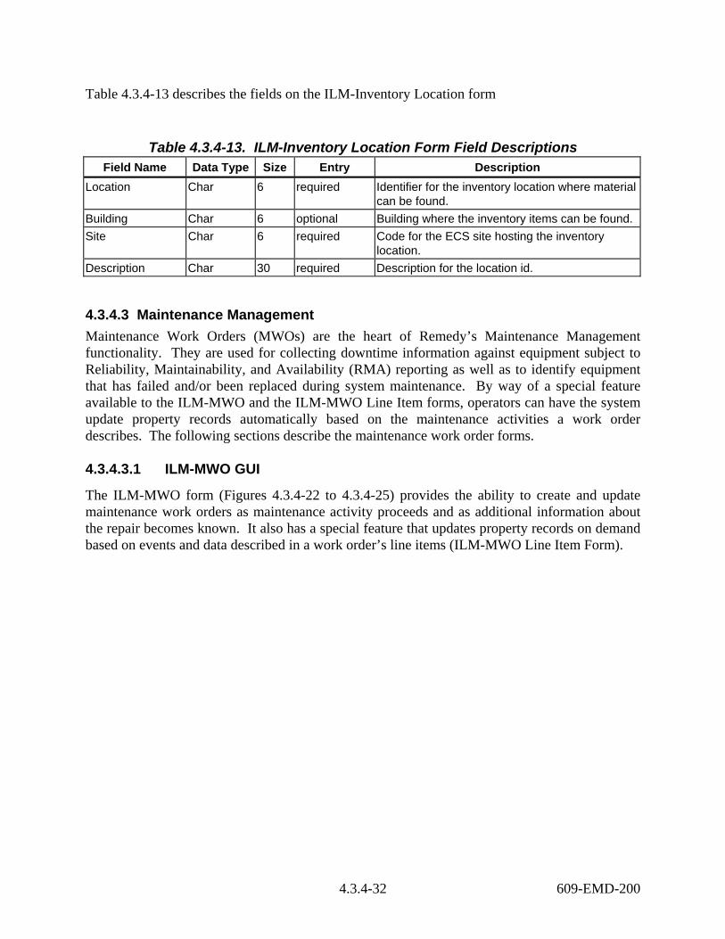
Table 4.3.4-13 describes the fields on the ILM-Inventory Location form
Table 4.3.4-13. ILM-Inventory Location Form Field Descriptions Field Name Data Type Size Entry Description
Location Char 6 required Identifier for the inventory location where material can be found.
Building Char 6 optional Building where the inventory items can be found. Site Char 6 required Code for the ECS site hosting the inventory
location. Description Char 30 required Description for the location id.
4.3.4.3 Maintenance Management Maintenance Work Orders (MWOs) are the heart of Remedy’s Maintenance Management functionality. They are used for collecting downtime information against equipment subject to Reliability, Maintainability, and Availability (RMA) reporting as well as to identify equipment that has failed and/or been replaced during system maintenance. By way of a special feature available to the ILM-MWO and the ILM-MWO Line Item forms, operators can have the system update property records automatically based on the maintenance activities a work order describes. The following sections describe the maintenance work order forms.
4.3.4.3.1 ILM-MWO GUI
The ILM-MWO form (Figures 4.3.4-22 to 4.3.4-25) provides the ability to create and update maintenance work orders as maintenance activity proceeds and as additional information about the repair becomes known. It also has a special feature that updates property records on demand based on events and data described in a work order’s line items (ILM-MWO Line Item Form).
4.3.4-32 609-EMD-200
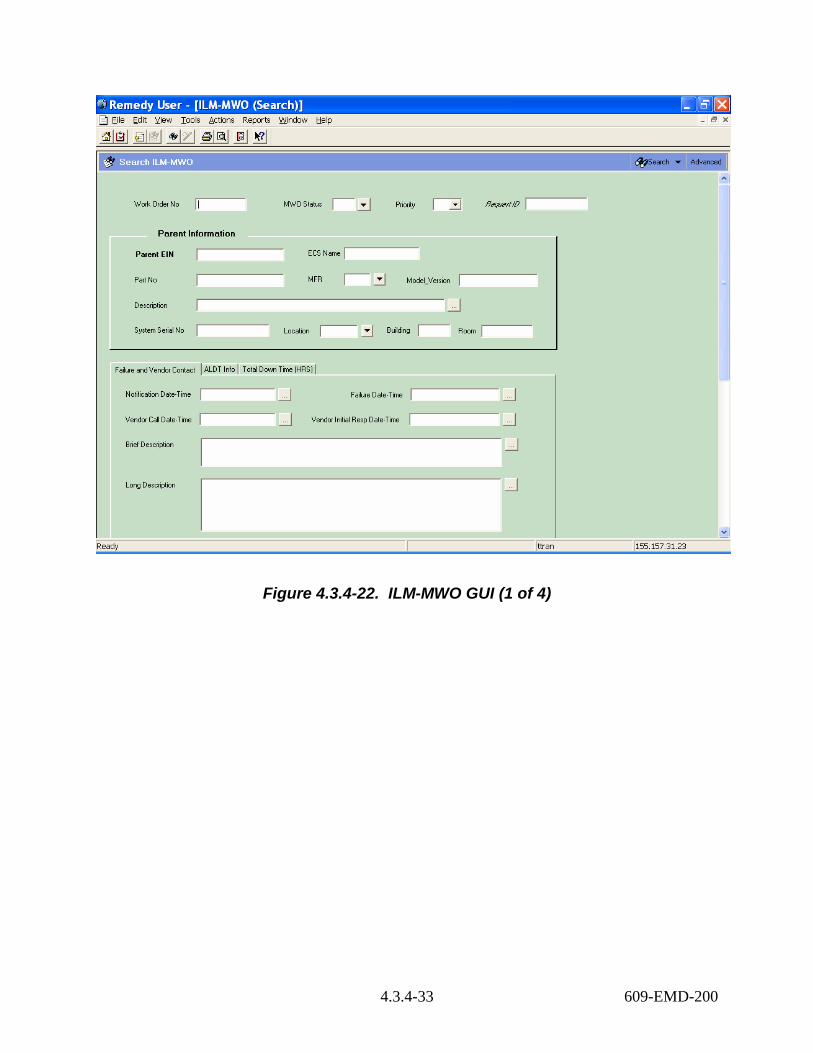
Figure 4.3.4-22. ILM-MWO GUI (1 of 4)
4.3.4-33 609-EMD-200
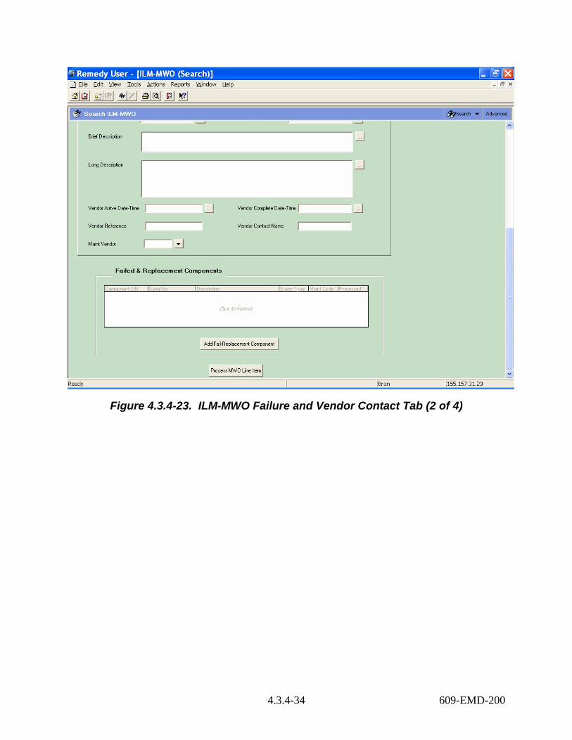
Figure 4.3.4-23. ILM-MWO Failure and Vendor Contact Tab (2 of 4)
4.3.4-34 609-EMD-200

Figure 4.3.4-24. ILM-MWO ALDT Info Tab (3 of 4)
Figure 4.3.4-25. ILM-MWO Total Down Time Tab (4 of 4)
4.3.4-35 609-EMD-200

Table 4.3.4-14 describes the fields on the ILM-MWO Form.
Table 4.3.4-14. ILM-MWO Form Field Descriptions (1 of 3) Field Name Data Type Size Entry Description
Work Order No Char 10 system-supplied
Identifier for the work order.
MWO Status Char 1 optional; O, A, F, or R
Code for the status of the work order. O = Open; A = Audit; F=Finish; R = Retired.
Priority Char 1 optional Code for the priority assigned to the work. Request ID Char 15 System-
supplied Provides and displays the record identifier.
Parent EIN Char 20 optional EIN for the parent item in an EIN structure. ECS Name Char 30 system-
supplied from EIN record
Name of the machine with which the item is associated.
Part No Char 34 system-supplied from EIN record
Manufacturer’s part number for the item entered as Parent EIN.
MFR Char 6 optional Code for the manufacturer of the item. Model_Version Char 24 optional Manufacturer model number or version number
for the item. Description Char 60 system-
supplied from EIN record
Manufacturer’s description for the item entered as Parent EIN.
System Serial Number
Char 30 system-supplied
Serial number of the item entered as Parent EIN.
Location Char 8 system-supplied from EIN record
Designator for the location where the item entered as Parent EIN is situated.
Building Char 6 optional Building where the item will be found. Room Char 6 system-
supplied from EIN record
Room in which the item entered as Parent EIN is situated.
Notification Date-Time
Date-Time n/a optional The date and time problem was reported. This field is initialized with the current date and time but can be modified.
Failure Date-Time Date-Time n/a optional Date and time that the failure occurred. Vendor Call Date-Time
Date-Time n/a optional The date and time the maintenance vendor was called.
Vendor Initial Resp Date-Time
Date-Time n/a Optional Indicate the vendor initial response date and time to the service call.
Brief Description Char 140 Optional A brief description of the problem and resolution Long Description Char 1024 optional A long description of the problem and resolution
relevant to the maintenance event
4.3.4-36 609-EMD-200

Table 4.3.4-14. ILM-MWO Form Field Descriptions (2 of 3) Field Name Data Type Size Entry Description
Vendor Arrive Date-Time
Date-Time n/a optional The date and time the maintenance vendor actually arrived to perform the repairs.
Vendor Complete Date-Time
Date-Time n/a optional Date and time the repair was completed.
Vendor Reference Char 20 optional Operator has option to enter any information in reference to the vendor.
Vendor Contact Name
Char 30 optional Vendor point of contact.
Maint Vendor Char 6 optional Code for the vendor that provides maintenance support for this item.
ALDT Start Date-Time
Date-Time n/a optional The date and time a delay in repairing the system began.
ALDT End Date-Time
Date-Time n/a optional The date and time a delay in repairing the system ended.
ALDT Reason Char 60 optional A code for the reason a delay was encountered. ALDT2 Start Date-Time
Date-Time n/a optional The second delay date and time for when the vendor's work was suspended and resumed (including travel time, admin delays, and logistics delays).
ALDT2 End Date-Time
Date-Time n/a optional The second ending date and time for the delay.
ALDT2 Reason Char 60 optional The reason for the second delay. Start Restore Date-Time
Date-Time n/a optional The date and time when start restoring the failed system.
End Restore Date-Time
Date-Time n/a optional The date and time end restoring the system.
Total ALDT Real 5.2 optional Total Administrative logistic delay time (ALDT) Specified in hours.
Time To Repair Real 5.2 optional Time required to effect the repair. Specified in hours.
Switchover Time Real 5.2 optional Time required for system switch-over. Specified in hours.
Total Chargeable Down Time
Real 5.2 optional Time to be charged for downtime. Specified in hours.
Submitter Char 30 system-supplied
The user whom created the record.
Create Date Date n/a system-supplied
Date the record was created.
Last Modified By Char 30 system-supplied
The last date the record was modified.
4.3.4-37 609-EMD-200

Table 4.3.4-14. ILM-MWO Form Field Descriptions (3 of 3) Field Name Data Type Size Entry Description
Modified Date Date n/a system-supplied
The last date the record was modified.
Failed & Replacement Components
Table field n/a System-supplied
Field for displaying the failed and replacement components.
The following buttons/functions are unique to the ILM-MWO form:
• Add Fail/Replacement Component - provides access to the ILM-MWO Line Item Form (Figure 4.3.4-27) for adding or accessing data about components involved in individual maintenance actions.
• Process MWO Line Item - The Process MWO Line Item button provides a convenient, reliable, and efficient means for updating ILM property records based on information contained in ILM-MWO line item form. New EIN records are created as necessary, as are corresponding Part No and EIN structure records. Processing adds new items to the ECS inventory, archives those that have failed or been returned to the vendor, and re-assigns any that have been relocated or returned to stock. Additionally, items returned to a vendor are rendered obsolete with respect to their parent EINs and, of those that had failed, costs are transferred to their replacements. If Remedy is to update property records based on ILM-MWO line item data, line item records must specify values for Event Type and Maint Code. They determine the type of property record changes to be made. (See Table 4.3.4-15) Additionally, operators must supply a value for New Parent EIN if an item is designated for relocation. Other line item fields, such as Component EIN, Change Date, Replacement’s EIN, New Location, and New Room, have special significance as well in that they influence which database records actually change.
4.3.4.3.2 ILM-MWO Line Item GUI The ILM-MWO Line Item form (Figures 4.3.4-26 – 4.3.4-27) provides the ability for the Local Maintenance Coordinator to identify equipment that has failed and/or been replaced during system maintenance. In general, a line item would be created for each EIN component that has failed, been replaced, or been added new. Line items can be created even if an EIN record does not exist for the component, and operators can record observed details about a repair item even if the details conflict with what is currently contained in the EIN record for the item. This form has two sections the “Database Values” and the “Observed Values”. The “Database Values” displays the database value of the component EIN record if the Component EIN exists in the database. Operator may not update the fields listed in the “Database Values” section. However, the operator may update the Component EIN record in the “Observed Values” section to reflect the actual data of the Component EIN.
4.3.4-38 609-EMD-200
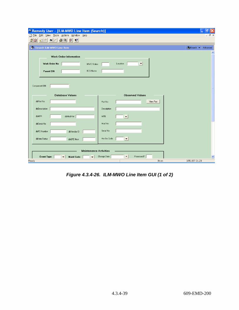
Figure 4.3.4-26. ILM-MWO Line Item GUI (1 of 2)
4.3.4-39 609-EMD-200

Figure 4.3.4-27. ILM-MWO Line Item GUI (2 of 2)
Table 4.3.4-15 describes the fields on the ILM-MWO Line Item form.
Table 4.3.4-15. ILM-MWO Line Item Form Field Descriptions (1 of 3) Field Name Data Type Size Entry Description
Work Order No Char 10 system-supplied
Identifier for the work order.
MWO Status Char 1 system-supplied
Code for the status of the work order. O = Open; A = Audit; F=Finish; R = Retired.
Location Char 6 system-supplied
Location of the Parent EIN.
Parent EIN Char 20 system-supplied
EIN for the parent item in an EIN structure.
ECS Name Char 30 System-supplied
Name of the machine with which the item is associated.
4.3.4-40 609-EMD-200

Table 4.3.4-15. ILM-MWO Line Item Form Field Descriptions (2 of 3) Field Name Data Type Size Entry Description
Component EIN Char 20 optional Identifier for an item that is a child (component) of a parent EIN and the target of the maintenance event. If the field is left null or blank, the system will create an inventory number with a C-prefix for it automatically when the line item is processed.
Database Values Section fields
n/a n/a system-supplied
If the entered Component EIN record exists in the ILM-EIN form, the system will populate the fields in this section with the data derived from the ILM-EIN form record.
Observed Values Section fields
n/a n/a n/a User may enter information that describes the Component EIN in this section. If the Component EIN does not exist in the database, the component EIN will be added to the database using the information provided in the fields in the Observed Values section.
Part No Char 34 optional Manufacturer’s or vendor’s part number for the item.
Description Char 60 optional Manufacturer’s or vendor’s description of the item. The operator may zoom to the OEM Parts table to choose a description, if it had been entered there previously (see the OEM Parts section).
MFR Char 6 optional Code used for the manufacturer of the item. The operator may zoom to the Vendor table to choose a code, if it had been entered there previously (see the Vendor Master section).
Mod-Ver Char 24 optional Model or Version of the item. Serial No Char 30 optional Serial number of the item. Hw-Sw Code Char 2 Optional Code for classifying items according to source of
inventory Event Type Char 1 required Code identifying a type of maintenance event
(N=new item installed; F=failed item replaced; R=serviceable item replaced).
Maint Code Char 1 required Code designating the item's disposition. Property records are updated differently depending on the value entered. (R = Relocate, S = Stock, V = Vendor).
Change Date Date required Effective date of the configuration change. Processed? Char 1 system
supplied Flag signifying whether or not the line item has been processed by the Work Order's .P(rocess_Changes) bottom-line command. The command updates the Component EIN's property records.
Comment Char 60 Optional Miscellaneous information specific to the item
4.3.4-41 609-EMD-200

Table 4.3.4-15. ILM-MWO Line Item Form Field Descriptions (3 of 3) Field Name Data Type Size Entry Description
Replacement’s EIN
Char 20 Optional Identifier of the new item being used as a replacement. This field is used only for items that have failed or that are being replaced (i.e., Event Type="F", or Event Type="R").
New Parent EIN Char 20 Optional EIN of the item to which the Component EIN is to be re-assigned. This field is applicable only to components that have failed or are being replaced (Event Type="F" or "R"), and are being relocated (Maint Code="R"). The value must be supplied or the item will not get processed.
New Location Char 6 optional Code for the new inventory location to which the item is to be assigned. This field is used for items that have failed or are being replaced (i.e., Event Type="R") and are being returned to stock.
New Building Char 6 optional Building where the item is to be installed. New Room Char 15 optional Room where the item is to be installed. Submitter Char 30 system-
supplied The user whom created the record.
Create Date Date system-supplied
Date the record was created.
Last Modified By Char 30 system-supplied
The last date the record was modified.
The following buttons are unique to this form:
• View Part – displays the record of the Part No. if it exists in the database.
• Add Another LI to MWO – brings up the MWO Line Item form to facilitate another line item record entry.
Table 4.3.4-16 lists the appropriate combinations of event types and maintenance codes and their effects on property records when processed.
4.3.4-42 609-EMD-200

Table 4.3.4-16. Effects on Property Records by MWO Line Item Processing (1 of 4)
Event Type
Maint Code Property Record Updates
F (Failed)
S (Stock)
Situation: an item has failed and has been returned to stock. EIN records: • Creates a record if one doesn’t exist for the specified component EIN • For the specified component EIN:
• Clears its Parent EIN • Clears its installation date • Sets Item status to “F” • Sets audit date to the Change Date • Sets ECS name to “IN STOCK” • Sets location, building, and room to new values.
OEM part records: • Creates an OEM Part record if “observed values” for Part No, MFR,
and Description are specified and the part record doesn’t already exist EIN structure records: • Obsoletes the specified component EIN in EIN Structures where it is
active. The structure is rendered inactive as of the specified Change Date
Inventory transaction records: • Creates an entry for event of type “MFS” for the specified component
F (Failed)
V (Vendor)
Situation: an item has failed and has been returned to the vendor. EIN records: • If the Component EIN field is blank, the system will not process the
record and sets the Process field to “X.” • Creates a record if one doesn’t exist for the specified component EIN • For the specified component EIN:
• Clears its Parent EIN • Clears its installation date • Sets item status to “X” • Sets audit date to the Change Date • Sets ECS name to “ARCHIVE” • Sets location to “EDFARC” and clears the building and room
values. OEM part records: • Creates an OEM Part record if “observed values” for Part No, MFR,
and Description are specified and the part record doesn’t already exist EIN structure records: • Obsoletes the specified component EIN in EIN Structures where it is
active. The structure is rendered inactive as of the specified Change Date
Inventory transaction records: • Creates an entry for event of type “MFV” for the specified component
4.3.4-43 609-EMD-200
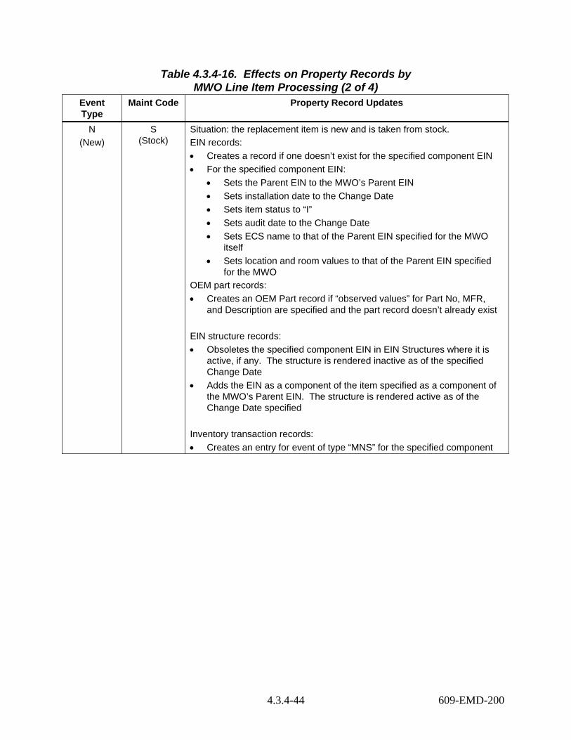
Table 4.3.4-16. Effects on Property Records by MWO Line Item Processing (2 of 4)
Event Type
Maint Code Property Record Updates
N (New)
S (Stock)
Situation: the replacement item is new and is taken from stock. EIN records: • Creates a record if one doesn’t exist for the specified component EIN • For the specified component EIN:
• Sets the Parent EIN to the MWO’s Parent EIN • Sets installation date to the Change Date • Sets item status to “I” • Sets audit date to the Change Date • Sets ECS name to that of the Parent EIN specified for the MWO
itself • Sets location and room values to that of the Parent EIN specified
for the MWO OEM part records: • Creates an OEM Part record if “observed values” for Part No, MFR,
and Description are specified and the part record doesn’t already exist EIN structure records: • Obsoletes the specified component EIN in EIN Structures where it is
active, if any. The structure is rendered inactive as of the specified Change Date
• Adds the EIN as a component of the item specified as a component of the MWO’s Parent EIN. The structure is rendered active as of the Change Date specified
Inventory transaction records: • Creates an entry for event of type “MNS” for the specified component
4.3.4-44 609-EMD-200

Table 4.3.4-16. Effects on Property Records by MWO Line Item Processing (3 of 4)
Event Type
Maint Code Property Record Updates
N (New)
V (Vendor)
Situation: the replacement item is new and came from the vendor. EIN records: • Creates a record if one doesn’t exist for the specified component EIN • For the specified component EIN:
• Sets the Parent EIN to the MWO’s Parent EIN • Sets installation date to the Change Date • Sets receive date to the Change Date • Sets item status to “I” • Sets audit date to the Change Date • Sets ECS name to that of the Parent EIN specified for the MWO
itself • Sets location, building, and room values to that of the Parent EIN
specified for the MWO itself • If the component is replacing an EIN specified in a separate line
item as a failed item being returned to the vendor and copies the item cost from the EIN record for the failed item to the EIN record for the new item
• For a failed item being replaced by the specified component EIN: • Sets cost to 0
OEM part records: • Creates an OEM Part record if “observed values” for Part No, MFR,
and Description are specified and the part record doesn’t already exist EIN structure records: • Obsoletes the specified component EIN in EIN Structures where it is
active, if any. The structure is rendered inactive as of the specified Change Date
• Adds the EIN as a component of the item specified as a component of the MWO’s Parent EIN. The structure is rendered active as of the Change Date specified
Inventory transaction records: • Creates an entry for event of type “MNV” for the specified component
4.3.4-45 609-EMD-200

Table 4.3.4-16. Effects on Property Records by MWO Line Item Processing (4 of 4)
Event Type
Maint Code Property Record Updates
R (Replaced)
R (Relocate)
Situation: an item is being relocated to a new machine. EIN records: • Creates a record if one doesn’t exist for the specified component EIN • For the specified component EIN:
• Sets the Parent EIN to the New Parent EIN • Sets the Installation Date to Change Date • Sets item status to “I” • Sets audit date to the Change Date • Sets ECS name to the name of the new parent EIN • Sets location, building, and room to that of the new parent EIN
OEM part records: • Creates an OEM Part record if “observed values” for Part No, MFR,
and Description are specified and the part record doesn’t already exist EIN structure records: • Obsoletes the specified component EIN in EIN Structures where it is
active. The structure is rendered inactive as of the specified Change Date
• Adds the EIN as a component of the item specified as New Parent EIN. The structure is rendered active as of the specified Change Date
Inventory transaction records: • Creates an entry for event of type “MRR” for the specified component
R (Replaced)
S (Stock)
Situation: an item is being returned to stock. EIN records: • Creates a record if one doesn’t exist for the specified component EIN • For the specified component EIN:
• Sets the Parent EIN to blank • Clears its installation date • Sets item status to “R” • Sets audit date to the Change Date • Sets ECS name to “IN STOCK” • Sets location, building, and room to new values, if specified
OEM part records: • Creates an OEM Part record if “observed values” for Part No, MFR,
and Description are specified and the part record doesn’t already exist EIN structure records: • Obsoletes the specified component EIN in EIN Structure where it is
active. The structure is rendered inactive as of the specified Change Date
• Inventory transaction records: • Creates an entry for event of type “MRS” for the specified component
4.3.4-46 609-EMD-200

4.3.4.4 License Management Many software products used in EMD are licensed; that is, subject to conditions of limiting how many users can run the product and where. Licenses take numerous forms. Nodelock licenses let users run the product, but only on a designated machine; counted nodelock licenses limit the number of users that can run the product on that machine. Floating licenses allow users to run a product from any machine in a network. They may limit the number of users that can run the product concurrently, the number of servers that can be used concurrently, the number of sites that can use the product, or any combination of the above. Licenses can apply to a named product, one or more of its features, one or more of its versions, and/or one or more types of platforms. Some vendors enforce these provisions through use of license keys, but ECS is accountable for adhering to licensing provisions whether vendors use keys or not.
The life cycle for licensed COTS software encompasses developmental and systems engineering, purchasing, receiving, stocking, distribution, installation, use, and recovery. Licenses associated with COTS products are obtained and allocated; they also expire. Licenses do not always change when the licensed product does.
When purchasing a product or obtaining an upgrade, engineering determines what licensing provisions are required. Depending on the product, license entitlements may appear as separate line items on purchase orders, but often not. (For example, purchased licensing provisions may be provided with the product; that is, not purchased separately.) License certificates (rights to certify) typically accompany software when it arrives and, in the case of operating system software, accompanies the computers themselves. These certificates describe the licensing provisions that were purchased and may carry an associated cost. Sometimes, the certificates include a license key, but usually they represent the right to obtain keys.
Multiple licenses are sometimes obtained from the product vendor under the provisions of a single license certificate. Each license would account for part of the rights-to-use under the certificate. Conversely, individual licenses can consume rights-to-use from more than one certificate. Each unique license key implies a unique license, but not every license has a key.
Licenses are allocated to the sites and host machines where their keys are installed, and keyless licenses are allocated to where their software products are installed. This is not so much for property accounting (i.e., cost accounting), but to verify adherence to purchased licensing provisions and to identify where licenses are used in case rights-to-use must transfer elsewhere. A single license can be allocated to multiple sites and machines, although it’s unclear at present whether a machine’s current location determines the license’s allocation site.
License rights-to-use are counted differently depending on the type of licenses purchased. Rights for nodelock license are allocated and counted by node and are consumed at the rate of one license per node. Floating license rights are allocated and counted based on number of users on a network rather than by specific machines, where the network is represented by a machine on which the license is installed. Floating license rights are consumed at the rate of number of users per license. Occasionally, a purchased entitlement covers a total number of users across a limited number of machines. In this case, rights are consumed at the rate of one license per node as well as number of users per license.
4.3.4-47 609-EMD-200
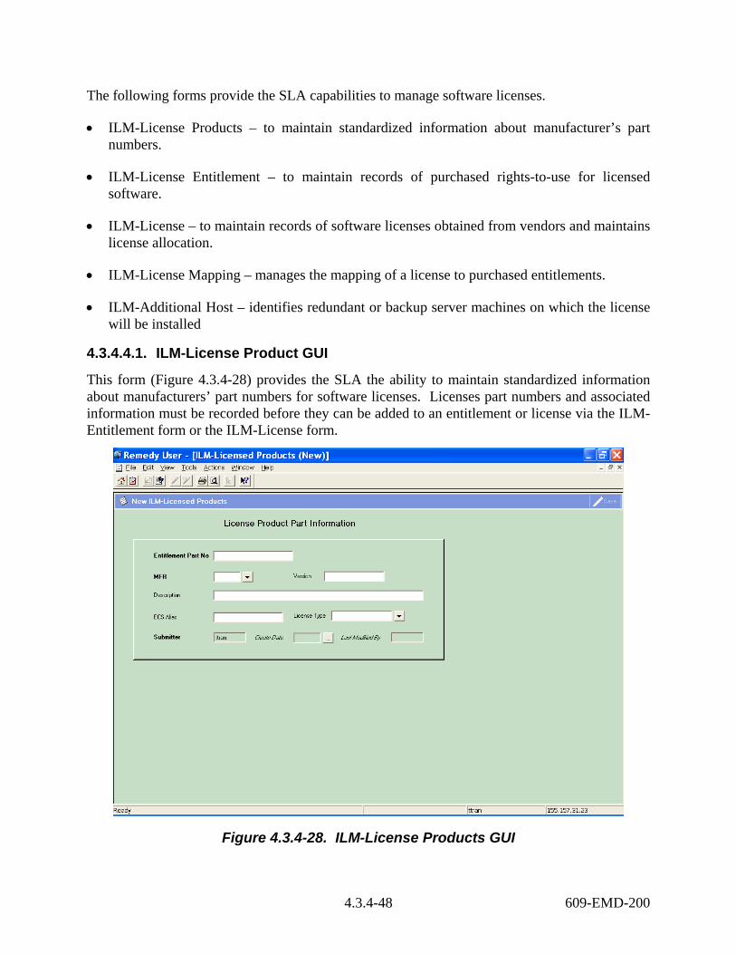
The following forms provide the SLA capabilities to manage software licenses.
• ILM-License Products – to maintain standardized information about manufacturer’s part numbers.
• ILM-License Entitlement – to maintain records of purchased rights-to-use for licensed software.
• ILM-License – to maintain records of software licenses obtained from vendors and maintains license allocation.
• ILM-License Mapping – manages the mapping of a license to purchased entitlements.
• ILM-Additional Host – identifies redundant or backup server machines on which the license will be installed
4.3.4.4.1. ILM-License Product GUI
This form (Figure 4.3.4-28) provides the SLA the ability to maintain standardized information about manufacturers’ part numbers for software licenses. Licenses part numbers and associated information must be recorded before they can be added to an entitlement or license via the ILM-Entitlement form or the ILM-License form.
Figure 4.3.4-28. ILM-License Products GUI
4.3.4-48 609-EMD-200
Table 4.3.4-17 describes the ILM-License Products form fields definitions.
Table 4.3.4-17. ILM-Licensed Products Form Field Descriptions Field Name Data
Type Size Entry Description
Entitlement Part No
Char 34 Required Manufacturer’s or vendor’s part number for the entitlement.
MFR Char 6 Required Code for the manufacturer from whom the item was purchased.
Version Char 34 Optional Version number of the part. Description Char 50 Required Manufacturer’s or vendor’s description for the
entitlement. This field reflects the description of the OEM Part Number entered in the field above.
ECS Alias Char 30 optional Common name used in ECS for the licensed product and all its versions and variants.
License Type Char 16 optional Classification that distinguishes among licenses according to rules of use. Examples include: floating (limited number of concurrent users), nodelocked (limited to use on a single machine), user (limited to use by a certain individual), project (unlimited use anywhere by individuals working on a certain project), site (unlimited use at a single site), etc.
Submitter Char 30 system-supplied
The user whom created the record.
Create Date Date n/a system-supplied
Date the record was created.
Last Modified By Char 30 system-supplied
The last date the record was modified.
4.3.4.4.2 ILM-License Entitlement Form Operators use the ILM-License Entitlement form (Figures 4.3.4-29-4.3.4-31) to maintain records of purchased rights-to-use for licensed software, including how many node and user rights-to-use have been consumed, remain, and are under maintenance. Rights consumed and remaining are computed automatically based on the licenses mapped against it.
4.3.4-49 609-EMD-200
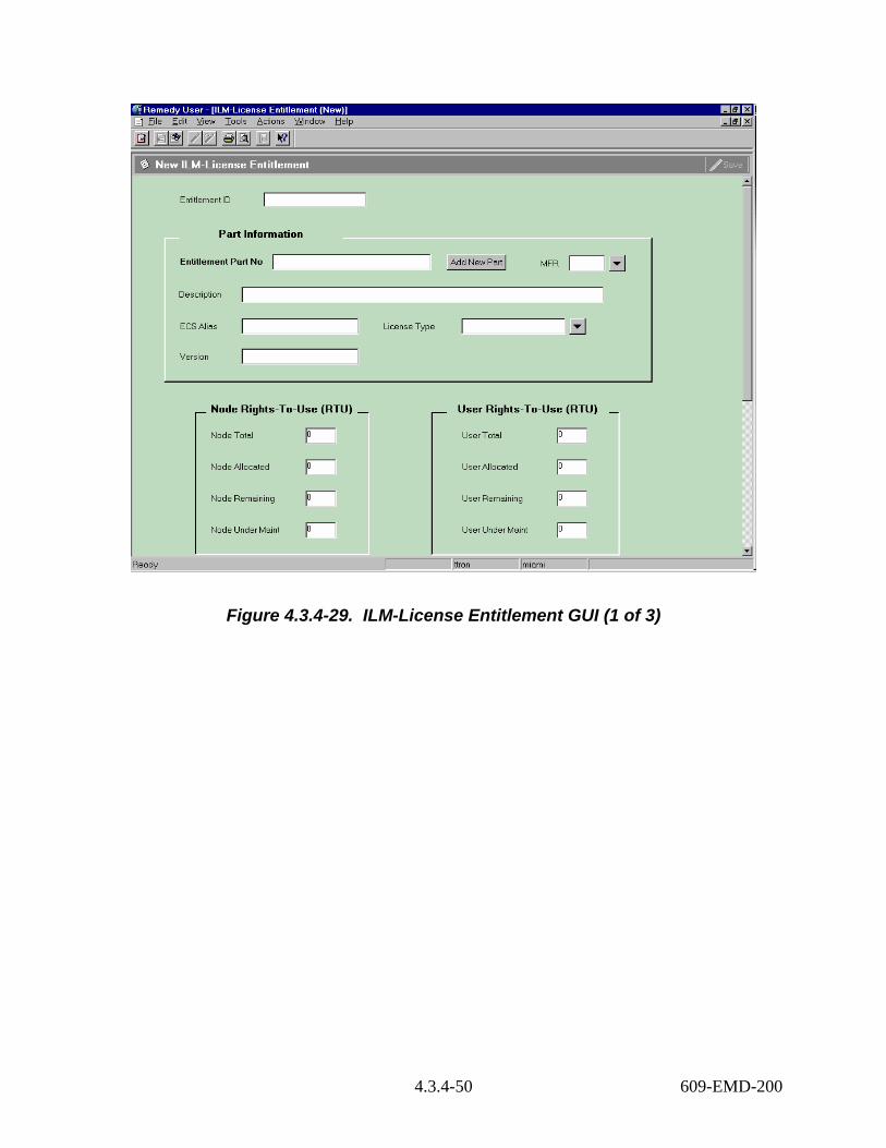
Figure 4.3.4-29. ILM-License Entitlement GUI (1 of 3)
4.3.4-50 609-EMD-200

Figure 4.3.4-30. ILM-License Entitlement GUI (2 of 3)
4.3.4-51 609-EMD-200

Figure 4.3.4-31. ILM-License Entitlement GUI (3 of 3)
Table 4.3.4-18 describes the ILM-License Entitlement form’s field descriptions.
4.3.4-52 609-EMD-200

Table 4.3.4-18. ILM-License Entitlement Form Field Descriptions (1 of 2) Field Name Data
Type Size Entry Description
Entitlement ID Char 10 System supplies
Identifier for a purchased license entitlement.
Entitlement Part No
Char 34 required Manufacturer’s or vendor’s part number for the entitlement.
MFR Char 6 system supplied
Code for the manufacturer from whom the item was purchased. This field reflects the MFR of the entitlement Part No entered in the field above.
Description Char 50 system supplied
Manufacturer’s or vendor’s description for the entitlement. This field reflects the description of the entitlement Part No entered in the field above.
ECS Alias Char 30 system supplied
Common name used in ECS for the licensed product and all its versions and variants. This field reflects the ECS Alias of the entitlement Part No entered in the field above.
License Type Char 16 system supplied
Classification that distinguishes among licenses according to rules of use. This field reflects the license type of the entitlement Part No entered in the field above.
Version Char 34 system supplied
Version number of the part. This field reflects the version of the entitlement Part No entered in the field above.
Rights to Use (RTU) Node/User Total
Integer 8 Optional Quantity of node or user rights-to-use authorized by this purchased entitlement.
Node/User Allocated
Integer 8 system supplied
Quantity of node or user rights under the license entitlement currently allocated by licenses mapped to the entitlement. This value is calculated by the system and reflects the total number of active allocations of those licenses.
Node/User Remaining
Integer 8 system supplied
Quantity of node or user rights under a license entitlement not yet consumed by the mapping of licenses to the entitlement.
Node/User Under Maint
Integer 8 system supplied
Quantity of node or user rights-to-use currently under maintenance.
Vendor ID Char 6 optional Code for the vendor from whom the item was purchased.
PO Number Char 10 optional Identifier of the purchase order against which the item was received.
Receive Date Date n/a optional Date item was received from vendor. Maint Contract ID
Char 10 optional Identifier for the Maintenance Contract under which the item is covered.
Maint Exp Date Date n/a optional Date the maintenance contract expired.
4.3.4-53 609-EMD-200

Table 4.3.4-18. ILM-Entitlement Form Field Descriptions (2 of 2) Field Name Data
Type Size Entry Description
Comment Char 30 Optional Miscellaneous information specific to the item. Submitter Char 30 system-
supplied The user whom created the record.
Create Date Date n/a system-supplied
Date the record was created.
Last Modified By Char 30 system-supplied
The last date the record was modified.
Licenses Page n/a system-supplied
This page lists the licenses that are associated with the license entitlement record.
The following buttons are unique to this form:
• Add New Part – Activates the ILM-License Entitlement Part form. This allows the operator to add new parts.
• Add New License – Displays the ILM-License form (Figure 4.3.4-32) to allow the SLA to add new licenses.
• Adjust RTUs – Facilitates adjustments of the right-to-use numbers.
4.3.4.4.3ILM-License GUI The ILM-License form (Figures 4.3.4-32 – 4.3.4-35) maintains records of software licenses obtained from vendors. This form also maintains records about the hosts and sites to which the licenses have been allocated. Licenses can be mapped to purchase license entitlements so that consumption of license rights can be tracked.
A license is a euphemism for the rights granted a number of user to operate a software product or one or more of the product’s versions or features concurrently on certain machines. These rights are often encoded in a license “key”, but not all products employ such keys.
4.3.4-54 609-EMD-200

Figure 4.3.4-32. ILM-License GUI (1 of 4)
4.3.4-55 609-EMD-200

Figure 4.3.4-33. ILM-License GUI (2 of 4)
4.3.4-56 609-EMD-200
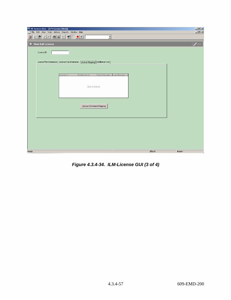
Figure 4.3.4-34. ILM-License GUI (3 of 4)
4.3.4-57 609-EMD-200

Figure 4.3.4-35. ILM-License GUI (4 of 4)
Table 4.3.3-19 provides fields definitions for the ILM-License form.
Table 4.3.4-19. ILM-License Form Field Descriptions (1 of 3) Field Name Data Type Size Entry Description
License ID Char 10 System Supplies
Unique designator for a license.
Entitlement Part No
Char 34 required Manufacturer’s or vendor’s part number for the entitlement.
MFR Char 6 system supplied
Code for the manufacturer from whom the item was purchased. This field reflects the MFR of the entitlement Part No entered in the field above.
Description Char 50 system supplied
Manufacturer’s or vendor’s description for the entitlement. This field reflects the description of the entitlement Part No entered in the field above.
4.3.4-58 609-EMD-200

Table 4.3.4-19. ILM-License Form Field Descriptions (2 of 3) Field Name Data Type Size Entry Description
ECS Alias Char 30 system supplied
Common name used in ECS for the licensed product and all its versions and variants. This field reflects the ECS Alias of the entitlement Part No entered in the field above.
Receive Date Date n/a optional Date the license key and/or data arrived. Version Char 34 system
supplied Version number of the part. This field reflects the version of the entitlement Part No entered in the field above.
Platforms Char 15 optional One or more codes for the types of machines to which the license applies (e.g., Sun, SGI, PC, etc.)
Serial No Char 30 optional Vendor-supplied serial number for the license or the product being licensed.
License Type Char 16 system supplied
Classification that distinguishes among licenses according to rules of use. This field reflects the license type of the entitlement Part No entered in the field above.
Features Char 54 optional Name(s) of one or more features of the licensed product that are covered by the license.
License Manager Char 12 optional Technology employed in managing the license on-line (e.g., flexlm, proprietary, etc.)
License Key Char 50 optional Char of alphanumeric characters that represent the provisions for a license in an encoded form.
Host Name Char 30 optional ECS Name of a machine to which the license is allocated.
Host ID Char 20 optional Host id of the license server machine supplied to the vendor when requesting the license. This is an information only field. Allocations of licenses to machines are accomplished via the License Allocation Manager screen.
Site Char 6 Optional Code for the site to which the license is allocated.Lic Key User RTU Integer 8 optional Number of users authorized by the license to run
the licensed product concurrently on a single network. This value limits the user rights-to-use that can be recorded in the license's allocation records.
Password Char 20 optional Password supplied along with the license key by the vendor. This is an information only field.
Key Exp Date Date n/a optional Date on which the license key is no longer usable.
Comment Char 60 optional Comment to be stored in the record. Submitter Char 30 system-
supplied The user whom created the record.
4.3.4-59 609-EMD-200

Table 4.3.4-19. ILM-License Form Field Descriptions (3 of 3) Field Name Data Type Size Entry Description
Create Date Date n/a system-supplied
Date the record was created.
Last Modified By Char 30 system-supplied
The last date the record was modified.
The following buttons are unique to this form: • Add New Part – Activates the ILM-License Product form. This allows the operator to
add new parts. • Add Additional Host – activates the ILM-Additional host form to allow the SLA to add
redundant host or backup server to the license. • License-Entitlement Mapping - activates the ILM-License Mapping form that allows the
SLA to map the license to the purchased entitlement.
4.3.4.4.4 ILM-License Mapping GUI The ILM-License Mapping form (Figure 4.3.4-36) manages the mapping of a license to purchased entitlements and specifies how many node and/or user rights-to-use the license is consuming from each. The form ensures that:
a) the rights-to-use attributed to an entitlement do not exceed the entitlement's rights remaining;
b) the sum of the rights being attributed to all entitlements do not exceed the rights-to-use for the license.
4.3.4-60 609-EMD-200

Figure 4.3.4-36. ILM-License Mapping GUI
Table 4.3.4-20 describes the fields on the License-Mapping form.
4.3.4-61 609-EMD-200
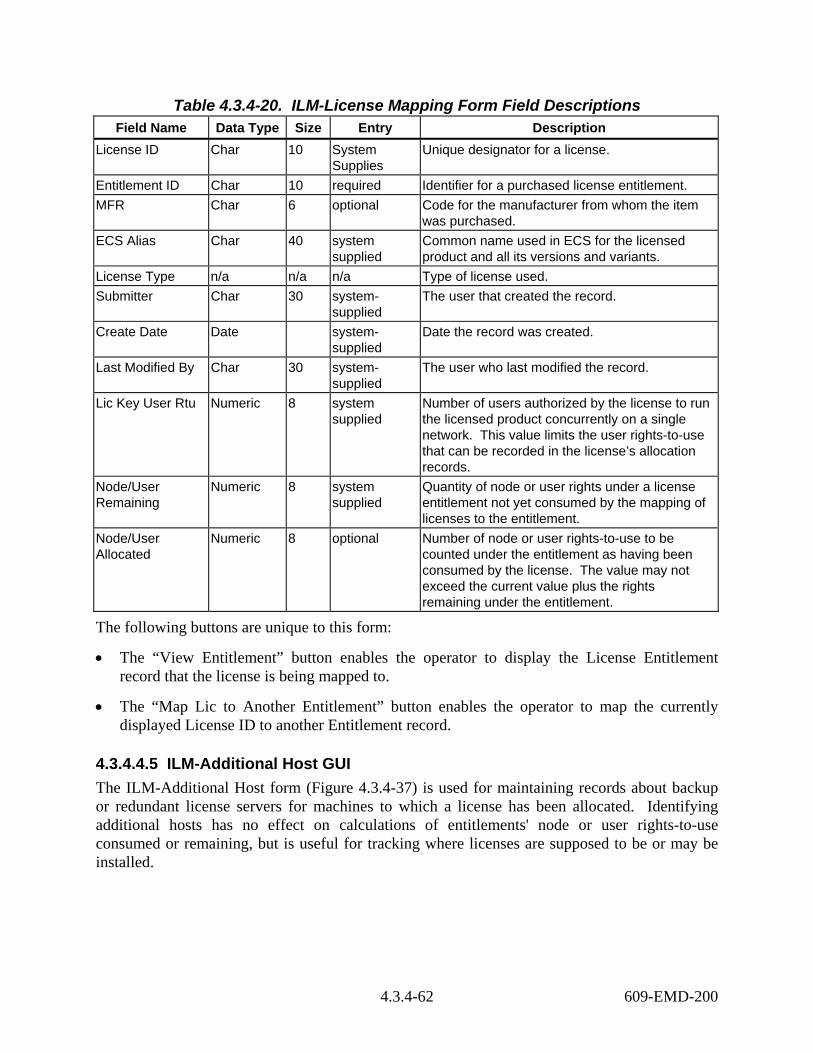
Table 4.3.4-20. ILM-License Mapping Form Field Descriptions Field Name Data Type Size Entry Description
License ID Char 10 System Supplies
Unique designator for a license.
Entitlement ID Char 10 required Identifier for a purchased license entitlement. MFR Char 6 optional Code for the manufacturer from whom the item
was purchased. ECS Alias Char 40 system
supplied Common name used in ECS for the licensed product and all its versions and variants.
License Type n/a n/a n/a Type of license used. Submitter Char 30 system-
supplied The user that created the record.
Create Date Date system-supplied
Date the record was created.
Last Modified By Char 30 system-supplied
The user who last modified the record.
Lic Key User Rtu Numeric 8 system supplied
Number of users authorized by the license to run the licensed product concurrently on a single network. This value limits the user rights-to-use that can be recorded in the license’s allocation records.
Node/User Remaining
Numeric 8 system supplied
Quantity of node or user rights under a license entitlement not yet consumed by the mapping of licenses to the entitlement.
Node/User Allocated
Numeric 8 optional Number of node or user rights-to-use to be counted under the entitlement as having been consumed by the license. The value may not exceed the current value plus the rights remaining under the entitlement.
The following buttons are unique to this form:
• The “View Entitlement” button enables the operator to display the License Entitlement record that the license is being mapped to.
• The “Map Lic to Another Entitlement” button enables the operator to map the currently displayed License ID to another Entitlement record.
4.3.4.4.5 ILM-Additional Host GUI The ILM-Additional Host form (Figure 4.3.4-37) is used for maintaining records about backup or redundant license servers for machines to which a license has been allocated. Identifying additional hosts has no effect on calculations of entitlements' node or user rights-to-use consumed or remaining, but is useful for tracking where licenses are supposed to be or may be installed.
4.3.4-62 609-EMD-200

Figure 4.3.4-37. ILM-Additional Host GUI
Table 4.3.4-21 describes the fields on the ILM-Additional Host form.
4.3.4-63 609-EMD-200

Table 4.3.4-21. ILM-Additional Host Form Field Descriptions Field Name Data
Type Size Entry Description
License ID Char 10 System Supplied
Unique designator for a license. Derived from the displayed license.
ECS Alias Char 30 System Supplied
Common name used in ECS for the licensed product and all its versions and variants.
Host Name Char 30 optional ECS name of a machine that is a backup or redundant license server for the one to which the license is principally allocated.
Host ID Char 20 optional Host id of a machine that is a backup or redundant license server for the one to which the license is principally allocated.
Site Char 6 Optional Code for the site to which the license is allocated.
Submitter Char 30 system-supplied
The user whom created the record.
Create Date Date n/a system-supplied
Date the record was created.
Last Modified By Char 30 system-supplied
The last date the record was modified.
The “Add Another Host to License” Button enables the operator to allocated a license to more than one host. This is usually done to assign licenses to backup or redundant license servers
4.3.4.5 ILM-System Parameters The ILM-System Parameters form (Figure 4.3.4-38) is for maintaining system-wide Remedy-ILM parameters and is principally used for initializing certain identifier fields.
Several fields have particular significance for ILM. The Site ID field contains the code for the ECS site where the operator’s copy of Remedy is installed. This field is interrogated by ILM processes that have to determine which assets belong to the local site. The Next EIN ID field is used by Remedy to keep track of the most recently used, automatically-assigned EIN. Remedy increment the field whenever an operator creates a new EIN when creating records via ILM-EIN form.
4.3.4-64 609-EMD-200

Figure 4.3.4-38. ILM-System Parameters GUI
Table 4.3.4-22 describes the fields on the ILM-System Parameters form.
Table 4.3.4-22. ILM-System Parameters Form Field Descriptions Field Name Data Type Size Entry Description
Site Char 6 required Code that identifies the ECS site where this Remedy system is installed.
Next EIN ID Char 20 system-supplied, but modifiable
Field containing the next sequentially-available identifier when assigning EIN numbers automatically.
Next MWO Number
Char 10 system-supplied, but modifiable
Field containing the next MWO number to be used.
Next Entitlement ID
Char 10 system-supplied, but modifiable
Field containing the next entitlement id number to be used.
Next License ID Char 10 system-supplied, but modifiable
Field containing the next license id number to be used.
4.3.4-65 609-EMD-200

4.3.4.6 User GUI The User form, shown in Figure 4.3.4-39, is used by the administrator to add, modify or remove users of the Action Request (AR) System. The "User" form is used in conjunction with the "Group" form to provide users with permissions ultimately determining which operations individual users can perform and which forms and fields they can access. For more information on the "User" form and the AR System access control, refer to the Action Request System Server Administrator's Guide. Table 4.3.4-23 provides descriptions of the User Form.
Figure 4.3.4-39. User GUI
4.3.4-66 609-EMD-200

Table 4.3.4-23. User Form Field Descriptions Field Name Data Type Size Entry Description
Entry-Id Character 15 System generated
Entry ID of user
Status Selection * Required Is user current or not as shown by the “current” button.
License Type Selection * Required What type of license does this user have? (e.g., read, fixed, floating)
Login name Character 30 Required Login name of user Password Character 30 Optional Password of User Email Address Character 255 Required E-mail address of User Group list Character 255 Optional Groups to which the user belongs Full Name Character 128 Required Full Name of User Phone Number Character 55 Required Phone Number of User Home DAAC Character 55 Required Home DAAC of User Default Notify Mechanism
Selection * Optional Notification method (e.g., None, Notifier, and Email buttons.)
Full Text License Type Selection n/a Required The Full Text License capability is not available. So, the selection value should be “None.”
Creator Character 30 Required Person who created the user account Create-date Date/Time 17 System
generated Date and time the entry was created at the present site (mm/dd/yy hh:mm:ss)
Last-modified-by Character 30 System generated
User ID of person that last modified the user entry
Modified-date Date/Time 17 System generated
Date and time of last modification to user entry (mm/dd/yy hh:mm:ss)
Instance ID Character 38 Optional A Remedy reserve field for Remedy’s use only.
Object ID Character 38 Optional A Remedy reserver field for Remedy’s use only.
Note: the size of a field with a "selection" data type can vary and the size is automatically adjusted to the size of the item selected from the selection list.
4.3.4.7 Remedy’s Admin Tool GUI The Remedy Administrator Tool is the tool one uses to create, modify, and delete Remedy objects (e.g. forms and menus). Figure 4.3.4-40 shows the main Administrator Tool GUI and its starting screen, the server window, and the workflow objects categories.
4.3.4-67 609-EMD-200

Figure 4.3.4-40. Admin Tool GUI
Table 4.3.4-24 provides a description of the Admin Tool GUI Workflow objects. For more information on these options, see Remedy’s Action Request System Administrator's Guide, Vol. 1, Chapter 4, and/or the Remedy Administrator Tutorial using the Administrator Tool’s Help menu.
Table 4.3.4-24. Admin Tool GUI, Workflow Object Descriptions Workflow Object Size Entry Description
Forms Variable System Generated List of available forms. Active links Variable System Generated List of available active links. Filters Variable System Generated List of available filters. Escalations Variable System Generated List of available escalations. Guides Variable System Generated List of available guides. Applications Variable System Generated List of available applications Packing lists Variable System Generated List of available packing lists Menus Variable System Generated List of available menus Groups Variable System Generated List of available groups
4.3.4.8 Databases Remedy’s Action Request System uses the Sybase database called ARSystem that resides on the Remedy server machines. Tables and columns are created, modified, and deleted when forms are built and edited. This is all done automatically and is invisible to the user.
4.3.4-68 609-EMD-200

4.3.4.9 Special Constraints Note that while ILM forms are open to all operators, and operators have view privileges to the user form, only system administrators have the ability to modify forms and tools presented in this section. Privileges are set according to DAAC policy.
4.3.4.10 Outputs Output from Remedy’s Action Request System (besides output to the screen in the form of its GUIs) is in the form of a report either to the printer or to a file (reports discussed in Section 4.3.4.16) or a log entry as shown in Table 4.3.4-25.
In the Remedy aradmin tool, you may enable and disable error logging at any time. Select File-> Server Information-> Log Files to display the current location of log files that have been enabled. The format of the messages is similar to the Unix syslog as seen in this example:
Table 4.3.4-25. Remedy Log File Messages Example Mon Feb 23 16:28:16 1998 390600 : Failure during SQL operation to the database (ARERR 552) Mon Feb 23 16:28:16 1998 Unable to connect: SQL Server is unavailable or does not exist. (Sybase 20009) : Connection refused Mon Feb 23 16:28:16 1998 Unable to connect: SQL Server is unavailable or does not exist. (Sybase 20009) : Connection refused
4.3.4.11 Event and Error Messages For Remedy’s Action Request System’s system messages see the Action Request System Error Messages Guide.
Table 4.3.4-26 lists non-system failure related messages that appear on the operator’s screen.
Table 4.3.4-26. Non-System Failure Related Error Messages (1 of 6) Error Message Char Cause Action
Inventory Management Parent EIN does not exist. Enter the correct Parent EIN.
Attempting to associate a component EIN to a Parent EIN that does not exist.
Enter the correct Parent EIN
Parent EIN, $Parent EIN$, is a component. Please enter the correct Parent EIN number.
Attempting to associate a component EIN to a Parent EIN that is a component to another EIN Structure
Enter the correct Parent EIN.
Parent EIN, $Parent EIN$, is not hardware. Enter the correct Parent EIN!
Attempting to associate a component EIN to a Parent EIN that is not hardware.
Enter the correct Parent EIN.
Part not found. Add new part into the part table or enter the correct part no.
Attempting to enter a part number that does not exist in the database.
Enter the correct Part No into the ILM-OEM Parts form or enter the correct part no.
4.3.4-69 609-EMD-200

Table 4.3.4-26. Non-System Failure Related Error Messages (2 of 6) Error Message Char Cause Action
Part Number, $Part No$, already exists. Enter the correct Part Number!
Attempting to add a new Part No enter the ILM-Oem Parts form where the Part No already existed in the form.
Enter the correct Part number.
EIN is a component to Parent EIN. Update the Parent EIN’s ECS name instead.
Attempting to update an ECS Name of a component EIN.
Update the Parent EIN’s ECS Name.
New Parent EIN is the same as the old Parent EIN. Enter the correct new Parent EIN.
Attempting to relocate to relocate an item to the same Parent EIN.
Enter the correct New Parent EIN.
EIN already existed. Enter the correct EIN.
Attempting to create a new EIN that is already existed in the database.
Enter the correct EIN number.
A record for Location, $Location$, with Building, $Building$, already exists. Enter the correct Location and its associated Building!
Attempting to create a new location in the ILM-Inventory location form where the combination of location and building values already existed in the form.
Do not enter the new location and use the existed one.
EIN ($EIN$) is a Parent to EIN ($EIN is Parent$). Can not assign a Parent to another Parent structure.
Attempting to assign a Parent EIN as a component to an EIN structure.
Verify the Component EIN and the Parent EIN.
Audit Date ($Audit Date$) can not be greater than current date. Enter the correct audit date.
Attempting to update the audit date to a date greater than the current date.
Enter the correct audit date.
Receive Date ($Receive Date$) can not be greater than the current date ($DATE$). Enter the correct receive date.
Attempting to update the receive date to a date greater than the current date.
Enter the correct receive date.
Vendor ID, $Vendor ID$, already exists. Enter the correct Vendor ID!
Attempting to add a new vendor id that already existed in the ILM-Vendor-MFR form.
Use the existing Vendor ID if the vendor name is the same. If the vendor name is not the same, use another code to define the new vendor.
Site, $Site$, already exists. Enter the correct Site!
Attempting to add a site code that already existed in the ILM-Site form.
Use the existing site code.
Item Status, $Item Status$, already exists. Enter the correct Item Status!
Attempting to add a new item status that already existed in the ILM-Status Code form.
Enter the correct item status.
EIN Transactions Parent EIN field is a required field. Enter a Parent EIN value into the Parent EIN field.
Attempting to perform an EIN transacion where the Parent EIN value is not provided in the Parent EIN field.
Enter the correct Parent EIN value into the Parent EIN.
4.3.4-70 609-EMD-200
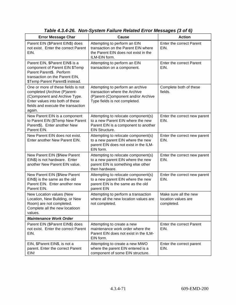
Table 4.3.4-26. Non-System Failure Related Error Messages (3 of 6) Error Message Char Cause Action
Parent EIN ($Parent EIN$) does not exist. Enter the correct Parent EIN.
Attempting to perform an EIN transaction on the Parent EIN where the Parent EIN does not exist in the ILM-EIN form.
Enter the correct Parent EIN.
Parent EIN, $Parent EIN$ is a component of Parent EIN $Temp Parent Parent$. Perform transaction on the Parent EIN, $Temp Parent Parent$ instead.
Attempting to perform an EIN transaction on a component.
Enter the correct Parent EIN.
One or more of these fields is not completed (Archive (P)arent-(C)omponent and Archive Type. Enter values into both of these fields and execute the transaction again.
Attempting to perform an archive transaction where the Archive (P)arent-(C)omponent and/or Archive Type fields is not completed.
Complete both of these fields.
New Parent EIN is a component to Parent EIN ($Temp New Parent Parent$). Enter another New Parent EIN.
Attempting to relocate component(s) to a new Parent EIN where the new Parent EIN is a component to another EIN Structure.
Enter the correct new parent EIN.
New Parent EIN does not exist. Enter another New Parent EIN.
Attempting to relocate component(s) to a new parent EIN where the new parent EIN does not exist in the ILM-EIN form.
Enter the correct new parent EIN.
New Parent EIN ($New Parent EIN$) is not hardware. Enter another New Parent EIN value.
Attempting to relocate component(s) to a new parent EIN where the new parent EIN is something else other then hardware.
Enter the correct new parent EIN.
New Parent EIN ($New Parent EIN$) is the same as the old Parent EIN. Enter another new Parent EIN.
Attempting to relocate component(s) to a new parent EIN where the new parent EIN is the same as the old parent EIN
Enter the correct new parent EIN.
New Location values (New Location, New Building, or New Room) are not completed. Complete all the new locatioon values.
Attempting to perform a transaction where all the new location values are not completed.
Make sure all the new location values are completed.
Maintenance Work Order Parent EIN ($Parent EIN$) does not exist. Enter the correct Parent EIN.
Attempting to create a new maintenance work order where the Parent EIN does not exist in the ILM-EIN form.
Enter the correct Parent EIN.
EIN, $Parent EIN$, is not a parent. Enter the correct Parent EIN!
Attempting to create a new MWO where the parent EIN entered is a component of some EIN structure.
Enter the correct parent EIN.
4.3.4-71 609-EMD-200

Table 4.3.4-26. Non-System Failure Related Error Messages (4 of 6) Error Message Char Cause Action
ALDT 1 End Date-Time ($ALDT End Date-Time$) can not be greater than current date.
Attempting to enter an ALDT End Date-Time that is greater than the current date and time.
Enter the correct ALDT End date-time.
Notification Date ($Notification Date-Time$) can not be greater than current date.
Attempting to enter a notificcation Date-Time that is greater than the current date and time.
Enter the correct notification date-time.
Vendor Complete Date-Time ($Vendor Complete Date-Time$) can not be greater than current date.
Attempting to enter an vendor complete Date-Time that is greater than the current date and time.
Enter the correct vendor complete date-time.
Vendor Call Date-Time ($Vendor Call Date-Time$) can not be greater than current date.
Attempting to enter an vendor call Date-Time that is greater than the current date and time.
Enter the correct vendor call date-time.
ALDT Start Date-Time ($ALDT Start Date-Time$) can not be greater than current date.
Attempting to enter an ALDT start Date-Time that is greater than the current date and time.
Enter the correct ALDT start date-time.
Failure Date ($Failure Date-Time$) can not be greater than current date.
Attempting to enter an failure Date-Time that is greater than the current date and time.
Enter the correct failure date-time.
Vendor Arrive Date-Time ($Vendor Arrive Date-Time$) can not be greater than current date.
Attempting to enter an vendor arrive Date-Time that is greater than the current date and time.
Enter the correct vendor arrive date-time.
Vendor Initial Response Date-Time ($Vendor Initial Resp Date-Time$) can not be greater than current date.
Attempting to enter an vendor initial response Date-Time that is greater than the current date and time.
Enter the correct vendor intial response date-time.
The MWO must already be created and you must have the MWO displayed in a Search/Modify window before clicking the Add Fail-Replacement Component Button!
Attempting to add a new work order line item where the work order information is blank.
Use the ILM-MWO form to find the appropriate work order and press the “Add Fail-Replacement Component” button to start adding line items to that work order.
Component EIN is the same as the MWO Parent EIN. Enter the correct component EIN.
Attempting to add a work order line item where the component EIN is the same as the MWO’s Parent EIN.
Enter the correct component EIN.
New Parent EIN is the same as the MWO's Parent EIN. Enter the correct New Parent EIN.
Attempting to add a work order line item to move a component to a new EIN structure where the new parent EIN is the same as the MWO’s Parent EIN.
Enter the correct new parent EIN value.
New Parent EIN ($New Parent EIN$) is a component to Parent EIN ($New Parent EIN Parent$). Enter the correct New Parent EIN value
Attempting to add a work order line item to move a component to a new EIN structure where the new parent EIN is the same as the MWO’s Parent EIN.
Enter the correct new parent EIN value.
4.3.4-72 609-EMD-200

Table 4.3.4-26. Non-System-Failure Related Error Messages (5 of 6) Error Message Char Cause Action
New Parent EIN does not exist. Enter the correct New Parent EIN.
Attempting to add a work order line item to move a component to a new EIN structure where the new parent EIN does not exist in the ILM-EIN form.
Enter the correct new parent EIN value.
New Parent EIN is not hardware. Enter the correct New Parent EIN value.
Attempting to add a work order line item to move a component to a new EIN structure where the new parent EIN in not hardware.
Enter the correct new parent EIN value.
Component EIN is a parent. Enter the correct Component EIN value.
Attempting to add a work order line item where the component EIN is a parent.
Enter the correct component EIN value.
Line Item does not have the correct event type and maint code. Enter the correct event type and maint code.
Entering the incorrect combination of event type and maint code in the ILM-MWO Line Item form.
Enter the correct event type and maint code.
License Management Entitlement Part No does not exist. Enter the correct part number or add the new part into the ILM-License Entitlement Part form.
Attempting to associate entitlement with an Entitlement Part no that does not exist in the ILM-License Entitlement Form.
Enter the correct part number or add the new part into the ILM-License Entitlement Part form.
Contract ID, $Contract ID$, already exists. Enter the correct Contract ID!
Attempting to associate a license entitlement with a contract ID where the contract id does not exist in the ILM-Maint contract form.
Enter the correct contract ID.
Entitlement ID does not exist. Enter the correct Entitlement ID.
Attempting to map a license to a purchased entitlement that does not exist in the ILM-Entitlement form.
Enter the correct Entitlement ID.
Node allocated is greater than Node remaining. Reduce number of Right-To-Use or enter another Entitlement ID.
Attempting to map a license to an entitlement where the entitlement node remaining is less than the amount allocating.
Reduce the number of node allocated.
User Allocated is greater than License Key User RTU allocated to the license. Enter the correct User Allocated value.
Attempting to map a license to an entitlement where the user allocated is greater than the license key user rights-to-use.
Reduce the user allocated to equal to or less than the license key RTU.
User Allocated is greater than User RTU Remaining. Lower User Allocated or Enter another Entitlement ID.
Attempting to map a license to an entitlement where the user allocated is greater than the entitlement user rights-to-use remaining
Reduce the user allocated.
This license right-to-use had already been mapped to entitlement $Ent ID Holder$.
Attempting to map a node lock license to more than one entitlements.
Do not map the license to another entitlement.
4.3.4-73 609-EMD-200

Table 4.3.4-26. Non-System-Failure Related Error Messages (6 of 6) Error Message Char Cause Action
Total user allocated ($Total User Allocated$) is greater than the lic key user RTU. Reduce number of User Allocated
Attempting to map a license to entitlements where the total user allocated is greater than the license key user rights-to-use.
Reduce the user allocated to equal to or less than the license key RTU.
Node allocated or User allocated has not been assigned to this Entitlement ID ($Entitlement ID$).
Attempting to map a license to an entitlement where the user did not enter any value in the Node or user allocated.
Enter node or user allocated to map against the entitlement.
Node Allocated can not be greater than one for nodelock licenses. Enter 1 to allocate 1 Right-To-Use for this Nodelock license.
Attempting to allocate more than 1 node rights-to-use for a node lock license.
reduce the number of node rtu allocated to 1.
Combination of Entitlement Part No-MFR and Version $Temp PN_MFR_Ver$ already existed. Enter the correct Entitlement Part No.
Attempting to add a new entitlement part into the ILM-License Products form where the combination of the Entitlement Part No, MFR, and version already existed in the database.
use the existing entitlement part information.
4.3.4.12 Reports Operator may generate ad-hoc reports from any forms (see AR System 4.x User manual on Reporting). However, ILM provides a set of predefined reports that operator can generate through Tools Report from the Menu bar. Table 4.3.4-27 identifies the predefined reports available in ILM. The figures that follow (Figures 4.3.4-41 through 4.3.4-57) present a sample of each.
Table 4.3.4-27. ILM Reports (1 of 2) Report Type Report Description
Inventory Management Install/Receipt Report A report that describes an operator-specified EIN item together with all of its
associated components order by EIN number. See Figure 4.3.4-42. Installation Report A report that describes an operator-specified EIN item together with its
components having status “I” (for installed). See Figure 4.3.4-43. Parent EIN Report Provides a listing of only Parent items. See Figure 4.3.4-44. Parent EIN and total System Cost Report
Provides a listing of only Parent items and the total system cost for each Parent. See Figure 4.3.4-45.
Inventory Report Provides an ASCII formatted report identifying the inventory items by Parent EIN according to the operator-specified criteria. See Figure 4.3.4-46.
ECS Shipping Report Provides a listing of items that were shipped within an operator-specified time frame. See Figure 4.3.4-47.
Quarterly Property Management Report
Provides a list of contractor-acquired equipment items by quarter, sorted by Mfr and product description. See Figure 4.3.4-48.
4.3.4-74 609-EMD-200

Table 4.3.4-27. ILM Reports (2 of 2) Report Type Report Description
Purchase Order Cost Report
Provides a list of EINs and their cost associated with an operator-specified purchase order. See Figure 4.3.4-49.
Cost - Selected ECS Managed Property
Provides the quantity and total cost of operator-selected EINs, grouped by type of inventory (Hardware, Software, Consumable, i.e.). See Figure 4.3.4-50.
EIN Transaction History
A list of the transactions processed for operator-specified items during an operator-specified timeframe, sorted by EIN number and “from” location. See Figure 4.3.4-51.
Spare Equipment Report
Provides a list of spare equipment for a selected site or system-wide report. See Figure 4.3.4-52.
Maintenance Management Maintenance Work Order Verification Report
A full description of operator-selected work orders and the items undergoing maintenance action that they cover. See Figure 4.3.4-53.
Maintenance Contract Report
Provides a list of operator-specified maintenance contract and all the associated items the contract covers. See Figure 4.3.4-54.
RMA Work Order Report
Provides an ASCII formatted spreadsheet formatted report with embedded formulas for RMA data. See Figure 4.3.4-55.
License Management License Entitlements Status Report
Lists the status of current license entitlements for licensed software products, sorted by software product, version, and license type. See Figure 4.3.4-56.
License Allocations by Product Report
Lists license allocations for licensed software products, sorted by product, version, and host name. See Figure 4.3.4-57.
License Allocations by Host Report
Lists license allocations, sorted by host name and ECS part alias. See Figure 4.3.4-58.
4.3.4-75 609-EMD-200
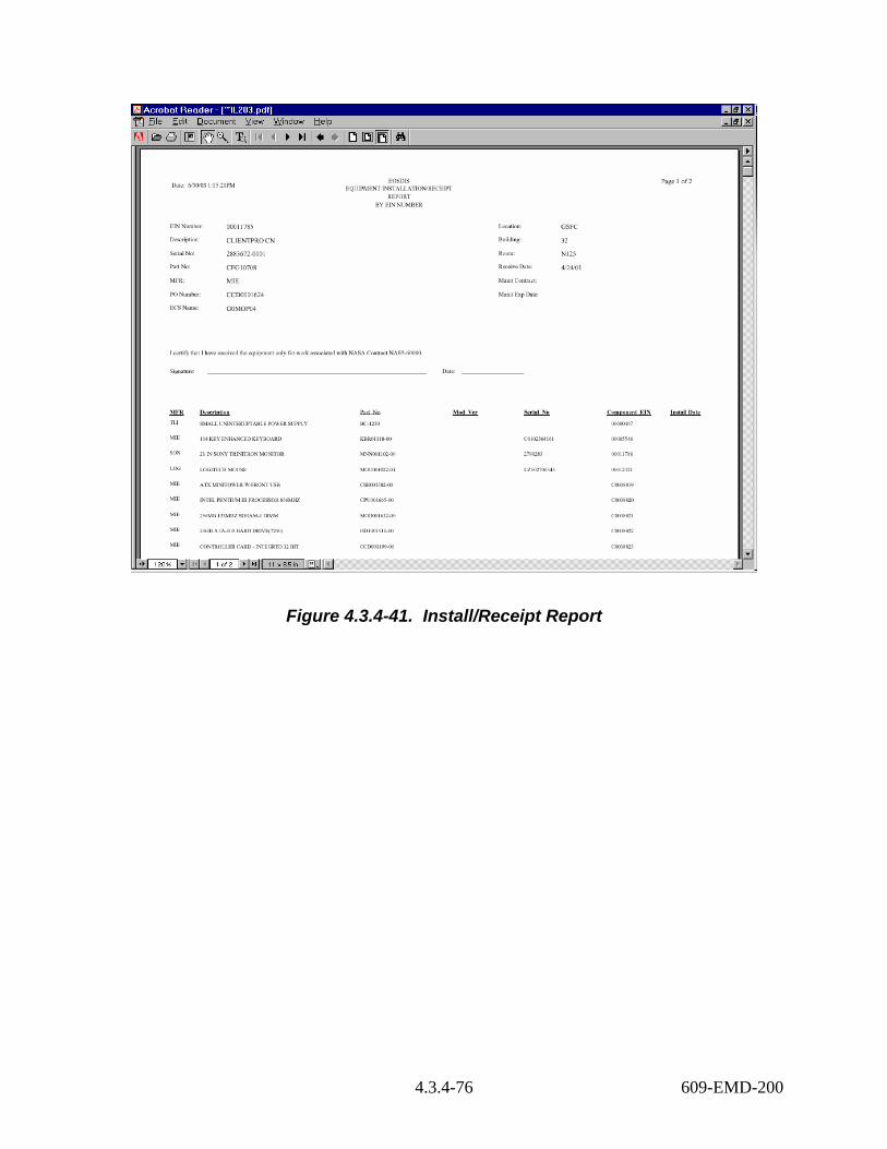
Figure 4.3.4-41. Install/Receipt Report
4.3.4-76 609-EMD-200
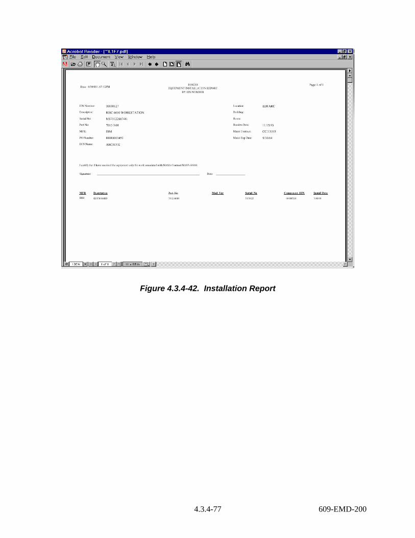
Figure 4.3.4-42. Installation Report
4.3.4-77 609-EMD-200
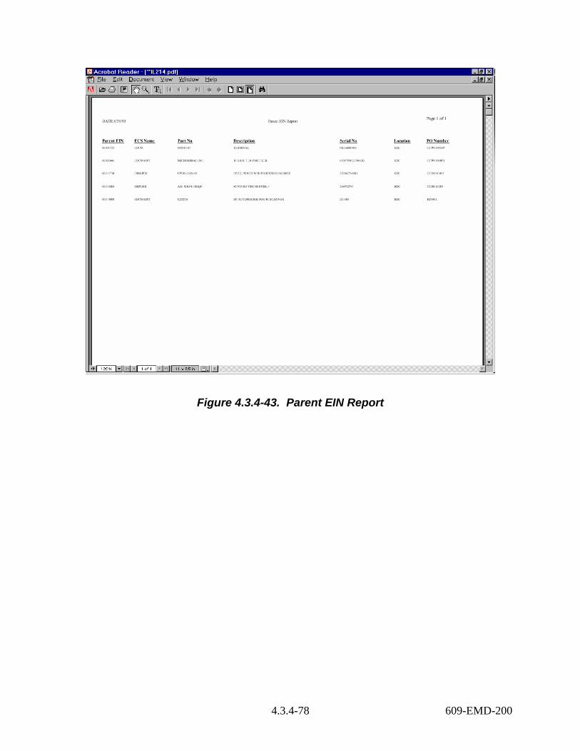
Figure 4.3.4-43. Parent EIN Report
4.3.4-78 609-EMD-200

Figure 4.3.4-44. Parent EIN and Total System Cost Report
4.3.4-79 609-EMD-200

4.3.4-80 609-EMD-200
Parent EIN Part EIN Mfr ECS Name Audit Date Stat Part Num Serial Num Unit Cost Product Description Location Bldg Room Code PO Num Date Rec'd Vendor
00001838 00001838 SUN n0dms04 2/6/02 I A12-UBA1-1E-064AB
645F0AA4 $8,797.00 Ultra 1 System NSIDC NSIDC 209 H CCW0005354 12/2/96 SUN
00001838 00001891 SUN n0dms04 2/6/02 I X5203A 645G0830 $1,035.00 UniPak - 4.2 GB 5400 RPM FW SCSI-2 NSIDC NSIDC 209 H CCW0005354 12/18/96 SUN
00001838 00003491 SUN n0dms04 2/6/02 I X267A 9843KN4545 $5,000.00 Color Monitor - 20 IN NSIDC NSIDC 209 H CCW0005354 12/2/96 SUN
00001838 00006793 SUN n0dms04 2/6/02 I NE SUN1 LZB64001097 $0.00 Mouse - 3 Button Track Ball NSIDC NSIDC 209 H CCW0005354 12/2/96 SUN
00001838 00006794 SUN n0dms04 2/6/02 I 320-1233-02 9626371319 $0.00 Keyboard NSIDC NSIDC 209 H CCW0005354 12/2/96 SUN
00001838 C0009132 SUN n0dms04 2/6/02 I X1025A 12603 $1,500.00 FDDI SINGLE ATTACH SBUS CARD NSIDC NSIDC 209 H CCW0005354 12/2/96 SUN
00001838 C0009133 SUN n0dms04 2/6/02 I X132P 501282278476877
$0.00 Memory - 32MB RAM Expansion (1x32 NSIDC NSIDC 209 H CCW0005354 12/2/96 SUN
00001838 C0009134 SUN n0dms04 2/6/02 I X132P 501262278476942
$0.00 Memory - 32MB RAM Expansion (1x32 NSIDC NSIDC 209 H CCW0005354 12/2/96 SUN
00001838 C0009135 SUN n0dms04 2/6/02 I X3500A $0.00 Country Kit NSIDC NSIDC 209 H CCW0005354 12/2/96 SUN 00001838 C0009136 SUN n0dms04 2/6/02 I X6001A 9625201083 $90.00 Floppy Drive - 3.5 IN Disk Drive-1 NSIDC NSIDC 209 H CCW0005354 12/2/96 SUN 00001838 C0009137 SUN n0dms04 2/6/02 I X6153A 9647723061 $240.00 CD ROM - Internal SUNCD 4 NSIDC NSIDC 209 H CCW0005354 12/2/96 SUN 00001838 C0009839 SUN n0dms04 2/6/02 I 370-2286-01 9643604099 $0.00 Hard Drive - Internal for X5204A NSIDC NSIDC 209 H CCW0005354 12/18/96 SUN 00001838 C0045377 SUN n0dms04 6/25/02 I X5237A 0145KP6EMS $479.20 ULTRA SCSI DISK DRIVE, 18GB INTERN NSIDC NSIDC 209 H CCD0002848 11/27/01 SUN 00001838 C0149507 SUN n0dms04 1/27/99 I SOLD-C $45.00 Solaris Media for Servers NSIDC NSIDC 209 S CCW0005354 12/2/96 SUN 00001839 00001839 SUN n0mos20 2/6/02 I A12-UBA1-
1E-064AB 645F0B2C $8,797.00 Ultra 1 System NSIDC NSIDC 252 H CCW0005354 12/2/96 SUN
00001839 00001890 SUN n0mos20 2/6/02 I X5203A 645G0868 $1,035.00 UniPak - 4.2 GB 5400 RPM FW SCSI-2 NSIDC NSIDC 252 H CCW0005354 12/18/96 SUN SUN 00001839 00003494 SUN n0mos20 2/6/02 I X267A 9647GI3704 $5,000.00 Color Monitor - 20 IN NSIDC NSIDC 252 H CCW0005354 4/3/00
00001839 00006771 SUN n0mos20 2/6/02 I 320-1233-02 9626371388 $0.00 Keyboard NSIDC NSIDC 252 H CCW0005354 12/2/96 SUN 00001839 00006772 SUN n0mos20 2/6/02 I NE SUN1 LZB64001084 $0.00 Mouse - 3 Button Track Ball NSIDC NSIDC 252 H CCW0005354 12/2/96 SUN 00001839 C0009138 SUN n0mos20 2/6/02 I 370-2040-03 9643547711 $0.00 Hard Drive - 2.1 GB Internal NSIDC NSIDC 252 H CCW0005354 12/2/96 SUN 00001839 C0009139 SUN n0mos20 2/6/02 I X1025A 11748 $1,500.00 FDDI SINGLE ATTACH SBUS CARD NSIDC NSIDC 252 H CCW0005354 12/2/96 SUN 00001839 C0009140 SUN n0mos20 2/6/02 I X132P 50126227949
5644 $0.00 Memory - 32MB RAM Expansion (1x32 NSIDC NSIDC 252 H CCW0005354 12/2/96 SUN
00001839 C0009141 SUN n0mos20 2/6/02 I X132P 501262279495714
$0.00 Memory - 32MB RAM Expansion (1x32 NSIDC NSIDC 252 H CCW0005354 12/2/96 SUN
00001839 C0009142 SUN n0mos20 2/6/02 I X3500A $0.00 Country Kit NSIDC NSIDC 252 H CCW0005354 12/2/96 SUN 00001839 C0009143 SUN n0mos20 2/6/02 I X6001A 9625201087 $90.00 Floppy Drive - 3.5 IN Disk Drive-1 NSIDC NSIDC 252 H CCW0005354 12/2/96 SUN 00001839 C0009144 SUN n0mos20 2/6/02 I X6153A 6Y50C01029 $240.00 CD ROM - Internal SUNCD 4 NSIDC NSIDC 252 H CCW0005354 12/2/96 SUN
SUN SUN
00001839 C0009838 SUN n0mos20 2/6/02 I 370-2286-01 9643604145 $0.00 Hard Drive - Internal for X5204A NSIDC NSIDC 252 H CCW0005354 12/18/9600001839 C0038808 SUN n0mos20 2/6/02 I 501-2961 017403 $0.00 System Board NSIDC NSIDC 252 H CCW0005354 4/16/01
SUN 00001839 C0149508 SUN n0mos20 1/27/99 I SOLD-C $45.00 Solaris Media for Servers NSIDC NSIDC 252 S CCW0005354 12/2/96
Figure 4.3.4-45. Inventory Report

Figure 4.3.4-46. ECS Shipping Report
4.3.4-81 609-EMD-200

Figure 4.3.4-47. Quarterly Property Management Report
4.3.4-82 609-EMD-200

Figure 4.3.4-48. Purchase Order Cost Report
4.3.4-83 609-EMD-200

Figure 4.3.4-49. Cost - Select ECS Managed Property Report
4.3.4-84 609-EMD-200

Figure 4.3.4-50. EIN Transaction History Report
4.3.4-85 609-EMD-200

Figure 4.3.4-51. Spare Equipment Report
4.3.4-86 609-EMD-200
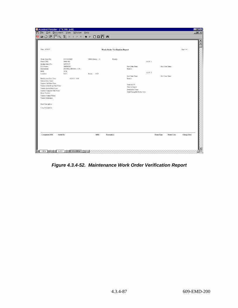
Figure 4.3.4-52. Maintenance Work Order Verification Report
4.3.4-87 609-EMD-200

Figure 4.3.4-53. Maintenance Contract Report
4.3.4-88 609-EMD-200

4.3.4-89 609-EMD-200
Work Order
MFR Description of
System Down
System Name
Site Date/Time Partially/Capable
Total Partially Capable
Time (HRS)
Date/Time System Down
Date Returned
to Operation
Total Down Time (HRS)
Restore Time
Problem Description & Solution
Notes
EDC0000509
SGI RACK SERVER BASIC CHASIS
e0drg12 EDC 10/16/02 9:00
10/16/02 9:00
10/16/02 10:00
1.0 1.0 System board crashed due to bad node board.
Downtime was the result of troubleshooting and repair actions. System took an hour to restore but was operational.
LaR0000269
STK 9940A STK Powerderhorn silo2
LaRC 10/15/02 8:00
28.0 10/16/02 12:00
Bad drive. Replace drive.
EDC0000498
STK Small Communications Rack
e0hippi1 EDC 09/30/02 5:15
224.7 09/30/02 16:00
Bad HIPPI fiber Channel card going to e0drg12.
No Down time associated because Ops had an alternative path GB router.
EDC0000500
SUN Enterprise 4000 Enclosure 8-Slot Card Ca
e0sps04 EDC 09/09/02 2:45
8.3 09/09/02 11:00
There are redundanct cpu boards with memory.
32MB simm had parity errors causing box to reboot.
Figure 4.3.4-54. RMA Report

Figure 4.3.4-55. License Entitlements Status Report
4.3.4-90 609-EMD-200
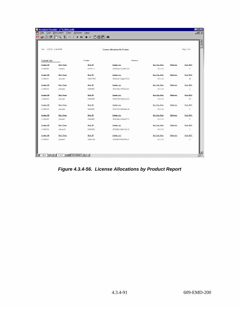
Figure 4.3.4-56. License Allocations by Product Report
4.3.4-91 609-EMD-200

Figure 4.3.4-57. License Allocations by Host Report
4.3.4-92 609-EMD-200

4.3.5 FLEXnet Publisher FLEXnet (formerly FLEXlm) is a commercially available network license management product from Acresso Software that helps ECS sites administer licenses and enforce licensing provisions for FLEXnet-enabled COTS software. It enforces licensing provisions based on information from vendor-provided license keys and lets license administrators allow, deny, or reserve check out of licenses based on user, host, or display. FLEXnet handles floating (concurrent use) licenses, node locked licenses, and combinations of the two.
FLEXnet processing elements include license manager daemons, vendor daemons, license files, and FLEXnet-enabled applications. One or more license manager daemons control vendor daemon operations and enables client applications to contact them. Vendor daemons grant or deny concurrent use licenses requested by applications, tracking how many are checked out and by which users. License files are text files that contain the provisions for one or more licenses from one or more vendors, including the name of the vendor daemon needed to serve the license and the host(s) to use as license server(s). The applications communicate with the license and vendor daemons using embedded FLEXnet client software to request licenses in order to run.
FLEXnet permits use of single, multiple, or redundant server hosts, and can operate more than one license manager daemon on a given node. A license manager daemon serves all the licenses in the license file it uses, and different license files use separate license manager daemons (distinguished by the port number they use to communicate). In a redundant license server configuration, license manager daemons for a license file are executed on three server nodes such that all licenses in the file are available if any two out of the three server nodes is running. In a multiple license server configuration, licenses are allocated among multiple license files and a separate license manager daemon is run for each file.
Table 4.3.5-1 summarizes the operating functions that FLEXnet supports.
Table 4.3.5-1. Common ECS Operator Functions Performed with FLEXnet (1 of 2) Operating Function
Function Name Description When and Why to Use
Start license manager
lmgrd Starts FLEXnet’s main daemon program, which reads the license file and manages vendor daemons and the connections between them and their client applications.
Used to initiate license management server processes.
Stop license manager
lmdown Shuts down all license daemons (both lmgrd and all vendor daemons) on all nodes.
Used anytime to stop network license activities, such as when the license manager host is to be rebooted.
4.3.5-1 609-EMD-200
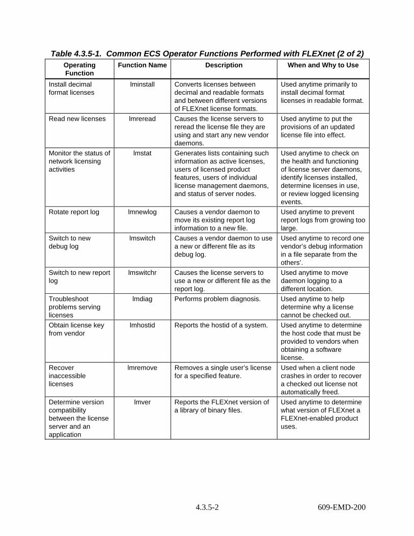
Table 4.3.5-1. Common ECS Operator Functions Performed with FLEXnet (2 of 2) Operating Function
Function Name Description When and Why to Use
Install decimal format licenses
lminstall Converts licenses between decimal and readable formats and between different versions of FLEXnet license formats.
Used anytime primarily to install decimal format licenses in readable format.
Read new licenses lmreread Causes the license servers to reread the license file they are using and start any new vendor daemons.
Used anytime to put the provisions of an updated license file into effect.
Monitor the status of network licensing activities
lmstat Generates lists containing such information as active licenses, users of licensed product features, users of individual license management daemons, and status of server nodes.
Used anytime to check on the health and functioning of license server daemons, identify licenses installed, determine licenses in use, or review logged licensing events.
Rotate report log lmnewlog Causes a vendor daemon to move its existing report log information to a new file.
Used anytime to prevent report logs from growing too large.
Switch to new debug log
lmswitch Causes a vendor daemon to use a new or different file as its debug log.
Used anytime to record one vendor’s debug information in a file separate from the others’.
Switch to new report log
lmswitchr Causes the license servers to use a new or different file as the report log.
Used anytime to move daemon logging to a different location.
Troubleshoot problems serving licenses
lmdiag Performs problem diagnosis. Used anytime to help determine why a license cannot be checked out.
Obtain license key from vendor
lmhostid Reports the hostid of a system. Used anytime to determine the host code that must be provided to vendors when obtaining a software license.
Recover inaccessible licenses
lmremove Removes a single user’s license for a specified feature.
Used when a client node crashes in order to recover a checked out license not automatically freed.
Determine version compatibility between the license server and an application
lmver Reports the FLEXnet version of a library of binary files.
Used anytime to determine what version of FLEXnet a FLEXnet-enabled product uses.
4.3.5-2 609-EMD-200

4.3.5.1 Quick Start Using FLEXnet Publisher Operators interact with FLEXnet via the license manager daemons and license files. FLEXnet’s user interface is a set of Unix-like commands for starting, stopping, and requesting services from a license manager daemon. Command arguments specify input parameters, most notably the name of the license file whose contents determine the servers, daemons, and license provisions affected by the command. Operators install and maintain license files using any preferred editor.
4.3.5.1.1 Command Line Interface To start FLEXnet license server daemons in a consistent, predictable manner, start the flexnet service:
> service flexnet start
Before it invokes FLEXnet’s “lmgrd” program, the script adds the extension “_old” to the current FLEXnet log file (if any) so the new daemon will create its own. It then runs “lmgrd” as user “flexlm” to avoid running as “root”, and it specifies the license and log file paths the daemons are to use (i.e., “/var/flexnet/license.dat” and “/tmp/license_log”, respectively).
If license manager daemons are needed to serve licenses in additional license files, they can be started by running the “lmgrd” program as follow:
> su flexlm -c "umask 022; /var/flexnet/lmgrd -c license_file -l logfile -p &"
To stop the FLEXnet license daemons that are running on all machines in the network, execute the FLEXnet command:
> /var/flexnet/lmdown –c license_file_list -all
However, to shut down the license manager daemons on a single machine only, log on to the machine and type the following command instead:
> service flexnet stop
Table 4.3.5-2 summarizes commands available with FLEXnet. See the FLEXnet Licensing End Users Guide for the complete description of each command and its arguments.
Table 4.3.5-2. Command Line Interfaces (1 of 3) Command Line
Interface Description and Format When and Why Used
lmborrow lmborrow {vendor | all} enddate [time] To use a license temporarily on a computer intermittently connected to the license server.
lmdiag lmdiag [-c license_file_list] \ [-n] [feature[:keyword=value]]
To diagnose problems when a license cannot be checked out.
lmdown lmdown [-c license_file_list] [-q] [-all] [-force
To shutdown selected license daemons (both lmgrd and selected vendor daemons) on all nodes.
4.3.5-3 609-EMD-200

Table 4.3.5-2. Command Line Interfaces (2 of 3) Command Line
Interface Description and Format When and Why Used
lmgrd lmgrd [-c license_file_list] \ [-l [+]debug_log_path] [-2 -p] [-local] \ [-x lmdown] [-x lmremove] [-z ] [-v] \ [-help]
To run the main daemon program for FLEXnet.
lmhostid lmhostid [-n] [-type] [-utf8] To determine the hostid of a system.
lminstall lminstall [-i in_lic_file ] [-maxlen n] [-e err_file] [-o out_lic_file] [-overfmt {2 | 3 | 4 | 5 | 5.1 | 6 | 7 | 7.1 | 8}] [-odecimal]
To convert licenses between decimal and readable formats and between different versions of FLEXnet formats.
lmnewlog lmnewlog [-c license_file_list] \ feature renamed_report_log or: lmnewlog [-c license_file_list] \ vendor renamed_report_log
To move an existing report log to a new file and start a new log at the original filename
lmpath lmpath {-add | -override} {vendor | all} license_file_list
To add to, override, or get the current license path settings
lmremove lmremove [-c license_file_list] feature user user_host display or lmremove [-c license_file_list] \ -h feature server_host port handle
To remove a single user's license for a specified feature. (This is only needed when a client node crashes, since that's the only condition where a license is not automatically freed. If the application is active, it checks out the license again after it is freed by lmremove.)
lmreread lmreread [-c license_file_list] \ [-vendor vendor] [-all]
To cause the license daemon to reread the license file and start any new vendor daemons that have been added. In addition, one or all pre-existing daemons are signaled to reread the license file for changes in feature licensing information.
lmswitch lmswitch [-c license_file_list] \ vendor new_debug_log
To start a new debug log for a vendor daemon, using a new filename.
lmswitchr lmswitchr [ -c license file ] feature \ new-file or lmswitchr [ -c license file ] vendor \ new-file (v5.0+ onl)
To start recording license events in a new or different log file.
4.3.5-4 609-EMD-200

Table 4.3.5-2. Command Line Interfaces (3 of 3) Command Line
Interface Description and Format When and Why Used
lmstat lmstat [-a] [-c license_file_list] \ [-f [feature]] \ [-i [feature] [-s[server][-S [vendor]] \ [-t timeout_value]
To report the status of all network licensing activities.
lmver lmver filename To identify the FLEXnet version of a library or binary file.
4.3.5.2 FLEXnet Main Screen FLEXnet does not provide for operator interaction via a GUI. All interactions are through the Unix command line or a Unix script.
4.3.5.3 Required Operating Environment For all COTS packages, appropriate information on operating environments, tunable parameters, environment variables, and a list of vendor documentation can be found in a CM-controlled document for each product. To find the installation and release notes for FLEXnet Publisher, refer to the Release Notes posted on the EMD Baseline Information System web page at your local site.
4.3.5.4 Databases FLEXnet uses license and options files in lieu of a database. License files are independent text files, each of which contains all the site-specific information FLEXnet needs to serve the licenses specified in the file. Every license manager daemon requires a license file, and different license files require separate license manager daemons. To simplify operations, operators may combine license files obtained from multiple vendors if they are compatible. Refer to the FLEXnet Licensing End User Guide for information about the format of a license file, and when and how to combine them.
Options files are text files associated with specific vendor daemons named in license files. These files allow the operator to specify criteria for granting licenses to users, wait time before reclaiming inactive licenses, and how much license usage information is to be logged. FLEXnet does not require an options file. When specified however, there can only be one options file per vendor daemon, and each vendor needs a separate options file. See the FLEXnet Licensing End User Guide for details.
4.3.5.5 Special Constraints FLEXnet cannot be run without one or more license files, and most FLEXnet commands require the name of a license file in order to execute. License files identify the host and port number a client is to use to communicate with the license server. If the license file parameter is missing from the command, FLEXnet tries using the file(s) named in the environment variable LM_LICENSE_FILE. If LM_LICENSE_FILE is not set, the default license file name /var/flexnet/license.dat is assumed.
4.3.5-5 609-EMD-200
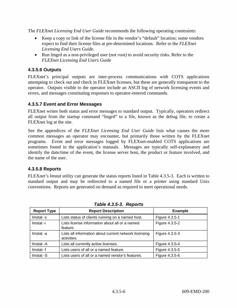
The FLEXnet Licensing End User Guide recommends the following operating constraints: • Keep a copy or link of the license file in the vendor’s “default” location; some vendors
expect to find their license files at pre-determined locations. Refer to the FLEXnet Licensing End Users Guide.
• Run lmgrd as a non-privileged user (not root) to avoid security risks. Refer to the FLEXnet Licensing End Users Guide
4.3.5.6 Outputs FLEXnet’s principal outputs are inter-process communications with COTS applications attempting to check out and check in FLEXnet licenses, but these are generally transparent to the operator. Outputs visible to the operator include an ASCII log of network licensing events and errors, and messages constituting responses to operator-entered commands.
4.3.5.7 Event and Error Messages FLEXnet writes both status and error messages to standard output. Typically, operators redirect all output from the startup command “lmgrd” to a file, known as the debug file, to create a FLEXnet log at the site.
See the appendices of the FLEXnet Licensing End User Guide lists what causes the more common messages an operator may encounter, but primarily those written by the FLEXnet programs. Event and error messages logged by FLEXnet-enabled COTS applications are sometimes found in the application’s manuals. Messages are typically self-explanatory and identify the date/time of the event, the license server host, the product or feature involved, and the name of the user.
4.3.5.8 Reports FLEXnet’s lmstat utility can generate the status reports listed in Table 4.3.5-3. Each is written to standard output and may be redirected to a named file or a printer using standard Unix conventions. Reports are generated on demand as required to meet operational needs.
Table 4.3.5-3. Reports Report Type Report Description Example
lmstat -s Lists status of clients running on a named host. Figure 4.3.5-1 lmstat -i Lists license information about all or a named
feature. Figure 4.3.5-2
lmstat -a Lists all information about current network licensing activities.
Figure 4.3.5-3
lmstat -A Lists all currently active licenses. Figure 4.3.5-4 lmstat -f Lists users of all or a named feature. Figure 4.3.5-5 lmstat -S Lists users of all or a named vendor’s features. Figure 4.3.5-6
4.3.5-6 609-EMD-200
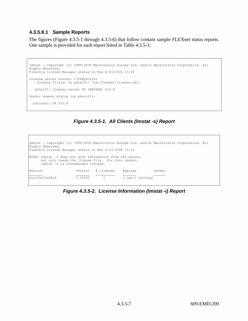
4.3.5.8.1 Sample Reports The figures (Figure 4.3.5-1 through 4.3.5-6) that follow contain sample FLEXnet status reports. One sample is provided for each report listed in Table 4.3.5-3.
lmstat - Copyright (c) 1989-2006 Macrovision Europe Ltd. and/or Macrovision Corporation. All Rights Reserved. Flexible License Manager status on Mon 6/23/2008 13:18 License server status: 1726@p4nsl01 License file(s) on p4nsl01: /var/flexnet/license.dat: p4nsl01: license server UP (MASTER) v10.8 Vendor daemon status (on p4nsl01): rational: UP v10.8
Figure 4.3.5-1. All Clients (lmstat -s) Report
lmstat - Copyright (c) 1989-2006 Macrovision Europe Ltd. and/or Macrovision Corporation. All Rights Reserved. Flexible License Manager status on Mon 6/23/2008 13:16 NOTE: lmstat -i does not give information from the server, but only reads the license file. For this reason, lmstat -a is recommended instead. Feature Version # licenses Expires Vendor _______ _______ __________ _______ ______ PurifyPlusUNIX 5.00000 1 1-jan-0 rational
Figure 4.3.5-2. License Information (lmstat -i) Report
4.3.5-7 609-EMD-200

lmstat - Copyright (c) 1989-2006 Macrovision Europe Ltd. and/or Macrovision Corporation. All Rights Reserved. Flexible License Manager status on Mon 6/23/2008 13:19 License server status: 1726@p4nsl01 License file(s) on p4nsl01: /var/flexnet/license.dat: p4nsl01: license server UP (MASTER) v10.8 Vendor daemon status (on p4nsl01): rational: UP v10.8 Feature usage info: Users of PurifyPlusUNIX: (Total of 1 license issued; Total of 0 licenses in use)
Figure 4.3.5-3. All Licensing Activities (lmstat -a) Report
lmstat - Copyright (c) 1989-2006 Macrovision Europe Ltd. and/or Macrovision Corporation. All Rights Reserved. Flexible License Manager status on Mon 6/23/2008 13:20 License server status: 1726@p4nsl01 License file(s) on p4nsl01: /var/flexnet/license.dat: p4nsl01: license server UP (MASTER) v10.8 Vendor daemon status (on p4nsl01): rational: UP v10.8 Feature usage info:
Figure 4.3.5-4. All Active Licenses (lmstat-A) Report
4.3.5-8 609-EMD-200

lmstat - Copyright (c) 1989-2006 Macrovision Europe Ltd. and/or Macrovision Corporation. All Rights Reserved. Flexible License Manager status on Mon 6/23/2008 13:21 License server status: 1726@p4nsl01 License file(s) on p4nsl01: /var/flexnet/license.dat: p4nsl01: license server UP (MASTER) v10.8 Vendor daemon status (on p4nsl01): rational: UP v10.8 Feature usage info: Users of PurifyPlusUNIX: (Total of 1 license issued; Total of 0 licenses in use)
Figure 4.3.5-5. Users of All or Named Features (lmstat-f) Report
lmstat - Copyright (c) 1989-2006 Macrovision Europe Ltd. and/or Macrovision Corporation. All Rights Reserved. Flexible License Manager status on Mon 6/23/2008 13:24 Feature usage info: Users of PurifyPlusUNIX: (Total of 1 license issued; Total of 0 licenses in use)
Figure 4.3.5-6. Users of All or Named Vendor’s Features (lmstat-S) Report
4.3.5-9 609-EMD-200

This page intentionally left blank.
4.3.5-10 609-EMD-200

4.3.6 TestTrack Pro TestTrack Pro (TTPro) provides a Trouble Ticketing service that furnishes both ECS users and operations personnel at the DAACs a common environment for classifying, tracking, and reporting the occurrence and resolution of system-related problems. The Trouble Ticketing Service:
• Provides a GUI for operations personnel to access all Trouble Ticket functions • Provides a common Trouble Ticket entry format • Stores Trouble Tickets • Retrieves Trouble Tickets via ad-hoc queries • Allows operations personnel to escalate problems to the EDF for review and resolution • Generates reports and statistics • Interfaces with user’s and operator’s e-mail to provide automatic notification • Offers an application programming interface, Simple Object Access Protocol (SOAP)
Software Development Kit (SDK), through which applications can submit and manage Trouble Tickets
• Generates a variety of reports about Trouble Tickets, including trend reports • Defines a consistent “life-cycle” for Trouble Tickets • Can be extended readily due to its highly customizable fields, workflow rules, system
notifications, and user permissions. TTPro gives ECS operators, technicians, and managers the means to manage a system defect through its lifecycle, whether as a Trouble Ticket at a DAAC or a non-conformance report at the EDF. Within TTPro a separate project (also known as a “database”) exists for each ECS site’s Trouble Tickets.
TTPro has a client/server architecture. The server is hosted on a Linux machine at the EDF, while client access is available locally or remotely via Windows-, Linux-,Solaris, and Web-based clients.
User Services and other operations and support personnel use TTPro to perform the functions listed in Table 4.3.6-1. The sections that follow describe the GUIs that perform these functions, many of which include customizations made for ECS. Standard product features are mentioned but not discussed in detail. For more information about them, use the context sensitive help the tool provides, or refer to the following TestTrack vendor documents:
• Getting Started with TestTrack • TestTrack User Guide Version 2008 • TestTrack Web User Guide, Version 2008 • Seapine License Server Admin Guide, Version 2008
4.3.6-1 609-EMD-200

Table 4.3.6-1. Common ECS Operator Functions Performed using TestTrack Pro (1 of 3)
Operating Function
GUI (Section) Description When and Why to Use
Access defect tracking services
Login screens (4.3.6.1.1)???
• Operators start their client of choice and use the Login screens to access a TTpro project. The Login screen is the gateway to TestTrack Pro’s features. By default, users land on the Trouble Ticket list screen from where all other functions can be performed.
When there is a need to submit, query, or revise a Trouble Ticket
Submit a Trouble Ticket
Add Trouble Ticket screen (4.3.6.2.2)
• Operators add a new Trouble Ticket to the system.
• Trouble Ticket form is used to enter information about the problem
When a problem is either found by or reported to User Services.
Browse Trouble Tickets
Edit Trouble Ticket screen (4.3.6.2.3)
• Operators review existing Trouble Tickets.
• Allows entry of new information about the problem and recording of events that advance the defect report through its lifecycle states.
When information needs to be added to a Trouble Ticket or when a Trouble Ticket needs to be viewed.
Escalate a Trouble Ticket to the EDF
Escalate screen (4.3.6.2.4.5)
• Operators raise an Escalate event that forwards a specified Trouble Ticket to the EDF.
• A script uses TTPro’s SOAP API to create a defect report in the Operations_NCRs project automatically using information from the Trouble Ticket.
• Notifications are sent to the EDF and the ticket owner that a ticket has been escalated.
When assistance in resolving the Trouble Ticket is needed from the EDF or the problem requires a hardware or software change.
4.3.6-2 609-EMD-200

Table 4.3.6-1. Common ECS Operator Functions Performed using TestTrack Pro (2 of 3)
Operating Function
GUI (Section) Description When and Why to Use
Generate reports Reports screen (4.3.6.2.5)
• Operators run or create new reports. The screen is accessed from the Trouble Ticket list screen. Reports can be viewed, created, edited, deleted, printed, or previewed by selecting the appropriate button on the Reports screen.
When information is needed about one or more Trouble Tickets
Add, delete, or modify user accounts
License Server Admin tool’s Global Users screen (4.3.6.2.13) TTPro Client Edit Users screen (4.3.6.2.8)
• TTPro administrators add, delete, and modify user profiles, including user IDs and passwords.
• TTPro administrators assign operators and users to a security groups on a project-by-project basis. Each project’s security groups enforce what the operator or user can do in that project.
When there is a need to update: 1) the list of operators and users authorized to access each project; 2) what features and records an operator or user can access; 3) contact information and/or passwords; and. 4) reset individual passwords.
Customize pulldown menus
Setup <field> Names screens (4.3.6.2.9-4.3.6.2.11)
• TTPro administrators add, edit, reorder, and delete values used in TTPro’s field pulldown menus. This ensures that data is entered uniformly in fields used for categorizing defects.
When current menus require updating.
4.3.6-3 609-EMD-200

Table 4.3.6-1. Common ECS Operator Functions Performed using TestTrack Pro (3 of 3)
Operating Function
GUI (Section) Description When and Why to Use
Issue Notifications Configure Automation Rules screen Edit Trouble Ticket screens User Options screen (4.3.6.2.10 & 4.3.6.2.11)
• TTPro administrators configure rules used by TTPro for issuing system notifications to individual operators and users. System notifications are used primarily to alert defect report assignees, submitters, etc. when their defect report or its status has changed.
• Operators and users designate particular individuals to receive an e-mail whenever a Trouble Ticket or NCR has changed.
• Operators and users define personal rules the system uses to e-mail them about changes to defect reports they are authorized to see.
To inform someone via e-mail when a Trouble Ticket or NCR changes in one or more of a variety of ways.
4.3.6.1 Quick Start Using TestTrack Pro This section describes how to invoke TTPro. For more information, use the context sensitive help the tool provides, or refer to the following vendor documents:
• Getting Started • TestTrack User Guide • TestTrack Web User Guide
4.3.6.1.1 Invoking TestTrack Pro Each of the three TTPro clients are started differently.
To start the Windows client on Windows XP:
Click Start All Programs Seapine Sofware TestTrack 2008 TestTrack Client on your desktop.
To start the Linux or Solaris client, enter:
/usr/ecs/OPS/COTS/ttpro/bin/ttclient &
4.3.6-4 609-EMD-200

To start the Web client, open a browser and enter the following URL:
https://links.gsfc.nasa.gov:<port>
Under Windows, Linux, and Solaris, a Login GUI similar to that in Figure 4.3.6-1 will appear. (See section 4.3.6.2.14. for a discussion of the the Web login screen.)
Select the TestTrack Server you want to access, and enter your TTPro Username (i.e., login ID) and password. Since the URL for the Web client already specifies the server to use, its Login GUI requests only the Username and Password.
Figure 4.3.6-1. TestTrack Studio Login GUI
Table 4.3.6-2 provides a description of the Login screen’s field.
Table 4.3.6-2. TestTrack Studio Login Field Descriptions Field Name Data Type Size Entry Description
Server Selection * Required Your name for this TTPro server connection
Username Selection * Required User’s TTPro login id Password Selection * Required User’s TTPro password
*Note: the size of a field with a "selection" data type can vary and the size is automatically adjusted to the size of the item selected from the selection list.
The Login screen has the following buttons:
• Setup… Opens the Edit TestTrack Pro Server GUI for defining server connections • Connect Submits user’s credentials to determine which projects the user can access • Cancel Closes the screen and ends the login sequence.
4.3.6-5 609-EMD-200

If using TTPro for the first time, the Add TestTrack Server GUI will appear so you can define a TTPro server connection. (See Figure 4.3.6-2) Your TTPro administrator can help you set up the connection.
Figure 4.3.6-2. Add TestTrack Server GUI
Table 4.3.6-3 provides a description of the Add TestTrack Server screen’s fields.
Table 4.3.6-3. Add TestTrack Server Field Descriptions Field Name Data Type Size Entry Description
Server Name Character > 200 Required Name of TTPro server connection Server Address Character > 200 Required Fully qualified domain name of the
TTPro server Port Integer 5 Required Port on which TTPro clients
communicate with the TTPro server
The TestTrack Project Selection screen has the following buttons:
• OK Adds the new server definition to the user’s configuration • Cancel Closes the screen without accepting entered data.
4.3.6-6 609-EMD-200

Upon username and password verification, the TestTrack Project Selection GUI appears (Figure 4.3.6-3). Use this screen to specify which project to log in to. The Project picklist displays only the projects to which the user has access. If the picklist is empty or indicates that projects are loading, click Refresh after a few moments to retrieve a new list. You can set the Always login to this project checkbox to use this project as your default in the future.
Figure 4.3.6-3. TestTrack Project Selection GUI
Table 4.3.6-4 provides a description of the TestTrack Project Selection screen’s fields.
Table 4.3.6-4. TestTrack Project Selection Field Descriptions Field Name Data Type Size Entry Description
Project Selection * Required Name of the project to logon to. Lists only the projects the user is authorized to access.
*Note: the size of a field with a "selection" data type can vary and the size is automatically adjusted to the size of the item selected from the selection list.
The TestTrack Project Selection screen has the following buttons:
• Refresh Retrieves the latest list of available TestTrack projects the user is authorized to access
• OK Logs the user into the selected project • Cancel Cancels the logon request.
The sections that follow describe the screens displayed by the Windows and Linux clients. The Web Client provides the same functionality and fields, but the displays and user interactions are necessarily somewhat different.
4.3.6-7 609-EMD-200

4.3.6.2 Main Screen TTPro’s main screen is shown in Figure 4.3.6-4. From here Trouble Tickets can be submitted, queried, modified, and escalated. The GUI can manage multiple windows concurrently, and it offers a menu bar and a complement of movable toolbars for easily navigating system screens.
Figure 4.3.6-4. Main GUI
4.3.6.2.1 Trouble Ticket List Screen Operators and users use the Trouble Ticket List screen (see Figure 4.3.6-5) to browse, select, and open one or more Trouble Tickets. Use the Filter pull down menu to retrieve the records you want. Initiate action on a Trouble Ticket by clicking on a row then on one of the action buttons. Initiate action on multiple records by dragging your mouse over several rows before pressing the action button.
The screen can be configured to display data as you prefer. Insert or remove columns of data by right-clicking on the column heading. Adjust the width of a column by dragging the bar in the column heading that separates it from its neighbor, or double-click on the bar to size it
4.3.6-8 609-EMD-200
automatically. Sort the data by clicking on a column heading; add a secondary sort by holding the Shift key and clicking on a second column heading.
Important: Exit the screen by selecting File Logout & Disconnect from the TTPro menu bar. On the Web client, use the Logout hyperlink. Otherwise, the system may not release the license immediately.
Figure 4.3.6-5. Trouble Tickets List GUI
Table 4.3.6-5 provides a description of the Trouble Ticket List screen’s field.
Table 4.3.6-5. Trouble Tickets List Field Descriptions Field Name Data Type Size Entry Description
Address String n/a Optional TTPro address for the current list window or open item. Can display ttstudio or http addresses
Filter Selection * Optional Name for the set of criteria to be used by the system to determine which Trouble Tickets to display
Find String Optional Value to search for In Selection * Optional Field in which to search for the value
4.3.6-9 609-EMD-200

*Note: the size of a field with a "selection" data type can vary and the size is automatically adjusted to the size of the item selected from the selection list.
The Trouble Tickets List screen has the following buttons:
• View… Opens a Trouble Ticket for viewing only. • Add… Opens the Add Trouble Ticket screen for submitting a new Trouble
Ticket. • Edit… Opens a Trouble Ticket for modification. • Delete Removes a Trouble Ticket from the database • Find Initiates a search for records that meet the criteria specified by values in
the Find and In fields • Options Opens a menu of advanced conditions for tailoring a record search
4.3.6.2.2 Add Trouble Ticket Screen The Add Trouble Ticket screen (Figures 4.3.6-6 thru 4.3.6-8) is used for reporting an operational issue or problem in ECS. Depending on how a user’s options are configured, the screen will display in either vertical tab (Figure 4.3.6-6) or single page (Figures 4.3.6-7 thru 4.3.6-8) format. Clicking Add on this screen creates the Trouble Ticket and commits the data to the database.
Figure 4.3.6-6. Add Trouble Ticket GUI – Vertical Tab View
4.3.6-10 609-EMD-200
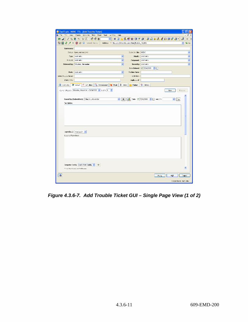
Figure 4.3.6-7. Add Trouble Ticket GUI – Single Page View (1 of 2)
4.3.6-11 609-EMD-200

Figure 4.3.6-8. Add Trouble Ticket GUI – Single Page View (2 of 2)
Table 4.3.6-6 provides a description of the Add Trouble Ticket screen’s fields.
Table 4.3.6-6. Add Trouble Ticket Field Descriptions (1 of 2) Field Name Data Type Size Entry Description
Summary Character 154 Required Short Description of the problem. Status Character n/a System
generated Status of the Trouble Ticket (a combination of state and assignment status)
Submitter Site Selection * Optional Trouble ticket’s originating site
4.3.6-12 609-EMD-200
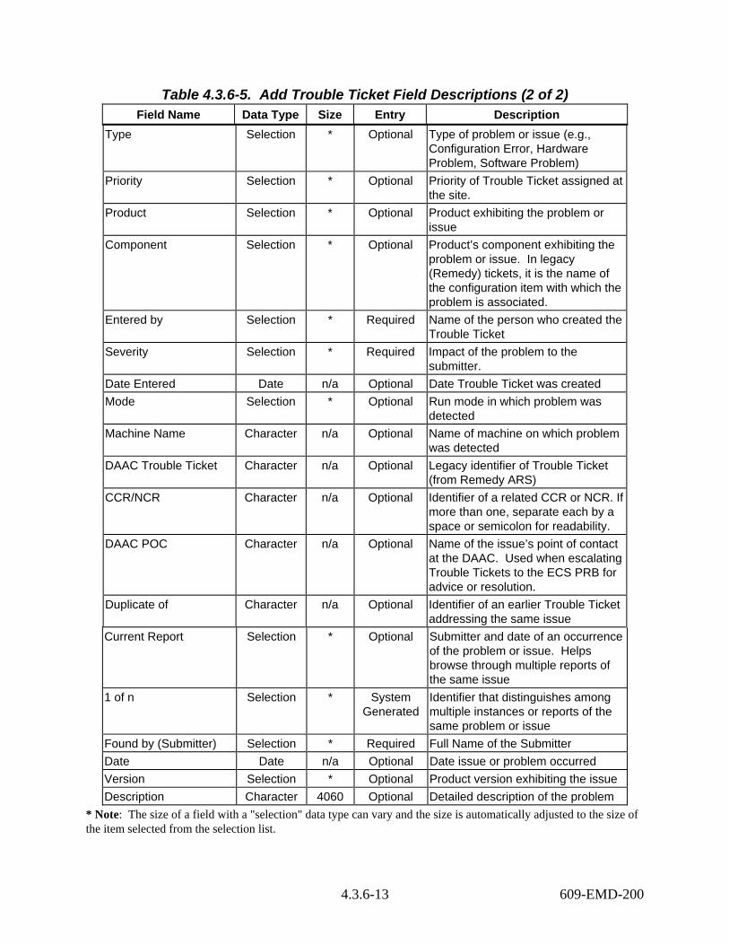
Table 4.3.6-5. Add Trouble Ticket Field Descriptions (2 of 2) Field Name Data Type Size Entry Description
Type Selection * Optional Type of problem or issue (e.g., Configuration Error, Hardware Problem, Software Problem)
Priority Selection * Optional Priority of Trouble Ticket assigned at the site.
Product Selection * Optional Product exhibiting the problem or issue
Component Selection * Optional Product’s component exhibiting the problem or issue. In legacy (Remedy) tickets, it is the name of the configuration item with which the problem is associated.
Entered by Selection * Required Name of the person who created the Trouble Ticket
Severity Selection * Required Impact of the problem to the submitter.
Date Entered Date n/a Optional Date Trouble Ticket was created Mode Selection * Optional Run mode in which problem was
detected Machine Name Character n/a Optional Name of machine on which problem
was detected DAAC Trouble Ticket Character n/a Optional Legacy identifier of Trouble Ticket
(from Remedy ARS) CCR/NCR Character n/a Optional Identifier of a related CCR or NCR. If
more than one, separate each by a space or semicolon for readability.
DAAC POC Character n/a Optional Name of the issue’s point of contact at the DAAC. Used when escalating Trouble Tickets to the ECS PRB for advice or resolution.
Duplicate of Character n/a Optional Identifier of an earlier Trouble Ticket addressing the same issue
Current Report Selection * Optional Submitter and date of an occurrence of the problem or issue. Helps browse through multiple reports of the same issue
1 of n Selection * System Generated
Identifier that distinguishes among multiple instances or reports of the same problem or issue
Found by (Submitter) Selection * Required Full Name of the Submitter Date Date n/a Optional Date issue or problem occurred Version Selection * Optional Product version exhibiting the issue Description Character 4060 Optional Detailed description of the problem
* Note: The size of a field with a "selection" data type can vary and the size is automatically adjusted to the size of the item selected from the selection list.
4.3.6-13 609-EMD-200

The Add Trouble Ticket screen has the following buttons:
• New Adds another Found By record to the trouble ticket • Remove Removes the displayed Found By record from the trouble ticket • Edit User (eye icon) Opens the Found By user’s profile record for editing • Find Customer (customer icon) Opens a menu of advanced conditions for tailoring
a record search • Printer Generates a detail report of the open item • Apply Opens a Trouble Ticket for viewing only • Add… Saves the trouble ticket and adds it to the project • Cancel Exits the screen without saving data
4.3.6.2.3 Edit Trouble Ticket Screen The Edit Trouble Ticket (Figure 4.3.6-9) screen is used to update an existing Trouble Ticket and advance it through its lifecycle states. The latter is done by selecting an appropriate item on the Activities menu or clicking the appropriate Activities icon (in this view, the second row of icons on the toolbar), either of which opens an Activity screen (see Section 4.3.6.2.4).
Figure 4.3.6-9. Edit Trouble Ticket GUI
4.3.6-14 609-EMD-200

The Edit Trouble Ticket screen’s fields are the same as those for the Add Trouble Ticket screen. See Table 4.3.6-6 above..
This screen has four buttons that differ from those on the Add Trouble Ticket screen:
• Left arrow Commits changes to the database and displays the previous Trouble Ticket in the Trouble Ticket list • Right arrow Commits changes to the database and displays the next Trouble Ticket in
the Trouble Ticket list • Send Email… Opens a screen for composing and sending email to one or more TTPro
users. Senders can use an email template to include data about the open trouble ticket.
• OK Commits changes to the database
4.3.6.2.4 Activity Screens The screens in this section advance Trouble Tickets through their lifecycle states.
Each activity screen has the following buttons:
• OK Accepts entered data and closes the screen • Cancel Closes the screen without accepting entered data.
Important: Clicking OK does not update the database. The database is updated only when subsequently closing the calling Add Trouble Ticket or Edit Trouble Ticket screens.
4.3.6.2.4.1 Assign Screen The Assign screen (Figure 4.3.6-10) is used for recording that a staff member has been assigned to work on the issue described by the Trouble Ticket.
Figure 4.3.6-10. Assign GUI
Table 4.3.6-7 provides a description of the Assign screen’s fields.
4.3.6-15 609-EMD-200

Table 4.3.6-7. Assign Field Descriptions Field Name Data Type Size Entry Description
Assign By Selection * Required Who is making the assignment
Date Date/Time n/a Required Date assignment is made
Assign To Selection * Optional Name of the assignee
Notes Text Optional Message for the assignee *Note: The size of a field with a "selection" data type can vary and the size is automatically adjusted to the size of the item selected from the selection list.
4.3.6.2.4.2 Propose Solution Screen The Propose Solution screen (Figure 4.3.6-11) is used for documenting how to resolve the issue described by the Trouble Ticket. Clicking OK on this screen advances the Trouble Ticket to the Solution Proposed state.
Figure 4.3.6-11. Propose Solution GUI
Table 4.3.6-8 provides a description of the Propose Solution screen’s fields.
Table 4.3.6-8. Propose Solution Field Descriptions Field Name Data Type Size Entry Description
Propose Solution By Selection * Required Who is proposing the solution Date Date/Time n/a Required Date solution is proposed Notes Text n/a Optional The proposed solution
*Note: the size of a field with a "selection" data type can vary and the size is automatically adjusted to the size of the item selected from the selection list.
4.3.6.2.4.3 Start to Implement Screen The Start to Implement screen (Figure 4.3.6-12) is used for documenting work towards implementing the solution to the problem described in the Trouble Ticket. Clicking OK on this screen advances the TroubleTticket to the Start to Implement state.
4.3.6-16 609-EMD-200

Figure 4.3.6-12. Start to Implement GUI
Table 4.3.6-9 provides a description of the Start to Implement screen’s fields.
Table 4.3.6-9. Start to Implement Field Descriptions Field Name Data Type Size Entry Description
Implement By Selection * Required Who is implementing the solution Date Date/Time n/a Required Date work started towards a solution Notes Text n/a Optional Details on progress towards solution
*Note: the size of a field with a "selection" data type can vary and the size is automatically adjusted to the size of the item selected from the selection list.
4.3.6.2.4.4 Fix Screen The Fix screen (Figure 4.3.6-13) is used for reporting that the issue described in the Trouble Ticket has been solved. Clicking OK on this screen advances the Trouble Ticket to the Fixed state.
Figure 4.3.6-13. Fix GUI
Table 4.3.6-10 provides a description of the Fix screen’s fields.
4.3.6-17 609-EMD-200

Table 4.3.6-10. Fix Field Descriptions Field Name Data Type Size Entry Description
Fixed By Selection * Required Who fixed the problem Date Date/Time n/a Required Date solution was implemented Effort Decimal Optional Hours it took to resolve the issue Notes Text Optional Details of how the issue was resolvedAffects Documentation Check box n/a Optional Is a documentation change req’d? Affects Test Plan Check box n/a Optional Is a test plan change req’d? Resolution Selection * Required Type of resolution Version Selection * Optional Product version first containing fix
*Note: the size of a field with a "selection" data type can vary and the size is automatically adjusted to the size of the item selected from the selection list.
4.3.6.2.4.5 Escalate Screen The Escalate screen (Figure 4.3.6.14) is used for forwarding an issue to the the ECS Problem Review Board (PRB) for advice or resolution. Clicking OK on this screen advances the Trouble Ticket to the Forwarded state.
Note: A cron job runs periodically to extract the data from escalated Trouble Tickets in order to create corresponding ECS non-conformance reports (NCRs).
Figure 4.3.6-14. Escalate GUI
Table 4.3.6-11 provides a description of the Escalate screen’s fields.
Table 4.3.6-11. Escalate Field Descriptions (1 of 2) Field Name Data Type Size Entry Description
Escalate By Selection * Required Who is escalating the problem Date Date/Time n/a Required Date Trouble Ticket is escalated Notes Text Optional Details of how the issue was resolvedEscalate To Selection * Required Name of target NCR project
4.3.6-18 609-EMD-200
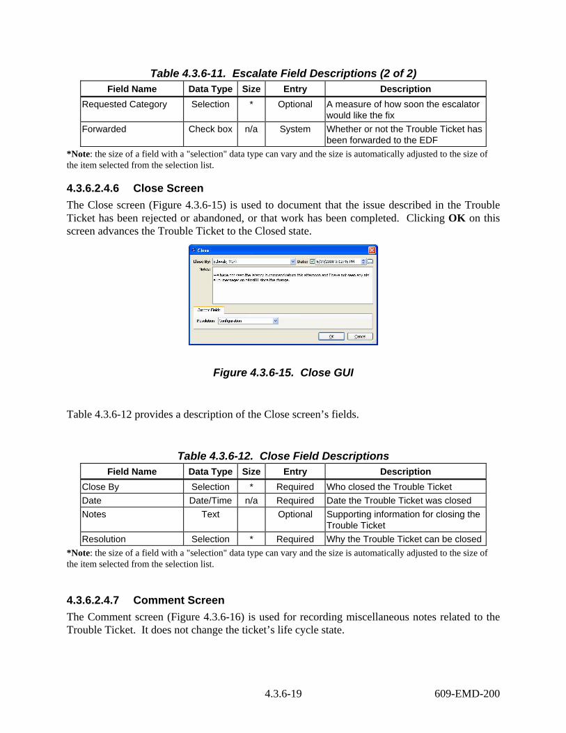
Table 4.3.6-11. Escalate Field Descriptions (2 of 2) Field Name Data Type Size Entry Description
Requested Category Selection * Optional A measure of how soon the escalator would like the fix
Forwarded Check box n/a System Whether or not the Trouble Ticket has been forwarded to the EDF
*Note: the size of a field with a "selection" data type can vary and the size is automatically adjusted to the size of the item selected from the selection list.
4.3.6.2.4.6 Close Screen The Close screen (Figure 4.3.6-15) is used to document that the issue described in the Trouble Ticket has been rejected or abandoned, or that work has been completed. Clicking OK on this screen advances the Trouble Ticket to the Closed state.
Figure 4.3.6-15. Close GUI
Table 4.3.6-12 provides a description of the Close screen’s fields.
Table 4.3.6-12. Close Field Descriptions Field Name Data Type Size Entry Description
Close By Selection * Required Who closed the Trouble Ticket Date Date/Time n/a Required Date the Trouble Ticket was closed Notes Text Optional Supporting information for closing the
Trouble Ticket Resolution Selection * Required Why the Trouble Ticket can be closed
*Note: the size of a field with a "selection" data type can vary and the size is automatically adjusted to the size of the item selected from the selection list.
4.3.6.2.4.7 Comment Screen The Comment screen (Figure 4.3.6-16) is used for recording miscellaneous notes related to the Trouble Ticket. It does not change the ticket’s life cycle state.
4.3.6-19 609-EMD-200

Figure 4.3.6-16. Comment GUI
Table 4.3.6-13 provides a description of the Comment screen’s fields.
Table 4.3.6-13. Comment Field Descriptions Field Name Data Type Size Entry Description
Comment By Selection * Required Who is recording the comment Date Date/Time n/a Required Date the comment is recorded Notes Text Optional The comment
*Note: the size of a field with a "selection" data type can vary and the size is automatically adjusted to the size of the item selected from the selection list.
4.3.6.2.5 Reports Screen The Reports screen (Figure 4.3.6-17) is used for generating pre-defined and ad hoc Trouble Ticket reports. Four types of reports are possible: list, detail, trend, and distribution. (See Section 4.3.6.8.1 for an example of each.) TTPro uses style sheets as templates for generating reports.
The TestTrack User Guide and the TestTrack Web User Guide provide details about the subordinate screens used to define new reports, including how to specify or edit stylesheets, page breaks, sort columns, timeframes, totals, and charts.
4.3.6-20 609-EMD-200

Figure 4.3.6-17. Reports GUI
The Reports screen has the following buttons:
• View… Opens a screen for viewing the configuration of the report. • Add… Opens a screen for defining a new report. • Edit… Opens a screen for editing the configuration of a pre-defined report. • Delete Deletes an operator-selected report. • Print Runs the report, directing output to a selected printer (Windows client
only) • Preview Runs the report and presents it via the user’s default web browser
The Print Options screen (Figure 4.3.6-18) provides another means of printing adhoc reports containing one or more items from any TTPro list window, including trouble tickets. This screen is invoked by selecting items to print and then clicking File Print… on TTPro’s menu bar.
Figure 4.3.6-18. Print Options GUI
4.3.6-21 609-EMD-200
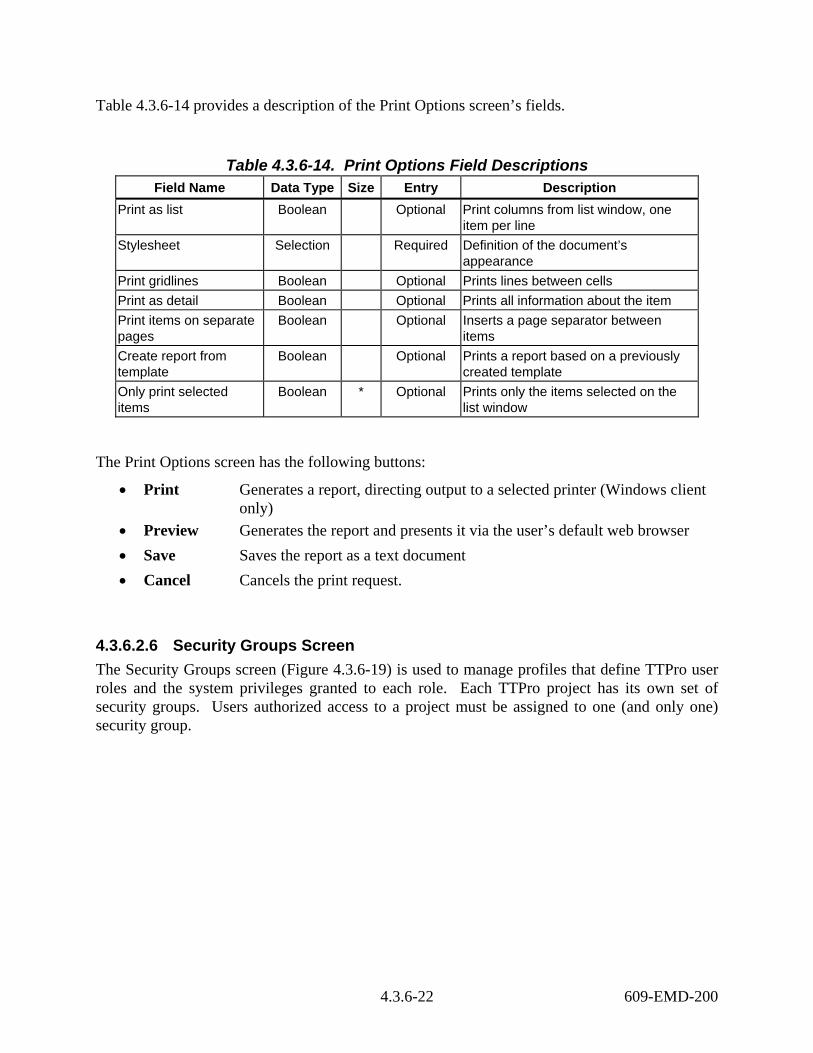
Table 4.3.6-14 provides a description of the Print Options screen’s fields.
Table 4.3.6-14. Print Options Field Descriptions Field Name Data Type Size Entry Description
Print as list Boolean Optional Print columns from list window, one item per line
Stylesheet Selection Required Definition of the document’s appearance
Print gridlines Boolean Optional Prints lines between cells Print as detail Boolean Optional Prints all information about the item Print items on separate pages
Boolean Optional Inserts a page separator between items
Create report from template
Boolean Optional Prints a report based on a previously created template
Only print selected items
Boolean * Optional Prints only the items selected on the list window
The Print Options screen has the following buttons:
• Print Generates a report, directing output to a selected printer (Windows client only)
• Preview Generates the report and presents it via the user’s default web browser • Save Saves the report as a text document • Cancel Cancels the print request.
4.3.6.2.6 Security Groups Screen The Security Groups screen (Figure 4.3.6-19) is used to manage profiles that define TTPro user roles and the system privileges granted to each role. Each TTPro project has its own set of security groups. Users authorized access to a project must be assigned to one (and only one) security group.
4.3.6-22 609-EMD-200

Figure 4.3.6-19. Security Groups GUI
This screen has no data entry fields other than Address described earlier in Table 4.3.6-5.
The Security Groups screen has the following buttons:
• View… Opens a screen for viewing selected groups’ privileges within the project. • Add… Opens a screen for adding a new group and its privileges to the project • Edit… Opens a screen for updating selected groups’ privileges within the project Delete Deletes selected security groups. Users who were members of the deleted group(s) are no longer assigned to any project. They cannot access the project nor can they receive project-issued e-mail notifications.
See the TestTrack manuals for descriptions of the Add Security Group, Edit Security Group, and View Security Group screens.
4.3.6.2.7 Users Screen The Users screen (Figure 4.3.6-20) is used to manage profiles that define who can access the project’s Trouble Tickets. Double-clicking on one or more users in the list opens either the View User or Edit User screens, depending on the client’s user options settings.
Profiles can be global or local. Global user profiles can be shared among all TTPro projects on the network. Local user profiles are known only within the project in which they are defined, but they can be promoted to a global user profile if the user’s name is unique among all projects.
4.3.6-23 609-EMD-200

Figure 4.3.6-20. Users GUI
This screen has no data entry fields other than Address described earlier in Table 4.3.6-5.
The Users screen has the following buttons:
• View… Opens a screen for viewing selected users’ profiles within the project. • Add… Opens a screen for adding a new user profile to the project • Edit… Opens a screen for updating selected user profiles within the project • Delete Deletes selected user profiles. Deleting a user removes all references to
hat user from the project’s Trouble Tickets. • Retrieve Global User Adds a user to the project by retrieving the user’s
profile from the TTPro license server’s global user records.
• Promote Adds selected, local user profiles to the TTPro license server’s global user database.
See the TestTrack manuals for descriptions of the Add User and View User screens. The Edit User screen is described in the next section.
4.3.6.2.8 Edit User Screen Use the Edit User screen (Figure 4.3.6-21) to update user profiles for the project. Its fields are identical to those of the Add User and View User screens.
4.3.6-24 609-EMD-200

Figure 4.3.6-21. Edit User GUI
Table 4.3.6-15 provides a description of the Edit User screen’s fields (Info tab only).
Table 4.3.6-15. Edit User Field Descriptions (Info Tab only) Field Name Data Type Size Entry Description
First Name Character 32 Optional User’s first name. (Optional only if a last name is specified.)
MI Character 8 Optional Last Name Character 32 Optional User’s surname. (Optional only if a
first name is specified.) Username Character 32 Optional User’s logon IDr Security Group Selection * Required User’s assigned security group Phone Number (Type) Selection * Optional User’s phone type (work, home, fax,
pager, mobile) Phone Number (Type) Selection * Optional User’s phone type (work, home, fax,
pager, mobile) Email Address (Type) Character 32 Optional User’s email type (Internet, MAPI,
other). Email Address Character 32 Optional User’s e-mail address to use for
notifications Password Character n/a Optional User’s Password Confirm Password Character n/a Optional User’s Password
*Note: The size of a field with a "selection" data type can vary and the size is automatically adjusted to the size of the item selected from the selection list.
4.3.6-25 609-EMD-200
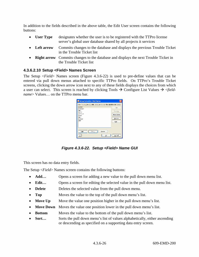
In addition to the fields described in the above table, the Edit User screen contains the following buttons:
• User Type designates whether the user is to be registered with the TTPro license server’s global user database shared by all projects it services
• Left arrow Commits changes to the database and displays the previous Trouble Ticket in the Trouble Ticket list • Right arrow Commits changes to the database and displays the next Trouble Ticket in
the Trouble Ticket list
4.3.6.2.10 Setup <Field> Names Screen The Setup <Field> Names screen (Figure 4.3.6-22) is used to pre-define values that can be entered via pull down menus attached to specific TTPro fields. On TTPro’s Trouble Ticket screens, clicking the down arrow icon next to any of these fields displays the choices from which a user can select. This screen is reached by clicking Tools Configure List Values <field-name> Values… on the TTPro menu bar.
Figure 4.3.6-22. Setup <Field> Name GUI
This screen has no data entry fields.
The Setup <Field> Names screen contains the following buttons:
• Add… Opens a screen for adding a new value to the pull down menu list. • Edit… Opens a screen for editing the selected value in the pull down menu list. • Delete Deletes the selected value from the pull down menu. • Top Moves the value to the top of the pull down menu’s list. • Move Up Move the value one position higher in the pull down menu’s list. • Move Down Moves the value one position lower in the pull down menu’s list. • Bottom Moves the value to the bottom of the pull down menu’s list. • Sort… Sorts the pull down menu’s list of values alphabetically, either ascending
or descending as specified on a supporting data entry screen.
4.3.6-26 609-EMD-200
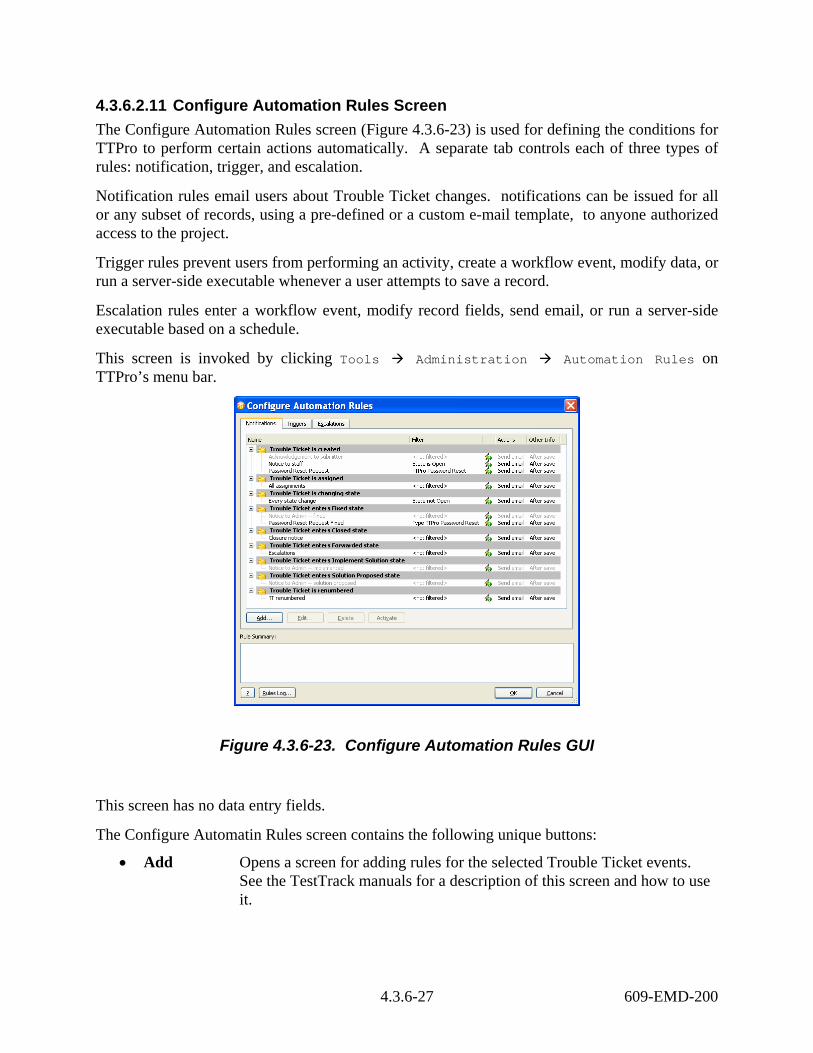
4.3.6.2.11 Configure Automation Rules Screen The Configure Automation Rules screen (Figure 4.3.6-23) is used for defining the conditions for TTPro to perform certain actions automatically. A separate tab controls each of three types of rules: notification, trigger, and escalation.
Notification rules email users about Trouble Ticket changes. notifications can be issued for all or any subset of records, using a pre-defined or a custom e-mail template, to anyone authorized access to the project.
Trigger rules prevent users from performing an activity, create a workflow event, modify data, or run a server-side executable whenever a user attempts to save a record.
Escalation rules enter a workflow event, modify record fields, send email, or run a server-side executable based on a schedule.
This screen is invoked by clicking Tools Administration Automation Rules on TTPro’s menu bar.
Figure 4.3.6-23. Configure Automation Rules GUI
This screen has no data entry fields.
The Configure Automatin Rules screen contains the following unique buttons:
• Add Opens a screen for adding rules for the selected Trouble Ticket events. See the TestTrack manuals for a description of this screen and how to use it.
4.3.6-27 609-EMD-200

• Add Default (Triggers tab only) Opens a screen for adding rules to perform actions on records that are not acted on by other triggers. See the TestTrack manuals for a description of this screen and how to use it.
• Edit… Opens a screen for adding rules for the selected Trouble Ticket events. See the TestTrack manuals for a description of this screen and how to use it.
• Delete Removes the selected rule • Activate Enables the selected rule • Rules Log… Exports the log for the selected rule to a text file for analysis or for use
with other tools
4.3.6.2.10 User Options screen The User Options screen (Figure 4.3.6-24) lets users specify personal preferences about how TTPro behaves. These cover displays, notifications, a personal dictionary, spell checking, and a few, other, more general features. This screen is invoked by clicking Tools User Options on TTPro’s menu bar.
Figure 4.3.6-24. Configure User Options GUI
Most panes on the screen present a series of radio buttons or check boxes. The Dictionary pane, though, provides a dialog for specifying the main dictionary to be used when spell checking and for adding custom words to the dictionary.
See the TestTrack manuals for more details about using this screen.
4.3.6-28 609-EMD-200

4.3.6.2.12 License Server Admin Utility The License Server Admin Utility screen (Figure 4.3.6-25) is the gateway to the collection of screens for managing TTPro license server operations. The GUI can be started only from the command line on the TTPro server machine, and access is generally limited to central TTPro system administrators.
Start the utility by typing: <TTPro-root>/splicsvr/bin & .
Figure 4.3.6-25. License Server Admin Utility GUI
This screen has no data entry fields.
The License Server Admin Utility screen contains the following unique buttons:
• Licenses Opens a screen for adding, editing, and deleting TTPro licenses, as well as for associating users with single-user, “named” licenses when applicable. From this screen, administrators can navigate to the Floating Licenses Used screen to view who is currently using TTPro floating licenses network-wide.
• Global Users Opens a screen for adding, editing, and deleting user profiles. See Section 4.3.6.2.13, Global Users Screen, below.
• Server Log Opens a screen for viewing, filtering, deleting and exporting license server log entries.
• Server Options Opens a screen for configuring log, license server, server database, LDAP, and password options. Password options cover requirements, restrictions and history.
See the Seapine License Server Admin Utility Guide, Version 3.1, for a thorough description of the screens mentioned above.
4.3.6.2.13 Global Users Screen The Global Users screen (Figure 4.3.6-26) lets TTPro administrators manage the user profiles of individuals who need to access to more than one TTPro project on the network. Double-clicking on any row in the list opens an Edit User screen containing the profile for the selected user. (See
4.3.6-29 609-EMD-200

Section 4.3.6.2.8) This screen is invoked by clicking on the Global Users button on the License Server Admin Utility GUI. (See Section 4.3.6.2.11)
Figure 4.3.6-26. Global Users GUI
This screen has no data entry fields.
The Global Users screen contains the following buttons:
• View Opens a screen for reading a user’s record in the license server database • Add Opens a screen for adding a new global user to the license server database. • Edit Opens a screen for changing a user’s record in the license server database • Delete Removes the selected user from the license server database • Undelete Opens a screen for restoring a previously deleted user’s profile
See the Seapine License Server Admin Guide, Version 2008, for a thorough description of the screens mentioned above.
4.3.6.2.14 TestTrack Pro Web Client’s Trouble Ticket Screen TestTrack Pro has a Web client that has all the features of the Windows client, including submission, querying, and modification of Trouble Tickets via an Internet Explorer 6.0 or higher, Netscape 7.0 or higher, or Firefox 2.0 or higher Web browsers. To reach the Web client, start the browser and enter the appropriate secure URL and port number. For example: https://<host>.gsfc.nasa.gov:<port_number>. The TTPro login window is then displayed as shown in Figure 4.3.6-27.
4.3.6-30 609-EMD-200

Figure 4.3.6-27. Web Login Window
The Project Selection window is used to choose which TTPro project .
Upon username and password verification, the TestTrack Project Selection window appears (Figure 4.3.6-28). Use this screen to specify which project to log in to. The Project picklist displays only the projects to which the user has access. If the picklist is empty or indicates that projects are loading, click Refresh after a few moments to retrieve a new list.
4.3.6-31 609-EMD-200

Figure 4.3.6-28. Project Selection Window
Table 4.3.6-16 provides a description of the TestTrack Project Selection window’s fields.
Table 4.3.6-16. TestTrack Project Selection Field Descriptions Field Name Data Type Size Entry Description
Project Selection * Required Name of the project to logon to Start at Selection * Required Name of list page to display initially
*Note: The size of a field with a "selection" data type can vary and the size is automatically adjusted to the size of the item selected from the selection list.
The TestTrack Project Selection screen has the following buttons:
• Refresh Retrieves the latest list of available TestTrack projects the user is authorized to access
• Login Logs the user into the selected project • Cancel Cancels the login request.
Upon successful login, the Trouble Tickets List page is displayed as shown in Figure 4.3.6-29. As with the Windows client, the Trouble Tickets list page identifies all Trouble Tickets returned by the filter the user selects. Rather than a menu bar, however, the web page has tabs and a series
4.3.6-32 609-EMD-200

of action links on the left side of the page to help users navigate and perform actions. To access a Trouble Ticket, users must select (click on) one or more Trouble Tickets, then click the View, Edit, or Delete buttons. A Logout button closes the user’s connection to the database properly and frees the user’s license.
Figure 4.3.6-29. Work with Trouble Tickets Web Page
4.3.6.3 Required Operating Environment The TestTrack server runs on a Linux-based machine; Linux-, Windows-, and Web-based clients are available. Appropriate information on operating environments, tunable parameters, environment variables, and a list of vendor documentation can be found in the EMD Release Notes document 914-TDA-400. To find the documentation for TestTrack Pro, refer to the Release Notes posted on the EMD Baseline Information System web page at your local site. The Release Notes document as well as the vendor manuals were distributed to ECS sites with TTPro.
4.3.6.3.1 Interfaces and Data Types TTPro’s Trouble Tickets are escalated into NCRs. Table 4.3.6-17 identifies this interface.
4.3.6-33 609-EMD-200

Table 4.3.6-17. External Interface Protocols Interface (facility) Type of Primary
Interface Protocols Type of Backup
Interface Protocols Comments
tt2ncr SOAP Manual Escalation of Trouble Tickets to the EDF
tt_licenseUsage SOAP Manual Logging of the number of TestTrack floating licenses in use at, typically, 30 minute intervals
tt_resetpasswd SOAP Manual Automatic reset of a user’s password upon submission of special trouble ticket by a TTPro administrator
4.3.6.4 Databases TTPro uses a native database management system bundled with the product. A distinct Trouble Ticketing database, also known as a project, exists for each ECS site. The Trouble Ticketing databases are:
• ECHO_TTs
• LaRC_TTs
• LPDAAC_TTs
• NSIDC_TTs
• Riverdale_TTs
4.3.6.5 Special Constraints Note that while most TTPro screens are accessible to all operators, only TTPro administrators have permissions to modify user permissions, security groups, project workflow, dropdown lists, and system notifications. Privileges are set according to DAAC policy.
4.3.6.6 Outputs Client output from TestTrack Pro (other than that displayed on GUIs) consists primarily of reports in HTML format presented on demand via the operator’s browser of choice. These operator-configurable reports can be printed or saved to a file. See Section 4.3.6.8 for a description of the variety of reports available.
TTPro also issues prompts when operator input is required, and writes a variety of error and informational messages to project and license server logs (see Section 4.3.6.7). Using the Server Options screen of the TestTrack Server Admin Utility and the License Server Admin Utility, TTPro administrators can control the amount of logging performed.
4.3.6-34 609-EMD-200
Users may also export selected TTPro records in either XML or tab- or comma-delimited text format. This is done via GUIs accessible by clicking File Export XML File Export or File Export Text File Export on the Trouble Ticket List screen’s menu bar.
4.3.6.7 Event and Error Messages TestTrack Pro does not have an error message guide. Below, however, is a sampling of the information typically logged by TTPro. (See Tables 4.3.6-18 through 4.3.6-20.)
Table 4.3.6-18. TTPro Startup.log File Messages Example Thu 03 Jul 2008 12:55:47 PM EDT <Info> Web Session Timeout DbDir=/usr/ecs/OPS/COTS/ttpro2008/TTServDb/TTDbs/Operations_NCRs/ UserName=Abdul Khan
Table 4.3.6-19. TestTrack Server Admin Utility Log File Messages Example
7/3/2008 3:30:17 AM Error 0 The TestTrack Server was unable to establish a connection with License Server on initialization. 7/3/2008 1:11:17 PM Error 0 Error polling on socket from client at [152.61.42.223] POLLHUP - Hang up. <not logged in> 7/3/2008 1:38:11 PM Unusual Activity 0 Attempting to login as "nrp0209735" using the Web client from 127.0.0.1 failed due to an invalid username and/or password. nrp0209735
Table 4.3.6-20. License Server Admin Utility Log File Messages Examples 06/27/2008 06:35:22 AM Error 0 Socket error when reading request from [127.0.0.1]: -191554640 ; Unrecognized Buffer Format. Server Session Not Logged In 06/27/2008 08:23:26 AM Unusual Activity 0 A user's attempt to log into the database from [127.0.0.1] failed due to an invalid password. Blscott
4.3.6-35 609-EMD-200

4.3.6.8 Reports TTPro can produce detail, list, distribution, and trend reports. Table 4.3.6-21 describes a sample of each.
Table 4.3.6-21. Reports Report Type Report Description When and Why Used
Detail of Open Defects
A full report of every Trouble Ticket not in a Closed state, sorted by Trouble Ticket number (see Figure 4.3.6-25).
When and if someone wants a copy of all open Trouble Tickets.
Summary of Problems
A list of the Trouble Tickets found or modified during the week prior to the report, containing only key details and sorted by Trouble Ticket number (see Figure 4.3.6-26).
When and if someone wants a list of the Trouble Tickets opened or updated during the past week.
Team Assignment Report
A distribution report identifying the Trouble Tickets found or modified during the week prior to the report, containing only key details and sorted by Trouble Ticket number (see Figure 4.3.6-27).
When and if someone wants to know how evenly work is distributed among the staff.
Trend of Open Defects and Types
A trend report identifying the number of Trouble Tickets of each problem type in the Open state over time, grouped and ordered by month (see Figure 4.3.6-28).
When and if someone wants to review (or forecast) trends among the types of problems reported.
4.3.6.8.1 Sample Reports Figures 4.3.6-30 through 4.3.6-33 provide samples of the reports described in Table 4.3.6-21.
4.3.6-36 609-EMD-200
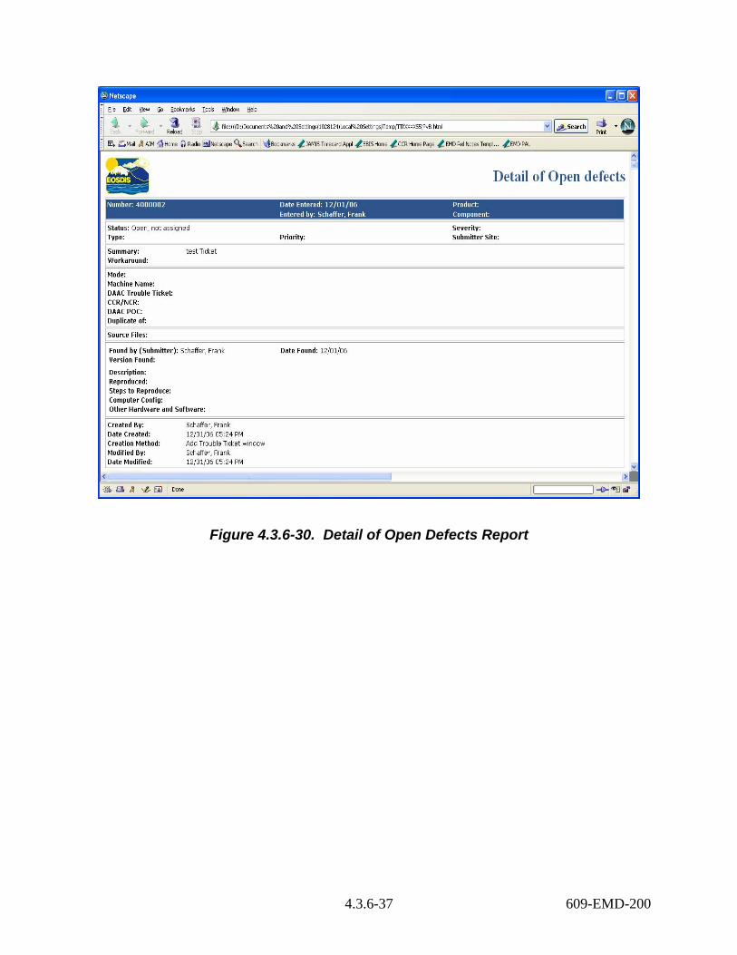
Figure 4.3.6-30. Detail of Open Defects Report
4.3.6-37 609-EMD-200

Figure 4.3.6-31. Summary of Problems found/modified Last Week Report
4.3.6-38 609-EMD-200

Figure 4.3.6-32. Number of Tickets by Submitter Report
4.3.6-39 609-EMD-200
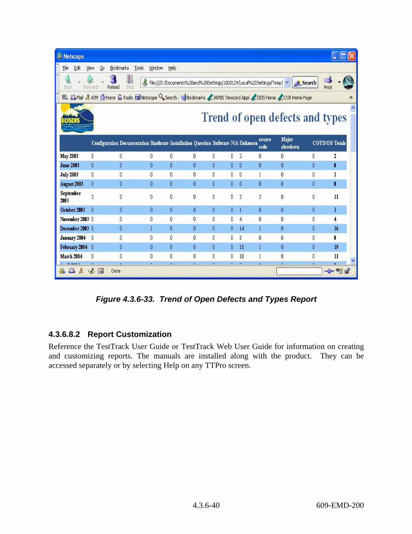
Figure 4.3.6-33. Trend of Open Defects and Types Report
4.3.6.8.2 Report Customization Reference the TestTrack User Guide or TestTrack Web User Guide for information on creating and customizing reports. The manuals are installed along with the product. They can be accessed separately or by selecting Help on any TTPro screen.
4.3.6-40 609-EMD-200