3g swap guideline
DESCRIPTION
3G Swap GuidelineTRANSCRIPT
Network Modernization and Swap Planning ProcessVersion 4.1
Page 2 of 47
document description
Title and version Network Modernization and Swap Planning Process for BSS and RANReferenceTarget Group Radio Network PlanningTechnology and SW release
2G, 2.5G, 3G
Related Service ItemsService Item numberAuthor Karri SunilaDate 23.2.2009Approver Ville Salomaa / Eric Kroon / Pekka Ranta
CHANGE RECORD
This section provides a history of changes made to this document
VERSION DATE EDITED BY SECTION/S COMMENTS
3.1 23.2.2009 Karri Sunila ALL NSN update4.0 27.6.2011 Lasse Vuokko ALL Combined 2G and 3G swap
planning documentation as one. General update.
4.1 24.10.2011 Lasse Vuokko 3.2, 3.4, 4.4, 5.1
Added Site configuration plan section. Minor other updates.
Copyright © Nokia Solutions and Networks. This material, including documentation and any related computer programs, is protected by copyright controlled by Nokia Solutions and Networks. All rights are reserved. Copying, including reproducing, storing, adapting or translating, any or all of this material requires the prior written consent of Nokia Solutions and Networks. This material also contains confidential information which may not be disclosed to others without the prior written consent of Nokia Solutions and Networks.

Page 3 of 47
Table of Contents
1. Scope..............................................................................................5
2. Introduction.....................................................................................5
3. Setup modernize project.................................................................63.1 Multivendor integration tests........................................................................................63.2 Site configuration plan..................................................................................................63.3 Swap strategy and roll-out plan....................................................................................73.4 Project acceptance KPIs and drive test methods.........................................................8
4. Setup methods and tools................................................................84.1 Area information...........................................................................................................84.2 Site visits – Technical Site Survey................................................................................94.3 Radio network parameter planning..............................................................................94.4 Create adjacency change procedure.........................................................................104.4.1 Adjacency creation tool..............................................................................................104.4.2 Define strategy for CI/LAC mapping during swap......................................................134.4.3 Data flow for creation of adjacencies.........................................................................134.4.4 Neighbour consistency check.....................................................................................134.4.5 Deletion of unused foreign objects.............................................................................144.5 Dataflow and schedule for swap................................................................................144.5.1 Data flow for creation of the network..........................................................................154.5.2 Consistency check of created WBTSs.......................................................................164.6 Deployment of the base station..................................................................................164.7 Other system updates................................................................................................16
5. Pre-modernize performance.........................................................165.1 Pre-swap network verification (drive test)..................................................................175.2 Pre-swap KPI collection.............................................................................................17
6. Prepare databuilds........................................................................186.1 Master plan.................................................................................................................186.2 Daily swap plan..........................................................................................................19
7. Prepare modernize BTS...............................................................197.1 Network creation........................................................................................................197.2 Consistency check.....................................................................................................207.3 Foreign BTS – other vendor cells...............................................................................207.4 Customer parameter translation.................................................................................207.5 Check parameter settings in OSS..............................................................................21
8. Integrate........................................................................................218.1 Radio network parameter implementation..................................................................218.2 Adjacency handling....................................................................................................22
Page 4 of 47
8.3 Adjacency handling methods.....................................................................................228.3.1 Method - Create double adjacency lists.....................................................................228.3.2 Method - Delete and create adjacencies directly.......................................................238.4 Adjacency update preparation procedure..................................................................248.4.1 Deletion of non-used adjacencies..............................................................................248.5 Swap site verification..................................................................................................25
9. Post Modernize.............................................................................259.1 Radio network performance monitoring during swap.................................................259.1.1 Recommended Reporting Suite reports.....................................................................259.1.2 Handover performance - Neighbour relations............................................................279.2 Post-swap network verification (drive test).................................................................27
10. BSS specific considerations for swap...........................................2710.1 Multilayer network......................................................................................................2710.2 Combined Handovers.................................................................................................2810.3 2G parameter cross-checks before swap...................................................................2910.4 Setup OSS performance monitoring..........................................................................3010.4.1 Standard 2G measurements......................................................................................3010.4.2 Other 2G measurements............................................................................................31
11. RAN specific considerations for swap...........................................31
12. Multivendor parameter and KPI/counter mapping........................3212.1 BSS KPI and parameter mapping references............................................................3312.2 RAN KPI and parameter mapping references............................................................3312.3 NSN default parameters.............................................................................................34
13. Reference material from past projects..........................................3413.1 BSS swap projects.....................................................................................................3413.2 RAN swap projects.....................................................................................................35
Appendices................................................................................................38Appendix A – Templates for Technical Site Survey Summary (TSSR) and site verification drive
test..............................................................................................................................38Appendix B – Example of a master plan for 2G and 3G..............................................................38Appendix C – Standard configurations for a 2G swap.................................................................41Appendix D – Antenna conversion...............................................................................................47
Page 5 of 47
1. ScopeThe scope of this document is to explain BSS or RAN swap procedure and preparation activities from the network planning point of view.
Swap (multi vendor swap or network modernization) is replacing old or other vendor network equipment with new equipment. Optimization which is often done after swapping the equipment is a different project and is not described in details in this document.
This document supports Flexi modernization cases and RG20/RU20 software level.
2. IntroductionThis document contains description of the network planning activities during the NSN BSS or RAN SWAP. This document is prepared based on the experiences derived from different SWAP projects in which NSN network is modernized or other vendor is replaced with NSN equipment. The network swap mainly consists of three main stages:
Pre-swap activities
During swap activities
Post-swap activities.
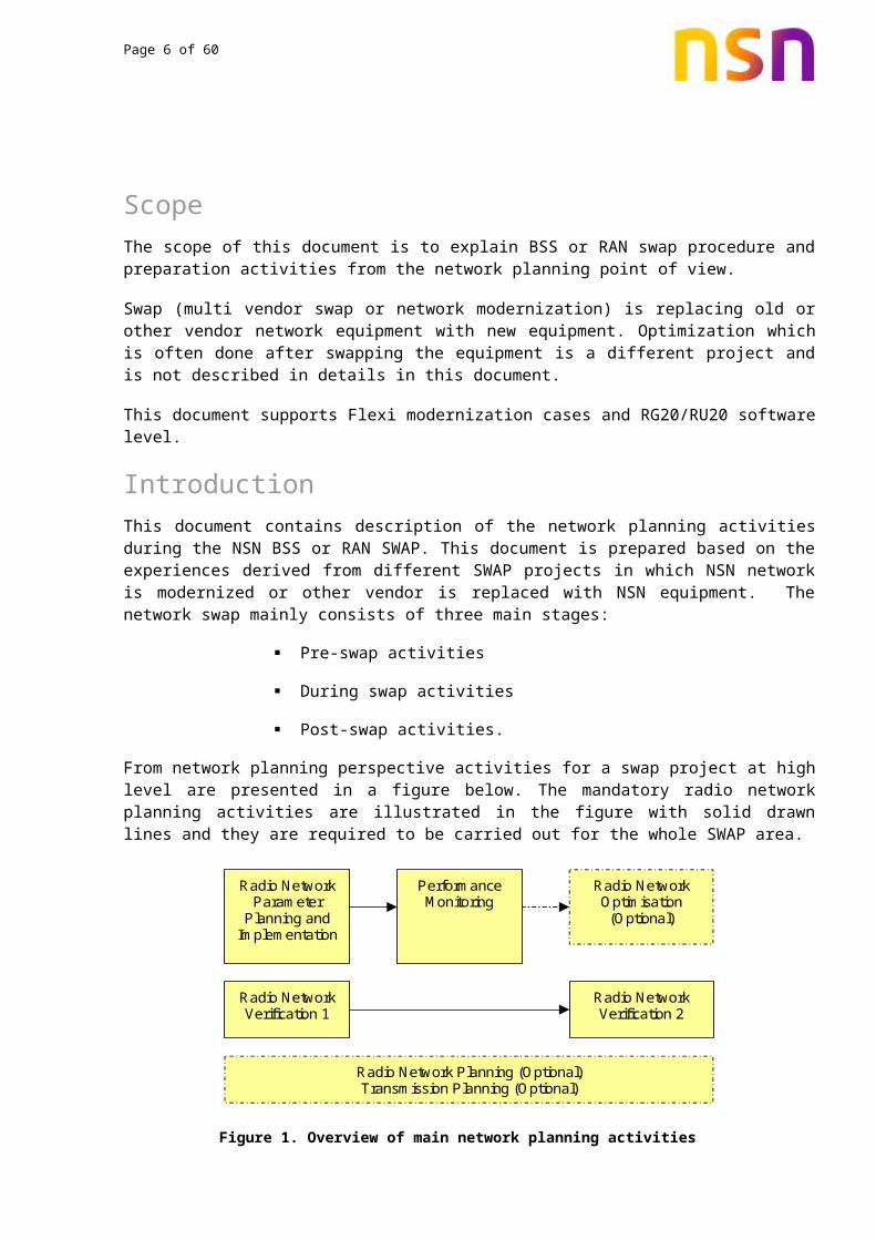
From network planning perspective activities for a swap project at high level are presented in a figure below. The mandatory radio network planning activities are illustrated in the figure with solid drawn lines and they are required to be carried out for the whole SWAP area.
Radio NetworkVerification 1
Radio NetworkOptimisation
(Optional)
Radio NetworkVerification 2
Radio NetworkParameter
Planning andImplementation
PerformanceMonitoring
Radio Network Planning (Optional)Transmission Planning (Optional)
Figure 1. Overview of main network planning activities
Flow diagram in Figure 2 illustrates the main steps within a swap project. Steps 1-3 consists of pre-swap preparations, steps 4-6 consists of swap execution and phase 7 consists of post-swap activities. Each of these main activities are considered in separate chapters in this document.
Page 6 of 47
Figure 2. Flow diagram of a swap or modernization project
3. Setup modernize projectThere are simultaneous tasks to be done before the actual swap. The following steps are required for preparations of the network swap / modernization.
3.1 Multivendor integration testsIn case of a vendor swap multivendor integration tests should be conducted in the customer’s network. The level of the tests should be decided based on the need for interoperability. If there is also a future need for interoperability in customer’s network then the target should be that all problems will get solved. On the other hand if there is only temporary need for interoperability then it might be enough to check if the functions such as handovers are working or not.
3.2 Site configuration planSite configuration plan defines mappings from existing site configuration to a new configuration including number of TRX and carriers, baseband capacity, transmission configuration, and planned features that affect site capacity.
Configuration mapping for TRX and carriers is usually one-to-one, unless capacity expansion is done together with the swap. Adding new TRX or carrier will impact RF or neighbor plan and this needs to be taken into account during the swap. If number of TRX or carriers is reduced, the cell capacity dimensioning should be verified based on earlier traffic to make sure there will be no RF blocking after the swap.
For 3G site baseband capacity need to be considered. A mapping from existing baseband capacity to required new capacity can be derived if enough information is available, otherwise the baseband requirements have to be determined based on dimensioning. The baseband capacity requirements depend on amount of traffic, number of HSPA users, number and type of HSDPA and HSUPA schedulers, and also on some network parameters such as initial and maximum bitrates, release timers, ...
Correspondingly in 2G use and allocation of SDCCH, GPRS/EDGE, AMR, and half rate need to be mapped from the existing setup to the new configuration.

Page 7 of 47
In vendor swap the requirements for site transmission may change. It need to be confirmed that the available transmission is sufficient for the new site, or if transmission need to be upgraded. Upgrades are likely to be required especially if site capacity is expanded during the swap.
If any changes are made to the RF chain of the site, the impact of the changes should be analyzed by link budget calculations to understand the impact to site coverage area. The coverage impacting changes include changes in cell powers (maximum power, BCCH power, CPICH power), use and type of combiners, cabling, antennas, receiver sensitivity, use of MHA, and use of RRH.
3.3 Swap strategy and roll-out planA roll-out plan defining what is swapped, when, and where need to be clearly defined before start of the project. Preferably the network elements should be swapped so that one continuous area is swapped at a time. This reduces potential problems due to inter-operability and also eases performance verification (OSS KPIs and drive tests). A roll-out plan could progress as in example in Figure 3. The roll-out plan can later be extended as a master plan which is followed throughout the project.
All the actions causing breaks to service should be scheduled for non-busy time of the day.
Figure 3, Example of a roll-out plan
It should also be agreed if any other network modifications are allowed during the swap or if the network is frozen for the swap period. If other modifications are allowed it should be taken care of that how these modifications are included to the swap process in order to avoid data inconsistency.
If any KPI affecting network changes are made during the swap period that are not directly part of the swap, it should be agreed with the customer how potential impact to the swap acceptance KPIs is handled.
Week1
Week2
Day1
Week3
Day4Day5
Day3
Day2
Page 8 of 47
3.4 Project acceptance KPIs and drive test methodsBefore starting a swap project it has to be defined how the project acceptance should be done.
• Based on stats from the network (aggregations must be defined)• Based on drive tests
Pre-swap KPIs including network statistics and drive tests should be collected before any actions have been done. KPI mapping between vendors should be confirmed and agreed before the swap project.
In case of a vendor swap it is recommended to verify that the acceptance KPI formulas are as similar as possible and that the exact counter pegging within the KPI is similar. Other vendor counters may be triggering earlier or later than NSN counterpart, and be pegged to a different message or instance. Due to this some failure cases may be included in one KPI but not in the another KPI and cause a delta between the KPI value between two vendors.
Since counter triggering points between vendors can be different all KPIs will not be 100% comparable. This should be mentioned before the swap and when required, new KPI threshold should be defined based on available information.
Note that KPIs may also be RAN/BSS release specific. References to multivendor KPI mapping can be found from chapters 12 and 12.2.
If KPI criteria are not fulfilled, optimization must be done. How to perform optimization after swap should be defined with customer before the project.
It may not be suitable to have same acceptance KPIs for all areas. If customer is requesting a long list of KPIs to cover all functionalities of the network in detailed level it is recommended to define a smaller area which is measured more deeply and if the results are acceptable then other areas do not need to have all KPIs but only generic system performance KPIs. Drive tests should also be limited in order to reduce the expenses. Measurement routes and methods need to be defined for acceptance and additional drive tests will be performed only if there are problems with network performance.
Drive test setup need to be agreed before any testing is started. In this phase at least following should be defined
• Tests to be performed (voice calls, data calls, locked to 2G or 3G, dual mode)• Availability of test number and type of calls (MTC/MOC, mobile to mobile or PLMN)• Required number and length of the calls• Data testing (only downlink or also uplink, FTP file size)• Use of scanner

Page 9 of 47
4. Setup methods and tools4.1 Area informationThe purpose is to get familiar with the swap area. Inputs required from customer regarding the demographic distribution of the areas like commercial area, residential area, industrial areas, and main business centers.
4.2 Site visits – Technical Site SurveyTechnical site survey (TSS) needs to be done for each of the site to be swapped. The purpose of the TSS is to do a site audit and verify the information provided by the customer and to verify that the new equipment could be installed. This task will be performed by Network Implementation. The following site information is checked and recorded during TSS:
Location (site co-ordinates)
Azimuth
Antenna tilt (Mechanical/Electrical)
Antenna type
Number of antennas
Height of the antennas
Site type (green field, rooftop, etc.)
Feeder type and length.
Combiners (By-pass, RTC, Wide Band Combiners 2:1, bias-T, …)
MHA configuration, if used
Availability of installation space
Power supply and battery backup
Physical access to the site
Site alert systems
Changes can be done if required. An example instructions for TSS for a GSM swap are described in Appendix A.
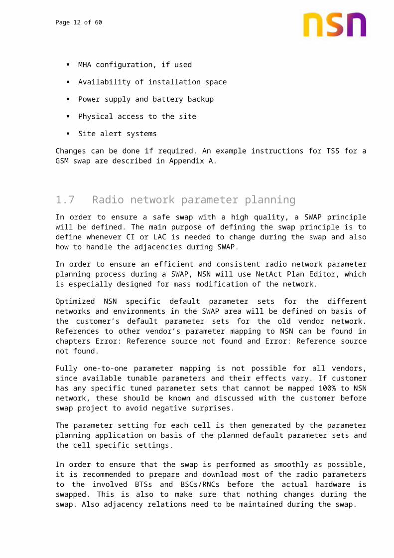
4.3 Radio network parameter planningIn order to ensure a safe swap with a high quality, a SWAP principle will be defined. The main purpose of defining the swap principle is to define whenever CI or LAC is needed to change during the swap and also how to handle the adjacencies during SWAP.

Page 10 of 47
In order to ensure an efficient and consistent radio network parameter planning process during a SWAP, NSN will use NetAct Plan Editor, which is especially designed for mass modification of the network.
Optimized NSN specific default parameter sets for the different networks and environments in the SWAP area will be defined on basis of the customer’s default parameter sets for the old vendor network. References to other vendor’s parameter mapping to NSN can be found in chapters Error: Reference source not found and Error: Reference source not found.
Fully one-to-one parameter mapping is not possible for all vendors, since available tunable parameters and their effects vary. If customer has any specific tuned parameter sets that cannot be mapped 100% to NSN network, these should be known and discussed with the customer before swap project to avoid negative surprises.
The parameter setting for each cell is then generated by the parameter planning application on basis of the planned default parameter sets and the cell specific settings.
In order to ensure that the swap is performed as smoothly as possible, it is recommended to prepare and download most of the radio parameters to the involved BTSs and BSCs/RNCs before the actual hardware is swapped. This is also to make sure that nothing changes during the swap. Also adjacency relations need to be maintained during the swap.
4.4 Create adjacency change procedureAdjacency handling is one of the most critical tasks in a swap project. In order to be able to maintain the normal handover traffic and possibility between all cells during the swap an intelligent procedure for defining and updating adjacencies must be defined.
In case of a network modernization, all adjacencies can be copied as they are from the old site. A vendor swap instead may be complicated due to adjacency handling. Intra-system adjacencies need to be updated always when a neighbouring site has been swapped. Also inter-system (2G->3G and 3G->2G) adjacencies need to be updated both ways to the newly swapped cells. Most efficient way to do this is to prepare a specific macro or script (Adjacency creation tool, see 4.4.1) which can retrieve all neighbour relations for requested cell and also create input files with updated adjacency definitions for all the needed OSSs. If it is not possible to use vendor specific input files then Excel can be used and adjacencies are created manually.
Some vendors allow more neighbours to be defined than NSN. In such case, use OSS HO statistics to choose the most important neighbours and make sure that those are implemented to the new NSN cells. Some post-swap optimisation for the neighbours may also be needed.
Strategy how adjacencies are handled during the swap and adjacency handling responsibilities need to be agreed.
4.4.1 Adjacency creation toolAdjacency handling can be done manually or automatically during a swap.
Manual adjacency handling is very resource demanding and the possibility of mistakes is high. Automatically adjacency handling by using a tool is the less resource demanding and the

Page 11 of 47
possibility of making a mistake is very low, if the tool is configured properly and the input is correct. Pay close attention to one-way neighbours if any defined.
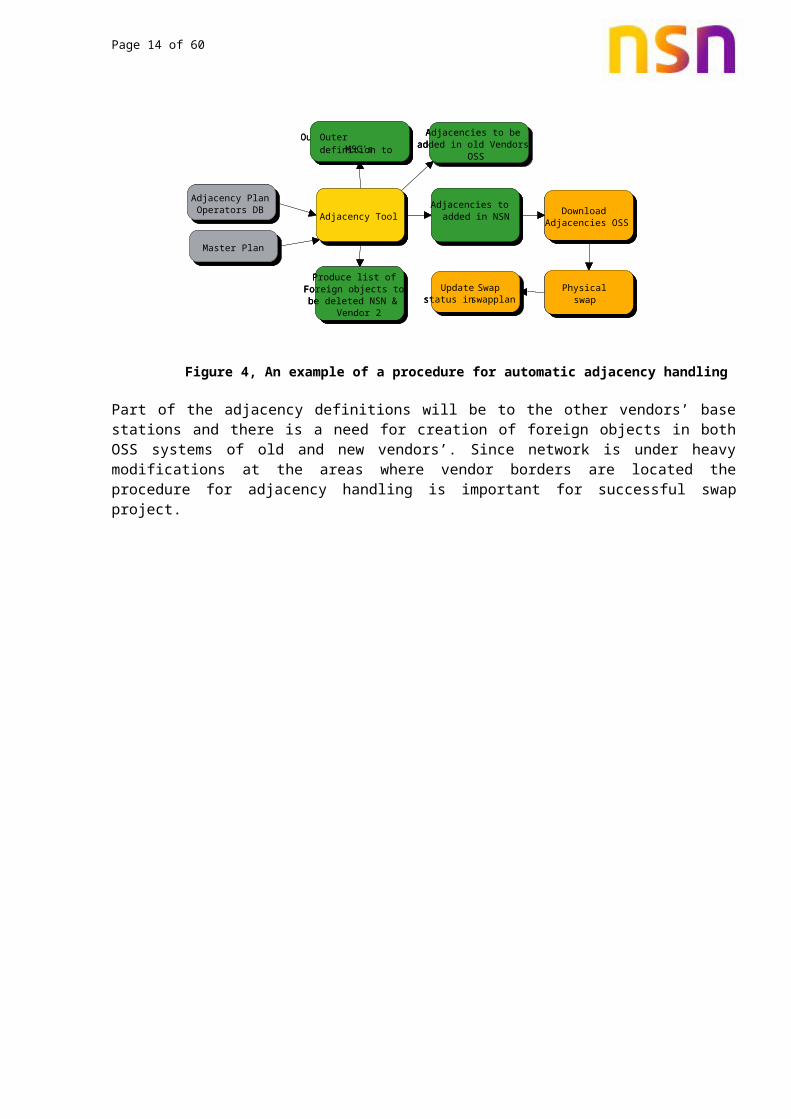
An example of a procedure for automatically adjacency handling is shown in Figure 4 and Figure5.
Figure 4, An example of a procedure for automatic adjacency handling
Part of the adjacency definitions will be to the other vendors’ base stations and there is a need for creation of foreign objects in both OSS systems of old and new vendors’. Since network is under heavy modifications at the areas where vendor borders are located the procedure for adjacency handling is important for successful swap project.
Adjacency PlanOperators DB
MasterPlan
Adjacency ToolAdjacencies to added in NSN Download
Adjacencies OSS
Physical SWAP
Update Swopstatus in swop plan
Produce list of Foreign objects to be deleted NSN &
Vendor 2
Adjacencies to be added in old Vendors
OSS
Outer definition to MSC's
Adjacency PlanOperators DB
MasterPlan
Adjacency ToolAdjacencies to added in NSN Download
Adjacencies OSS
Physical SWAP
Update Swopstatus in swop plan
Produce list of Foreign objects to be deleted NSN &
Vendor 2
Adjacencies to be added in old Vendors
OSS
Outer definition to MSC's
Adjacency PlanOperators DB
Master Plan
Adjacency ToolAdjacencies to added in NSN Download
Adjacencies OSS
Physical swap
Update Swapstatus in swap plan
Produce list of Foreign objects to be deleted NSN &
Vendor 2
Adjacencies to be added in old Vendors
OSS
Outer definition to MSC's
Page 12 of 47
Figure 5, Illustration of the use of foreign cells during the swap
Adjacency creation tool should be able to do the following tasks:
• Import existing pre-swap adjacency definitions for cell to be swapped including also incoming adjacencies
• Create updated adjacency definitions according to changes that are made for swapped cells ie. updated BSC/RNC, carrier, LAC…
• Create import files with updated adjacencies for all the vendors that are involved
Sometimes it is not possible to create these updated import files directly for other vendors’ OSSs. In that case the format of the adjacency files should be agreed to ease the processing of the adjacencies.
A1
C1
B2F_A1
F_C1
F_B2
F_B2
NSN AreaOld Vendor Area
A2
C1
B2
F_C1
F_B2
NSN Area
Old Vendor AreaF_C1
F_A2
A2
C2
B2
NSN Area
A1 is swapped to A2
C1 is swapped to C2
A1
C1
B2F_A1
F_C1
F_B2
F_B2
NSN AreaOld Vendor Area
A2
C1
B2
F_C1
F_B2
NSN Area
Old Vendor AreaF_C1
F_A2
A2
C2
B2
NSN Area
A1 is swapped to A2
C1 is swapped to C2
A1
C1
B2F_A1
F_C1
F_B2
F_B2
NSN AreaOld Vendor Area
A2
C1
B2
F_C1
F_B2
NSN Area
Old Vendor AreaF_C1
F_A2
A2
C2
B2
NSN Area
A1 is swapped to A2
C1 is swapped to C2
A1
C1
B2F_A1
F_C1
F_B2
F_B2
NSN AreaOld Vendor Area
A2
C1
B2
F_C1
F_B2
NSN Area
Old Vendor AreaF_C1
F_A2
A2
C2
B2
NSN Area
A1 is swapped to A2
C1 is swapped to C2
Page 13 of 47
4.4.2 Define strategy for CI/LAC mapping during swap
In order to select the most suitable strategy for handling of CI/LAC during the swap, following methods are evaluated:
• New CI, same LAC• Same CI, new LAC• Same CI, same LAC• New CI, new LAC
In the case of same CI and new LAC, the geographical LAC area can remain the same and only the numerical value changes. Often this is the easiest solution for swap, some other advantages of this are
Easy planning with one LAC mapping rule All ‘new’ cells can be defined in both BSC/RNC and MSC before the actual swap All new adjacencies can be defined before the actual swap if neighbour list length allows Easy fallback possible in case of any problems
In every case where changes are made it should be taken care of that RAC, URA and SAC values are also updated accordingly as needed. Easy fallback possibility in case the new NSN BTS does not function properly should be ensured.
4.4.3 Data flow for creation of adjacencies
Based on the roll-out plan from regions intra- and inter-system adjacency (Neighbouring Cells) data will be given to Implementation (OSS) in vendor specific input files. The data can be downloaded to the network from OSS before physical swap if double adjacencies are used. If all swapped adjacencies are to be deleted and recreated during the swap then adjacencies cannot be uploaded to the network beforehand but in any case they need to be delivered to Implementation (OSS) prior to the actual swap for verifications.
Following neighbour updates are required:
Update NSN intra-system neighbours to include swapped site as internal site, not external
Update other vendors intra-system neighbours to include the swapped site as external site, not internal
Add all inter-system neighbours to the new site as they were in the old site Update incoming inter-system neighbours to point correctly to the new site
One day before the actual swap all old adjacencies related to swapped cells should be queried from the OSSs. The order of the BTS swaps has to be known and for each individual swap there should be separate plans for deleting old adjacencies and creating new updated adjacencies. This task should be done with scripts (Adjacency creation tool, see section 4.4.1) that are able to read the adjacency data, prepare the modifications as specified and create input files for all systems that are involved.
Page 14 of 47
4.4.4 Neighbour consistency check A log file taken during updating of adjacent cell data should be provided to planning for checking of errors. The OSS dump should be provided also after the successful physical swap for further consistency check and creation of new neighbours.
4.4.5 Deletion of unused foreign objects
After a successful physical swap a list of foreign objects will be provided from Network Planning to Implementation. The foreign objects that are swapped should be deleted from the network, and it should be confirmed that no adjacencies anymore point to those foreign objects. If any such adjacencies remain, they should be corrected to point to the new site.
4.5 Dataflow and schedule for swapTo allow an easy implementation of all network elements a good interface between the Radio Network Planning group (responsible for the parameter definition), the Network Operations group (responsible for the implementation of the parameters in the network) and the Roll Out Services groups (responsible for installation etc. of equipment on site) needs to be established.
Figure 6, Timeline for network creation
In principle the dataflow between the groups can be simplified as the following illustration shows:
-1 Week
-2 Weeks
Time
Start of the physical swapPost-swap actions
Database provided to implementation Creation of the Network in
RNCs/BSCs
Dump from OSS downloaded and database transferred to NWP Plan Edit
Database provided to implementation

Page 15 of 47
List of sites to be swapped
OMC export of the old network
WBTS distribution in NSN RNCs
Prepare database for NetAct
import
Import data to NetAct
NSN database
(Plan Editor)
NetAct database
Consistency check for
data
Consistency check
Export processed
data
List of NSN cells to be
added in other vendor’s OSS
Daily swap plan
Adjacency handling tool
Other vendor’s database
Input files with new
neighbours for all OSSs
Actual swap including
adjacency modifications
OMC logfiles for troubleshooting
List of foreign cells that can
be deleted from NSN OSS
Imprt foreign cells to other vendor’s
OSS
Update swap plan
Verification of swapped site
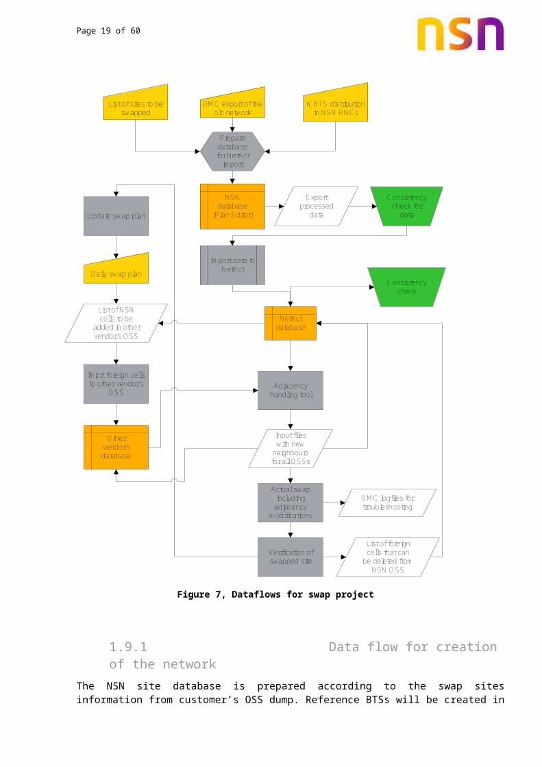
Figure 7, Dataflows for swap project
4.5.1 Data flow for creation of the network
The NSN site database is prepared according to the swap sites information from customer’s OSS dump. Reference BTSs will be created in the RNCs/BSCs with recommended set of BTS parameters from planning, prior to creation of actual BTSs. The swap BTSs will be created in the

Page 16 of 47
NSN network by a macro or by using Plan Editor as per the information provided by Planning with reference to the default reference BTSs.
• The Element IDs will be decided for implementation• OSS upload to be done after creation of all BTSs in the RNCs/BSCs
Time Frame: It is recommended that all network elements be created in the OSS at least 2 weeks before the physical swap
4.5.2 Consistency check of created WBTSs
After the upload of network data, Implementation (OSS) should provide network dump to planning for consistency check of the created BTSs, excluding adjacency plan as it will be implemented later.
Time Frame: It is recommended to provide OSS dump to Network Planning at least one week before of physical swap.
4.6 Deployment of the base stationActual deployment of the new base station is done following the standard procedures of the customer. Site documentation, hardware tests and measurements are performed as required.
4.7 Other system updatesThere might be other external systems that are using cell parameter info and needs to be updated during the swap. Customer is responsible for these updates but it is good to include all needed actions to swap plan. Here are few examples of other external systems that would require actions during the swap:
• Home Zone Billing –functionality• Area based KPI systems• Customer complaint / Error reporting systems• Business intelligence systems
Updates are performed based on the information of actual swap times in master plan for swap (see 6.1).
5. Pre-modernize performanceBefore any swap actions are carried out, the previous performance of the network need to be recorded. This performance level will give a reference point for post-swap performance.

Page 17 of 47
5.1 Pre-swap network verification (drive test)Prior to the SWAP, a network verification drive test will be carried out to evaluate the quality of the existing radio network. The drive test is intended to serve as reference for verification of the performance of the radio network after the SWAP has been completed.
A test route, covering all relevant BTS's in the SWAP area and its border areas, is agreed between the customer and NSN. In the drive test NSN will be following the roads defined in the drive test cluster definition by the customer.
After the pre-swap drive verify that the drive test data has good quality and enough data samples (e.g. number of calls, handovers, data throughput about what is expected, no failures due to test system...) and that all agreed test have been completed. A good pre-swap drive test is crucial for reference purposes since it cannot be repeated after the network swap has started.
5.2 Pre-swap KPI collectionAgree with customer which KPIs should be followed and monitored. Especially when a multivendor SWAP is done a proper KPI matching should be found prior to the project start. References to multivendor KPI mapping can be found from chapters 12 and 12.2.
Following KPIs are useful to follow before and after the swap. These could be found from RAN/BSS reporting suite system program report:
For 2G:
• TCH availability ratio• SDCCH performance• Voice call performance• Handover performance• (E)GPRS setup performance• (E)GPRS data volume and throughput• UL/DL RxQuality
For 3G:
• Cell Availability• RRC Performance• RAB AMR Performance• RAB UDI Performance • RAB PS Performance• Packet Call Performance• SHO Performance• HSDPA Performance• HSDPA Data Volume• HSDPA Serving Cell Change• HSUPA Performance• HSUPA Serving Cell Change
Make sure to collect enough KPI history data from the swap area. Collect also BTS and cell level data to see if certain cell was performing poorly already before the swap.

Page 18 of 47
After swap it is important to check that traffic has not reduced and performance has not degraded. It needs to be highlighted that comparing the results between different vendor’s statistics is difficult due to differences in the way the counters are pegged. The pre- and post-swap results could presented at cluster and cell level. Traffic related KPIs could be:
For 2G:
• SDCCH seizure attempts• TCH requests for a new call• UL/DL TBF allocations• Call time (voice)• (E)GPRS data volume• Total number of voice drops
For 3G:
• RRC Attempts• RRC Non Reg Attempts• RAB RT attempts• Call time (voice)• RAB NRT attempts• HSDPA selections• HSDPA data volume• HSUPA selections• Total number of voice drops
Results are compared against pre-swap results with proper mapping as in pre-swap evaluation.
6. Prepare databuildsAn approved method for BTS naming and sector number versus direction should be defined ahead of the project. Allocation of IDs and names such as SITE, BTS, CELL, TRX, LAPD, and BCF IDs and names should follow a predefined system. Depending on system, not all of the above mentioned IDs are required. Being able to build a good overview of the network by element IDs and name definitions will also ease the operation of the network.
Usually same naming and ID allocation method that the customer has used before can be used. If changes are made, they should be clearly agreed with the customers to avoid misunderstandings.
6.1 Master planA master plan is used as the key reference for Network Planning in the swap. The master plan is created based on input from the operator. Information needed is site name, sector name, direction, system, and TRX configuration.
A very important aspect in a swap is to have a common master plan. The master plan can contain all BTS in the swap area (existing and new BTS during the swap) and the corresponding configurations (existing and extensions). The master plan can also be used as an input for the adjacency handling. The master plan can also contain the BTS specific RF parameters that need to be implemented.
Page 19 of 47
All the needed parameters for BTS commission should be contained in the master plan. A list of mandatory parameters can be collected from the document ‘Commissioning Flexi Multiradio BTS’ which is part of the document ‘Nokia Solutions and Networks WCDMA RAN, Rel. RU20, Operating Documentation’ for 3G or document ‘GSM/EDGE BSS, Rel. RG20(BSS), Operating Documentation’ for 2G. The documents can be downloaded from references 1 and 2. Simplified examples of master plan for 2G and 3G are presented in Appendix B.
The master plan can also provide information for Logistics, Roll-out plan, ET-plan (transmission plan) and for the Site creation process in Plan Editor (Access database).
It is recommended that not only sites that are on air at the moment of swap are included in to the master plan, but also new sites coming to air during the swap period can be included. New sites can be treated as sites to be swapped and the data preparation (cell parameters and adjacencies) of those sites can be done together with the data preparation for the sites to be swapped. This will reduce overlapping work and also ease change management during the swap.
6.2 Daily swap plan Based on the cluster information available the daily swap plan is prepared by Implementation. The daily swap plan should follow the roll-out plan. Regional project managers will provide this information to Network Planning and to the customer one week prior to the physical swap.
Required data builds can then be prepared for sites according to the plan and agreed adjacency change procedure.
7. Prepare modernize BTS7.1 Network creationBefore the swap can start the network needs to be created in the RNCs/BSCs. The Master plan is used as an input to generate the data needed for the creation of all network objects.
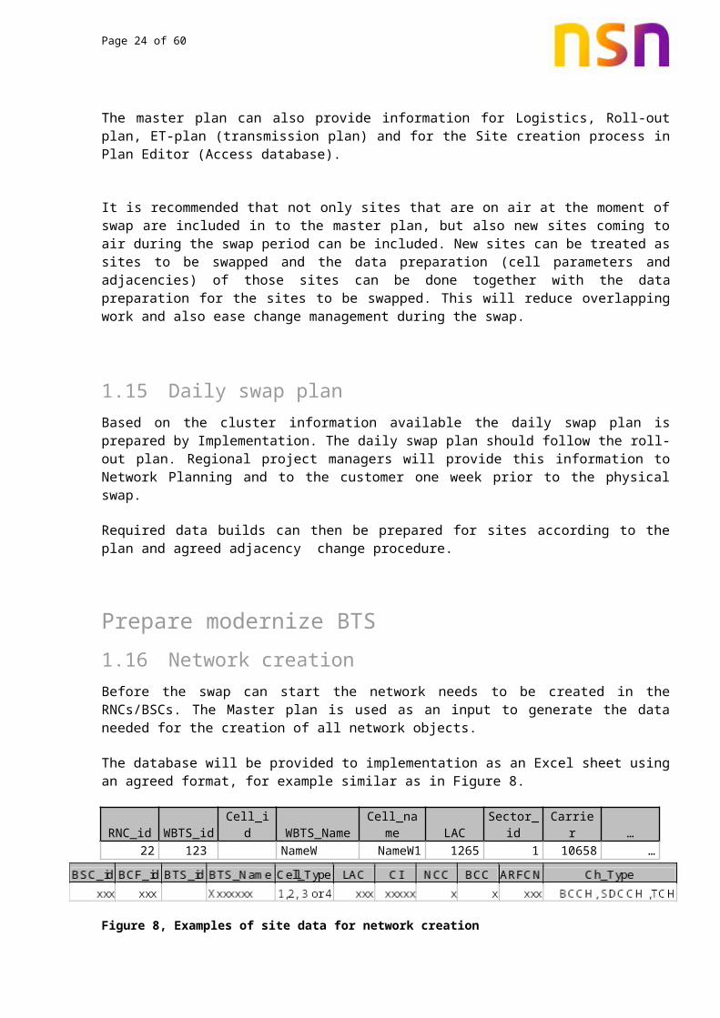
The database will be provided to implementation as an Excel sheet using an agreed format, for example similar as in Figure 8.
RNC_id WBTS_id Cell_id WBTS_Name Cell_name LAC Sector_id Carrier …22 123 NameW NameW1 1265 1 10658 …
Figure 8, Examples of site data for network creation
The cell creation will then start in the RNCs/BSCs. Creation will be done based on the data provided in the Excel sheet and according to the appropriate parameter templates depending on the cell type and mapping of the parameters (see 7.4). The actual site creation can be done with MML macros, after which BSC/RNC upload is done and rest of the parameters are implemented

Page 20 of 47
with PlanEditor. Alternatively the whole process can be done with Plan Editor and OSS CM tools.
This database should be provided at least 2 weeks prior to the first physical swap.
7.2 Consistency checkOnce the cells have been created in the RNCs/BSCs, a download of all the network elements from OSS will be done. This download will be integrated to the Master Plan using Plan Editor transfer facility and the data will then be checked and any inconsistency or missing information detected. Information about parameter assessment can be found from reference 3.
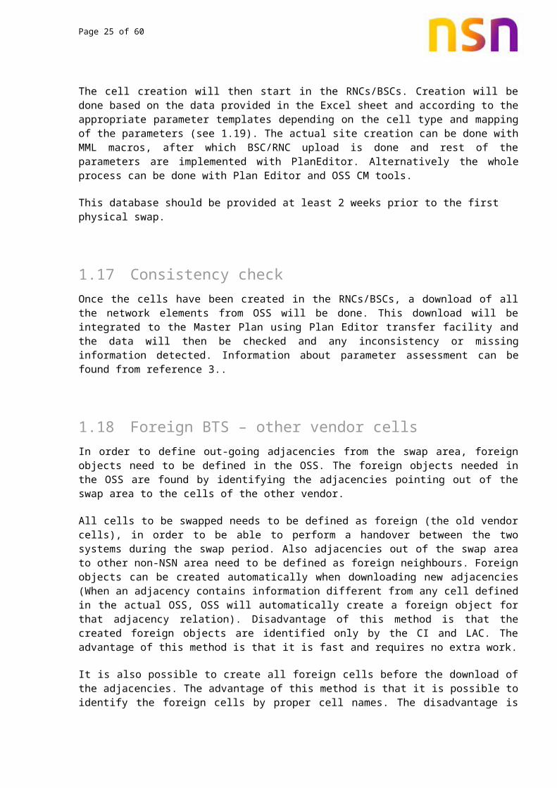
7.3 Foreign BTS – other vendor cellsIn order to define out-going adjacencies from the swap area, foreign objects need to be defined in the OSS. The foreign objects needed in the OSS are found by identifying the adjacencies pointing out of the swap area to the cells of the other vendor.
All cells to be swapped needs to be defined as foreign (the old vendor cells), in order to be able to perform a handover between the two systems during the swap period. Also adjacencies out of the swap area to other non-NSN area need to be defined as foreign neighbours. Foreign objects can be created automatically when downloading new adjacencies (When an adjacency contains information different from any cell defined in the actual OSS, OSS will automatically create a foreign object for that adjacency relation). Disadvantage of this method is that the created foreign objects are identified only by the CI and LAC. The advantage of this method is that it is fast and requires no extra work.
It is also possible to create all foreign cells before the download of the adjacencies. The advantage of this method is that it is possible to identify the foreign cells by proper cell names. The disadvantage is that the method requires more manual work to type in all the foreign objects unless scripts are used to do it.
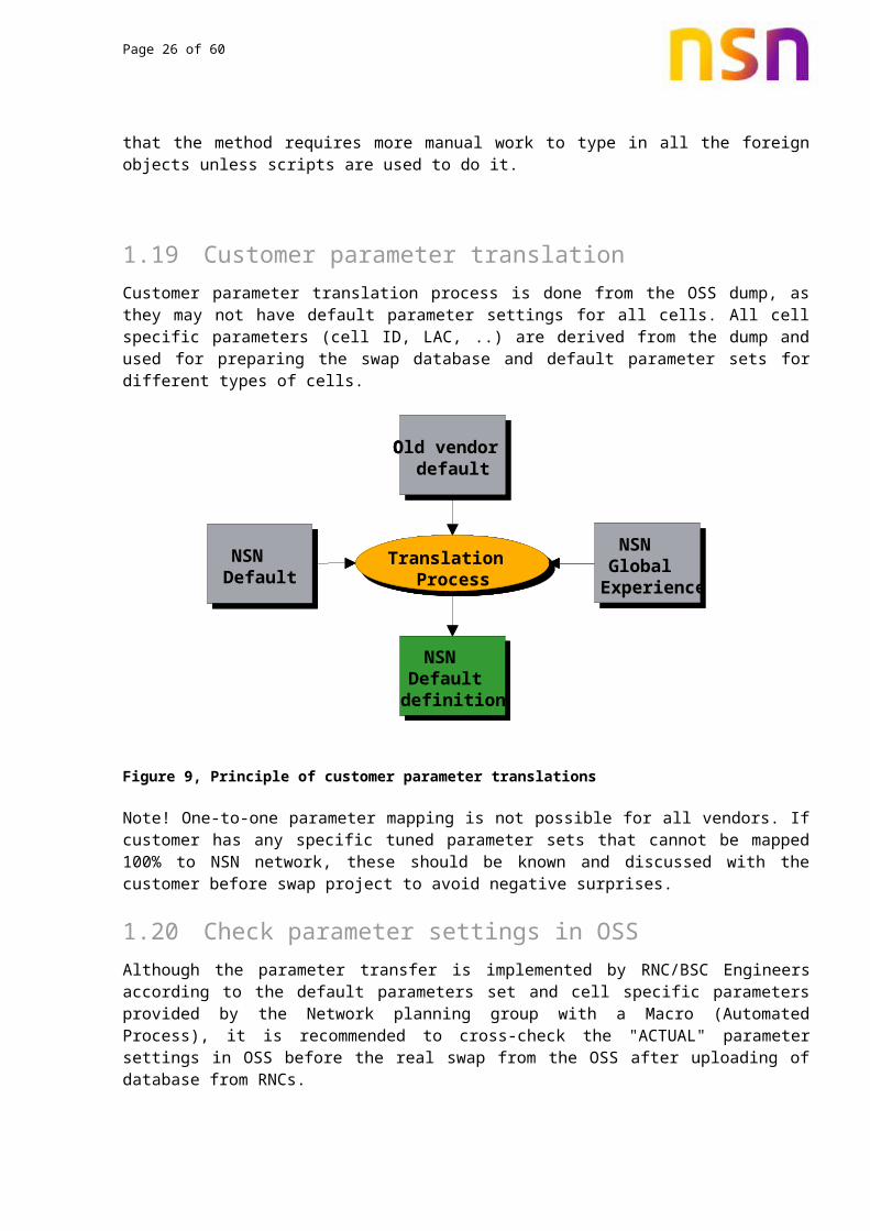
7.4 Customer parameter translation Customer parameter translation process is done from the OSS dump, as they may not have default parameter settings for all cells. All cell specific parameters (cell ID, LAC, ..) are derived from the dump and used for preparing the swap database and default parameter sets for different types of cells.
Page 21 of 47
Figure 9, Principle of customer parameter translations
Note! One-to-one parameter mapping is not possible for all vendors. If customer has any specific tuned parameter sets that cannot be mapped 100% to NSN network, these should be known and discussed with the customer before swap project to avoid negative surprises.
7.5 Check parameter settings in OSSAlthough the parameter transfer is implemented by RNC/BSC Engineers according to the default parameters set and cell specific parameters provided by the Network planning group with a Macro (Automated Process), it is recommended to cross-check the "ACTUAL" parameter settings in OSS before the real swap from the OSS after uploading of database from RNCs.
Based on the daily swap plan the right sites can be checked. In case of problems in the created parameters, corrections are needed and can be requested to Implementation before the physical swap.
8. Integrate8.1 Radio network parameter implementationThe radio network parameters will be implemented in the sites created in the RNCs/BSCs from
A macro application running from the RNC/BSC MML with reference to pre-defined reference BTSs. Once the sites are created, OSS upload will be done for updating OSS database. This OSS database will be used for Parameter Planning Application (Plan Editor) for further modifications to the BTSs and RNCs/BSCs via OSS.
The whole process can be done with OSS CM tools and Plan Editor. This is the recommended way and requires also less steps.
After the final parameters are planned with Plan Editor, the radio network parameters will be downloaded to the network via OSS. More about Plan Editor can be found from the reference 3.
NSN Default
NSN Global
Experience
Old vendor default
NSN Default definition
Translation Process
NSN Default
NSN Global
Experience
Old vendor default
NSN Default definition
Translation Process
NSN Default
NSN Global
Experience
Old vendor default
NSN Default definition
Translation Process

Page 22 of 47
8.2 Adjacency handlingAdjacency handling is one of the most critical tasks in a swap. In order to be able to maintain the normal handover traffic and possibility between all cells during a swap an intelligent procedure for defining adjacencies must be defined.
Input to the adjacency-handling tool is the adjacency plan and the master plan. The tool must produce an adjacency list for NSN and one for the old vendor. Adjacencies to NSN can be imported to OSS by using the "Planning File Transfer". Plan Editor is very suitable for generating this planning file. Since Plan Editor is based on an Access database, all tables needed to create the adjacencies can be imported to that database. Remember to update also inter-system adjacencies both ways.
Outer definitions for MSC are very important if the swap is spread over several MSCs. It is a MSC supplier related item, when outer definitions in MSCs need to be updated. More information about neighbour planning can be read from the references 5-7.
8.3 Adjacency handling methodsThere are two main methods for handling adjacencies during the swap: One is to create simultaneously adjacencies to/from old and new cells so that adjacencies do not need to be modified during the actual swap of a site. This method is not suitable for cases where adjacency lists are close to full because every adjacency should be doubled.
Second possibility is to modify adjacencies immediately before and after the actual swap in such a way that all old adjacencies are transferred to new cell as they were before swap. The requirement for this method is well functioning methods for adjacency imports, deletions and creations.
It is also possible to create common updated adjacency plan for all the cells that are to be swapped in near future like next night. The risk of this method is that if one of the swaps failures there is not easy way of doing rollback for the adjacencies of that site.
These two methods for adjacency handling are discussed deeper in following paragraphs.
8.3.1 Method - Create double adjacency lists
This method is suitable when the adjacency lists in the network are short and can be easily limited to 16 or under adjacencies per system.
During swap you have to create a double handover list. To make such a double entry the maximum allowed neighbours per BTS is 16 (since the maximum is 32). Since the swap is performed as a one to one swap, the neighbour relations will be doubled during the swap.
The new cells are assigned new LACs and CIs. The neighbours of the old vendor cells will be added to the neighbour list of new NSN cells. After the swap of the old vendor cell the neighbour relations should be deleted in old vendor RNCs but at the same time the new swapped cells

Page 23 of 47
should be added as a neighbour to its neighbouring cells. The principle of the neighbour relation swap is shown in figure below.
Since some cells have more than 16 adjacency relations, all adjacency relations cannot be implemented before the swap, but they will be added and deleted in small blocks. One block will contain the adjacency relations to be added or deleted for e.g. the next 2 days of the swap period. In Rural areas it is normally possible to add all adjacency relations before the swap (Adjacency swap period e.g. 5 days), but in urban areas the maximum of 32 measurement frequencies might be exceeded in some cells, especially in dual band or multi-layer areas. The adjacency relations to be added or deleted in the following swap period are handled by an adjacency tool developed by NSN especially for a swap project.
One solution of adjacency handling during swap is to collect HO stats before swap and take the 16 cells where most of handovers have been done and temporary delete the rest of the neighbours. This way the degradation of quality is been minimized. The deleted neighbours should then be recreated after the swap.
In case of a 2G swap, it should be noted that to be able to implement double adjacency relations in the systems (NSN and old vendor) before the swap, BSIC of the new cell must be changed. It is not possible to have 2 measurement frequencies with the same BSIC in the adjacency list. BSIC consist of NCC + BCC. There are two methods to change BSIC; either NCC or BCC. For example, NSN will change temporarily the NCC value and will fall back to the old once the swap is complete.
8.3.2 Method - Delete and create adjacencies directly
If adjacency lists are full or close to full this method should be used. Before each swap all related adjacencies are deleted and new adjacencies are created for the new NSN cell as they were for swapped old cell. The advantage of this method is that all the results are final and the risk of errors due to temporary solutions is avoided. This method is also more flexible for the adjacency changes because adjacency exports are performed close to actual swap. The disadvantages are that the downtimes of the sites might be a bit longer due to adjacency updates depending on the performance of the OSSs that are involved. This method also requires good scripts that will generate adjacency input files for all systems.
Old vendor CELL
Old vendor CELLOld vendor
CELL TO swap
NSN CELL New LAC & CI
Figure 10, Neighbor relation swap
Page 24 of 47
Create new WBTS
Block old WBTS
Delete old adjacencies
Create updated adjacencies
Activate new WBTS to live network
Verify that new WBTS is working
Delete old WBTS
Intra frequency Inter frequency Inter system Both directions!
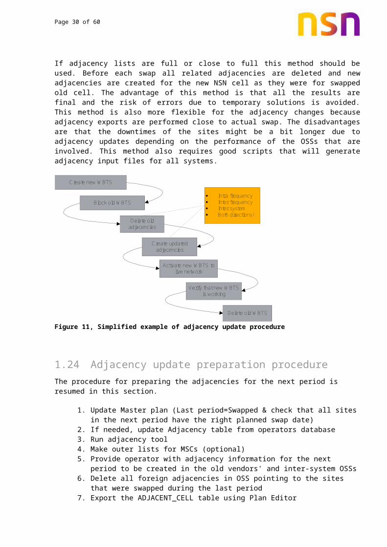
Figure 11, Simplified example of adjacency update procedure
8.4 Adjacency update preparation procedureThe procedure for preparing the adjacencies for the next period is resumed in this section.
1. Update Master plan (Last period=Swapped & check that all sites in the next period have the right planned swap date)
2. If needed, update Adjacency table from operators database3. Run adjacency tool4. Make outer lists for MSCs (optional)5. Provide operator with adjacency information for the next period to be created in the
old vendors' and inter-system OSSs6. Delete all foreign adjacencies in OSS pointing to the sites that were swapped during
the last period7. Export the ADJACENT_CELL table using Plan Editor8. Import adjacency file to OSS and Upload adjacencies to RNCs /BSCs
8.4.1 Deletion of non-used adjacencies
Non-used adjacencies to e.g. old cells that have been swapped, can be easily deleted, by deleting the corresponding foreign objects of the old cells. This will clean up the adjacency plan after the swap. This applies to the method where double adjacencies are used. In other methods there should not be adjacency leftovers.
Note! It is recommended to change the identification of the foreign cells after the swap (e.g. change CI/LAC or Cell name of swapped foreign object). This will make the network easier to operate from OSS.
Page 25 of 47
8.5 Swap site verificationImmediately after the physical swap of the site, drive test shall be performed. A quick drive test is done to verify the implementation of the correct RNP parameters. The drive test will ensure that handovers between the cells are working properly, sectors are not swapped, and that call set-up success rate and drop call rate meets the criteria agreed for the swap project. If any performance problems are found, troubleshooting for the particular cell or site will be performed using Reporting Suite Reports or other suitable tools.
All the swapped sites are individually checked for problems related to:
• CSSR• HO / SHO, preferably handovers to neighbouring foreign cells should be inluded• Coverage• Total cross feeders between the sectors• Partial cross feeders between the sectors
The data for each swap site is recorded as a log file as well as saved as required by customer. Any found problems are forwarded to the BTS group for rectification. After problem solving has been confirmed by the BTS engineer the cells/sites are verified again. See also cluster tuning WI, reference 8. Example of 2G drive test template is in Appendix A.
9. Post Modernize9.1 Radio network performance monitoring during swapThe purpose of this activity is to detect and correct any unintentional hardware or parameter deficiencies at the earliest possible time. In this way any temporary decrease in network quality is minimized.
It is recommended to keep problem record during swap. All the problems encountered will be written down and will be solved with customer as soon as possible.
However some performance degradation is expected at border of the swapped and old cells. This is due to multiple reasons such as:
Inter-vendor SHO/HO success rate can be lower than intra-vendor At swap border number of location are updates increase. In 2G this may cause SDCCH
blocking, as the cells are not dimensioned for LAC border. Using dynamic SDCCH allocation should minimize the impact
Continuous adjacency updates due to the swap activity
General information about network KPI analysis can be found from reference 9.
9.1.1 Recommended Reporting Suite reports
KPI statistics from the OSS are used during the swap for evaluation of the basic performance of each cell. Some selected KPI's and criteria are defined in order to detect any unexpected
Page 26 of 47
hardware problems or wrong parameter settings. KPI statistics can also be used to evaluate the general area performance during the swap. It is recommended to use Benchmarking KPI during the swap. Needs for KPI analysis / Drive test analysis are always contract and project specific.
Example of 2G KPIs are presented below. Official benchmarking KPI can be found from Jump portal, reference 10.
KPI Formula Threshold (%)
SDCCH access probability Csf_1 > 98,5
SDCCH real blocking Blck_5a < 1.0
TCH call blocking, before DR Blck_8i < 2.0
TCH drop call(dropped conversation) % Dcr_5a < 2.0
Total handover failure ratio Hfr_2a < 10,0
In case any of the KPI degradation, investigations should be started to see if the history of the cell performance was fine. In case performance degeneration is not caused by hardware or parameter problems, but by the network plan, the cell in question is transferred to post-swap optimization process.
During the swap close KPI monitoring is needed with daily or hourly statistics, depending on the schedule and agreement with the customer.
Immediately after swap following Reporting Suite reports should be checked for all new cells for any unexpected performance changes or degradation. The reports and details can be found from reference 11.
For 2G:
• RS_001: 2G System program• RS_ 063: parameter audit – to ensure that database is downloaded to the network
correctly• RS_153: handover adjacent cell stats – to check that Handovers are occurring to
the defined neighbors• RS_211/216/213: BTS/Cell doctor, in case of expected problems – Cell Specific• RS_206/209
For 3G:
• RSRAN000: System Program• RSRAN073: Service/Session Accessibility Analysis• RSRAN079: Service/Session Retainability Analysis• RSRAN028: Soft Handover Performance• RSRAN046: SHO Adjacencies • RSRAN045: ISHO Adjacencies• RSRAN092: HSPA Overview

Page 27 of 47
9.1.2 Handover performance - Neighbour relations
If any degradation is observed in handover performance (intra- of inter-system), following Reporting Suite reports will help to identify if there is a certain adjacencies causing the problem.
For 2G:
• RS_153: Adjacencies having high HO failure ratio• RS_154: HO attempt case distribution by cells
For 3G:
• RSRAN044: IFHO Adjacencies• RSRAN045: ISHO Adjacencies• RSRAN046: SHO Adjacencies
To improve HO performance of the cells first the neighbours should be reviewed for any neighbour parameter mismatches. The best way for finding missing neighbours is to analyze the drive test logs. If detected set reporting feature is enabled in 3G, missing neighbours can also be found from OSS statistics.
9.2 Post-swap network verification (drive test)A second Radio Network Verification will be carried out after the swap has been completed, i.e. at a time, when the network is operational.
Aim to carrying out the second set of drive tests under similar traffic conditions as before, route, weekday and time of the day for the tests should be similar to those of the first verification.
Measurements and KPI results for both of the drive tests will be compared and evaluated in details.
10. BSS specific considerations for swap10.1 Multilayer networkIf the network to be swapped is dual band, from the OSS dump the dual band strategy can be found or alternatively discussing with the customer. Based on the strategy the parameters can be modified.
In NSN dual band strategy, (traffic reason or Umbrella) HO feature is used to push the traffic between 900 & 1800 layers as well as between Macro and Micro cells. The feature with the recommended settings is discussed next.

Page 28 of 47
10.2 Combined Handovers
900 Layer / Macro
1800 Layer/ Micro
LEV, QUAL Umbrella HO & PBGT
PBGT, QUAL, LEV
FMMS FMT – Umbrella HO QUAL quality reason HO PBGT power budget HO LEV level HO
PBGT, QUAL, LEV
UPPER
LOWER
Figure 12 Principle of multilayer network and different handover between layers
The handover to the upper layer will be triggered by a standard Rx Level Ho (Either DL or UL). That means as soon as the level of the lower layer gets below the defined minimum (for e.g. -90 /-87 dBm) a handover to the upper layer will take place. In parallel a quality handover (due to bad quality or interference) to the upper layer will be possible as well.
Between the cells of the same layer a power budget, level or quality handover is possible.
Figure 13 Example of multilayer network parameterization
Multi-layer Handovers & Parameters

Page 29 of 47
03MAC1 03MAC2 AUCL = -47 dBm
FMT = 0
PMRG = 6 dB
LMRG = 3 dB
QMRG = 0 dB
PRI = 3
ACL = Not Used
DRT = -90 dBm
DL Lev = -90 UL Lev = -87
DL Qual = 4 UL Qual = 4
Loadthreshold = 70
DR method = 1
03MIC3
03MIC1
AUCL=-75dBm
FMT = 10
PMRG = 6 dB
LMRG = 3 dB
QMRG = 0 dB
PRI = 4
ACL = Lower
AUCL=-47dBm
FMT = 0
PMRG = 6 dB
LMRG = 3 dB
QMRG = 0 dB
PRI = 5
AUCL=-47dBm
FMT = 0
PMRG = 63 dB
LMRG = 3 dB
QMRG = 0 dB
PRI = 3
ACL = Upper
DRT =-90dBm DL Lev = -90 dBm UL Lev = -87 dBm
DL Qual = 4 UL Qual = 4
Loadthreshold = 70%
Figure 14 Example of multilayer network parameterization
10.3 2G parameter cross-checks before swapFollowing cross-checks are recommended before the actual swap to make sure correct planned parameters are implemented to the network.
Reporting Suite: Default parameter audit report (063) (all cells)
Cross-checks
- SDCCH configuration (some small and large configuration cells)
- The default SDCCH configurations
- CI/ BCC/NCC/LAC (check if new NCC/LAC is used)
- Number of TRX's & respective Frequencies
- HO definitions and settings:
- Outgoing relation on new cells
- Incinomg relations on new cells (same OSS)
- Incoming relations on new cells (from other OSS's : other vendor)
Inputs
- Daily Swap plan
Page 30 of 47
- Parameter Dump
- RS_211 Report (Reporting Suite)
Outputs
- NetAct Plan Editor export file incase of parameter modification
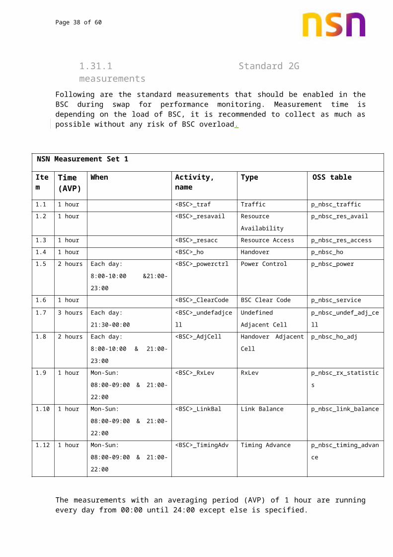
10.4 Setup OSS performance monitoringFor performance monitoring different measurements should be set-up in OSS in an optimized way such that OSS load remains under control. The standard measurements to be set-up in OSS are as follows.
10.4.1 Standard 2G measurementsFollowing are the standard measurements that should be enabled in the BSC during swap for performance monitoring. Measurement time is depending on the load of BSC, it is recommended to collect as much as possible without any risk of BSC overload.
NSN Measurement Set 1
Item Time (AVP)
When Activity, name Type OSS table
1.1 1 hour <BSC>_traf Traffic p_nbsc_traffic
1.2 1 hour <BSC>_resavail Resource Availability p_nbsc_res_avail
1.3 1 hour <BSC>_resacc Resource Access p_nbsc_res_access
1.4 1 hour <BSC>_ho Handover p_nbsc_ho
1.5 2 hours Each day:
8:00-10:00 &21:00-23:00
<BSC>_powerctrl Power Control p_nbsc_power
1.6 1 hour <BSC>_ClearCode BSC Clear Code p_nbsc_service
1.7 3 hours Each day:
21:30-00:00
<BSC>_undefadjcell Undefined Adjacent
Cell
p_nbsc_undef_adj_cell
1.8 2 hours Each day:
8:00-10:00 & 21:00-23:00
<BSC>_AdjCell Handover Adjacent Cell p_nbsc_ho_adj
1.9 1 hour Mon-Sun:
08:00-09:00 & 21:00-22:00
<BSC>_RxLev RxLev p_nbsc_rx_statistics
1.10 1 hour Mon-Sun:
08:00-09:00 & 21:00-22:00
<BSC>_LinkBal Link Balance p_nbsc_link_balance
1.12 1 hour Mon-Sun:
08:00-09:00 & 21:00-22:00
<BSC>_TimingAdv Timing Advance p_nbsc_timing_advance
The measurements with an averaging period (AVP) of 1 hour are running every day from 00:00 until 24:00 except else is specified.
Page 31 of 47
10.4.2 Other 2G measurementsSome other types of measurements are available. These will mainly be used for trouble shooting purposes and analysis of problems occurred during SWAP. They will be programmed by OSS on demand of the NSN optimization group in order to check the infected network elements. The number of extra measurements will be kept minimal: 20 measurements, in order not to overload the OSS.
Other raw measurements.
2.1
Name<BSC>_load
TypeLoad
OSS-tableP_nbsc_load
2.2 <BSC>_avail Availability P_nbsc_avail
2.3 <BSC>_OSI1 OSI level 1 P_nbsc_osi1
2.4 <BSC>_OSI2 OSI level 2 P_nbsc_osi2
2.5 <BSC>_OSI3 OSI level 3 P_nbsc_osi3
2.6 <BSC>_OSI4 OSI level 4 P_nbsc_osi4
2.7 <BSC>_cc BSC Clear Code Measurements P_nbsc_cc
2.8 <BSC>_ccpm BSC Clear Code Measurements PM P_nbsc_cc_pm
2.9 <BSC>_trx_avail Resource availability per BSC P_nbsc_trx_avail
11. RAN specific considerations for swapIf the swap is between two vendors the soft handovers between different vendors can be problematic. When cells are having same carrier frequency and soft handover is not possible there is a high risk of increased interference and call drops at the cell borders.
In such case it is highly recommended that during the swap there would be a separate carrier for new cells. If it is not possible to use other carrier frequency during the swap it should be taken care that cells are swapped in such clusters that there will not be inter-vendor cell borders in critical locations.
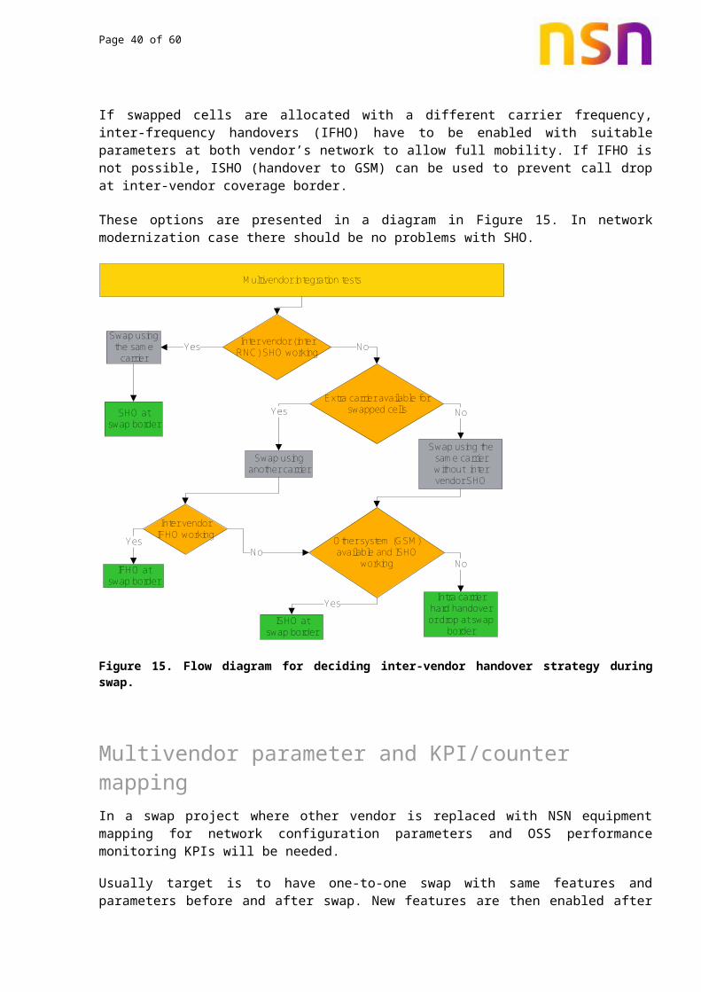
If swapped cells are allocated with a different carrier frequency, inter-frequency handovers (IFHO) have to be enabled with suitable parameters at both vendor’s network to allow full mobility. If IFHO is not possible, ISHO (handover to GSM) can be used to prevent call drop at inter-vendor coverage border.
These options are presented in a diagram in Figure 15. In network modernization case there should be no problems with SHO.

Page 32 of 47
Multivendor integration tests
Inter vendor (inter RNC) SHO working
Extra carrier available for swapped cells
Other system (GSM) available and ISHO
working
NoYesSwap using the same
carrier
Swap using another carrier
ISHO at swap border
Inter vendor IFHO working
Yes
YesSHO at swap border
Swap using the same carrier without inter vendor SHO
No
Intra carrier hard handover or drop at swap
border
NoIFHO at
swap border
YesNo
Figure 15. Flow diagram for deciding inter-vendor handover strategy during swap.
12. Multivendor parameter and KPI/counter mappingIn a swap project where other vendor is replaced with NSN equipment mapping for network configuration parameters and OSS performance monitoring KPIs will be needed.
Usually target is to have one-to-one swap with same features and parameters before and after swap. New features are then enabled after swap is completed and acceptance KPIs are met. Fully similar mapping is usually not possible due to implementation and parameter differences between the vendors. Therefore target is to have as close mapping as possible. It should be discussed with the customer that there may be some differences in some of the functionality.
Also available counters and their pegging to network events differ between different vendors. This causes some uncertainty to the OSS statistics when counter based performance delta between old and new network is measured.
Due to the counter differences it is recommended to use only some high level KPIs such as setup success rates and drop rates from OSS as acceptance KPIs, since they are usually quite well defined in all vendors’ networks implementation. More detailed and specific KPIs may not measure exactly same events and they difference in the KPI values may wrongly be thought to be due to the network performance.
To overcome the uncertainties in OSS bases KPIs in a vendor swap, drive test KPIs should always be collected and they should have the heaviest weight in the new network performance evaluation and comparison to the earlier performance.

Page 33 of 47
References to available KPI and parameter mapping between NSN and other vendors are collected to the following paragraphs.
12.1 BSS KPI and parameter mapping referencesAll multivendor related mapping references are collected to Multivendor folder in IMS-sharenet:
https://sharenet-ims.inside.nokiasolutionsandnetworks.com/Open/410911135
NPO CaMgmt GERAN Modernization folder is located to
https://sharenet-ims.inside.nokiasolutionsandnetworks.com/Open/403811279
Ericsson to NSN BSS KPI and parameter mapping tables can be found from
https://sharenet-ims.inside.nokiasolutionsandnetworks.com/livelink/livelink/overview/D431032683
https://sharenet-ims.inside.nokiasolutionsandnetworks.com/livelink/livelink/overview/D427793484
Huawei to NSN BSS KPI and parameter mapping tables can be found from
https://sharenet-ims.inside.nokiasolutionsandnetworks.com/livelink/livelink/overview/D426649378
https://sharenet-ims.inside.nokiasolutionsandnetworks.com/livelink/livelink/overview/D429739169
For other vendor mappings please see Multivendor folder in IMS and references to past projects in Chapter 13.
12.2 RAN KPI and parameter mapping referencesAll multivendor related mapping references are collected to Multivendor folder in IMS-sharenet:
https://sharenet-ims.inside.nokiasolutionsandnetworks.com/Open/410911135
NPO CaMgmt WCDMA Modernization folder is located to
https://sharenet-ims.inside.nokiasolutionsandnetworks.com/Open/400096872
Ericsson to NSN RAN KPI mapping tables can be found from
https://sharenet-ims.inside.nokiasolutionsandnetworks.com/livelink/livelink/overview/D425759283
Huawei to NSN RAN KPI and parameter mapping tables can be found from
https://sharenet-ims.inside.nokiasolutionsandnetworks.com/livelink/livelink/overview/D425332910

Page 34 of 47
https://sharenet-ims.inside.nokiasolutionsandnetworks.com/livelink/livelink/overview/D426651601
For other vendor mappings please see Multivendor folder in IMS and references to past projects in Chapter 13.
12.3 NSN default parametersNSN BSS parameter dictionary with default parameters can be found from
https://sharenet-ims.inside.nokiasolutionsandnetworks.com/livelink/livelink/overview/D428454034
NSN RAN parameter dictionary with default parameters can be found from
https://sharenet-ims.inside.nokiasolutionsandnetworks.com/livelink/livelink/overview/D419165584
and NPO recommended parameters for RAN optimization from
https://sharenet-ims.inside.nokiasolutionsandnetworks.com/livelink/livelink/overview/D419150667
NSN counter and parameter definitions are also included in the BSS/RAN Operation documents available from NOLS in pdf or NED format, see references 1 and 2.
All network parameters with default values in Excel or other formats can also be downloaded from PDDB
http://pddb.inside.nokiasolutionsandnetworks.com/pddb/login.do
13. Reference material from past projectsSwap support folder
https://sharenet-ims.inside.nokiasolutionsandnetworks.com/Open/382179624
contains links to nearly all IMS material related to network modernization and swaps.
General IMS folder for swap and modernization lessons learnt documents
https://sharenet-ims.inside.nokiasolutionsandnetworks.com/Open/382928792
Pre-sales information for several swap and modernization cases can be found from
https://sharenet-ims.inside.nokiasolutionsandnetworks.com/Open/369416358
Links to project material and lessons learnt slides of some past projects are in following chapters.

Page 35 of 47
13.1 BSS swap projectsEricsson to NSN swaps:
https://sharenet-ims.inside.nokiasolutionsandnetworks.com/Open/412585060
https://sharenet-ims.inside.nokiasolutionsandnetworks.com/Open/412571763
https://sharenet-ims.inside.nokiasolutionsandnetworks.com/Overview/D419716426
ALU to NSN swap:
https://sharenet-ims.inside.nokiasolutionsandnetworks.com/Overview/D358950572
https://sharenet-ims.inside.nokiasolutionsandnetworks.com/Overview/D372590825
Nortel to NSN swaps:
https://sharenet-ims.inside.nokiasolutionsandnetworks.com/Open/428093661
https://sharenet-ims.inside.nokiasolutionsandnetworks.com/Open/428068933
Motorola to NSN swaps:
https://sharenet-ims.inside.nokiasolutionsandnetworks.com/Overview/D412551394
https://sharenet-ims.inside.nokiasolutionsandnetworks.com/Overview/D419697334
Ex-Siemens to NSN modernizations:
https://sharenet-ims.inside.nokiasolutionsandnetworks.com/Overview/D427716508
https://sharenet-ims.inside.nokiasolutionsandnetworks.com/Overview/D420125396
https://sharenet-ims.inside.nokiasolutionsandnetworks.com/Overview/D383496707
For GEMINI project references, see
https://sharenet-ims.inside.nokiasolutionsandnetworks.com/Open/417140320
13.2 RAN swap projectsNEC to NSN swap:
https://sharenet-ims.inside.nokiasolutionsandnetworks.com/Open/414789669
ALU to NSN swap:
https://sharenet-ims.inside.nokiasolutionsandnetworks.com/Open/397985561

Page 36 of 47
References
1. NOLS / WCDMA RAN Operation document
https://online.portal.nokiasolutionsandnetworks.com/pic/com/nsn/extranet/pic/controller/productinfoview/pivdocumentation.do?productId=urn:nsn.com:mxpdm:133-001958
2. NOLS / GSM/EDGE BSS Operation document
https://online.portal.nokiasolutionsandnetworks.com/pic/com/nsn/extranet/pic/controller/productinfoview/pivdocumentation.do?productId=urn:nsn.com:mxpdm:133-001870
3. UTRAN and GERAN Parameter assessment and consistency check WI
https://sharenet-ims.inside.nokiasolutionsandnetworks.com/Open/D364148491
https://sharenet-ims.inside.nokiasolutionsandnetworks.com/Open/380101296
https://sharenet-ims.inside.nokiasolutionsandnetworks.com/Open/400432089
https://sharenet-ims.inside.nokiasolutionsandnetworks.com/Open/377623846
4. NetAct Plan Editor
https://sharenet-ims.inside.nokiasolutionsandnetworks.com/Open/390002169
5. UTRAN neighbour planning WI
https://sharenet-ims.inside.nokiasolutionsandnetworks.com/Open/393715157
6. UTRAN Neighbour assessment WI
https://sharenet-ims.inside.nokiasolutionsandnetworks.com/Download/380115223
https://sharenet-ims.inside.nokiasolutionsandnetworks.com/Open/397937092
7. Geran frequency and neighbour planning WI
https://sharenet-ims.inside.nokiasolutionsandnetworks.com/Open/392365775
https://sharenet-ims.inside.nokiasolutionsandnetworks.com/Open/394291362
8. UTRAN and GERAN Cluster tuning & acceptance guideline
https://sharenet-ims.inside.nokiasolutionsandnetworks.com/Open/D368977093
https://sharenet-ims.inside.nokiasolutionsandnetworks.com/Open/396547922
9. UTRAN and GERAN Performance analysis WI
https://sharenet-ims.inside.nokiasolutionsandnetworks.com/Open/374963768
https://sharenet-ims.inside.nokiasolutionsandnetworks.com/Open/390757710
https://sharenet-ims.inside.nokiasolutionsandnetworks.com/Open/398160832

Page 37 of 47
10. Jump portal
http://nop-i.nokiasolutionsandnetworks.com
11. Reporting suite reports
http://nop-i.nokiasolutionsandnetworks.com/reportmanager/htmlset.php?set=437&co=1&m=1&se=1
http://nop-i.nokiasolutionsandnetworks.com/reportmanager/htmlset.php?set=503&co=1&m=1&se=1
Page 38 of 47
AppendicesAppendix A – Templates for Technical Site Survey Summary
(TSSR) and site verification drive test
Appendix B – Example of a master plan for 2G and 3GTable 1, Master plan database fields (2G)
Database Field Description
BSC_Name
BSC_id
Site_id Unique key for collocated 900 and 1800 sectors on the same site or for all sectors on the same site
BCF_Name
BCF_id
BTS_Name
BTS_id BTS_id that will be generated during the creation
Direction Antenna Direction
Direction_Adj Antenna direction used in the NETACT adjacency tool
Sector Sector number
System GSM900 or GSM1800
Status Is BTS on air
Max_Config Maximum of TRXs in the actual sector
TRX_onair The number of TRX on air in the integration
TRX_installed Number of TRX's installed
Config e.g. 3+4+2
On_air Is sector on air or not
Planned_SWAP DateActual_SWAP Date

Page 39 of 47
SWAPped YES / NO
Foreigns_removed YES /NO
CI Cell ID
BCCHtype MBCCH/MBCCHC/MBCCB
SDCCH Number of full SDCCH timeslots
LAC_old Old vendor network LAC_id
LAC_new New LAC_id
NCC_old Old vendor network NCC
NCC_new New NCC (used temporary during the SWAP)
BCC Same BCC as old vendor network
BCCH BCCH frequency
Hopping Hopping ON, OFF
HSN Hopping sequence number
HYS Cell re-selection hysterisis
REO Cell re-selection offset
Indoor/Outdoor Site Type
Latitude Site coordinates for OSS
Longitude Site coordinates for OSS
Lat degrees OSS standard
Lat minutes OSS standard
Lat seconds OSS standard
Long degrees OSS standard
Long minutes OSS standard
Long seconds OSS standard
Page 40 of 47
Table 2, Master plan database fields (3G)
Database Field Description
Site Name Site Name (old and new are same)WBTS idOld RNC id Old system RNC id (and name if needed)New RNC id New system RNC id (and name if needed)WCEL idTRS IP addressSubnet MaskBTS IP addressRNC IP addressHSPA Enable /Disable
External equipment IP addresses
Columns for IP-addresses of remote electrical tilt, battery backup unit, location measurement unit, etc…
Transmission type Number of E1s or other specifiications
Transmission setting parameters Columns as neededCarriers in use Config On_air Live statusPlanned_swap Date DateActual_swap Date Date when confirmedswapped Yes/No, status changed after succesful swapForeigns_removed Yes/No, status changed after database deletionsRF-Parameters Tx powers, handover parameter sets, etc...… TRS-Parameters … Other Cell-, WBTS-, and Site-specific parameters as needed
… …

Page 41 of 47
Appendix C – Standard configurations for a 2G swap
IntroductionFollowing is a brief description explaining the standard antenna and TRX configurations that can be used during the customer's network swap with Flexi EDGE BTS.
Purpose The purpose of this document is to explain the possible configurations for the antenna line if the existing site configuration involves Radio Tunable Combiners (RTC) that can combine up to 5 TRXs. Changing from RTC to WBC combiners (2-way) can lead to different antenna and feeders requirements. The following are standard configurations, which will help in the assessment of additional feeders and cables.
Standard Flexi EDGE BTS configurationsFor more information about Flexi EDGE BTS and configurations, please see link to Flexi BTS documentation: https://sharenet-ims.inside.nokiasolutionsandnetworks.com/Open/375107768
Combining By-pass, 2way RX diversity, 2TRX /Cell
DuplexerLNA
Duplexer
LNA
Duplexer
LNA+Multi-
coupler
Duplexer
LNA+Multi-
coupler
DuplexerLNA
Duplexer
LNA
Duplexer
LNA+Multi-
coupler
Duplexer
DuplexerLNA
Duplexer
LNA
Duplexer
LNA+Multi-
coupler
Duplexer
LNA+Multi-
coupler
Flexi EDGE BTS Combining By-pass, 2-way RX diversity
Dual Duplexer Antennas
DualTRXExample:2 TRX/cell
TX1
RX1 MainDiv
Div
RX2 MainDiv
TX2
TX1
RX1 MainDiv
Div
RX2 MainDiv
TX2 2+2+2 (H*W*D):12HU x 19”x 400mmAntenna connectors
+47 dBm2.5 dB loss *
+44.5 dBm
Flexi EDGE BTS configuration

Page 42 of 47
2-way wideband combining, 2-way RX diversity, 4TRX/cell
Flexi EDGE BTS2-way Wideband Combining, 2-way RX diversity
Example: 4 TRX per CellWideband Combiners AntennasDual
Duplexer
DualTRXs
Duplexer
LNAD
uplexer
LNA
Duplexer
LNA+Multi-
couplerD
uplexer
LNA+Multi-
coupler
WBC
WBCTX1
RX1 MainDiv
DivRX2 Main
DivTX2
TX3
RX3 MainDiv
DivRX4 Main
DivTX4
Antenna connectors
This picture is not correctPhase feedback is not needed
(is used only for DPTRXs)
Flexi EDGE BTS configuration
4-way wideband combining, 2-way RX diversity, 8TRX/cell
DuplexerLNA
Duplexer
LNA
Duplexer
LNA+Multi-
coupler
Duplexer
LNA+Multi-
coupler
Flexi EDGE BTS 4-way Wideband Combining, 2-way RX diversity
Example:8 TRX/cell
WBCWBC
WBC
WBC
Wideband Combiners Dual Duplexer
AntennasDualTRXs
WBC
WBC
TX1RX1 Main
DivdivRX2 Main
DivTX2
TX1RX1 Main
DivdivRX2 Main
DivTX2TX3RX3 Main
DivdivRX4 Main
DivTX4
TX3RX3 Main
DivdivRX4 Main
DivTX4TX5RX5 Main
DivdivRX6 Main
DivTX6
TX5RX5 Main
DivdivRX6 Main
DivTX6TX7RX7 Main
DivdivRX8 Main
DivTX8
TX7RX7 Main
DivdivRX8 Main
DivTX8
Flexi EDGE BTS configuration
Page 43 of 47
Examples of antenna configuration conversions for SWAP:
CASE I: Three Vertical Polar antennas in sector and 4 or less TRXs
Existing : Before SWAP
RX TX RXD
Antenna configuration before swap
After : SWAP
TX/RX TX/RXD
Antenna configuration after swap
Note : Disconnect the TX antenna for the SWAP to NSN

Page 44 of 47
CASE II: Three vertical pole antennas and more than 6 TRXs in the sector
Existing : Before SWAP
RX TX RXD
Antenna configuration before swap
After : SWAP
Replace the three vertical pole antennas with two cross-polar antennas about 1m apart.
TX/RX TX/RXD
3m approx.
Antenna configuration after swap
Note : In case of Urban environment, the two X-Polar antennas need only be 1m apart.

Page 45 of 47
CASE III: Five or more TRXs in the sector and one cross-polar antenna
Existing : Before SWAP
TX/RX
Antenna configuration before swap
After : SWAP to NSN
TX/RX TX/RXD
1m approx.
Antenna configuration after swap
Note :
If the SWAP NSN configuration is 5/6 TRXS three feeders are required per sector.
If the SWAP NSN configuration is 7/8 TRXs four feeders are required per sector.
The existing cross-polar will be taken out and replaced by two new X-Polar Antennas
Page 46 of 47
CASE IV: More than four TRXs for G900 or more than four TRXs for 1800 and one dual band cross polar antenna per sector.
Existing : Before SWAP
TX/RX G900
TX/RX G1800
Antenna configuration before swap
After : SWAP to NSN
TX/RX G900
TX/RX G1800
TX/RX G900
TX/RX G1800
1m approx.
Antenna configuration after swap
Note :
This configuration is good for up to 8 TRXs for G900 and G1800 per sector.
Existing dual band antenna will be taken out and replaced by two new Kathrein dual band antennas.

Page 47 of 47
Appendix D – Antenna conversionIf the customer is using different types of antennas in there network e.g. Algon, Celwave, ADC., NSN is proposing to use only Kathrein antennas for SWAP, expansion and new sites. Attached is a file where some other antenna types are related to their Kathrein equivalent antennas. This correlation of antennas is based on the general antenna characteristics e.g. gain, horizontal and vertical beam width, and polarization. Only some 900 and 1800 MHz band antennas are included in the list.