3g long termevolution baseband processing with...
TRANSCRIPT

Hindawi Publishing CorporationInternational Journal of Digital Multimedia BroadcastingVolume 2009, Article ID 503130, 13 pagesdoi:10.1155/2009/503130
Research Article
3G Long Term Evolution Baseband Processing withApplication-Specific Processors
Perttu Salmela,1 Juho Antikainen,2 Teemu Pitkanen,1 Olli Silven,3 and Jarmo Takala1
1 Department of Computer Systems, Tampere University of Technology, P.O. Box 553, 33101 Tampere, Finland2 Centre for Wireless Communications, University of Oulu, P.O. Box 4500, 90014 Oulu, Finland3 Information Processing Laboratory, Department of Electrical and Information Engineering, University of Oulu, P.O. Box 4500,90014 Oulu, Finland
Correspondence should be addressed to Perttu Salmela, [email protected]
Received 13 November 2008; Accepted 6 January 2009
Recommended by Daniel Iancu
Data rates in the upcoming 3G long term evolution (LTE) standard will be manifold when compared to the current universalmobile telecommunications system. Implementing receivers conforming with the high-capacity transmission techniques ischallenging due to the complexity and computational requirements of algorithms. In this study, the software defined radio (SDR) istargeted and the four essential baseband functions of the 3G LTE receiver, namely, list sphere decoding, fast Fourier transform, QRdecomposition, and turbo decoding, are addressed and the functions are implemented as application specific processors (ASPs).As a result, the design space that describes the essential computational challenges of 3G LTE receivers is clarified and estimates ofarea, power, and interprocessor communication buffer requirements are presented.
Copyright © 2009 Perttu Salmela et al. This is an open access article distributed under the Creative Commons Attribution License,which permits unrestricted use, distribution, and reproduction in any medium, provided the original work is properly cited.
1. Introduction
The upcoming 3G long term evolution (LTE) standard willsupport data rates up to 100 Mbps [1]. Such a high data ratewill be achieved in 20 MHz bandwidth by using transmissiontechniques like orthogonal frequency division multiplexing(OFDM) [2], multiple-input multiple-output (MIMO) [3],that is, the use of multiple antennas, and an efficientforward error correction method, the turbo coding [4]. Asthese techniques are applied, the receiver needs to realizevery sophisticated algorithms. The design complexity ordifficulty of designing implementations of such algorithmscalls for flexible software-based solutions, that is, softwaredefined radio (SDR). On the other hand, the computationalcomplexity of algorithms advocates dedicated hardwareaccelerators for maximizing the performance. Thus, theimplementation technique of choice should possess thebenefits of both approaches.
High throughput and efficiency can be achieved withhighly parallel hardware accelerator which is designed forthe application in hand. As a drawback, designing is timeconsuming and any further changes can be difficult with
unprogrammable fixed hardware. Programmable processor-based implementations tend to suffer from a lower through-put, unused resources, and memory throughput bottlenecksbut they allow a shorter development time and higherflexibility due to the programmability. A solution, whichstrives to achieve the benefits of both hardware acceleratorsand processor-based implementations, is to use application-specific processors (ASPs) with highly parallel computingresources. With proper tools, ASPs can be designed andprogrammed rapidly, yet high throughput can be obtainedwith highly parallel computing resources. Flexibility andefficiency are obtained with accurate control at softwarelevel.
On the contrary to focusing on the implementationof solely one function, even a couple of interoperatingfunctions complicate the design. For example, the numberof clock domains and the most suitable clock frequenciesmust be determined for all the functions. In addition,there is always a tradeoff between area and throughput.Furthermore, even if the throughput is adequate, the delaycan be too long. Thus, the dimensions of the designspace include clock frequency, area, power, parallelism,

2 International Journal of Digital Multimedia Broadcasting
number of processors, clock domains, and so forth. Tofind answers to the multivariable and multiobjective designproblems, the design space must be explored by focusingon promising candidates, that is, design alternatives, andanalyzing them. Naturally, such analysis is far away fromevaluation of a fully functional system-on-chip (SoC) butit provides inevitable insight into the design problem inhand.
In this paper, efficient ASPs, whose performance rivalspure hardware implementations, are applied to the 3G LTEbaseband processing. The targeted essential and compu-tationally demanding baseband functions are list spheredecoding (LSD), fast Fourier transform (FFT), QR decom-position, and turbo decoding. Baseband functions are sep-arated from system level operations as the area and poweranalysis focuses on the core computations. The assistinginterprocessor communication (IPC) is analyzed in terms ofdata buffer requirements of ideal IPC links. The presentedwork forecasts how demanding the implementation of thesebaseband functions of the 3G LTE receiver would be, andwhat would be the number of logic gate equivalents (GE),power, number of processors, and IPC requirements withrealistic clock frequencies. The results also show how stronglyan efficient symbol detection method dominates the totalcomplexity.
The next section introduces some previous implementa-tion techniques and fundamentals of the addressed functionsand system. In Section 3, a high-level description of thetargeted receiver is presented. The applied ASP implemen-tations are presented in Section 4. Multiprocessing require-ments and complexity are analyzed in Section 5 before theconclusions.
2. Previous Work
The upcoming 3G LTE, MIMO-OFDM, and the maintransmission parameters are discussed in depth in [1].In [5], the fundamentals of MIMO communications,including the capacity gain, channel model, and receiveralgorithms are explained. As an example of the highpotential of MIMO-OFDM systems with sophisticatedsymbol detection, a 4 × 4 MIMO-OFDM system andmaximum likelihood (ML) detection achieves over 1 Gbpsthroughput in [6]. The MIMO-OFDM is applied also in4G telecommunications systems and WLANs. The entirebaseband processing chain of a 4G SDR is addressed in[7]. A hardware implementation of MIMO-OFDM sys-tem for WLANs is presented in [8] and implementationsof two vital functions, the matrix decomposition andsymbol detection with sphere decoder, are considered in[9].
Typical DSPs like TI’s C64x [10] are tempting candidatesfor baseband processing as they have parallel computingresources and special instructions suitable for many of therequired tasks. For example, the FFT can be computedwith an off-the-shelf library routine [11]. Alternatively, adedicated FFT processor can be used [12], and with FPGAs,off-the-shelf IP cores can be used for the FFT [13]. In this
paper, we have applied the FFT implementation presented in[14] for complexity and power estimations.
There are many alternative techniques and algorithmsfor QR decomposition. Since the MIMO receiver requiresa relatively small matrix, extensively parallel systolic arrayprocessors [15, 16] can be oversized solutions. The QRdecomposition requires the computation of a highly nonlin-ear operation, namely division by a norm or, alternatively,multiplication with an inverse of square root operation. Oneapproach is to carry out the computations in log2 domainas in [17]. A Nios processor with CORDIC accelerators onFPGA is used in [18]. In [19], a scalable architecture usingsquared Givens rotations is presented. In this paper, the QRdecomposition implemented in [20] has been applied.
In many practical MIMO systems, the ML symbol detec-tion can be too complex. Alternatively, for example, zeroforcing or linear minimum mean square error (LMMSE)principles can be applied [21]. In this paper, LSD isassumed as it approximates the ML detection with reducedcomputational complexity. There are several LSD variants. AK-best LSD is assumed in this study and in [22–24] wherearchitectures for the algorithm are presented. The K-bestLSD processor used in this paper is presented in detail in[25].
Turbo decoder can be implemented, for example, as acoprocessor of a DSP as in [26] or a hardware accelerator [27]or an ASP [28]. Naturally, there are variants of the algorithm,and the level of parallelism and clock frequency mainlydetermine the throughput. In this paper, a programmableturbo decoder presented in [29] is applied.
The ASP template, which is applied in this paper, usesthe transport triggered architecture (TTA) [30]. There existsmany multiprocessor systems applying TTA processors. In[31], a simple asynchronous communication link betweenTTA processors is enabled with units containing an FIFObuffer. TTA and LEON3 processors are connected with anAMBA bus in [32]. On the contrary to a shared bus, anetwork-on-chip approach has been applied in [33] wheretwo Coffee RISC processors, a TTA processor, and a sharedmemory are connected with a network. A bioinspiredmultiprocessor system is presented in [34, 35] where TTAprocessors are abstracted as cells of a biological system.In this paper, the IPC requirements of a multiprocessorsystem are analyzed, and an abstract multiprocessor systemusing shared memory banks as communication links isassumed.
Several inevitable building blocks for baseband process-ing are presented in the aforementioned references. On thecontrary to focusing solely on one particular function with-out practical motivation for the achieved throughput, wefocus on a baseband processing chain consisting of FFT, QRdecomposition, LSD, and turbo decoder and we derive theprocessing requirements from the 100 Mbps peak data rateof the upcoming 3G LTE systems. In this paper, we considerespecially the ASPs in [14, 20, 25, 29] and their applicabilityfor baseband processing. In order to obtain realistic esti-mates, the considered ASPs are resynthesized for the prevail-ing operating conditions, complexity, and power estimatesare given for a 3G LTE compliant system configuration.

International Journal of Digital Multimedia Broadcasting 3
3. System Model
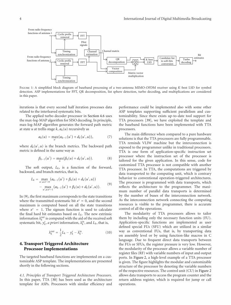
A high-level description of the targeted 2-antenna MIMO-OFDM receiver is presented in Figure 1. The input ports areconnected to radio-frequency functions of the receiver. Thefunctional block diagram is only a high-level model as itdoes not suggest how the functions should be mapped tothe processors nor it does not suggest how data is passedbetween the functions and whether the data vectors haveserial or parallel presentations. In the following, the targetedtransmission techniques are presented briefly.
3.1. Orthogonal Frequency Division Multiplexing. OFDMuses the frequency spectrum efficiently as the used frequencyband is divided into several orthogonal subcarriers. OFDMuses the FFT and inverse FFT (IFFT) for efficient conversionsbetween the time and frequency domains. The time domainsignal is generated in the transmitter side with inversetransform
XT = IFFT(XF), (1)
that is, data belonging to several parallel subcarriers is fedto the IFFT. In the receiver side, parallel subcarriers, XF, areextracted from the time domain signal XT with
XF = FFT(XT). (2)
To alleviate timing synchronization, additional cyclic prefixis inserted to the signal. The channel estimation can bealleviated with pilot symbols.
In the receiver side, distortion of the channel can beequalized conveniently in frequency domain by multiplyingthe received symbols with equalizing factors. Before the FFT,the cyclic prefix must be removed from the signal, and timingsynchronization is responsible for feeding the time domainsignal, whose length equals the FFT length, with correcttiming offset to the FFT block.
3.2. Multiple-Input Multiple-Output. In a spatial multiplex-ing MIMO system, multiple antennas are used to transmitindependent data streams. Spatial multiplexing gain, thatis, increase in capacity, is proportional to the numberof antennas and it does not require extra power norbandwidth. Two transmit and receive antennas are a highlyprobable configuration for the first 3G LTE systems, sincea higher number of antennas increases the computationalrequirements of symbol detection significantly.
Computational complexity of ML detection of trans-mitted symbols depends exponentially on the number ofspatial channels. Therefore, even with a modest number ofantennas, simpler approximative methods must be used. Theusage of list sphere decoding algorithms is tempting as theycan achieve higher performance than LMMSE [36], eventhough they are computationally demanding. The spheredetector restricts the search space by evaluating only thesymbols inside the sphere centered in the received symbol.In the system model in Figure 1, K-best LSD is assumed. TheK-best LSD operates by gradually increasing the dimension
of the symbol vector. At each level, a list of the K best partialsolutions is selected for continued processing.
In principle, an MIMO system with a complex-valuedchannel matrix, H, noise vector, n, transmitted symbol, s,and received symbol, y, can be described with
y = Hs + n. (3)
The number of receive and transmit antennas equals thenumbers of rows and columns of H, respectively. Thetransmitted symbol s′ can be estimated by ML detection bysolving
s′ = arg mins
∥∥y −Hs
∥∥2
, (4)
which gives the optimal result. However, solving (4) isintractable with multiple antennas and large constellations.
Instead of solving (4), the symbol estimation can besimplified by using QR decomposition of H. With thispractice, the computational complexity is lowered. Instead ofML detection, a substitute
s′ = arg mins
∥∥y′ − Rs∥∥2
where y′ = QHy (5)
is used. As the R is in upper triangular form, approxi-mation of s′ is computationally simpler with the aid of(5). The simplified approximation is based on computingthe Euclidean distance in (5) by gradually increasing thedimensions of the symbol vector. Basically, there will bepartial solutions which are too far away from the receivedsymbols and when such partial solutions are discarded, thesearch space is efficiently limited. The K-best LSD applies theaforementioned principles by maintaining a K-length list ofthe best partial solutions found so far.
3.3. Forward Error Correction. The function of the for-ward error correction is to introduce redundancy in thetransmitted signal in order to alleviate error detection andcorrection. In 3G LTE, a similar turbo coding as in thecontemporary 3G systems will be used. The only differenceis the definition of the interleaving function [37, 38]. Thenew interleaving function covers longer code blocks andit is simpler to implement than the contemporary 3Ginterleaving. Naturally, the longer code block size affects thememory requirements.
Turbo decoding is an iterative process, which runs asoft-in soft-out (SISO) component decoder several times.The arguments of the component decoder are extrinsicinformation λin, systematic bit, ys, and parity bit vector, yp.As a result, it generates new extrinsic information, λout, andsoft bit estimate vectors, L, that is,
(λout, L
) = fSISO(λin, ys, yp
). (6)
The a posteriori information is generated on the previoushalf iteration, and used as a priori information on thenext half iteration. The information exchange takes place bypassing the extrinsic information between the componentdecoder processes. The main difference between the half
4 International Journal of Digital Multimedia Broadcasting
K-bestLSD
Cyclic prefixremoval
Timingsynchronization
Cyclic prefixremoval
Channelestimation
Timingsynchronization
Matrix-vector
QRdecomposition
Vectorcomposition
Pilotsignals
Candidate listto soft-bitsconversion
Turbodecoding
Bitestimates
From radio frequencyfunctions of antenna 1
functions of antenna 2
From radio frequency
FFT
FFT
Channel matrix
multiplication
Figure 1: A simplified block diagram of baseband processing of a two-antenna MIMO-OFDM receiver using K-best LSD for symboldetection. ASP implementations for FFT, QR decomposition, list sphere detection, turbo decoding, and multiplications are consideredin this paper.
iterations is that every second half iteration processes datarelated to the interleaved systematic bits.
The applied turbo decoder processor in Section 4.6 usesthe max-log-MAP algorithm for SISO decoding. In principle,max-log-MAP algorithm generates the forward path metricat state u at trellis stage k, αk(u) recursively as
αk(u) = maxu′
(αk−1
(u′)
+ dk(u′,u
)), (7)
where dk(u′,u) is the branch metrics. The backward pathmetric is defined in the same way as
βk−1(u′) = max
u
(βk(u) + dk
(u′,u
)). (8)
The soft output, Lk, is a function of the forward,backward, and branch metrics, that is,
Lk = maxu′,u:xs=0
(αk−1
(u′)
+ βk(u) + dk(u′,u
))
− maxu′,u:xs=1
(αk−1
(u′)
+ βk(u) + dk(u′,u
)).
(9)
In (9), the first maximum corresponds to the state transitionswhere the transmitted systematic bit xs = 0, and the secondmaximum is computed based on all the state transitionswhere xs = 1. The signum function is used to calculatethe final hard bit estimates based on Lk. The new extrinsicinformation λout
k is computed with the aid of the received softsystematic bit, ysk, a priori information, λin
k , and Lk, that is,
λoutk = 1
2Lk − ysk − λin
k . (10)
4. Transport Triggered ArchitectureProcessor Implementations
The targeted baseband functions are implemented on a cus-tomizable ASP template. The implementations are presentedshortly in the following sections.
4.1. Principles of Transport Triggered Architecture Processors.In this paper, TTA [30] has been used as the architecturetemplate for ASPs. Processors with similar efficiency and
performance could be implemented also with some otherASP templates supporting sufficient parallelism and cus-tomizability. Since there exists up-to-date tool support forTTA processors [39], we have exploited the template andthe baseband functions have been implemented with TTAprocessors.
The main difference when compared to a pure hardwaresolutions is that the TTA processors are fully programmable.TTA reminds VLIW machine but the interconnection isexposed to the programmer unlike in traditional processors.TTA is one form of application-specific instruction setprocessor where the instruction set of the processor istailored for the given application. In this sense, code forcustomized TTA processor is not compatible with anotherTTA processor. In TTA, the computations are triggered bydata transported to the computing unit, which is contrarybehavior to conventional operation-triggered architectures.The processor is programmed with data transports, whichreflects the architecture to the programmer. The maxi-mum number of parallel data transports is determinedby the number of buses of the interconnection network.As the interconnection network connecting the computingresources is visible to the programmer, there is accuratecontrol of all the operations.
The modularity of TTA processors allows to tailorthem by including only the necessary function units (FU).Application-specific functions are implemented as userdefined special FUs (SFU) which are utilized in a similarway as conventional FUs, that is, by transporting dataon assembly level or by using function-like macros in Clanguage. Due to frequent direct data transports betweenthe FUs or SFUs, the register pressure is very low. However,the modularity of the processor allows a variable number ofregister files (RF) with variable numbers of input and outputports. In Figure 2, a high-level example of a TTA processoris given. The figure highlights the modular and customizablestructure of the processor by denoting the variable numbersof the respective resources. The control unit (CU) in Figure 2allows data transports to access the program counter and thereturn address register, which is required for jump or calloperations.

International Journal of Digital Multimedia Broadcasting 5
The load on the buses of the interconnection networkcan be lowered by excluding the unnecessary connectionsif the work load of the processor is known beforehand. Inthis case, the targeted application program determines whichconnections are used. Typically, one application requiresonly a fraction of all the possible connections between thecomputing resources. If any other application is run on thesame processor, it must be able to use the same connections.As a consequence of the limited connectivity and loweredload on the buses, the maximum clock frequency of theinterconnection network is raised.
4.2. Multiprocessor Systems with TTA Processors. There existsmany multiprocessor systems applying TTA processors aslisted in Section 2. However, the required number of pro-cessors for baseband processing in Section 5 is far higherthan the number of processors in [31–33]. In additionto the bioinspired abstraction of multiple TTA processors[34, 35], multiple processors could be also abstracted as ahierarchical structure where the SFUs would be comprised ofTTA subprocessors. Another way would be to combine all theTTA processors to a set of loosely connected clusters inside asingle TTA processor. However, assembly programming sucha processor would be error prone due to the extremely longinstruction word and the scheme would limit the controlflow of the clusters very strictly to a single combined flow.Regardless of the applied structure of the multiprocessorsystem, generating and controlling a multiprocessor systemconsisting of dozens of processors would be a demandingtask.
Since it would be uneconomical to produce results ofcomputations faster than they can be transferred to the nextstage, shared memory banks or RFs running with the sameclock frequency, fi, as the processors must be assumed forthe IPC at the lowest level. Fortunately, the applied TTAprocessor template has flexible memory interfaces, whichcan simplify the IPC. For example, simple point-to-pointconnections between two processors could be implementedwith an SFU interfacing a shared single- or dual-portmemory. Furthermore, if complex address generation orbank selection is required, it can be included to the same SFU,which slightly raises the abstraction level of the IPC visible tothe programmer. Such an incorporation of all the memoryrelated logic to the same unit could enable a seamless IPC.
4.3. FFT Processor. The applied FFT TTA processor ispresented in detail in [14]. The processor implements mixed-radix FFT consisting of radix-2 and radix-4 computationsand it supports several power-of-two transform sizes. It has11 RFs containing 25 general-purpose registers and threeBoolean registers, 17 buses in the interconnect network, aconventional adder, a comparison unit, and two-load/storeunits. The main computations are carried out with thefollowing SFUs.
Complex Adder Unit. It supports four different summationscomposed of four alternative operands.
Complex Multiplier. It alleviates the butterfly operation withfour real multipliers and two real adders.
Address Generator Unit . It generates two addresses withbitwise reversal and rotation operations.
Coefficient Generator. It generates the twiddle factors insteadof loading them from a memory.
The processor applies a complex-valued number pre-sentation where the real and imaginary parts both take 16bits. Data is stored in single-port memory banks and thekernel loop applies the principles of software pipelining.Code compression is applied to enhance the code density andlower the power consumption.
4.4. QR Decomposition Processor. The QR TTA processorpresented in [20] is based on the modified Gram-Schmidtalgorithm [40]. With complex-valued arithmetic units theprocessor can compute equally well both the complex- andreal-valued decompositions. The only conventional unitsof the processor are the two-load/store units and an RFconsisting of five general purpose registers. The interconnec-tion network contains seven buses. The applied SFUs are asfollows.
Complex Adder/Subtractor Unit. It is for native complex-valued computations.
Complex Multiplier Unit. It can optionally conjugate theother input. The conjugation is required for the computationof the real-valued norm.
1/√x unit is for a fast estimation of the highly nonlinear
function. The function is used in the QR decomposition toavoid division operations.
As the processor has a bit accurate complex multiplier, itcan be used also for other tasks where the accuracy of 16-bitfixed-point number system is sufficient. The 1/
√x unit and
the multiplier can be used also for computation of squareroot as x(1/
√x) = √x.
4.5. K-Best LSD Processor. The LSD TTA processor in[25] generates a 16-element list of candidate solutions toapproximate the transmitted symbol s′ in (5). The processoruses 16-bit arithmetic and it is targeted for 2 × 2 antennasand 64-quadrature amplitude modulation (QAM). Insteadof 2 × 2 complex-valued matrix, a real-valued matrixwith doubled dimensions is processed. Therefore, a real-valued 4 × 4 QR decomposition is required for the LSD.The interconnection network is very sparse and contains16 buses. The arithmetic operations are computed withtwo addition units, a subtraction unit, a multiplier, anda squaring unit. The following SFUs are targeted for theapplied K-best algorithm.
Insertion Sorter Unit. It sorts a list of 16 samples accordingto the partial Euclidean distances (PED). Internally, the list

6 International Journal of Digital Multimedia Broadcasting
Datamemory
Load/store units andmemory interfaces
RF
LSU
FU
SFU
Function
Register
units
functionunits
CU
Control unitprogram
counter
Special
connectionsthe buses
files
customized accordingapplication
Sockets, whose
Buses
Interconnection network, whichis visible to the programmer
· · ·
· · ·
· · ·
· · ·
· · ·
· · ·
· · ·
· · ·
· · ·
· · ·
· · ·· · ·
with
withcan be
to the
Figure 2: TTA processors consist of a CU and variable number of FUs, SFUs, RFs, and LSUs. Unused connections between the resources canbe excluded from the interconnection network.
is kept in a shift register and the new value is inserted to theregister pointed by comparison logic.
PED Extractor Unit. It extracts the PED from the internalstorage format, that is, the unit accesses bits by hardwiring.
Multiplexer and Look-Up-Table Unit. It consists of a mul-tiplexer selecting the bits, which index the look-up-table.In principle, the unit converts a bit pattern to fixed-pointformat.
Storage Format Composer Unit. It composes a 28-bit wordconsisting of symbol information and the correspondingPED.
There are three RFs of sizes 16, 10, and 4 registers. On thecontrary to conventional processors, the LSD TTA processordoes not have load/store units nor data memory, since thereis no need for accessing large arrays. The input data is passedvia two RFs and the results of the computations are availablein the registers of the insertion sorter SFU.
4.6. Turbo Decoder Processor. The turbo decoder TTA pro-cessor is presented in [29]. It has a sparsely connectedinterconnect network of 30 buses and the high numberof buses is a consequence of high parallelism. The onlyconventional FUs are the addition and comparison units.There are only two RFs, both of them containing one generalpurpose register. As there are not many conventional FUs, theapplied max-log-MAP algorithm is computed solely with thefollowing SFUs.
Control Unit. It generates a control word which is used as anargument to all the other SFUs.
Address Generator. It generates addresses for accessing thebranch metric buffer.
Forward Process Unit. It computes forward path metricsaccording to (7).
Backward Process Unit. It computes backward path metricsas defined in (8) and extrinsic information and soft outputbit estimates according to (10) and (9), respectively.
Branch Metric Generator. It generates and buffers the branchmetrics for the forward and backward processes.
The turbo decoder TTA processor applies high paral-lelism as it processes one trellis stage in 1.016 clock cycles onaverage, that is, both forward and backward path metrics arecomputed in one clock cycle. Such a high parallelism requiresalso a high memory throughput. Therefore, the processordoes not have conventional load/store units. Instead, theSFUs access memory interfaces of the processor directly. As(7)–(10) indicate, the main computations in the SFUs arecarried out with basic arithmetic, add-compare-select, andmaximum operations. The processor includes memory bankselection, address generation, and access buffer logic to allowparallel interleaved accesses of the extrinsic information withfour-single-port memory banks. The interleaving function isexcluded from the processor and it is accessed via externalinterface of the processor.
5. Processing Requirements and Complexity
The number of processors, their total area and memoryrequirements, and interprocessor communication require-ments are derived from the targeted 100 Mbps throughput.

International Journal of Digital Multimedia Broadcasting 7
5.1. Time and Throughput Requirements. There are sevenOFDM symbols per transmit antenna in 0.5 millisecondtime frame in 3G LTE downlink. Thus, the processing timerequirement TFFT = 0.5 millisecond/7 = 71 microsecondsincludes also the additional time contributed by the cyclicprefix of the OFDM symbol. The FFT must be computed forboth antennas.
The QR decomposition must be processed in the coher-ence time, Tcoh, of the channel. If bullet train speed vr =500 km/h is assumed for the receiver, the coherence time isTcoh = c/(Fvr) = 0.9 millisecond where c is the speed oflight and F = 2.4 GHz is the carrier frequency. However,with a more rapidly varying channel, the QR decompositionmust be computed more frequently, that is, shorter Tcoh
must be used in (12). A single QR decomposition combinesinformation from all the antennas. In other words, the matrixand vector sizes of the QR decomposition depend on thenumber of antennas.
The LSD must be computed for each subcarrier. So, thetime requirement equals to the time requirement of the FFT.However, even if the maximum length of the FFT is 2048,only 1201 subcarriers are in use. A single LSD processesthe signals of both antennas, that is, it outputs estimates ofsymbols transmitted from both antennas.
Since the turbo decoder processes soft bits instead ofQAM symbols, it is meaningful to express throughput as datarate. The throughput requirement of turbo decoding equalsthe maximum data rate of 100 Mbps. Naturally, with coderate R = 1/2 and 64-QAM symbols, the data rate on the LSDside is 200 Mbps and symbol rate 33.3 Msps.
5.2. Required Number of Clock Cycles. The FFT TTA pro-cessor in [14] takes 12332 clock cycles for the 2048-pointtransform and the transform must be computed for bothantennas. So, the required clock cycles of the FFT task are
CFFT = 2× 12332 = 24664. (11)
The QR decomposition algorithm is of order O(n3) andthe QR decomposition TTA processor in [20] takes 139 clockcycles for a 4× 4 matrix. The dimensions of the decomposedmatrix are doubled, since the LSD TTA processor appliesreal-valued computation. Since the Q matrix is the argumentof matrix-vector product in (5), the products are mappedto the same processor. The products must be computedcontinuously for each received symbol vector, but the QRdecomposition only once in the coherence time. So, theaverage number of clock cycles in TFFT time period, for bothcomputations is approximately
CQR avg = 1201×(
139×(TFFT
Tcoh
)+ 16
)= 32386, (12)
where 4 × 4 matrix multiplication takes 16 clock cycles.Naturally, with more rapidly varying channel, the CQR avg
increases as the Tcoh must be decreased. The products takeapproximately 59% of the CQR avg. The maximum numberof clock cycles is spent when the decomposition of a newchannel matrix is computed for each subcarrier, that is,
CQR = 1201× (139 + 16) = 186155. (13)
0
1
2
3
4
5
6×10⁵
CLSD
CTurbo
CQR avgCFFT
Figure 3: Required number of clock cycles of the processing tasksin TFFT = 71 microseconds time frame.
The average number of clock cycles, CQR avg, is only 17% ofthe maximum, CQR.
The LSD TTA processor in [25] takes 441 clock cyclesfor processing one symbol vector. Thus, in TFFT time periodthe number of required clock cycles for the LSD, CLSD, isapproximately
CLSD = 1201× 441 = 529641. (14)
Fortunately, the LSD can be parallelized among the subcarri-ers.
In order to compare turbo decoding with the otherbaseband functions, the clock cycles of turbo decoding mustbe normalized to clock cycles, CTurbo, taken in TFFT timeframe. The turbo decoder TTA processor in [29] takes 1.016clock cycles per trellis stage processed in half iteration.With six iterations, each trellis stage is processed 12 times.Therefore,
CTurbo = TFFT × 100× 106 × 12× 1.016 = 86563, (15)
where the first multiplications TFFT × 100 × 106 expresshow many bits are processed in TFFT. Turbo decoding canbe parallelized to several processors with block-by-blockpipelining where each processor decodes a code block of itsown independently.
The required number of clock cycles of all the four func-tions are illustrated in Figure 3. The figure shows clearly howthe LSD dominates the computation load. Obviously, therequirements cannot be met with single-processor systemswith currently achievable clock frequencies.
5.3. Number of Processors. The required minimum numberof processor is determined by the throughput per processor,clock frequency, fi, and parallelization scheme of the targetedfunctions. If a task i can be parallelized to several processorsand the throughput is directly proportional to the numberof processors, then the minimum required number of

8 International Journal of Digital Multimedia Broadcasting
processors, Pi, of the task i taking Ci clock cycles in timeframe TFFT is
Pi =⌈(Ci/TFFT
)
fi
⌉
. (16)
The utilization, Ui, of the processor, Pi, dedicated to task itells how efficiently the computing resources are used. It canbe defined in a similar way as
Ui = Ci(PiTFFT fi
) . (17)
Naturally, 100 × (1 − Ui) tells how many percent of thetime the processor Pi idles. For the QR decomposition andmatrix-vector product task, the average number of clockcycles, CQR avg, is used to calculate the minimum number ofprocessors and utilization. The total utilization of the wholeprocessing chain can be computed as
U =∑
i∈Stasks
Ci(TFFT
∑i∈Stasks
Pi fi) , (18)
where the sums are computed for all the elements of the taskset Stasks = {FFT, QR avg, LSD, Turbo}. The total utilizationin (18) expresses the ratio between the required executioncycles of all the tasks and the available execution cycles of allthe processors.
5.4. Delay. The delay of a task depends on the maximum sizeof the processed data vector and the scheduling. Except forthe first half iteration, the turbo decoder requires that thewhole code block is received before decoding. The maximumcode block length is 6144 [37], which is about 20% longerthan in the current 3G systems. With code rate R = 1/2,the required number of soft bits is naturally 2 × 6144 =12288. For two OFDM symbols, the LSD generates symbolcandidate lists, which can be converted to 2 × 1201 × 6 =14412 soft bit estimates with 64-QAM (6 bits per symbol).Since the number of soft bits exceeds the required number forthe maximum code block length, the analysis of the delay ofFFT and LSD can be limited to the processing of two OFDMsymbols.
With at maximum two processors, the delay of the FFT issimply
DFFT = CFFT(PFFT fFFT
) , PFFT ∈ {1, 2}, (19)
and in a similar way the delay of the LSD is
DLSD = CLSD(PLSD fLSD
) , (20)
where PLSD ∈ {1, 2, . . . , 1201} as the LSD can be parallelizedamong the subcarriers. The QR decomposition processorhas two tasks, the QR decomposition and the matrix-vectorproducts, of which the QR decomposition is computed onlyonce in the coherence time, tcoh = 0.9 millisecond. Thus, theworst-case delay when both tasks are computed is
DQR =CQR(
PQR fQR) , (21)
0.94
0.95
0.96
0.97
0.98
160 180 200 220 240 260
(a)
0.75
0.8
0.85
0.9
0.95
160 180 200 220 240 260
(b)
40
45
50
55
60
160 180 200 220 240 260
(c)
Figure 4: Configurations as a function of fi with single clockdomain: (a) total utilization, (b) total delay in millisecond, (c) thenumber of processors. The x-axis denotes fi in MHz.
where PQR ∈ {1, 2, . . . , 1201} as the decompositions andmultiplications can be parallelized among the subcarriers.For an average delay,CQR avg can be used in a similar way. Thedelay of turbo decoding is determined by the maximum codeblock size, 6144. Thus, the delay with six turbo iterations is
DTurbo = 6144× 6× 2× 1.016fTurbo
, (22)
where processing one trellis stage with the turbo decoderTTA processor takes on average 1.016 clock cycles. Distribut-ing the turbo decoding to several processors with block-by-block pipelining would affect only the throughput but notthe delay and, therefore, the number of processors is omittedfrom (22).
5.5. TTA Processor Configurations as Function of ClockFrequency. Utilization, delay, and number of processors areanalyzed in Figure 4 as functions of clock frequency. Thetotal utilization in Figure 4(a) shows that the utilization isalways greater than 0.93 in the explored clock frequencyrange. High utilization can be obtained easily, since theLSD dominates the computational load and it can beparallelized with very fine granularity. In other words, sincethe utilization of the LSD task is always high, also theutilization of the whole processing chain is relatively high.The peaks in the utilization occur, when the number ofprocessors of some task can be decremented. In that case,the utilization grows. On the contrary, if the number ofprocessors remains untouched and the clock frequency is

International Journal of Digital Multimedia Broadcasting 9
Table 1: The baseband processing chain with TTA processors, 2× 2 antennas, 1201 subcarriers, 64-QAM, 6144-length turbo code block, listlength K = 16, data rate 100 Mbps.
Clk. freq.fi (MHz)
Task iNo. of procs.
PiUtil. Ui
DelayDi (ms)
Area(kGE)
Area×Pi
Power est.(mW)
Power est.×Pi ×Ui
Tech. (μm) Ref.
250 FFT 2 0.69 0.049 30.5 61.0 36.3 50.1 0.13 [14]
250 Turbo dec. 5 0.98 0.300 35.1 175.5 50.8 248.9 0.13 [29]
250 QR & prod. 2 0.91 0.372 17.7 35.4 13.1 23.8 0.13 [20]
250 LSD 30 0.99 0.071 23.6 708.0 20.8 617.8 0.13 [25]
Total 39 0.97 0.792 979.9 940.6
Table 2: An example baseband processing chain with 2 × 2 antennas, 1201 subcarriers, 16-QAM, 4804-length turbo code block, data rate68 Mbps.
Clk. freq.fi (MHz)
Task iNo. of units
PiUtil. Ui
DelayDi (ms)
Area(kGE)
Area×Pi
Power est.(mW)
Power est.×Pi ×Ui
Tech. (μm) Ref.
600 & 300 FFT & Turbo 5 0.36 0.396 — — 718 1303 0.13 [26]
223 QR 1 0.29 0.259 198 198 — — 0.13 [9]
213Sphere
Decoder1 0.92 0.065 61 61 — — 0.13 [9]
Total 7 0.38 0.720 — —
increased the utilization decreases. The discontinuations ofdelay in Figure 4(b) originate from the same phenomenon.The greatest discontinuation at 229 MHz takes place as theQR decomposition is mapped from three to two processors.The number of processors in Figure 4(c) decreases quitesteadily, since it is dominated by the LSD task, which requiresthe largest number of processors.
5.6. Analysis. An example configuration of TTA processor-based baseband processing chain is presented in Table 1.A single clock domain with fi = 250 MHz is appliedand the processors have been synthesized with 0.13 μmtechnology for obtaining complexity and power estimates.The area and power estimates exclude the memories. Thepower estimates are scaled with the number of respectiveprocessors and their utilization in the ninth column ofTable 1. The results in Table 1 show that since the LSD tasktakes only 441 clock cycles per subcarrier and it can becomputed for each subcarrier independently, the task canbe easily divided among several processors to achieve a highutilization. On the contrary, it is more difficult to obtainvery high utilization for both the FFT and the QR processorswith the same clock frequency, as the granularity of the tasksis more coarse. As a second remark, the delay of the QRdecomposition is long when compared to other functions,even though the other functions are more complex. However,the QR decomposition must be computed only once in thecoherence time tcoh = 0.9 millisecond, that is, the delay inTable 1 is the worst case delay. On average, the delay of theQR decomposition and the matrix-vector products is only17% of the delay in Table 1.
In principle, the FFT and QR tasks could be mapped tothe same processor. The processor should be formed as a
hybrid of both processors in this case. Since both functionsrequire complex arithmetic, the same resources could beshared efficiently. With fi = 402 MHz, both tasks couldbe mapped to two hybrid FFT/QR TTA processors and autilization, UFFT/QR = 1.00, would be obtained.
Mapping the turbo decoding and some other function tothe same processor could not benefit as much from sharingthe resources, since the turbo decoding requires mostlyreal-valued add-compare-select operations. Shortening thedelay of the turbo decoding is difficult for two reasons.Firstly, turbo decoding is an iterative process where theprevious iteration must be finished before the next one canbegin. Secondly, the component decoder applying the radix-2 algorithm processes at maximum one trellis stage in oneclock cycle. The next path metrics cannot be computedaccording to (7) and (8) before the previous ones arecomputed. For these reasons, increasing the clock frequencyor applying the radix-4 algorithm are the only ways toshorten the delay of the turbo decoding task in Table 1.
To illustrate more deeply the computational require-ments of the baseband processing, example configurationsconsisting of other implementations are shown in Tables 2–4. As the respective implementations in Tables 2–4 are notnecessarily targeted to the 3G LTE system or they are nottargeted to operate among each other, the Tables 1–4 shouldbe not considered as comparisons of TTA processors andother implementations. Instead, the tables show indicativeexample configurations of baseband processing chains.
For some implementations, all the required informationis not available or it is given with different units. Thearea is reported if it has been given as the GEs. For someimplementations, the performance data is not availablefor the targeted configuration of 2048-length FFT, 2 × 2

10 International Journal of Digital Multimedia Broadcasting
Table 3: An example baseband processing chain with 4 × 4 antennas, 601 subcarriers, 16-QAM, 4808-length turbo code block, list lengthK = 10, data rate 68 Mbps.
Clk. freq.fi (MHz)
Task iNo. of units
PiUtil. Ui
DelayDi (ms)
Area(kGE)
Area×Pi
Power est.(mW)
Power est.×Pi ×Ui
Tech. (μm) Ref.
45 FFT 2 0.63 0.045 — — 480 608.45 0.35 [12]
400 Turbo dec. 5 0.82 0.288 64.1 320.5 — — 0.065 [28]
80 QR 1 0.54 0.489 — — — — 0.25 [8]
50 LSD 2 0.85 0.060 132 264 — — 0.13 [23]
Total 10 0.80 0.882 — —
Table 4: Requirements of 4G baseband processing chain for100 Mbps data rate [7].
Assumed clk.freq (MHz)
Task i [7] MCycles/s [7] Assumed no.of Procs. Pi
Util. Ui
360 FFT 360 1 1.00
240 STBC 240 1 1.00
385 LDPC 7700 20 1.00
Total 8300 22 1.00
antennas, 64-QAM, and list length 16. For this reason,alternative MIMO-OFDM configurations with lower datarate, 68 Mbps, have been used. Shorter code blocks areassumed for turbo coding in Tables 2 and 3. With shortercode blocks, the delay of the FFT can be limited to processingone OFDM symbol per each antenna.
In the configuration in Table 2, hardware implementa-tions presented in [9] are used for the matrix decompositionand symbol detection. For the FFT and turbo decodingthe TI’s C6416 DSP has been applied as it can computethe FFT with an efficient software library routine andit includes a turbo coprocessor which runs with halvedclock frequency. Since the core DSP and turbo coprocessorare mapped to the same device, the number of requiredprocessors is determined by the more dominating task,that is, turbo decoding. The idling of the DSP core whileturbo decoding is taken into account when the utilization inTable 2 is calculated, and therefore, the utilization is low inTable 2 but still several processors are required. The hardwareimplementations for QR and symbol detection in Table 2 aretargeted for MIMO-OFDM systems [9]. However, the spheredetector applies a different algorithm than the K-best LSDwhich is used in TTA processor implementations.
In Table 3 a 1024-point FFT is applied. The applied turbodecoder processor supports also Viterbi decoding. The listlength of the K-best LSD is 10 symbols. In principle, acomplex-valued K-best LSD with 64-QAM, 2 antennas, andK = 16 must process 64 + 16 × 64 = 1088 nodes andwith 16-QAM, 4 antennas, and K = 10 it must process16+10×16+10×16+10×16 = 496 nodes during the symboldetection. Thus, the processing requirements of differentsymbol detectors can be characterized by the number ofvisited nodes during a tree traversal of the algorithm. Theapplied QR decomposition hardware accelerator is presented
Table 5: Area of the core processor without memories and datamemory requirements of the processors.
TTAprocessor
Clk. freq.fi (MHz)
Area(kGE)
Data memory requirements(kbits)
FFT 250 30.565.5 divided into 2single-port memory banks
QR 250 17.7 1.5 dual-port memory
LSD 250 23.6 0.0 (uses only registers)
Turbodecoder
250 35.1281.7 divided into 16single-port memory banks
Table 6: Additional buffer memory requirements for seamless IPC.
IPC buffer Memory (words) Memory (kbits)
FFT: next input 2× 2048 131.1
FFT: prev. result 2× 2048 131.1
QR: R, QHy 1201× (10 + 4) 538.0
QR: prev. results 1201× (10 + 4) 538.0
Turbo: next input 3× 6114 + 12 128.5
in [8] as a part of MIMO-OFDM transceiver for WLANs.The decomposition takes 65 clock cycles for 4× 4 matrix.
In Table 3, the workload of 4G baseband processingwith 100 Mbps is presented in terms of required executioncycles on an SODA architecture [7]. For each task a realisticclock frequency is assumed and the tasks are divided toseparate processors. Furthermore, it is assumed that theLDPC error correction decoding task can be parallelized toseveral processors. The Table 3 shows that the LDPC taskdominates clearly the workload.
In conclusion, the results in Tables 2–4 show that inaddition to the data rate, the computational requirementsdepend heavily on the applied algorithms and on theparameters of the algorithms. Furthermore, efficiency interms of high utilization requires that the tasks can bemapped among the processors or hardware units in a flexibleway.
5.7. Memory Requirements. The area estimates in Table 1exclude the memories and memory requirements arereported separately in the Table 5. In other words, thearea in terms of logic GEs expresses the complexity of the

International Journal of Digital Multimedia Broadcasting 11
actual computations of baseband processing. The separationeases future comparisons, since the memory requirementsdepend heavily on the targeted data vector lengths andtechnology. For example, long code blocks are preferredin turbo decoding, as they enhance the error correctionperformance. A second reason for separating the memories isthat the IPC requires also memories, and therefore, the totalarea with all the memories of the whole baseband processingchain would depend on the implementation method of theIPC.
The data memory requirements in Table 5 show that dueto the small matrix size, the QR decomposition requiresa very small memory. The LSD processor has no memoryrequirements at all, as the data is stored in registers. Onthe other hand, the turbo decoder and the FFT processorsrequire large memories as they have to process long datavectors. The memory of the FFT is divided into two banksand a memory interface hides the banking structure from theprogrammer, that is, the memory system imitates dual-portmemory.
5.8. Interprocessor Communication Requirements. As the ana-lyzed processors lack extra facilities for IPC, only require-ments but not costs can be stated. There exists manymethods for SoCs but they are beyond the scope of thispaper, the complexity of computing the main basebandfunctions. Therefore, the effects of using some particularmethod or SoC platform are not considered. In Table 6, theIPC requirements are tabulated for an assumed system usingshared memory banks between the processors.
The FFT processor uses an in-place algorithm, that is,the result overwrites the input vector and processing doesnot require additional memory. However, passing the datato and from the FFT processors requires buffer memories. Inpractice, there must be an extra input buffer which is writtenwhile the data in the main memory is processed in-place. In asimilar way, there must be an extra output buffer, from whichthe previous result can be read at the same time. The first twobuffers in Table 6 are dedicated for such an IPC. The roles ofthe three memory banks, that is, the input buffer, the outputbuffer, and the processing memory, can be interchanged onevery two completed OFDM symbols.
The QR processor generates the triangular 4 × 4 matrix,R, with 10 nonzero elements and 4-element vector for eachsubcarrier. The results are written to one buffer. The otheridentical buffer holds the previous results which are passedto the LSD processors at the same time. Since there areseveral QR and LSD processors, the buffer must be dividedinto several parallel accessible banks. Again, the roles of thebuffers can be interchanged on OFDM symbol boundaries.
The turbo decoder processors require an additional inputbuffer which is filled with the soft bits while the decoders areprocessing. There is no need for and additional output buffer,since the decoder overwrites the previous output only on thelast half iteration. The buffer size of the turbo decoder inputin Table 6 allows code rate R = 1/3 with the maximum blocksize. The input word length of the applied turbo decoderTTA processor is 7 bits [29], but all the other applied TTAprocessors use 16 bits for the real or imaginary parts.
In general, the complexity of IPC buffers depend on thesizes of memory banks, their throughput or clock frequency,and the number of memory banks as each bank requiresinterfacing logic. In addition, the IPC increases also thecomputational load which is not included in Tables 1–3.Therefore, if a fully functional SoCs were designed, fullutilization should not be targeted when solely the corecomputations are analyzed. Instead, with lower utilization,computing capacity would be reserved also for the IPC. Also,the total delay in Tables 1–3 exclude the effect of IPC. As itis assumed that one buffer is written while the other is readin a pipelined fashion, it can be assumed that the IPC has aconstant delay.
Since the workloads of the processors depend only onthe applied block lengths, static scheduling could be applied,which would ease synchronization of the tasks. Even if thenumber of processors is very high, in principle, similar IPCrequirements would be met also with smaller number ofprocessors if they applied higher parallelism internally or ifthey applied higher clock frequency. The first option wouldrequire parallel IPC links and the second option wouldrequire smaller number of IPC links but higher throughputfor each link.
6. Conclusions
The main baseband functions of a 3G LTE conformingMIMO-OFDM receiver were considered in this paper, andASP implementations were assumed for each function.The main emphasis was on the complexity of the actualcomputations, that is, the data path, of the functionsimplemented with the ASPs. The complexity was derivedby estimating the required number of respective processorsand the clock frequency to meet real-time requirements. Thearea and power estimates of the functions processed withthe ASPs showed the demands of the baseband processingwith the current technology. It was shown that especiallythe LSD dominates the computational load. However, dueto the fine granularity and convenient parallelization ofthe LSD, it can be distributed among several processorsand high utilization can be achieved. Also other processorsor hardware accelerators of the addressed functions wereanalyzed to further illustrate the computational demandsand costs. The IPC requirements were estimated by a blockby block processing model with processors connected viashared memory banks.
Acknowledgment
This work has been supported by the Finnish FundingAgency for Technology and Innovation under researchfunding decision 40163/07.
References
[1] R. Bachl, P. Gunreben, S. Das, and S. Tatesh, “The long termevolution towards a new 3GPP∗ air interface standard,” BellLabs Technical Journal, vol. 11, no. 4, pp. 25–51, 2007.

12 International Journal of Digital Multimedia Broadcasting
[2] R. W. Chang and R. A. Gibby, “A theoretical study ofperformance of an orthogonal multiplexing data transmissionscheme,” IEEE Transactions on Communication Technology,vol. 6, no. 4, pp. 529–540, 1968.
[3] G. J. Foschini and M. J. Gans, “On limits of wireless com-munications in a fading environment when using multipleantennas,” Wireless Personal Communications, vol. 6, no. 3, pp.311–335, 1998.
[4] C. Berrou, A. Glavieux, and P Thitimajshima, “Near Shannonlimit error-correcting coding and encoding: turbo-codes. 1,”in Proceedings of IEEE International Conference on Communi-cations (ICC ’93), vol. 2, pp. 1064–1070, Geneva, Switzerland,May 1993.
[5] A. J. Paulraj, D. A. Gore, R. U. Nabar, and H. Bolcskei,“An overview of MIMO communications—a key to gigabitwireless,” Proceedings of the IEEE, vol. 92, no. 2, pp. 198–218,2004.
[6] K. Higuchi, H. Kawai, N. Maeda, H. Taoka, and M. Sawahashi,“Experiments on real-time 1-Gb/s packet transmission usingMLD-based signal detection in MIMO-OFDM broadbandradio access,” IEEE Journal on Selected Areas in Communica-tions, vol. 24, no. 6, pp. 1141–1153, 2006.
[7] M. Woh, S. Seo, H. Lee, et al., “The next generation challengefor software defined radio,” in Proceedings of the 7th Interna-tional Workshop on Embedded Computer Systems: Architectures,Modeling, and Simulation (SAMOS ’07), vol. 4599 of LectureNotes in Computer Science, pp. 343–354, Springer, Samos,Greece, July 2007.
[8] D. Perels, S. Haene, P. Luethi, et al., “ASIC implementationof a MIMO-OFDM transceiver for 192 Mbps WLANs,” inProceedings of the 31st European Solid-State Circuits Conference(ESSCIRC ’05), pp. 215–218, Grenoble, France, September2005.
[9] B. Cerato, G. Masera, and E. Viterbo, “Enabling VLSIprocessing blocks for MIMO-OFDM communications,” VLSIDesign, vol. 2008, Article ID 351962, 10 pages, 2008.
[10] “TMS320C64x Technical Overview,” Texas Instruments,SPRU395B, January 2001.
[11] “TMS320C64x DSP Library Programmer’s reference,” TexasInstruments, SPRU565B, October 2003.
[12] Y.-T. Lin, P.-Y. Tsai, and T.-D. Chiueh, “Low-power variable-length fast Fourier transform processor,” IEE Proceedings:Computers and Digital Techniques, vol. 152, no. 4, pp. 499–506,2005.
[13] S. Y. Lim and A. Crosland, “Implementing FFT in a FPGAcoprocessor,” in Proceedings of the International EmbeddedSolution Event, pp. 230–233, Santa Clara, Calif, USA, Septem-ber 2004.
[14] T. Pitkanen, R. Makinen, J. Heikkinen, T. Partanen, and J.Takala, “Low-power, high-performance TTA processor for1024-point fast fourier transform,” in Proceedings of the6th International Workshop on Embedded Computer Systems:Architectures, Modeling, and Simulation (SAMOS ’06), vol.4017 of Lecture Notes in Computer Science, pp. 227–236,Springer, Samos, Greece, July 2006.
[15] S. Y. Kung, VLSI Array Processors, Prentice-Hall, Upper SaddleRiver, NJ, USA, 1987.
[16] A. Maltsev, V. Pestretsov, R. Maslennikov, and A. Khoryaev,“Triangular systolic array with reduced latency for QR-decomposition of complex matrices,” in Proceedings of IEEEInternational Symposium on Circuits and Systems (ISCAS ’06),pp. 385–388, Kos, Greece, May 2006.
[17] C. K. Singh, S. H. Prasad, and P. T. Balsara, “VLSI architecturefor matrix inversion using modified gram-schmidt based
QR decomposition,” in Proceedings of the 20th InternationalConference on VLSI Design jointly with the 6th InternationalConference on Embedded Systems (VLSID ’07), pp. 836–841,Bangalore, India, January 2007.
[18] Altera Corporation, “Implementation of CORDIC-basedQRD-RLS algorithm on Altera Stratix FPGA with embeddedNios soft processor technology,” White Paper WP-STXQRD-01, Altera Corporation, San Jose, Calif, USA, March 2004.
[19] F. Edman and V. Owall, “A scalable pipelined complexvalued matrix inversion architecture,” in Proceedings of IEEEInternational Symposium on Circuits and Systems (ISCAS ’05),vol. 5, pp. 4489–4492, Kobe, Japan, May 2005.
[20] P. Salmela, A. Burian, H. Sorokin, and J. Takala, “Complex-valued QR decomposition implementation for MIMOreceivers,” in Proceedings of IEEE International Conferenceon Acoustics, Speech, and Signal Processing (ICASSP ’08), pp.1433–1436, Las Vegas, Nev, USA, March-April 2008.
[21] M. Myllyla, J.-M. Hintikka, J. R. Cavallaro, M. Juntti, M.Limingoja, and A. Byman, “Complexity analysis of MMSEdetector architectures for MIMO OFDM systems,” in Proceed-ings of the 39th Asilomar Conference on Signals, Systems andComputers, pp. 75–81, Pacific Grove, Calif, USA, October-November 2005.
[22] Z. Guo and P. Nilsson, “Algorithm and implementation of theK-best sphere decoding for MIMO detection,” IEEE Journal onSelected Areas in Communications, vol. 24, no. 3, pp. 491–503,2006.
[23] M. Wenk, M. Zellweger, A. Burg, N. Felber, and W. Fichtner,“K-best MIMO detection VLSI architectures achieving up to424 Mbps,” in Proceedings of IEEE International Symposium onCircuits and Systems (ISCAS ’06), pp. 1151–1154, Kos, Greece,May 2006.
[24] K.-W. Wong, C.-Y. Tsui, R. S.-K. Cheng, and W.-H. Mow,“A VLSI architecture of a K-best lattice decoding algorithmfor MIMO channels,” in Proceedings of IEEE InternationalSymposium on Circuits and Systems (ISCAS ’02), vol. 3, pp.273–276, Phoenix, Ariz, USA, May 2002.
[25] J. Antikainen, P. Salmela, O. Silven, M. Juntti, J. Takala, andM. Myllya, “Fine-grained application-specific instruction setprocessor design for the K-best list sphere detector algorithm,”in Proceedings of the International Conference on EmbeddedComputer Systems: Architectures, Modeling, and Simulation(SAMOS ’08), pp. 108–115, Samos, Greece, July 2008.
[26] S. Agarwala, T. Anderson, A. Hill, et al., “A 600-MHz VLIWDSP,” IEEE Journal of Solid-State Circuits, vol. 37, no. 11, pp.1532–1544, 2002.
[27] Xilinx, “3GPP Turbo Decoder v3.1,” DS318, May 2007.[28] T. Vogt and N. Wehn, “A reconfigurable application specific
instruction set processor for viterbi and log-MAP decoding,”in Proceedings of IEEE Workshop on Signal Processing SystemsDesign and Implementation (SIPS ’06), pp. 142–147, Banff,Canada, October 2006.
[29] P. Salmela, H. Sorokin, and J. Takala, “A programmable max-log-MAP turbo decoder implementation,” VLSI Design, vol.2008, Article ID 319095, 17 pages, 2008.
[30] H. Corporaal, “Design of transport triggered architectures,” inProceedings of the 4th IEEE Great Lakes Symposium on VLSI(GLSV ’94), pp. 130–135, Notre Dame, Ind, USA, March 1994.
[31] I. Karkowski and H. Corporaal, “A framework for designof heterogeneous multi-processor embedded systems,” Tech.Rep. 1-68340-44/1997/12, Delft University of Technology,Delft, The Netherlands, 1997.
[32] J. Guo, K. Dai, and Z. Wang, “A heterogeneous multi-coreprocessor architecture for high performance computing,” in
International Journal of Digital Multimedia Broadcasting 13
Proceedings of the 11th Asia-Pacific Conference on Advancesin Computer Systems Architecture (ACSAC ’06), vol. 4186 ofLecture Notes in Computer Science, pp. 359–365, Springer,Shanghai, China, September 2006.
[33] T. Ahonen and J. Nurmi, “Integration of a NOC-based multi-media processing platform,” in Proceedings of the InternationalConference on Field Programmable Logic and Applications(FPL ’05), pp. 606–611, Tampere, Finland, August 2005.
[34] G. Tempesti, P.-A. Mudry, and R. Hoffmann, “A move pro-cessor for bio-inspired systems,” in Proceedings of NASA/DoDConference on Evolvable Hardware (EH ’05), pp. 262–271,Washington, DC, USA, June-July 2005.
[35] J. Rossier, Y. Thoma, P.-A. Mudry, and G. Tempesti,“MOVE processors that self-replicate and differentiate,” inProceedings of the 2nd International Workshop on Biologi-cally Inspired Approaches to Advanced Information Technology(BioADIT ’06), vol. 3853 of Lecture Notes in Computer Science,pp. 160–175, Springer, Osaka, Japan, January 2006.
[36] M. Myllyla, P. Silvola, M. Juntti, and J. R. Cavallaro, “Com-parison of two novel list sphere detector algorithms forMIMO-OFDM systems,” in Proceedings of the 17th IEEEInternational Symposium on Personal, Indoor and Mobile RadioCommunications (PIMRC ’06), pp. 1–5, Helsinki, Finland,September 2006.
[37] 3GPP, “Multiplexing and channel coding (release 8),” Tech-nical Specification TS.36.212 v1.0.0, Group Radio AccessNetwork, 3rd Generation Partnership Project, Cedex, France,2007.
[38] 3GPP, “Multiplexing and channel coding (FDD) (release 5),”Technical Specification TS 25.212 v5.3.0, Group Radio AccessNetwork, 3rd Generation Partnership Project, Cedex, France,2002.
[39] P. Jaaskelainen, V. Guzma, A. Cilio, T. Pitkanen, and J.Takala, “Codesign toolset for application-specific instruction-set processors,” in Multimedia on Mobile Devices, vol. 6507 ofProceedings of SPIE, pp. 1–11, San Jose, Calif, USA, January2007.
[40] G. H. Golub, Matrix Computations, John Hopkins UniversityPress, Baltimore, Md, USA, 1989.

International Journal of
AerospaceEngineeringHindawi Publishing Corporationhttp://www.hindawi.com Volume 2010
RoboticsJournal of
Hindawi Publishing Corporationhttp://www.hindawi.com Volume 2014
Hindawi Publishing Corporationhttp://www.hindawi.com Volume 2014
Active and Passive Electronic Components
Control Scienceand Engineering
Journal of
Hindawi Publishing Corporationhttp://www.hindawi.com Volume 2014
International Journal of
RotatingMachinery
Hindawi Publishing Corporationhttp://www.hindawi.com Volume 2014
Hindawi Publishing Corporation http://www.hindawi.com
Journal ofEngineeringVolume 2014
Submit your manuscripts athttp://www.hindawi.com
VLSI Design
Hindawi Publishing Corporationhttp://www.hindawi.com Volume 2014
Hindawi Publishing Corporationhttp://www.hindawi.com Volume 2014
Shock and Vibration
Hindawi Publishing Corporationhttp://www.hindawi.com Volume 2014
Civil EngineeringAdvances in
Acoustics and VibrationAdvances in
Hindawi Publishing Corporationhttp://www.hindawi.com Volume 2014
Hindawi Publishing Corporationhttp://www.hindawi.com Volume 2014
Electrical and Computer Engineering
Journal of
Advances inOptoElectronics
Hindawi Publishing Corporation http://www.hindawi.com
Volume 2014
The Scientific World JournalHindawi Publishing Corporation http://www.hindawi.com Volume 2014
SensorsJournal of
Hindawi Publishing Corporationhttp://www.hindawi.com Volume 2014
Modelling & Simulation in EngineeringHindawi Publishing Corporation http://www.hindawi.com Volume 2014
Hindawi Publishing Corporationhttp://www.hindawi.com Volume 2014
Chemical EngineeringInternational Journal of Antennas and
Propagation
International Journal of
Hindawi Publishing Corporationhttp://www.hindawi.com Volume 2014
Hindawi Publishing Corporationhttp://www.hindawi.com Volume 2014
Navigation and Observation
International Journal of
Hindawi Publishing Corporationhttp://www.hindawi.com Volume 2014
DistributedSensor Networks
International Journal of