30 40 50 surveying made easy - globalsurvey.co.nz · of surveying. the most important instruments...
TRANSCRIPT

30 40 50 Surveying made easyKarl Zeiske

Introduction
This booklet will tell youabout the basic principlesof surveying.
The most importantinstruments for surveyingare levels and total stations;they are intended forroutine survey tasks.Anyone wishing to knowhow and where they areused will find the answershere.
• What are the mainfeatures of theseinstruments?
• What needs to be takeninto account whenmeasuring with a level orwith a total station?
• What are the effects ofinstrument errors?
• How can such errors berecognized, determinedand eliminated?
• How can simplesurveying jobs beperformed?
The use of levels and totalstations is illustrated by aseries of practicalexamples. In addition,applications programs aredescribed; these areincorporated into themodern total stationsmanufactured by LeicaGeosystems and they solvesurvey tasks even moreeasily and elegantly.Equipped with theknowledge in this booklet,and with the help of theappropriate user manual,anyone can carry outsimple survey tasksconfidently and efficiently.This booklet does notdescribe the range of
instruments available todayfrom Leica Geosystems;neither does it touch on their individual performancefeatures. These aspects arecovered by the com-prehensive brochures, by thetechnical consultants in theLeica Geosystems agencies,and by the home pages in the Internet (www.leica-geosystems.com).
2

Contents
The level 4
The total station 5Coordinates 6Measuring angles 7
Preparing to measure 8Setting up the instrument anywhere 8Levelling-up the instrument 8Setting up the total stationover a ground point 9
Measuring with the level 10Height difference between two points 10Measuring distances optically with the level 11Line levelling 12Staking out point heights 13Longitudinal and transverse profiles 14The digital level 15The rotation laser 15
Measuring with the total station 16Extrapolating a straight line 16Polar setting-out of a point 16Plumbing down from a height point 17Surveys (polar method) 18
Measuring distances without a reflector 19Automatic target recognition 19Setting out profile boards 20
Instrument errors 22Inspecting the line of sight 22Inspecting the EDM of the total station 23Instrument errors in the total station 24
Simple surveying tasks 26Aligning from the mid-point 26Measuring slopes 27Measuring right-angles 28
Applications programs 29Calculating areas 29Staking out 30Remote heights 31Tie distances 32Free-station surveys 33
The applications programs available 34
Surveying with GPS 35
3

The level
A level essentiallycomprises a telescoperotatable about a verticalaxis; it is used to create a horizontal line of sight so that height differences can be determined and stakeouts can beperformed.
The Leica Geosystemslevels are also equippedwith a horizontal circle thatis very useful for setting out right angles, e.g. duringthe recording of transverseprofiles. In addition, theselevels can be used todetermine distancesoptically with an accuracyto 0.1 – 0.3 metres.
4

The total station
A total station consists of atheodolite with a built-indistance meter (distancer),and so it can measureangles and distances at thesame time. Today’selectronic total stations allhave an opto-electronicdistance meter (EDM) andelectronic angle scanning.The coded scales of thehorizontal and verticalcircles are scannedelectronically, and then theangles and distances aredisplayed digitally. Thehorizontal distance, theheight difference and thecoordinates are calculatedautomatically and allmeasurements andadditional information canbe recorded.
Leica total stations aresupplied with a softwarepackage that enables most survey tasks to becarried out easily, quicklyand elegantly. The mostimportant of these pro-grams are presented in the section "Applicationsprograms".
Total stations are usedwherever the positions and heights of points, ormerely their positions,need to be determined.
The level • The total station
5

P
Dα
Y
X
P
X
Y
α
D
Py
x
Coordinates
In order to describe theposition of a point, twocoordinates are required. Polar coordinates need aline and an angle.Cartesian coordinates needtwo lines within anorthogonal system.The total station measurespolar coordinates; theseare recalculated asCartesian coordinateswithin the givenorthogonal system, eitherwithin the instrument itselfor subsequently in theoffice. Recalculation
given: D, αrequired: x,y
y = D sin αx = D cos α
given: x,yrequired: D, α
D = ÷ √y2 + x2sin α = y/D orcos α = x/D
Polar coordinates Cartesian coordinates
Direction of reference Abscissa (x)
Ordinate (y)
6

The level • The total stationMeasuring angles
An angle represents thedifference between twodirections.
The horizontal angle αbetween the two directionsleading to the points P1and P2 is independent ofthe height differencebetween those points,provided that the telescopealways moves in a strictlyvertical plane when tilted,whatever its horizontalorientation. This stipulationis met only under idealconditions.
The vertical angle (alsotermed the zenith angle) isthe difference between aprescribed direction(namely the direction ofthe zenith) and thedirection to the point underconsideration.
The vertical angle istherefore correct only if thezero reading of the verticalcircle lies exactly in thezenith direction, and alsothis stipulation is met onlyunder ideal conditions.
Deviations from the idealcase are caused by axialerrors in the instrumentand by inadequatelevelling-up (refer tosection: "Instrumenterrors").
P1
Z1Z2 P2
α
Zenith
Z1 = zenith angle to P1Z2 = zenith angle to P2
α = Horizontal anglebetween the twodirections leading tothe points P1 and P2,i.e. the angle betweentwo vertical planesformed by droppingperpendiculars from P1and P2 respectively
7

Setting up the instrumentanywhere
1.Extend the legs of thetripod as far as isrequired and tighten thescrews firmly.
2. Set up the tripod so thatthe tripod plate is ashorizontal as possibleand the legs of thetripod are firm in theground.
3. Now, and only now,place the instrument onthe tripod and secure itwith the central fixingscrew.
Levelling-up the instrument
After setting up theinstrument, level it upapproximately with thebull’s-eye bubble.
Turn two of the footscrewstogether in oppositedirections. The index fingerof your right hand indicatesthe direction in which thebubble should move(illustration, top right). Now use the third footscrewto centre the bubble(illustration, bottom right).
To check, rotate the instru-ment 180°. Afterwards, thebubble should remainwithin the setting circle. If itdoes not, then readjustmentis required (refer to the usermanual).
For a level, the compen-sator automatically takescare of the final levelling-up. The compensator
consists basically of athread-suspended mirrorthat directs the horizontallight beam to the centre ofthe crosshair even if thereis residual tilt in the tele-scope (illustration, bottom).
If now you lightly tap a legof the tripod, then (pro-vided the bull’s-eye bubbleis centred) you will see howthe line of sight swingsabout the staff reading andalways steadies at thesame point. This is the way to test whether or notthe compensator can swingfreely.
BA
C
BA
C
8

Preparing to measureSetting up the total stationover a ground point
1.Place the tripod approxi-mately over the groundpoint.
2. Inspect the tripod fromvarious sides and correctits position so that thetripod plate is roughlyhorizontal and above theground point (illustration,top left).
3.Push the tripod legsfirmly into the groundand use the central fixingscrew to secure theinstrument on the tripod.
4.Switch on the laserplummet (or, for olderinstruments, lookthrough the opticalplummet) and turn thefootscrews so that thelaser dot or the opticalplummet is centred onthe ground point(illustration, top right).
5.Centre the bull’s-eyebubble by adjusting thelengths of the tripod legs(illustration below).
6.After accurately levellingup the instrument, re-lease the central fixingscrew so that you candisplace it on the tripodplate until the laser dot is centred precisely overthe ground point.
7.Tighten the central fixingscrew again.
9

Height difference between two points
The height difference iscalculated from thedifference between the twostaff readings for the pointsA and B respectively.
B
A
27
26
25
24
23
15
14
13
12
11
Reading: 2.521 Reading: 1.345
V = foresightR = backsight
∆H = R -V = 2.521 - 1.345 = 1.176
10
The basic principle oflevelling involvesdetermining the heightdifference between twopoints.
To eliminate systematicerrors related toatmospheric conditions orto residual line-of-sighterror, the instrumentshould be aboutequidistant from the twopoints.

Measuring with the levelMeasuring distances opticallywith the level
The reticle carries twostadia lines arrangedsymmetrically to thecrosshair. Their spacing issuch that the distance canbe derived by multiplyingthe corresponding staffsection by 100. (Thisdiagram is a schematicrepresentation).
Accuracy of the distancemeasurement: 10 – 30 cm
Example:Reading on upper stadia line B = 1.829Reading on lower stadia line A = 1.603Staff section
I = B-A = 0.226Distance = 100 I = 22.6 m
B
A
D
11

R
AB
∆H
V
R V
R V
H
Station Point Backsight R Foresight V Height Remarksno.A 420.300
S1 A +2.8061 -1.328 421.778 = height A+R-V
S2 1 +0.9192 -3.376 419.321
S3 2 +3.415B -1.623 421.113
Sum +7.140 -6.327-6.327 +0.813 = height B – height A
∆ H +0.813 = height difference AB
Line levelling
If the points A and B arewidely separated, theheight difference betweenthem is determined by linelevelling with targetdistances generallybetween 30 and 50 metres.
Pace out the distancesbetween the instrumentand the two staffs; theyneed to be about the same.
1. Set up the instrument at S1.
2. Set up the staff preciselyvertically at point B; readoff and record the height(backsight R).
3. Set up the staff at theturning point 1 (groundplate or prominentground point); read offand record the height(foresight V).
4. Set up the instrument atS2 (the staff remains atthe turning point 1).
5. Carefully rotate the staffat the turning point 1 sothat it faces theinstrument.
6. Read off the backsightand continue.
The height differencebetween A and B is equal to the sum of the backsightand the foresight.
12
S1
S21
2
S3

Measuring with the level
9
9
9
9
9
9
99
99
99
99
99
9
9
9
9
9
9
9
99
99
99
99
99
9
Staking out point heights
In an excavation, a point Bis to be set out at a height∆H = 1.00 metre belowstreet level (Point A).
1.Set up the level so thatthe sighting distances toA and B are about thesame.
2.Set up the staff at A and read off thebacksight R = 1.305.
3.Set up the staff at B and read off the foresightV = 2.520.
The difference h from therequired height at B iscalculated as:h = V – R - ∆H = 2.520 – 1.305 – 1.00 = +0.215m
4.Drive in a post at B andmark the required height(0.215m above groundlevel).
V=2.520
A
∆H
B
R=1.305
h= +0.215 m
∆H= 1.00 m
In another frequently-usedmethod, the required staffreading is calculated inadvance:V= R - ∆H = 1.305 - (-1.000)
= 2.305The levelling staff is thenmoved upwards or down-wards until the requiredvalue can be read off withthe level.
13
AB

423.
50
424.00
100
125
150
175
423.
5042
4.00
200
Longitudinal and transverse profiles
Longitudinal and transverseprofiles form the basis forthe detailed planning andstakeout of communicationsroutes (e.g. roads) and alsofor the calculation of fill andfor the best possible accom-modation of the routes tothe topography. First of allthe longitudinal axis (road-line) is staked out andstationed; this means thatpoints are established andmarked at regular intervals.A longitudinal profile isthen created along theroadline, the heights of thestation points being deter-mined by line levelling. Atthe station points and atprominent topographic fea-tures, transverse profiles (atright-angles to the roadline)are then recorded. Theground heights for thepoints in the transverseprofile are determined withthe aid of the known
instrument height. First, po-sition the staff at a knownstation point; the instru-ment height comprises thesum of the staff reading and the station point height.Now subtract the staffreadings (at the points onthe transverse profile) from the instrument height; this gives the heights of thepoints involved.The distances from thestation point to the variouspoints in the transverseprofiles are determinedeither with the surveyor’stape or optically using thelevel. When representing alongitudinal profile graphi-cally, the heights of thestation points are expressedat a much bigger scale (e.g.10x greater) than that of the stationing of the longi-tudinal direction, which isrelated to a round referenceheight (illustration above).
Roadline(planned)
Terrain
Reference height: 420 m
Reference height: 420 m
25 m
(pla
nn
ed
he
igh
t)
Longitudinal profile
Transverse profile 175
14

Measuring with the levelThe digital level
The rotation laserThe digital levels from LeicaGeosystems are the firstones in the world to beequipped with digital elec-tronic image processing forthe determination of heightsand distances; the bar codeon a staff is read by electro-nic means, completely auto-matically (see illustration).
The staff reading and thedistance are displayeddigitally and can be recor-ded; the heights of
If, on a large constructionsite for example, a largenumber of points atdifferent heights need to bestaked out or monitored, it often makes sense to usea rotation laser. In this typeof instrument, a rotatinglaser beam sweeps out ahorizontal plane, whichserves as the referenceplane for staking out ormonitoring heights such asfour-foot marks.
A detector is slid down alevelling staff until itencounters the laser beam;the height can then be readdirectly from the staff.There is no need for anobserver at the instrumentstation.
the staff stations are calcu-lated continuously and sothere can be no errors re-lated to reading, recordingand calculating. Leica Geo-systems can offer softwarepackages for post-pro-cessing the recorded data.
A digital level is recom-mended for use where a lotof levelling needs to becarried out; under thesecircumstances the savingin time can amount to 50%.
15
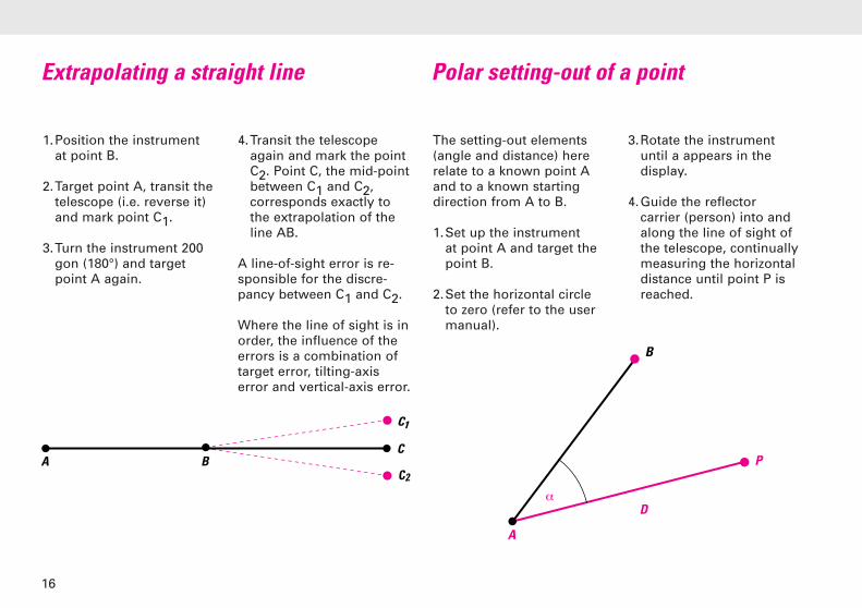
Extrapolating a straight line
1.Position the instrumentat point B.
2.Target point A, transit thetelescope (i.e. reverse it)and mark point C1.
3.Turn the instrument 200gon (180°) and targetpoint A again.
4.Transit the telescopeagain and mark the pointC2. Point C, the mid-pointbetween C1 and C2,corresponds exactly tothe extrapolation of theline AB.
A line-of-sight error is re-sponsible for the discre-pancy between C1 and C2.
Where the line of sight is inorder, the influence of theerrors is a combination oftarget error, tilting-axiserror and vertical-axis error.
The setting-out elements(angle and distance) hererelate to a known point Aand to a known startingdirection from A to B.
1.Set up the instrument at point A and target thepoint B.
2.Set the horizontal circleto zero (refer to the usermanual).
3.Rotate the instrumentuntil a appears in thedisplay.
4.Guide the reflectorcarrier (person) into andalong the line of sight ofthe telescope, continuallymeasuring the horizontaldistance until point P isreached.
A B
C1
C2
C
B
P
D
A
α
Polar setting-out of a point
16

A
BC
Measuring with a total stationPlumbing down from a height point
Plumbing down from aheight point, plumbing upfrom a ground point, andinspecting a vertical line ona structure, can be carriedout exactly in just one tele-scope face, but only if thetelescope describes a pre-cisely-vertical plane whenit is tilted. To ascertain that this is so, proceed asfollows:
1.Target a high point A,then tilt the telescopedownwards and mark theground point B.
2.Transit the telescope, and repeat the procedurein the second face. Markthe point C.
The mid-point between thepoints B and C is the exactplumbing point.
The reason why these twopoints do not coincide canbe a tilting-axis errorand/or an inclined verticalaxis.
For work of this type, makesure that the total stationhas been levelled up pre-cisely, so that the influenceof vertical-axis tilt on steepsights is minimized.
17

Surveys (polar method)
To create e.g. a locationplan, the position andheight of a point on theobject are determined bymeasuring angles anddistances. To do this, theinstrument is set up on any prominent point in alocal coordinate system. A second prominent pointis selected for the purposesof orientation; after thishas been targeted thehorizontal circle is set tozero (refer to the usermanual).
If a coordinate systemalready exists, set up theinstrument on a knownpoint within it and line upthe horizontal circle with a second known point(refer to the user manual).
18

Measuring with the total stationMeasuring distances without a reflector
Each of the TCR totalstations from LeicaGeosystems includes notonly a conventional infra-red distancer that measu-res to prisms, but also anintegrated laser distancerthat requires no reflector.You can switch betweenthese two distancers.
This arrangement bringsmany advantages wherepoints are accessible onlywith difficulty or not at all,for example during therecording of frontages, inpositioning pipes and for measurements acrossgorges or fences.
The visible red laser dot isalso suitable for markingtargets in connection withthe recording of tunnelprofiles or with indoorwork.
The "DISTO" hand-heldlaser meter from LeicaGeosystems is anothersimple instrument thatuses a visible laser beamand needs no reflector; it isparticularly suitable forindoor measurements toascertain spacings, areasand volumes.
Automatic target recognition
The TCA total stations fromLeica Geosystems areequipped with an automatictarget-recognition system("ATR"). This makes tar-geting faster and easier. It isenough to point the tele-scope approximately at thereflector; a touch on abutton then automaticallytriggers the fine pointingand the angle- and distancemeasurements, and recordsall of the values. Thistechnology also makes itpossible to carry out fully-automatic measurementswith the help of a computer.
The ATR can also beswitched to a mode inwhich moving targets canbe followed and measured;
after establishing the initialcontact with the target theinstrument locks on to itand tracks it. The practicalapplications of this optioninclude the preciseguidance of constructionmachinery.
Advantages of ATR: Highspeed of measurement,combined with a constantmeasuring accuracy that is independent of theobserver.
19

Setting out profile boards
During building alignment,it is useful to extrapolatethe sides of the building tobeyond the limits of the ex-cavation and there to erectprofile boards on which theextensions are markedexactly by hammering innails. These can be connec-ted to strings or wires atany time during the con-struction sequence, indi-cating the requiredpositions of the walls.
In the following example,profile boards are to beerected parallel to the pro-posed walls of a largebuilding and at distances ofa and b respectively fromthe boundaries (illustration,left).
1.Establish a baseline ABparallel to the left-handboundary and at a freely-selectable distance c.
2.Mark the point A at thedefined distance d fromthe upper boundary; itwill be the first locationfor the total station.
3.Using a boning rod, markthe point B at the end ofthe baseline.
4.Set up the total station onpoint A, target point B,and set out the points A1,A2 and A3 in this align-ment in accordance withthe planned length of theside of the building.
5.With point B sighted, setthe horizontal circle tozero, turn the total stationby 100 gon (90°) and setout the second line ACwith the points A4, A5and A6.
6.The points on the profileboards are then set outin a similar manner,starting from the pointsA1 to A6 respectively.
If the foundations have notyet been excavated, youcan set out the sides H1H2and H1H3 of the buildingdirectly and use them asthe starting line formarking the points on theprofile boards.
For smaller buildings it iseasier to set out the profileboards using an opticalsquare (right-angle prism)and a measuring tape.
A building-alignmentsoftware programincorporated into manyLeica total stations enablesprofile boards to be set outdirectly, starting with anyinstrument station.
20

Measuring with the total station
a
b
dA
B
A1
c
A2
A3
A4
H1 H3
H2
A5 A6
21

1.549 1.404
A B∆H
d d30m
A B∆H
Soll 1.351Ist 1.496
Inspecting the line of sight (two-peg test)
In new levels, the com-pensator has been adjustedat room temperature, sothat the line of sight is hori-zontal even if the instru-ment is tilted slightly. Thissituation changes if thetemperature fluctuates bymore than ten or fifteendegrees, after a long jour-ney, or if the instrument issubjected to strong vibra-tion. It is then advisable toinspect the line of sight,particularly if more thanone target distance isbeing used.
1. In flat terrain, set up twostaffs not more than 30metres apart.
2.Set up the instrument so that it is equidistantfrom the two staffs (it is enough to pace out thedistance)
3.Read off from both staffsand calculate the heightdifference (illustrationabove).Staff reading A = 1.549Staff reading B = 1.404∆H = A – B = 0.145
4.Set up the instrumentabout one metre in frontof staff A and take thestaff reading (illustrationbelow).Staff reading A = 1.496
5.Calculate the requiredreading B:Staff reading A = 1.496- ∆H = 0.145Required reading
B = 1.351
6.Take the staff reading B. If it differs from therequired reading by morethan 3mm, adjust the lineof sight (refer toinstruction manual).
22
Actual Required 1.351

Instrument errorsInspecting the EDM of the total station
Permanently mark fourruns within the rangetypical for the user (e.g.between 20 m and 200 m).
Using a new distancer, orone that has been cali-brated on a standardbaseline, measure thesedistances three times. The mean values, correctedfor atmospheric influences(refer to the user manual)can be regarded as beingthe required values.
Using these four runs, mea-sure with each distancer at least four times per year.Provided that there are nosystematic errors in excessof the expected measuringuncertainty, the distancer isin order.
23

Instrument errors in the total station
Ideally, the total stationshould meet the followingrequirements:
a) Line of sight ZZ perpen-dicular to tilting axis KK
b) Tilting axis KK perpen-dicular to vertical axis VV
c) Vertical axis VV strictlyvertical
d) Vertical-circle readingprecisely zero at the zenith
If these conditions are notmet, the following terms areused to describe theparticular errors:
a) Line-of-sight error, or colli-mation error c (deviationfrom the right angle bet-ween the line of sight andthe tilting axis)
b) Tilting-axis error a (devia-tion from the right anglebetween the tilting axisand the vertical axis)
c) Vertical-axis tilt (angle
between plumb line andvertical axis).
The effects of these threeerrors on the measurementof horizontal angles increasewith the height differencebetween the target points.
Taking measurements in bothtelescope faces eliminatesline-of-sight errors andtilting-axis errors. The line-of-sight error (and, for highly-precise total stations, alsothe tilting-axis error, which isgenerally very small) canalso be determined andstored. These errors are thentaken into considerationautomatically whenever anangle is measured, and thenit is possible to take mea-surements practically free oferror even using just onetelescope face. The deter-mination of these errors, andtheir storage, are describedin detail in the appropriate
user manual. Vertical-axis tiltdoes not rate as being aninstrument error; it arisesbecause the instrument hasnot been adequately levelledup, and measuring in bothtelescope faces cannoteliminate it. Its influence onthe measurement of thehorizontal and vertical anglesis automatically corrected bymeans of a two-axiscompensator.
d) Height-index error i (theangle between the zenithdirection and the zeroreading of the verticalcircle, i.e. the vertical-circle reading when usinga horizontal line of sight),is not 100 gon (90°), but100 gon + i.
By measuring in both facesand then averaging, theindex error is eliminated; itcan also be determined andstored.
Note:The instrument errorschange with temperature,as a result of vibration, andafter long periods oftransport. If you want tomeasure in just one face,then immediately beforethe measurements youmust determine theinstrument errors and storethem.
V
V
K
K
Z
Z
24

Instrument errors
ci a
25
Vertical-axis tilt Line-of-sight error (c)(Hz collimation)
Height-index error (i)(V index)
Tilting-axis error (a)

Aligning from the mid-point
If intermediate points areto be aligned within a lineof measurement and eachof the two end pointscannot be seen from theother, proceed as follows:
1.Select two points 1 and 2(both approximately inthe alignment) fromwhich both end points Aand E are visible. Usesight poles to mark thepoints.
2.From point 1, align point2 in the straight line 1 – A
3.From point 2, align point3 in the straight line 2 – E
4.From point 3, align point4 in the straight line 3 – Aand continue in the samemanner until no furtherlateral deviations arevisible at the two inter-mediate points.
A
E1
32
4
26

Simple surveying tasksMeasuring slopes
If slopes are to be deter-mined in % or to be stakedout, e.g. for gutters,pipelines or foundations,two different methods areavailable.
1. With a levelMeasure the heightdifference and thedistance (either opticallywith the stadia hairs orwith the tape). The slopeis calculated as follows:100 ∆H / D = slope in %
2. With a theodolite ortotal stationPlace the instrument ona point along thestraight line the slope ofwhich is to be deter-mined, and position astaff at a second pointalong that line.
Using the telescope,determine the instrumentheight i at the staff.The vertical-circle readinggiving the zenith angle in gon or degrees can bereset to % (refer to usermanual) so that the slopecan be read off directly in %. The distance isirrelevant.
A reflector pole fitted witha prism can be usedinstead of the staff. Extendthe reflector pole to theinstrument height i and usethe telescope to target thecentre of the prism.
∆H
D
ii
V%
27

Measuring right-angles
The most accurate way toset out a right-angle is touse a theodolite or a totalstation. Position theinstrument on the pointalong the survey line fromwhich the right-angle is tobe set out, target the endpoint of the survey line, setthe horizontal circle to zero(see user manual) and turnthe total station until thehorizontal circle reading is100 gon (90°).
For setting out a right-angle where the accuracyrequirements are lessdemanding, e.g. for smallbuildings or whendetermining longitudinaland transverse profiles, thehorizontal circle of a levelcan be used. Set up thelevel over the appropriatepoint of the survey linewith the help of a plumbbob suspended from the
central fixing screw of thetripod. Then turn thehorizontal circle by hand tozero in the direction of thesurvey line or of thelongitudinal profile. Finally,turn the level until theindex of the circle is set to100 gon (90°).
An optical square is thebest solution for theorthogonal surveying of apoint on a survey line orvice versa, and for thesetting out at right-anglesof a point in the neardistance. The beam of lightfrom the object point isturned through 90° by apentagonal prism so that itreaches the observer. Theoptical square consists oftwo superimposedpentagonal prisms withtheir fields of view facingright and left respectively.Between the two prisms is
an unrestricted view of theobject point. You as theobserver can positionyourself in the survey line(defined by two vertically-positioned alignment rods)in that you move perpen-dicularly to the line untilyou see the images of thetwo rods exactly super-imposed. Then you moveyourself along the surveyline until the object pointand the two images of thealignment rods all coincide.
28

Applications programsCalculating areas
A
B
C
D
1. Set up the total stationin the terrain so that it iswithin view of the entirearea to be surveyed. It isnot necessary to positionthe horizontal circle.
2. Determine the boundarypoints of the areasequentially in theclockwise direction. Youmust always measure adistance.
3. Afterwards, the area iscalculated automaticallyat the touch of a buttonand is displayed.
29

P'
∆DP
N
α
1. Set up the instrument ata known point andposition the horizontalcircle (refer to the sec-tion "Setting the station”in the user manual).
2.Enter manually the coor-dinates of the point to bestaked out. The programautomatically calculatesdirection and distance(the two parametersneeded for staking out).
3.Turn the total stationuntil the horizontal circlereads zero.
4.Position the reflector atthis point (point P’).
5.Measure the distance;the difference in thedistance ∆D to the pointP will be displayedautomatically.
Alternatively, the coordi-nates of the points to bestaked out can be trans-ferred beforehand, back inthe office, from thecomputer to the totalstation. Under thesecircumstances, in order tostake out, only the pointnumber then needs to beentered.
Staking out
30

Applications programs
1. Set up a reflector verti-cally beneath that pointthe height of which is tobe determined. The totalstation itself can besituated anywhere.
2.Measure the distance tothe reflector.
3.Target the high point.
4.The height difference Hbetween the groundpoint and the high pointis now calculated at thetouch of a button and isdisplayed.
Remote heights
H
31
AH
D B
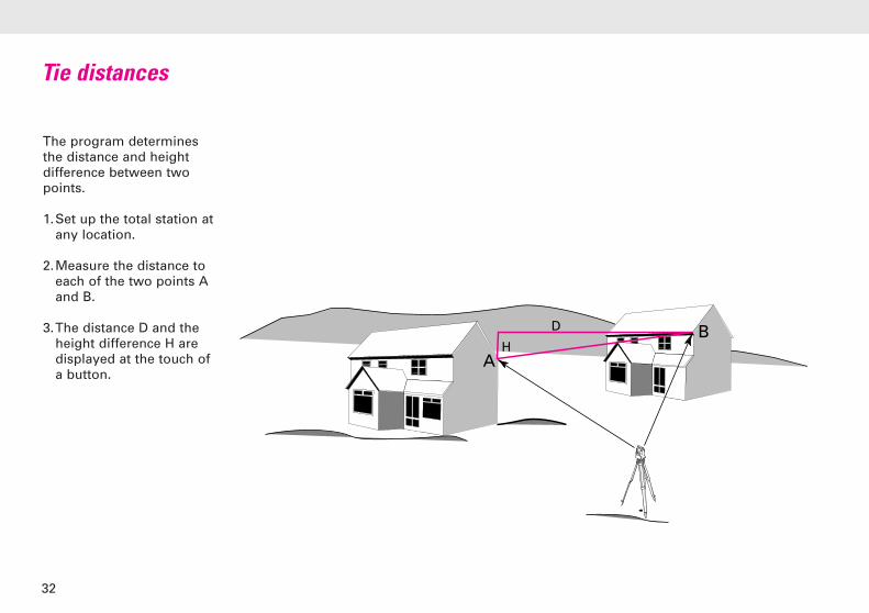
The program determinesthe distance and heightdifference between twopoints.
1.Set up the total station atany location.
2.Measure the distance toeach of the two points Aand B.
3.The distance D and theheight difference H aredisplayed at the touch ofa button.
Tie distances
32

Applications programs
�N (x)
Hz=0
H
E (y)
This program calculatesthe position and height ofthe instrument station,along with the orientationof the horizontal circle,from measurements to atleast two points, thecoordinates of which areknown.
The coordinates of the tiepoints can be enteredmanually or they can bestored in the instrumentbeforehand.
Free stationing has thegreat advantage that, forlarge projects involvingsurveying or staking out,you can choose the mostfavourable station for theinstrument. You are nolonger forced to use aknown point that is in anunsatisfactory location.
Free-station surveys
The options for measuring,and the measuringprocedure, are described indetail in the user manuals.
Note:When performing surveytasks that involvedetermining heights orstaking them out, alwaysremember to take theheight of the instrumentand that of the reflectorinto account.
33

Recording points
Orientation and height transfer
Resection
Tie distance
Staking out
Remote heights
Free-station surveys
Reference line
Hidden points
Area computation
Sets of angles
Traversing
Local resection
COGO (computations)
Automatic storage
Scanning surfaces
Digital terrain models
Offset
The applications programs available
34

Surveying with GPS
GPS surveys use thesignals transmitted bysatellites having trajectoriessuch that any point on theEarth’s surface can bedetermined around theclock and independently ofweather conditions. Thepositioning accuracydepends on the type ofGPS receiver and on theobservation and post-processing techniquesused.
Compared with the use of atotal station, GPS surveyingoffers the advantage thatthe points to be measureddo not have to be mutuallyvisible. Today, providedthat the sky is relativelyunobstructed (by trees,buildings etc.) and there-fore that adequate satellitesignals can be received,GPS equipment can beapplied to many survey
Surveying with GPS
35
tasks that until recentlywere carried out usingelectronic total stations.
The new GPS System 500from Leica Geosystemsenables the most diverserange of survey tasks to becarried out with centimetreaccuracy – on the tripod;on the plumbing pole; onships, vehicles andconstruction plant; andusing both static andkinematic applications.

Leica Geosystems AG
CH-9435 Heerbrugg
(Switzerland)
Phone +41 71 727 31 31
Fax +41 71 727 46 73
www.leica-geosystems.com
Illustrations, descriptions and technical data are not binding and may be changed. Printed in Switzerland.
Copyright Leica Geosystems AG, Heerbrugg, Switzerland, 2000722510en – VII.00 – RVA