29 june 2004paul dauncey1 ecal readout tests paul dauncey for the calice-uk electronics group a....
Post on 19-Dec-2015
216 views
TRANSCRIPT

29 June 2004 Paul Dauncey 1
ECAL Readout Tests
Paul Dauncey
For the CALICE-UK electronics groupA. Baird, D. Bowerman, P. Dauncey, C. Fry, R. Halsall, M. Postranecky, M.Warren, O. Zorba
Thanks to: J.C. Vanel, J. Fleury, C. de la Taille
29 June 2004 Paul Dauncey 2
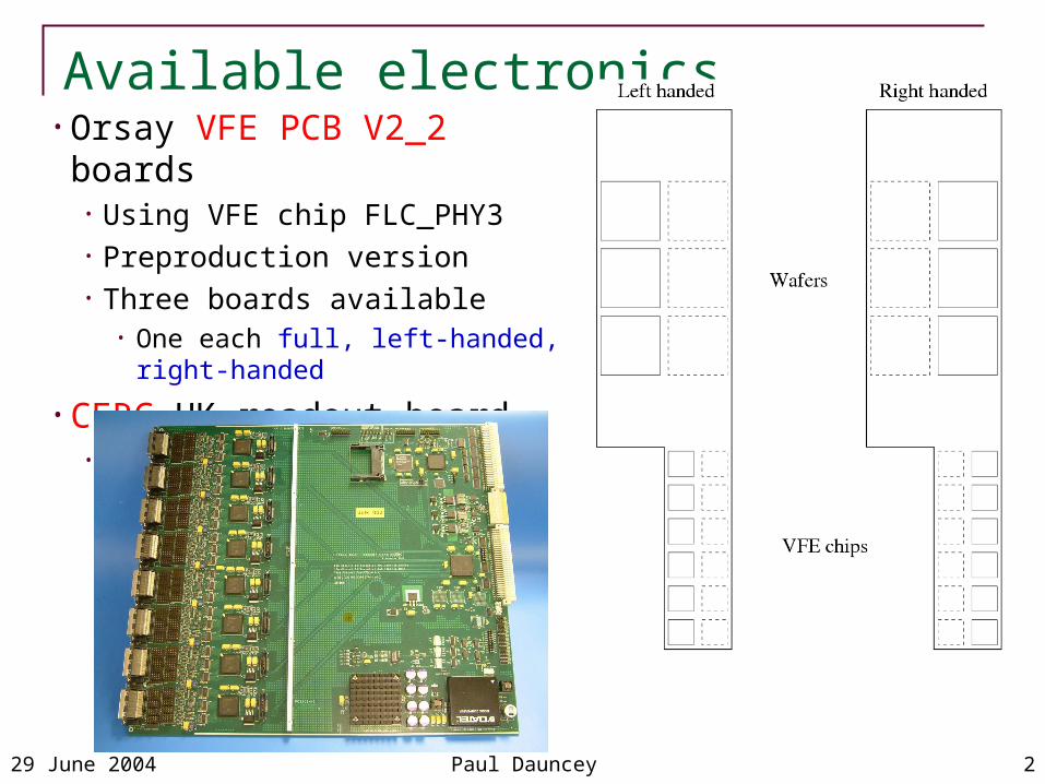
Available electronics• Orsay VFE PCB V2_2 boards
• Using VFE chip FLC_PHY3• Preproduction version• Three boards available
• One each full, left-handed, right-handed
• CERC UK readout board• Prototype version

29 June 2004 Paul Dauncey 3
Test motivation• Tests which were done
• Noise measurements• Calibration with DAC• Cosmics in LLR teststand
• To check• Problems: are there things which don’t work?• Uniformity: do all channels look similar?• Stability: is the system stable with time?• Dynamic range and signal/noise: are they sufficient?• Optimisation: are there changes which will improve the system?
• Aim to verify VFE PCB V2_2 and so release for production• More details of test results available from
http://www.hep.ph.imperial.ac.uk/calice/elecPrototypeTests/electronics.html

29 June 2004 Paul Dauncey 4
Wafer 1
Noise tests• Software selectable gain on VFE PCBs; x1 or x10• Full PCB has 6 wafers mounted; wafer 1 does not deplete
Gain x10Gain x1
Gain x1 noise= 7.2 ADC counts, gain x10 noise= 52 ADC counts
1 ADC count = 78V. No obvious dead channels
Wafer 1
Known problem on CERC
29 June 2004 Paul Dauncey 5
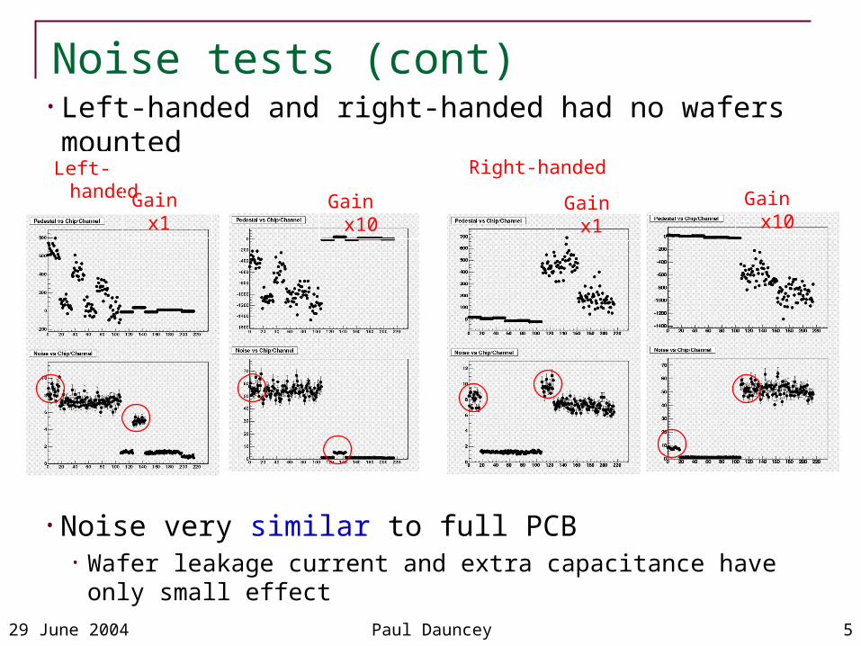
Noise tests (cont)• Left-handed and right-handed had no wafers mounted
Left-handed Right-handed
Gain x1 Gain x10Gain x1Gain x10
• Noise very similar to full PCB• Wafer leakage current and extra capacitance have only small effect

29 June 2004 Paul Dauncey 6
Calibration with DAC• Need to determining timing
• Output signal is shaped by CR-RC circuit, shaping time ~200ns• Adjust HOLD start time so that sample-and-hold captures peak• Can change HOLD time in software configuration; steps of 6.25ns• Scan HOLD time and fit for peak
• With HOLD timing set correctly, scan DAC• From zero to channel saturation• 16-bit DAC, 1 DAC count = 20 V• Determine mean and noise at each point• Fit for intercept and response
• Channels divided into 6 groups for DAC• Calibration can be enabled independently for each group• Look at response of non-enabled channels• Measure crosstalk

29 June 2004 Paul Dauncey 7
HOLD timing determination• Typical channel (first one on right-handed PCB), gain x1• Fit CR-RC xe1–x shape to response (averaged over 19 events)• Shaping time = p3 = 31.36 units = 196 ns
29 June 2004 Paul Dauncey 8
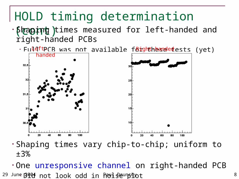
HOLD timing determination (cont)• Shaping times measured for left-handed and right-handed PCBs
• Full PCB was not available for these tests (yet)Left-handed Right-handed
• Shaping times vary chip-to-chip; uniform to ±3%• One unresponsive channel on right-handed PCB
• Did not look odd in noise plot

29 June 2004 Paul Dauncey 9
DAC scan
• Slope = 2.484 ADC counts/DAC count = 9.57V/V• High end saturation at ~ 12000 DAC counts ~244 mV
• Does not make good use of full DAC range• 16-bits is 0-65535 counts = 0-1.33V; five times higher
• Low end saturation from CERC board; understood
• Typical channel (same as for DAC scan), gain x1

29 June 2004 Paul Dauncey 10
DAC scan (cont)• Results for left-handed and right-handed PCBs
Left-handed Right-handed
• Responses uniform to ±10%• Same unresponsive channel on right-handed PCB shows up here

29 June 2004 Paul Dauncey 11
DAC scan (cont)• Typical channel; noise vs DAC setting
• Extra noise ~ 0.025 ADC counts/DAC count ~ 10mV/V• Equivalent to extra noise of 1% of signal size• Unknown if from calibration circuit or present in real signals• Clips off at saturation; other noise does not (understood?)
29 June 2004 Paul Dauncey 12
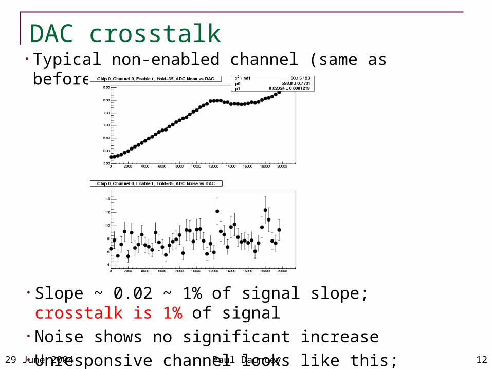
DAC crosstalk• Typical non-enabled channel (same as before)
• Slope ~ 0.02 ~ 1% of signal slope; crosstalk is 1% of signal• Noise shows no significant increase• Unresponsive channel looks like this; calibration not connected?
29 June 2004 Paul Dauncey 13
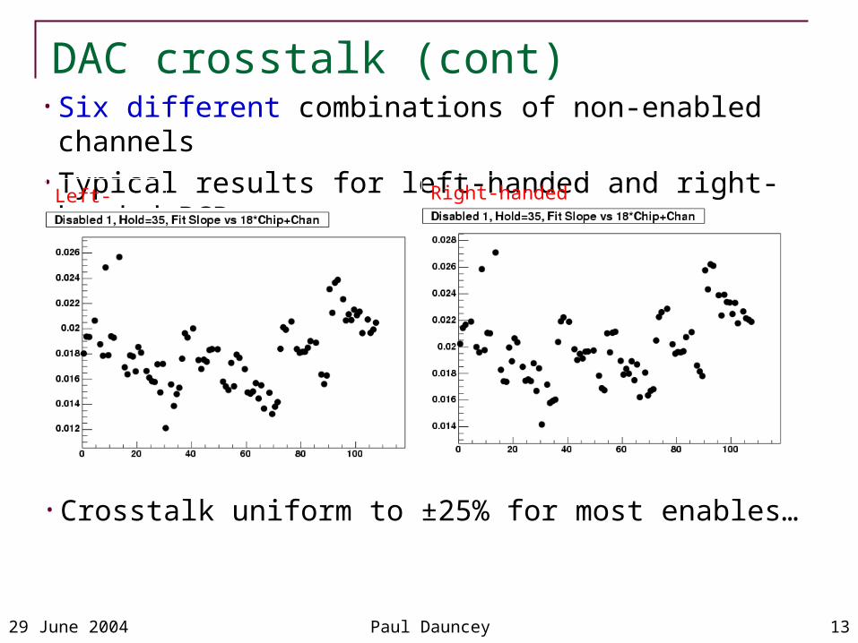
DAC crosstalk (cont)
• Crosstalk uniform to ±25% for most enables…
• Six different combinations of non-enabled channels• Typical results for left-handed and right-handed PCBs
Left-handed Right-handed

29 June 2004 Paul Dauncey 14
DAC crosstalk (cont)
• Systematic on both PCBs• Highest are channel 17, lowest are channel 12
• Look at response in more detail
• …but enables 2 and 5 show odd response
Left-handed Right-handed

29 June 2004 Paul Dauncey 15
DAC crosstalk (cont)
• Channel 17• Slope ~ 1 ADC
counts/DAC count ~ 40% crosstalk
• Typical channels for the highest and lowest points
• Channel 12• Slope ~ –0.3 ADC
counts/DAC count ~ –10% crosstalk
• Unknown if from calibration circuit or present in real signals

29 June 2004 Paul Dauncey 16
ADC and DAC range optimisation• Pedestals within ~1000 ADC counts of zero; required for SSD• 16-bit ADC range is –32768 - 32767; only uses upper 15 bits• One PCB resistor change (in parallel) can shift pedestal negative• Quick check with 4.7k resistor on left-handed PCB
• Pedestal shifted to ~ –13000; gain and noise unchanged• Output range would be ~ –13000 - 18000; better centred
• Can then adjust gain of production CERCs to use most of 16 bit range

29 June 2004 Paul Dauncey 17
ADC and DAC range optimisation (cont)• DAC range underused by factor of ~ 5; only uses lower 14 bits• One PCB resistor change (in series) to rescale DAC gain• Quick check with 50 resistor on left-handed PCB
• Slope = 0.499 ADC counts/DAC count = 1.92V/V• High end saturation at ~ 60000 DAC counts ~ 1.2V
• Much better match to DAC range
• Noise smaller even allowing for factor of five• Implies not DAC related, but due to PCB

29 June 2004 Paul Dauncey 18
Cosmics run• Full PCB used in Ecole Polytechnique teststand, but…
• Wafer 1 not depleted• Bad ADC on CERC for wafer 4; half the wafer has very high noise
• Ran over weekend 18-21 June• Total ~ 57 hours, 130083 events• Around 90% have unique track from scintillators• Interpolate into plane of PCB; check for ADC value > 40 above pedestal

29 June 2004 Paul Dauncey 19
Cosmics alignment• Compare x and y scintillator interpolation with channel position
• Single peaks; proves no mis-wiring of channels or readout• Hence, align coordinate systems to agree
• Width of x and y distributions ~ 0.9cm
x y
x y

29 June 2004 Paul Dauncey 20
Cosmic signal response
• Simple Gaussian fit gives signal peak at 45 ADC counts = 3.5mV• But S/N = 4.3, i.e. noise is 10.5 counts, not 7 counts
• Require interpolation within 0.9cm of pad centre• All (good) channels combined

29 June 2004 Paul Dauncey 21
Cosmic signal response (cont)
• Clear signal seen in all good chips
• Divide into separate chips• Wafer 1 is chips 2 and 3, bad ADC is chip 8
Chips 0-3
Chips 4-7
Chips 8-11

29 June 2004 Paul Dauncey 22
Cosmic signal response (cont)• Look at signal and S/N for good chips
• Both uniform to ± 3%• Fit gives higher signal ~ 49, and hence S/N ~ 4.9

29 June 2004 Paul Dauncey 23
Cosmic signal response (cont)• Pushing the stats, look at signal and S/N for good channels
• No obvious bad channels…

29 June 2004 Paul Dauncey 24
Stability over cosmics run• Continuous data for 2.5 days; check pedestals vs time• Drifts of up to 15 counts (2) seen• Same trend in all channels
• Very similar within a chip, less so chip-to-chip
• Temperature? Not measured during run• Need to monitor temperature in future to check this
• Need temperature sensors mounted on PCBs and/or wafers?
Chip 0 Chip 3
29 June 2004 Paul Dauncey 25
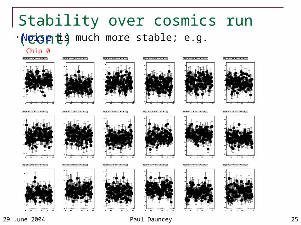
Stability over cosmics run (cont)• Noise is much more stable; e.g.
Chip 0

29 June 2004 Paul Dauncey 26
Conclusions• Basic conclusion is that the system works!
• We have all parts of the VFE PCB functioning
• Some oddities seen in calibration• Noise depends on DAC, some channels have high crosstalk• Must determine if due to calibration or if will occur in real data; how?
• Adjustment of the VFE PCB would optimise match to CERC• Working point for ADC and gain for DAC
• CERC has some bugs• Fixes are in hand and will be implemented for the production version
• Signal seen around 50 counts, noise around 7 counts• But realistic signal/noise in cosmics around 5
• Significant pedestal drifts observed• Will need frequent pedestal measurements during run; between spills?• Will need temperature monitoring?