2.72 elements of mechanical design - mit opencourseware
TRANSCRIPT
MIT OpenCourseWare http://ocw.mit.edu
2.72 Elements of Mechanical Design Spring 2009
For information about citing these materials or our Terms of Use, visit: http://ocw.mit.edu/terms.

2.72Elements of
Mechanical Design
Lecture 12:Belt, friction, gear drives

Schedule and reading assignment Quiz
� Bolted joint qualifying Thursday March 19th
Topics � Belts
� Friction drives
� Gear kinematics
Reading assignment • Read:
14.1 – 14.7
• Skim: Rest of Ch. 14
© Martin Culpepper, All rights reserved 2

3© Martin Culpepper, All rights reserved
Topic 1:
Belt Drives
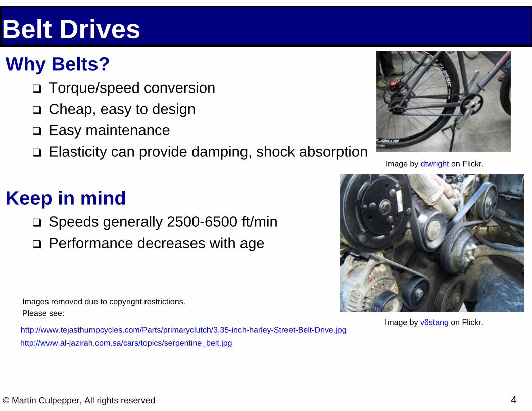
Belt Drives Why Belts?
� Torque/speed conversion
� Cheap, easy to design
� Easy maintenance
� Elasticity can provide damping, shock absorptionImage by dtwright on Flickr.
Keep in mind � Speeds generally 2500-6500 ft/min
� Performance decreases with age
Image by v6stang on Flickr.
© Martin Culpepper, All rights reserved 4
Images removed due to copyright restrictions.Please see:
http://www.tejasthumpcycles.com/Parts/primaryclutch/3.35-inch-harley-Street-Belt-Drive.jpghttp://www.al-jazirah.com.sa/cars/topics/serpentine_belt.jpg

Belt Construction and Profiles Many flavors
� Flat is cheapest, natural clutch � Vee allows higher torques � Synchronous for timing
Usually composite structure � Rubber/synthetic surface for friction � Steel cords for tensile strength
© Martin Culpepper, All rights reserved 5
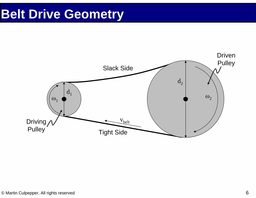
Belt Drive Geometry
Driven
Slack Side
Tight Side
Driving Pulley
Pulley
ω1 ω2
d1
d2
vbelt
© Martin Culpepper, All rights reserved 6

Belt Drive Geometry
θ1
θ2
dspan
dcenter
© Martin Culpepper, All rights reserved 7

Contact Angle Geometry
θ1
θ2
dspan
dcenter
ω1 ω2 d1
d2
θ1 =π −2sin−1 ⎜⎜⎛ d2 −d1
⎟⎟⎞
θ2 =π +2sin−1 ⎜⎜⎛ d2 −d1
⎟⎟⎞
⎝ 2dcenter⎠ ⎝ 2dcenter⎠ © Martin Culpepper, All rights reserved 8
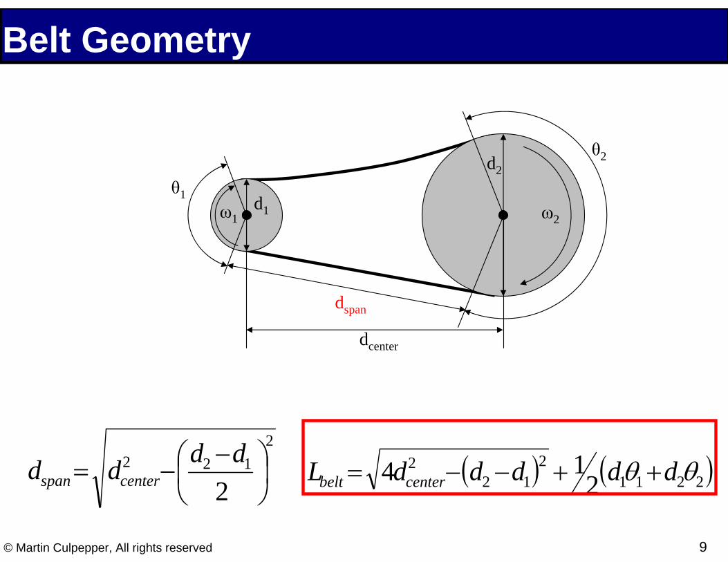
Belt Geometry
θ1
θ2
dspan
dcenter
ω1 ω2 d1
d2
2 2 1d = 2 2 12(d1θ1 +d2θ2 )4dcenter−(d2 −d1) +span dcenter−⎜
⎛ d −d ⎟⎞
2
Lbelt = ⎝ 2 ⎠
© Martin Culpepper, All rights reserved 9
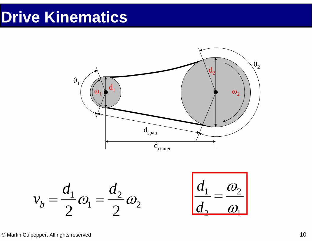
Drive Kinematics
θ1
θ2
dspan
dcenter
ω1 ω2 d1
d2
vb = d 2
1 ω1 = d 2
2 ω2
d1 =ω2
d2 ω1
© Martin Culpepper, All rights reserved 10

Elastomechanics Elastomechanics → torque transmission
� Kinematics → speed transmission
Link belt preload to torque transmission � Proceeding analysis is for flat/round belt
Driven
Slack Side
Tight Side
Driving Pulley
Pulley
ω1 ω2
d1
d2
vbelt
© Martin Culpepper, All rights reserved 11

Free Body Diagram
y
xdS
F
F+dF
dθ
dN
μdN
d/2
•Tensile force (F)
•Normal force (N)
•Friction force (μN)
•Centrifugal force (S)
© Martin Culpepper, All rights reserved 12
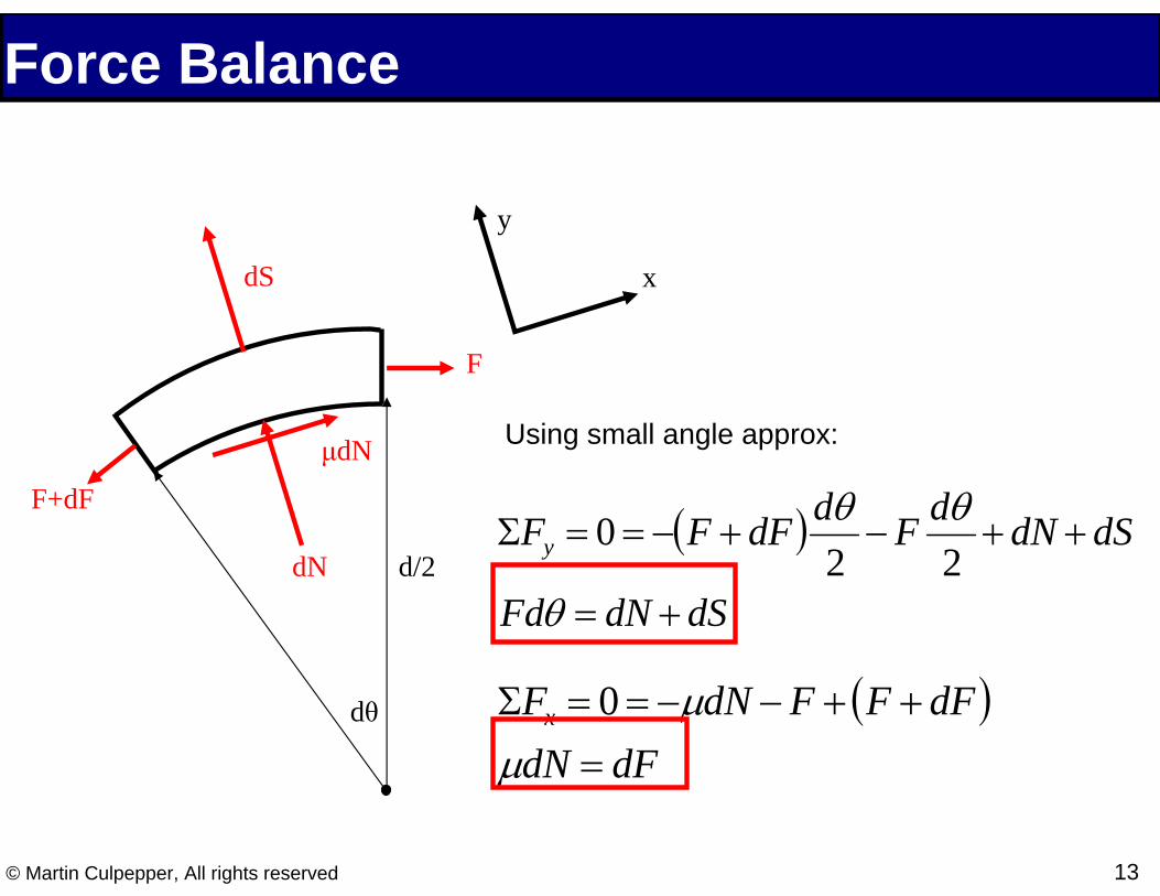
Force Balance
d/2
dθ
dN
μdN
F
Using small angle approx:
F+dF ΣFy = 0 = −(F + dF) dθ − F dθ
+ dN + dS 2 2
Fdθ = dN + dS
ΣFx = 0 = −μdN − F + (F + dF) μdN = dF
y
dS x
© Martin Culpepper, All rights reserved 13

Obtaining Differential Eq
d/2
dθ
dN
μdN
F
Let m be belt mass/unit length
F+dF dS = m⎜⎛ d ⎟⎞
2
ω2dθ ⎝ 2⎠
Combining these red eqns:
dF = μFdθ − μm ⎛⎜ d ⎞⎟
2
ω 2dθ ⎝ 2 ⎠
y
dS x
dF − μF = −μm ⎛⎜
d ⎞⎟
2
ω 2
dθ ⎝ 2 ⎠
© Martin Culpepper, All rights reserved 14

Belt Tension to Torque Let the difference in tension between the loose side (F2) and the tight side (F1) be related to torque (T)
TF − F =
T
F11 2 d 2
Solve the previous integral over contact angle and apply F1 and F2 as b.c.’s and then do a page of algebra:
contact F2T eμθ + 1 =Ftension d eμθcontact − 1
2 μθcontact
F1 = m ⎛⎜ d ⎞⎟ ω 2 + Ftension
2 μθ
econtact⎝ 2 ⎠ e + 1 Used to find stresses
in belt!!! ⎛ d ⎞
22 2F2 = m⎜ ⎟ ω + Ftension
⎝ 2 ⎠ eμθcontact + 1 © Martin Culpepper, All rights reserved 15

Practical Design Issues Pulley/Sheave profile
� Which is right?
Manufacturer → lifetime eqs � Belt Creep (loss of load capacity) � Lifetime in cycles
Idler Pulley Design � Catenary eqs → deflection to tension � Large systems need more than 1
A B C
Images by v6stang on Flickr.
© Martin Culpepper, All rights reserved 16
IDL
Idler
ALT
Waterpump& fan
Crank
P/S
Idler
Figure by MIT OpenCourseWare.
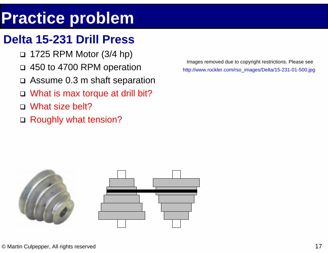
Practice problem Delta 15-231 Drill Press
�
�
�
�
�
�
1725 RPM Motor (3/4 hp)450 to 4700 RPM operation
Assume 0.3 m shaft separation
What is max torque at drill bit?
What size belt?
Roughly what tension?
Images removed due to copyright restrictions. Please see http://www.rockler.com/rso_images/Delta/15-231-01-500.jpg
© Martin Culpepper, All rights reserved 17
18© Martin Culpepper, All rights reserved
Topic 2:
Friction Drives

Friction Drives Why Friction Drives?
� Linear ↔ Rotary Motion � Low backlash/deadband � Can be nm-resolution
Keep in mind � Preload → bearing selection � Low stiffness and damping � Needs to be clean � Low drive force
Images removed due to copyright restrictions. Please see
http://www.beachrobot.com/images/bata-football.jpg
© Martin Culpepper, All rights reserved 19
http://www.borbollametrology.com/PRODUCTOS1/Wenzel/WENZELHorizontal-ArmCMMRSPlus-RSDPlus_files/rsplus.jpg
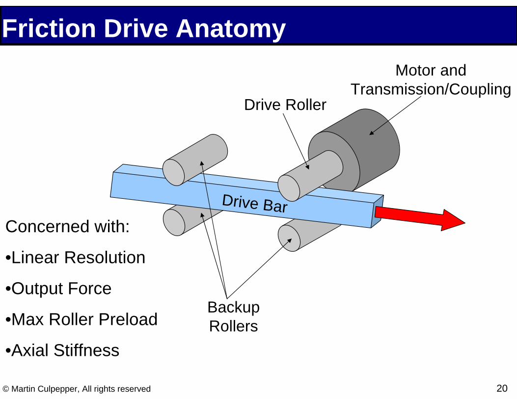
Friction Drive Anatomy
Transmission/Coupling
Drive Bar
Motor and
Drive Roller
Concerned with:
•Linear Resolution
•Output Force Backup
•Max Roller Preload Rollers •Axial Stiffness
© Martin Culpepper, All rights reserved 20
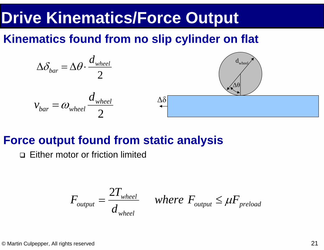
Drive Kinematics/Force Output Kinematics found from no slip cylinder on flat
Δδbar = Δθ ⋅ dwheel
2
v =ω dwheel Δδ
dwheel
Δθ
bar wheel 2
Force output found from static analysis � Either motor or friction limited
Foutput = 2Twheel where Foutput ≤ μFpreloaddwheel
© Martin Culpepper, All rights reserved 21

Maximum Preload 1
1
2
1 −
⎟⎟ ⎟
⎠
⎞
⎜⎜ ⎜
⎝
⎛ +=
crownwheel e rdR
3 1
2 3
⎟⎟ ⎠
⎞ ⎜⎜ ⎝
⎛ =
e
epreload contact E
RF a
122 11 −
⎟⎟ ⎠
⎞ ⎜⎜ ⎝
⎛ −+
− =
bar
bar
wheel
wheel e EE
E νν
( ) ( )⎟ ⎠ ⎞
⎜ ⎝ ⎛ +⋅+⋅++
= wheelwheel wheel
e
econtact wheel R
Ea ννν π
τ 121 9 2
2 21
2
2 3
max yσ
τ =
For metals:
Variable Definitions
Shear Stress Equation
16π 3τ 3 R2max eFpreload , max = 3
3Ee 2 ⎛⎜
1+ 2ν wheel + 2 ⋅ (1+ν wheel )⋅ 2(1+ν wheel )⎟⎞
⎝ 2 9 ⎠
© Martin Culpepper, All rights reserved 22

Axial Stiffness −1
⎛ ⎞⎜ ⎟ 4aeEe⎜ 1 1 1 1 ⎟ ktangential = kaxial = ⎜ k
+ ktorsion +
k +
k ⎟ (2 −ν )( 1+ν ) ⎜ shaft
2 tangential bar ⎟
⎝ dwheel ⎠ 43πEd shaftk shaft = 4 L3
4πGd wheelk torsion = 32 L
k = EA c , bar
bar L
© Martin Culpepper, All rights reserved 23

Friction Drives Proper Design leads to
� Pure radial bearing loads
� Axial drive bar motion only
Drive performance linked to motor/transmission � Torque ripple
� Angular resolution
Images removed due to copyright restrictions. Please see
http://www.borbollametrology.com/PRODUCTOS1/Wenzel/WENZELHorizontal-ArmCMMRSPlus-RSDPlus_files/rsplus.jpg
© Martin Culpepper, All rights reserved 24

25© Martin Culpepper, All rights reserved
Topic 3:
Gear Kinematics

Gear Drives Why Gears?
� Torque/speed conversion � Can transfer large torques � Can run at low speeds � Large reductions in small package
Keep in mind � Requires careful design � Attention to tooth loads, profile
Image from robbie1 on Flickr.
Image from jbardinphoto on Flickr.
Images removed due to copyright restrictions. Please see http://elecon.nlihost.com/img/gear-train-backlash-and-contact-pattern-checking.jpg
http://www.cydgears.com.cn/products/Planetarygeartrain/planetarygeartrain.jpg
© Martin Culpepper, All rights reserved 26

Gear Types and Purposes Spur Gears
� Parallel shafts � Simple shape → easy design, low $$$ � Tooth shape errors → noise � No thrust loads from tooth engagement
Helical Gears � Gradual tooth engagement → low noise � Shafts may or may not be parallel � Thrust loads from teeth reaction forces � Tooth-tooth contact pushes gears apart
Images from Wikimedia Commons, http://commons.wikimedia.org
© Martin Culpepper, All rights reserved 27

Gear Types and Purposes Bevel Gears
� Connect two intersecting shafts� Straight or helical teeth
Worm Gears � Low transmission ratios� Pinion is typically input (Why?)� Teeth sliding → high friction losses
Rack and Pinion � Rotary ↔ Linear motion Images from Wikimedia Commons, http://commons.wikimedia.org
� Helical or straight rack teeth
© Martin Culpepper, All rights reserved 28
k
F (t)
k
Viscous damping, c
Rack, m1
Pinion, m2
+b
a
Figure by MIT OpenCourseWare.
Rack & Pinion
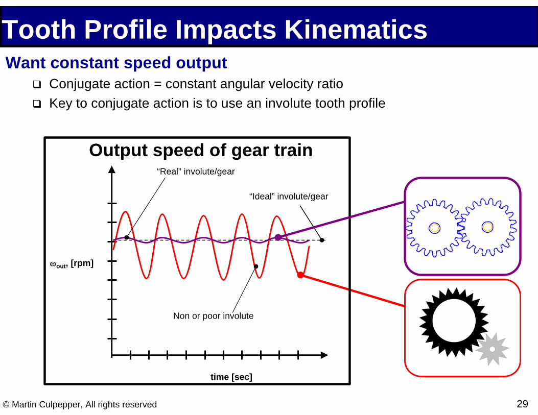
Tooth Profile Impacts Kinematics Want constant speed output
� Conjugate action = constant angular velocity ratio � Key to conjugate action is to use an involute tooth profile
Output speed of gear train
time [sec]
ωout, [rpm]
“Ideal” involute/gear
Non or poor involute
“Real” involute/gear
© Martin Culpepper, All rights reserved 29
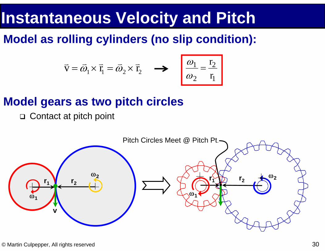
Instantaneous Velocity and Pitch Model as rolling cylinders (no slip condition):
v v =ωv 1 × v r1 =ω
v 2 ×
v r2
ω1 = r2
ω2 r1
Model gears as two pitch circles � Contact at pitch point
r1
ω1
ω2r2r1
ω1
ω2
v
Pitch Circles Meet @ Pitch Pt.
r2
© Martin Culpepper, All rights reserved 30

Instantaneous Velocity and Pitch Meshing gears must have same pitch
-Ng = # of teeth, Dp = Pitch circle diameter
NgDiametral pitch, PD: PD =
Dp
Circular pitch, PC: PC = πDp =
π
Ng PD
© Martin Culpepper, All rights reserved 31

Drawing the Involute Profile
Φ Pitch Point
Base Circle
Pitch Circle
DP/2
DB/2
•Gear is specified by diametral pitch and pressure angle, Φ
Images from Wikimedia Commons, http://commons.wikimedia.org
Image removed due to copyright restrictions. Please see http://upload.wikimedia.org/wikipedia/commons/c/c2/Involute_wheel.gif
© Martin Culpepper, All rights reserved 32
Φ= cosPB DD
33© Martin Culpepper, All rights reserved
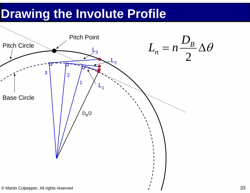
Drawing the Involute Profile
θΔ= 2
B n
D nL
DB/2
1 23
Pitch Point Pitch Circle
Base Circle
L3
L2
L1

Transmission Ratio for Serial Gears
Transmission ratio for elements in series: TR = (proper sign)⋅ ωout
ωin
From pitch equation: P1 = N1 =
N2 = P2 D1 N1 ω2= =
D1 D2 D2 N2 ω1
For Large Serial Drive Trains:
Gear trainPower in: Tin y ωin
Power out: Tout y ωout
11 2
TR = (proper sign)⋅ Productof drivingteeth Productof driven teeth
© Martin Culpepper, All rights reserved 34

Transmission Ratio for Serial Gears Serial trains: TR = ( proper sign)⋅ Product of driving teeth
Product of driven teeth Example 1:
TR = ?
in out
Example 2: driven
drive
driven
drive driven
drive
TR = ?
in out
© Martin Culpepper, All rights reserved 35

Transmission Ratio for Serial Gears Example 3: Integral gears in serial gear trains
� What is TR? Gear 1 = input and 5 = output
TR = (proper sign)⋅ Product of driving teeth Product of driven teeth
Gear - 1N1 = 9
Gear - 2N2 = 38
Gear - 3N3 = 9
Gear - 4N4 = 67
4
1
5
3
2
Gear - 5N5 = 33
© Martin Culpepper, All rights reserved 36

ω2
Planetary Gear Trains Planetary gear trains are very common
� Very small/large TRs in a compact mechanism
Terminology:
Planet Planet Ring Planet gear gear gear Arm
Planet Arm
PlanetSun gear gear
© Martin Culpepper, All rights reserved 37

Planetary Gear Train Animation How do we find the transmission
ratio?
Image removed due to copyright restrictions. Please see http://www.cydgears.com.cn/products/Planetarygeartrain/ planetarygeartrain.jpg
Sun
Ring gear
Planet gear
Arm
Trai
n 1
Sun
Ring gear
Planet gear
Arm
Trai
n 2
© Martin Culpepper, All rights reserved 38

Planetary Gear Train TR
Sun Gear
Planet Gear
Arm
If we make the arm stationary, than this is a serial gear train:Ring Gear
ωra ωring −ωarm= = TRω ω −ωsa sun arm
Nsun N planet NsunTR = − ⋅ = −N planet Nring Nring
ω pa =ω planet −ωarm = TR
ωsa ωsun −ωarm NsunTR = −
N planet
© Martin Culpepper, All rights reserved 39
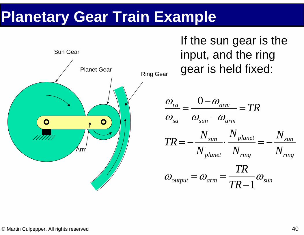
Planetary Gear Train Example If the sun gear is the input, and the ring gear is held fixed:Ring Gear
ω 0 −ωra arm= = TRω ω −ωsa sun arm
Nsun N planet NsunTR = − ⋅ = −N planet Nring Nring
TRω =ω = ωoutput arm sunTR −1
Sun Gear
Planet Gear
Arm
© Martin Culpepper, All rights reserved 40

Case Study: Cordless Screwdriver Given: Shaft TSH (ωSH) find motor TM (ωSH)
� Geometry dominates relative speed (Relationship due to TR)
2 Unknowns: TM and ωM with 2 Equations: � Transmission ratio links input and output speeds � Energy balance links speeds and torques
© Martin Culpepper, All rights reserved 41

Example: DC Motor shaft T(ω): T( ) = TS ⋅
⎛⎜⎜1−
ω ⎞⎟⎟ω Motor torque-speed curve
⎝ ωNL ⎠ T(ω)P(ω) obtained from P(ω) = T(ω) y ω
Speed at maximum power output:
P( ) ( ) ω = T ω ⋅ω = TS ⋅⎜⎛ω −
ω 2 ⎟⎞ ω
⎜ ω ⎟⎝ NL ⎠ P(ω
ωPMAX =ω
2 NL
PMAX
PMAX = TS ⋅⎛⎜ωNL ⎞⎟⎝ 4 ⎠
(ωNL , 0 )
( 0 , TS )
)
ω
Motor power curve
ωPMAX
(ωNL , 0 )
© Martin Culpepper, All rights reserved 42

Example: Screw driver shaft A = Motor shaft torque-speed curve What is the torque-speed curve for the screw driver?
ω
T(ω)
A
B
C
Train ratio = 1/81
SCREW DRIVER SHAFT
Screw Driver Shaft
MOTOR SHAFT TM, ωM
TSH, ωSH
GT-2 Electric Motor GT-1
GEAR train # 1 GEAR train # 2
System boundary
© Martin Culpepper, All rights reserved 43

Example: Screw driver shaft D What is the power-speed curve for the screw driver?
C
E
ω
C = Motor shaft power curveP(ω)
Train ratio = 1/81
SCREW DRIVER SHAFT
Screw Driver Shaft
MOTOR SHAFT TM, ωM
TSH, ωSH
GT-2 Electric Motor GT-1
GEAR train # 1 GEAR train # 2
System boundary
© Martin Culpepper, All rights reserved 44