2262 um reve - arc electonics a dce company 2262 t1/e1 fiber optic modem canoga perkins 2....
TRANSCRIPT

Use
r Man
ual
Canoga Perkins2262 T1/E1
Fiber Optic Modem

3
2262 T1/E1 Fiber Optic Modem Canoga Perkins
2262 T1/E1 Fiber Optic Modem
4
Canoga Perkins 2262 T1/E1 Fiber Optic Modem
Caution!This product may contain a laser diode emitter operating at a wavelength of 1300nm -1600nm. Use of optical instruments (for example: collimating optics) with this productmay increase eye hazard. Use of controls or adjustments or performing proceduresother than those specified herein may result in hazardous radiation exposure.
Under normal conditions, the radiation levels emitted by this product are under theClass 1 limits in 21 CFR Chapter 1, Subchapter J.
ATTENTION!Cet équipement peut avoir une diode laser émettant à des longueurs d'onde allant de1300nm à 1600nm. L’utilisation d’instruments optiques (par exemple : un collimateuroptique) avec cet équipement peut s’avèrer dangereuse pour les yeux. Procéder à descontrôles, des ajustements ou toute procédure autre que celles décrites ci-après peutprovoquer une exposition dangereuse à des radiations.
Sous des conditions normales, le niveau des radiations émises par cet équipement esten dessous des limites prescrites dans CFR21, chapitre 1, sous chapitre J.
Notice!This device contains static sensitive components. It should be handled only withproper Electrostatic Discharge (ESD) grounding procedures.
NOTE!Cet équipement contient des composants sensibles aux décharges électro-statiques. Ildoit absolument être manipulé en respectant les règles de mise à la terre afin deprévenir de telles décharges.
5
2262 T1/E1 Fiber Optic Modem Canoga Perkins
Table of Contents
1. Description ...........................................................................71.1 2262 Modem ......................................................................... 71.2 Applications ........................................................................... 8
2. Installation ...........................................................................92.1 Unpacking the Unit ............................................................... 92.2 General Installation .............................................................. 9
2.2.1 Manufacturing Settings ......................................................... 92.2.2 Fiber Cable ............................................................................ 92.2.3 Loss Budget ........................................................................ 10
2.3 Stand Alone Installation ...................................................... 102.3.1 AC/DC Power .................................................................... 122.3.2 Interface Connectors .......................................................... 132.3.3 Alarm Relay Connectors .................................................... 142.3.4 E1 Impedance Switch ......................................................... 142.3.5 Loopback Switch ................................................................ 14
2.4 Rack Mount Installation .................................................... 143. Operation ............................................................................15
3.1 Local Loopback Operation ................................................ 153.2 Remote Loopback Operation ............................................ 15
4. Troubleshooting .................................................................174.1 Test Accessories ................................................................. 174.2 Diagnostic Procedures ........................................................ 17
4.2.1 Power Supply Diagnostic Procedure .................................. 174.2.2 Link Diagnostic Procedure ................................................. 184.2.3 Loopback Diagnostic Procedure ........................................ 19
5. Technical Specifications ....................................................215.1 Physical and Environmental ............................................... 215.2 Optical ................................................................................. 225.3 T1/E1 Interface ................................................................... 225.4 Agency Certification ........................................................... 235.5 Connector Pinout ............................................................... 23

6
Canoga Perkins 2262 T1/E1 Fiber Optic Modem
List of Figures1-1 Typical 2262 Modem Application with PBX Interconnections . 81-2 Typical 2262 Modem Application with T1/E1 and CSU Interconnections ................................................................... 8
2-1 Rear Panel T1 Configurations ............................................... 112-2 Rear Panel E1 Configurations ............................................... 122-3 DC Power Connectors ......................................................... 122-4 2262 Interface Connectors ................................................... 132-5 2201 Rack Chassis .............................................................. 14
3-1 2262 Front Panel ................................................................. 153-2 2262 Block Diagram ............................................................ 16
List of Tables2-A 2262 Loss Budgets .............................................................. 11
6. 2262 Glossary ....................................................................24Appendix A - Limited Warranty ............................................26
7
2262 T1/E1 Fiber Optic Modem Canoga Perkins
1. Description
1.1 2262 ModemThe 2262 T1/E1 Fiber Optic Modem features standard data speeds of 1.544Mbps(T1) or 2.048Mbps (E1).
Available as a stand alone or rack-mount unit, the 2262 has local and remoteloopback capability for system diagnostic test. A set of alarm relay connectors(Normally Closed and Normally Open) is provided to indicate optical link and powerstatus. Input power can be 115 or 230VAC (+/−10%), or an optional -48VDC.Connectors can be either:• T1 DA-15/RJ-48C or Terminal Block/RJ-48C• E1 Terminal Block and BNC
The 2262 has extended distance options. Transmission distances to 40km or moreare realistic when using single mode optics. The 2262 is typically offered formultimode fiber optic applications at 850nm, but also has the option of 1310nmsingle mode.
The 2262 is transparent to the incoming bipolar signal and is fully compatible withallowed speed variations. It allows the passing of bipolar violations for B8ZScoding for T1 or w for E1.

8
Canoga Perkins 2262 T1/E1 Fiber Optic Modem
1.2 ApplicationsApplications for the 2262 are numerous and varied. For example, it can be used forearth station down links, fiber front ends for T1/E1 multiplexers, PBX interconnectsor linking CAD/CAM displays to controllers (see Figures 1-1 and 1-2).
Figure 1-1.Typical 2262 Modem
Application with PBXInterconnections
Figure 1-2.Typical 2262 Modem
Application withT1/E1 and CSU
Interconnections

9
2262 T1/E1 Fiber Optic Modem Canoga Perkins
2. Installation
2.1 Unpacking the UnitEach 2262 modem is factory tested and shipped in protective cartons. Afterunpacking the unit and accessories, retain the shipping carton and protectivepacking for reuse in the event a need arises for returning it to the factory.
To assure proper operation of the modem, please inspect it and its shipping cartoncarefully for damage. If damage is sustained to the unit, file a liability claim immedi-ately with the freight carrier. Canoga Perkins is not liable for damage caused duringshipment.
2.2 General Installation2.2.1 Manufacturing SettingsThe 2262 has the following settings from the factory:• Switchable AC Power Setting: 230VAC• Input DC Power Option: -48VDC• Impedance Option (E1 only): 75Ω (Up position for Rack Mount Card)• Loopback Switch: OFF
2.2.2 Fiber CableThe proposed fiber optic cable must provide adequate bandwidth and optical losscharacteristics for the intended modem link. The 2262 is compatible with 8-10/125single mode and 62.5/125 multimode cables.
The connectors are clearly marked, either transmit (Tx) or receive (Rx), on the backpanel of stand alone units and on the rear of the 2201 Rack Chassis.
For multimode applications, the 2262 is available with ST* connectors. For singlemode applications, the 2262 is available with FC or ST* connectors.
Warning: Do not over tighten FC/PC fiber connections - damage mayoccur. Hand tighten only!
*ST is a Trademark of AT&T.

10
Canoga Perkins 2262 T1/E1 Fiber Optic Modem
2.2.3 Loss BudgetThe maximum possible distances with the standard versions is dependent on theoverall optic loss over the fiber optic link. This is called the "loss budget." The lossbudget is determined by comparing the launch power at the modem with receiversensitivity at the other end of the link. The differential is the loss budget. Refer toTable 2-A for 2262 loss budgets.
Table 2-A.2262 Loss Budgets
NOTE: To measure the optical power, data must be present at thedata input leads.
850nm 1310nm LED LaserCable Standard
62.5/125 15 8-10/125 N/A 20
N/A
2.3 Stand Alone InstallationInstalling the stand alone version of the 2262 modem is straightforward. It shouldbe located convenient to the operator, but the electrical and optical cables shouldbe isolated from foot traffic to prevent possible damage to the fiber optics. SeeFigure 2-1 for available rear panel configurations.
The main components of the 2262 are the following:• AC/DC Power• Interface Connectors• Alarm Relay Connectors• E1 Impedance Switch• Loopback Switch (front panel)
Figure 2-1 shows the rear panel configurations available for T1 applications.
Figure 2-2 shows the rear panel configurations available for E1 applications.

11
2262 T1/E1 Fiber Optic Modem Canoga Perkins
Figure 2-1.Rear Panel T1Configurations
12
Canoga Perkins 2262 T1/E1 Fiber Optic Modem
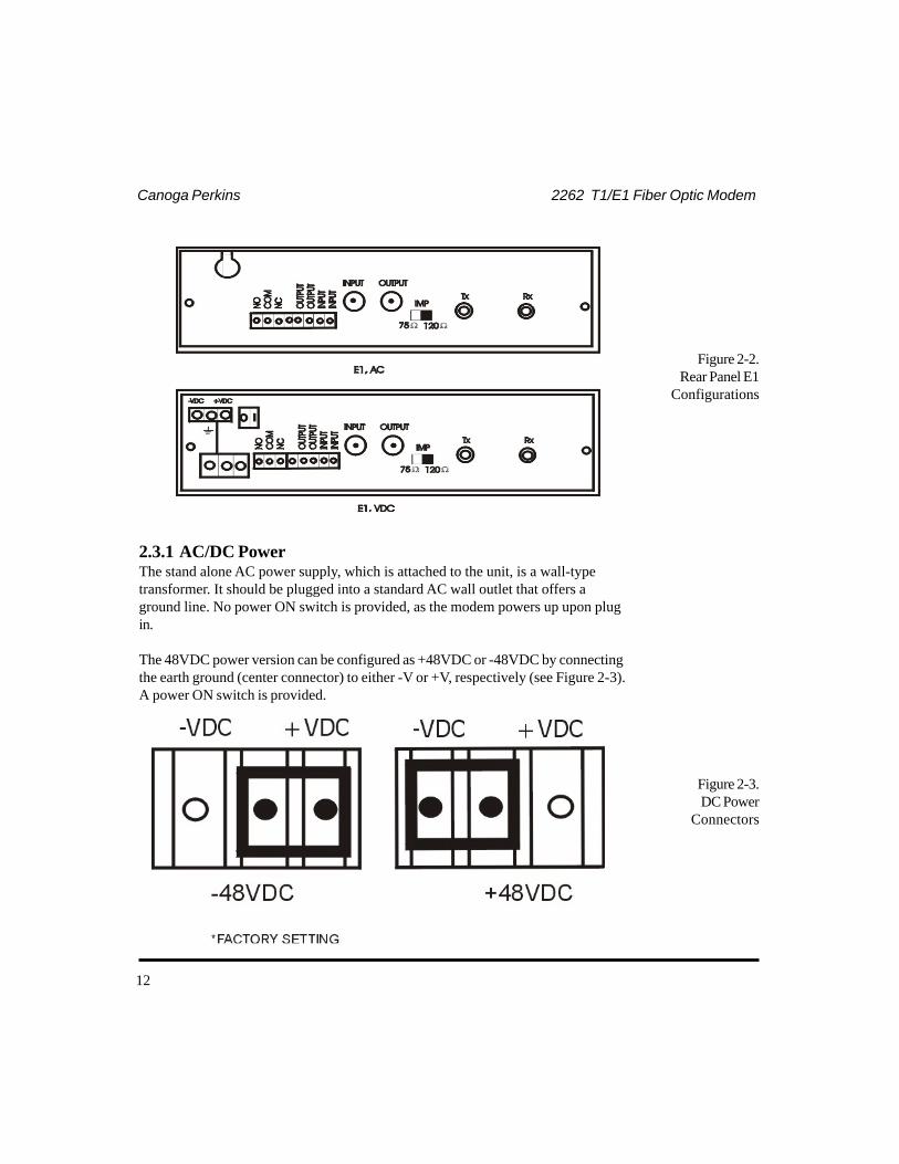
Figure 2-2.Rear Panel E1
Configurations
2.3.1 AC/DC PowerThe stand alone AC power supply, which is attached to the unit, is a wall-typetransformer. It should be plugged into a standard AC wall outlet that offers aground line. No power ON switch is provided, as the modem powers up upon plugin.
The 48VDC power version can be configured as +48VDC or -48VDC by connectingthe earth ground (center connector) to either -V or +V, respectively (see Figure 2-3).A power ON switch is provided.
Figure 2-3.DC Power
Connectors

13
2262 T1/E1 Fiber Optic Modem Canoga Perkins
2.3.2 Interface ConnectorsThree different interface connectors, located on the rear panel (see Figure 2-4), areavailable for the 2262.For T1:• DA-15/RJ-48C or• Terminal Block/RJ-48C
For E1:• BNC and Terminal Block
Figure 2-4.2262 InterfaceConnectors

14
Canoga Perkins 2262 T1/E1 Fiber Optic Modem
2.3.3 Alarm Relay ConnectorsThe Alarm Relay Connection shares the DA-15 or terminal block. See Figure 2-4 fordetails.
2.3.4 E1 Impedance SwitchAn impedance switch is provided to select either 75Ω (BNC connectors) or 120Ω(terminal block) for E1 models only. On stand alone models, this switch is locatedon the rear panel.
On rack-chassis models, the switch is located at the rear printed circuit board edge,above the optic transmitter connector. The Up setting is for 75Ω; the Down settingis for 120Ω.
2.3.5 Loopback SwitchThe Loopback switch (located on the front panel) is to be set in the Off position fornormal operations.
2.4 Rack Mount InstallationThe 2201 Rack Chassis is designed to accommodate up to ten 2262 modems; seeFigure 2-5. The 2201 will fit into a standard 19-inch equipment rack. Tabs areprovided on each side of the unit and are predrilled for standard spacing. Forfurther details, refer to the 2201 Rack Chassis User Manual.
Figure 2-5.2201 Rack Chassis

15
2262 T1/E1 Fiber Optic Modem Canoga Perkins
3. OperationDuring normal operation, the 2262 receives input data at the metallic interface andmodulates it into an optic signal. It also detects the optic input signals, demodu-lates them back into the original T1 or E1 data stream, and retransmits output dataat the metallic interface.
The 2262 lights the Tx LED (see Figure 3-1) when data pulses are detected from theInput leads, and lights the Rx LED when data pulses are transmitted at the Outputleads. When the 2262 fails to receive optic signals, the alarm relay will bedeenergized and the relay contact status will be changed.
Figure 3-1.2262 Front Panel
3.1 Local Loopback OperationWhen the 2262 Loopback Switch is set to Loc, the Loopback LED will light and the2262 will operate in the local loopback mode. During this operation, the datareceived from the Input leads will be looped directly back into the Output leads.The Tx and Rx LEDs will be lit as data pulses are presented on those leads. Thereceived optical data will be demodulated then remodulated. It will then be transmit-ted back out as transmit optical data. The relay contact status will stay normal aslong as optical pulses are presented at the optical Rx port.
3.2 Remote Loopback OperationWhen the 2262 Loopback Switch is set to Rem, the Loopback LED will light and the2262 will then operate in the remote loopback mode. During this operation, thetransmitted optical signals at the optical Tx port will be further encoded to carry aremote loopback protocol.

16
Canoga Perkins 2262 T1/E1 Fiber Optic Modem
The 2262 at the remote side will detect the remote loopback protocol and set itselfinto a local loopback mode. The remote unit will also light its loopback LED(blinking). The loopback switch at the remote side must remain in the Off position;otherwise, the loopback operation at both local and remote sides will be terminated.
Figure 3-2, 2262 Block Diagram, shows the various operation modes and signalflows.
Figure 3-2.2262 Block
Diagram
17
2262 T1/E1 Fiber Optic Modem Canoga Perkins
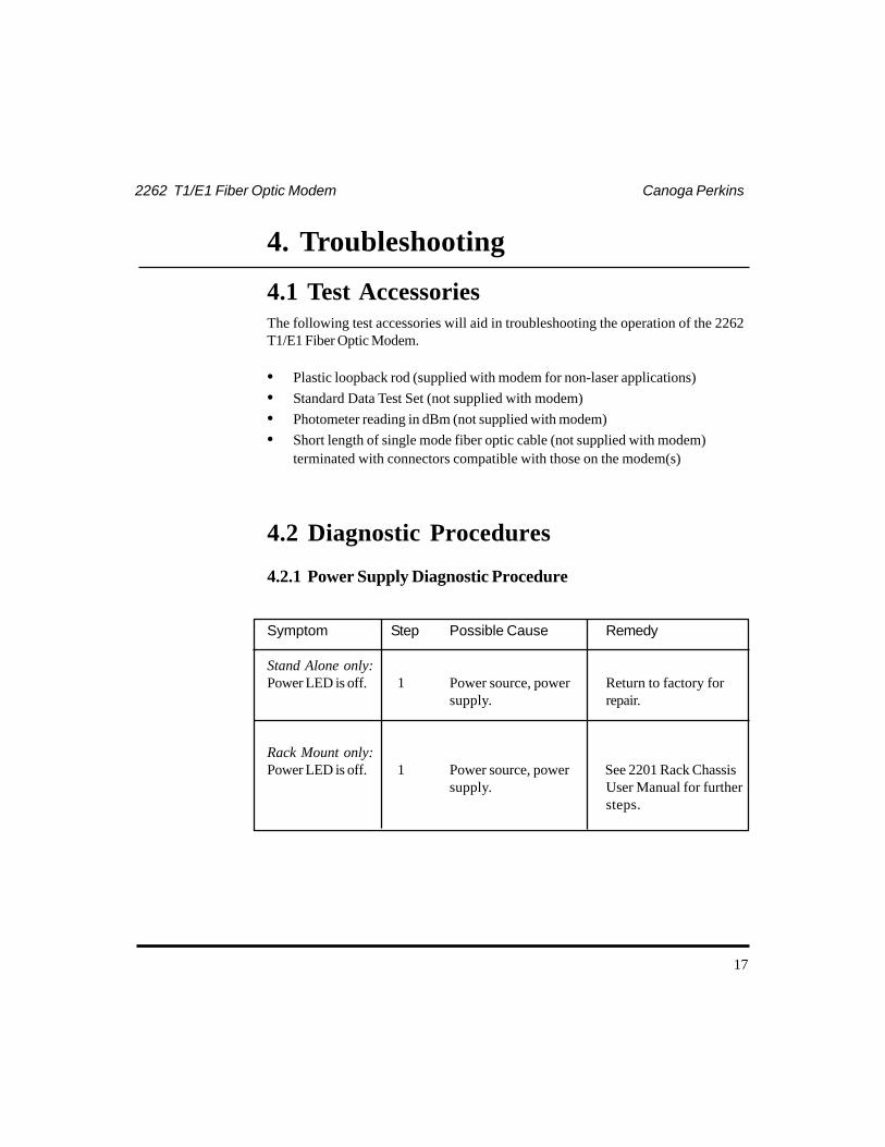
4. Troubleshooting
4.1 Test AccessoriesThe following test accessories will aid in troubleshooting the operation of the 2262T1/E1 Fiber Optic Modem.
• Plastic loopback rod (supplied with modem for non-laser applications)• Standard Data Test Set (not supplied with modem)• Photometer reading in dBm (not supplied with modem)• Short length of single mode fiber optic cable (not supplied with modem)
terminated with connectors compatible with those on the modem(s)
4.2 Diagnostic Procedures
4.2.1 Power Supply Diagnostic Procedure
Symptom Step Possible Cause Remedy
Stand Alone only:Power LED is off. 1 Power source, power Return to factory for
supply. repair.
Rack Mount only:Power LED is off. 1 Power source, power See 2201 Rack Chassis
supply. User Manual for furthersteps.

18
Canoga Perkins 2262 T1/E1 Fiber Optic Modem
4.2.2 Link Diagnostic Procedure
Symptom Step Possible Cause Remedy
Tx LED is off 1 Reversed data input and Swap T1/E1 data inputoutput connection. and output cable
connection.
2 No data input at See Section 4.2.3,metallic interface. Loopback Diagnostic
Procedure, step 1.
Tx LED is off 3 Unit failed. Return to factory forrepair.
Rx LED is off 1 Reversed optic transmit Swap the optic transmitand receive connection. and receive cable
connection.
2 Local or remote side See Section 4.2.3,system or fiber optic Loopback Diagnosticlink failure. Procedure, steps 2 to 4.
High error rate 1 Bad optical connection. Clean the optic connec-tor end surface.
2 Local or remote side See Section 4.2.3,system or fiber optic Loopback Diagnosticlink failure. Procedure, steps 1 to 4.

19
2262 T1/E1 Fiber Optic Modem Canoga Perkins
4.2.3 Loopback Diagnostic Procedure
Symptom Step Possible Cause Remedy
Set loopback switch 1 Local data source failed. Correct the local datato local mode and source.error is not corrected.
Disable loopback 2 Unit failed. Return to factory forfunction and use repair.plastic loopbackrod (for multimode)or short length ofoptic cable (for singlemode) to loop thelocal optic interfacewhen error is notcorrected.
Set loopback switch 3 Bad optic link. Repair the bad fiberto remote mode and optic cables.error is not corrected.
All above steps are 4 Remote system failed. Correct the remoteunable to correct system.errors.

20
Canoga Perkins 2262 T1/E1 Fiber Optic Modem
This page is intentionally blank

21
2262 T1/E1 Fiber Optic Modem Canoga Perkins
5. Technical Specifications
5.1 Physical and EnvironmentalDimensions:
Stand Alone 12.2" L x 8.4" W x 1.75" HRack Mount Card 12.0" L x 7.8" W x 1.06" H
Weight:Stand Alone 3.6lbs
Rack Mount Card 0.9 lbs
Operating Environment:Temperature 0 to 55°CHumidity 0 to 95% (non-condensing)Storage -10 to 65°C
Power: 115VAC ±10%, 50-60Hz115VAC ±10% / 240VAC +10/-15%, 50-60Hz48VDC36-72VDC
LEDs:Tx Transmit (green)Rx Receive (green)Pwr Power (green)Loopback Loopback On (red)
Switches:Loopback (front) Three-position: Rem, Off, LocImpedance (E1 only) 75Ω / 120Ω(rear)

22
Canoga Perkins 2262 T1/E1 Fiber Optic Modem
5.2 OpticalTransmitter: LED (850nm) ST multimode
Laser (1310nm) ST or FC single mode
Loss Budget:LED 15dBmLaser 20dBm
Power Rates:LED Launch power: -14dBm
Sensitivity: -29dBmOverdrive: none
Laser Launch power: -6dBmSensitivity: -26dBmOverdrive: none
NOTE: To measure the optical power, data must be present at thedata input leads.
5.3 T1/E1 InterfaceConnectors:
T1 DA-15 (female)/RJ-48C or terminal block/RJ-48C,with alarm
E1 BNC (two female) and terminal block (withalarm)
Impedance:T1 100ohmE1 Switchable 75ohm / 120ohm
Input Selectivity:T1 -6dBE1 -6dB
Output Signal Level:T1 6V p-p ±1.4VE1 75Ω 4.74V p-p ±10%
120Ω 6V p-p ±10%

23
2262 T1/E1 Fiber Optic Modem Canoga Perkins
Line Codes: Transparent to AMI, B8ZS and HDB3 (passesbipolar violations)
Data Rates: 1.544Mbps (T1), 2.048Mbps (E1)
5.4 Agency Certification
• FCC, Part 15 class A (stand alone version)• Safety Standards (stand alone and rack mount versions):
• UL 1950• CSA 950
• Austel TS 016-1990 (2.048MHz, stand alone version)• TS 001• AS-3548
5.5 Connector Pinout
Signal DA-15 Terminal Strip RJ-48CPin Pin
INPUT 1 8 IN 4INPUT 9 7 IN 5OUTPUT 3 6 OUT 1OUTPUT 11 5 OUT 2ALARM NC 7 3ALARM COM 15 2ALARM NO 8 1

24
Canoga Perkins 2262 T1/E1 Fiber Optic Modem
6. 2262 GlossaryBNC Bayonet Connector
CAD/CAM Computer-Aided Design/Computer-AidedManufacturing
Collimation The process by which a divergent or conver-gent beam of radiation is converted into a beamwith the minimum divergence possible for thatsystem (ideally, a parallel bundle of rays).
CSU Channel Service Unit
dB Decibel. A standard unit used to express gainor loss of optical power.
E1 Transmission at 2.048Mbps.
FC Fiber Optic Connector (developed by NTT)
LED Light Emitting Diode. A semiconductordevice which emits incoherent light formed atthe -N junction, either from the junction stripeedge or its surface.
Multimode Fiber An optical fiber with a core diameter of 25 to200 microns. The core is much larger thansingle mode fiber and allows several beams oflight to be passed through it.
nm nanometer (10-9 meters)
PBX Private Branch Exchange

25
2262 T1/E1 Fiber Optic Modem Canoga Perkins
Single Mode Fiber A fiber waveguide that supports the propaga-tion of only one wavelength. Usually a low-loss optical waveguide with a very small core(2 to 9 microns). It requires a laser source forthe input signals because of the very smallentrance aperture (acceptance cone). The smallcore radius approaches the wavelength of thesource; consequently, only a single wavelength is propagated.
ST Straight-Through Fiber Optic Connector(developed by AT&T)
T1 Transmission at 1.544Mbps.

26
Canoga Perkins 2262 T1/E1 Fiber Optic Modem
Appendix A
Limited Warranty
A.1 ProductsCanoga Perkins warrants that, at the time of sale, its products will be freefrom defects in material and workmanship, and if properly installed andused will substantially conform to Canoga Perkins' published specifications.Subject to the conditions and limitations set forth below, Canoga Perkinswill, at its opinion, either repair or replace any part of its product(s) thatprove defective by use of improper worksmanship or materials. Thiswarranty does not cover any damage to products that have been subjectedto lightning damage or other Acts of Nature, misuse, neglect, accident,damage, improper installation or maintenance, or alteration or repair byanyone other thanCanoga Perkins or its authorized representative. Cus-tomer must notify Canoga Perkins promptly in writing of any claim basedon warranty. Canoga Perkins is not liable for, and does not cover underwarranty, any costs associated with service and/or the installation of itsproducts of for any inspection, packig or labor costs in connectionwithreturn of goods. In the event Canoga Perkins breaches its obligation ofwarranty, customer's sole and exclusive remedy is limited to replacement,repair, or credit of the purchase price, at Canoga Perkins' option.
A.2 Duration of WarrantyThree-year Warranty: This product is covered by this warranty for a periodof three (3) years from the date of shipment.
A.3 LimitationsCanoga Perkins may at its sole discretion modify its Limited Warranty atany time and from time to time.
27
2262 T1/E1 Fiber Optic Modem Canoga Perkins
Other than those expressly stated herein, THERE ARE NO OTHERWARRANTIES OF ANY KIND, EXPRESSED OR IMPLIED, ANDSPECIFICALLY EXCLUDED BUT NOT BY WAY OF LIMITATION,ARE THE IMPLIED WARRANTIES FOR FITNESS FOR A PARTICU-LAR PURPOSE AND MERCHANTABILITY. IT IS UNDERSTOODAND AGREED CANOGA PERKINS' LIABILITY WHETHER INCONTRACT, IN TORT, UNDER ANY WARRANTY, IN NEGLI-GENCE OR OTHERWISE SHALL NOT EXCEED THE AMOUNT OFTHE PURCHASE PRICE PAID BY THE PURCHASER AND UNDERNO CIRCUMSTANCES SHALL CANOGA PERKINS BE LIABLEFOR SPECIAL, INDIRECT, INCIDENTAL OR CONSEQUENTIALDAMAGES. THE PRICE STATED FOR THE EQUIPMENT IS ACONSIDERATION IN LIMITING CANOGA PERKINS' LIABILITY.NO ACTION, REGARDLESS OF FORM, ARISING OUT OF THETRANSACTIONS OF THIS AGREEMENT MAY BE BROUGHT BYPURCHASER MORE THAN ONE YEAR AFTER THE CAUSE OFTHE ACTION HAS ACCRUED. CANOGA PERKINS' MAXIMUMLIABILITY SHALL NOT EXCEED AND CUSTOMER'S REMEDY ISLIMITED TO EITHER (i) REPAIR OR REPLACEMENT OF THEDEFECTIVE PART OF PRODUCT, OR AT CANOGA PERKINS'OPTION (ii) RETURN OF THE PRODUCT AND REFUND OF THEPURCHASE PRICE, AND SUCH REMEDY SHALL BECUSTOMER'S ENTIRE AND EXCLUSIVE REMEDY.
A.4 Customer Service Department Repair WarrantyRepairs performed by the Canoga Perkins Customer Service Departmentwill be free from defects in material and workmanship for a period of ninety(90) DAYS from the date the repaired product is shipped, or until theexpiration of the original factory warranty, whichever is longer.
Shipping charges to Canoga Perkins will be at customer's expense. Unitswill be returned to the customer FOB origin. Repaired units will be returnedto the customer by standard ground shipment unless otherwise specified,with any additional costs for customer specified expedited delivery at thecustomer's expense.