2005-01-11 ieee c802.16e-04/552r4 project ieee 802.16 ...2005-01-11 ieee c802.16e-04/552r4 framework...
TRANSCRIPT
2005-01-11 IEEE C802.16e-04/552r4
Project IEEE 802.16 Broadband Wireless Access Working Group <http://ieee802.org/16>
Title Framework for Enabling Closed-loop MIMO for OFDMA
Date Submitted
2005-01-11
Source(s) Wonil Roh, JeongTae Oh, Chan-Byoung Chae, Kyunbyoung Ko, Hongsil Jeong, Sung-Ryul Yun, Seungjoo Maeng, Jaeho Jeon, Jaeyeol Kim, Soonyoung Yoon
Samsung Electronics Co., Ltd.
Erik Lindskog, Harold Artes, Djordje Tujkovic, Kamlesh Rath, Andreas Bergkvist, V. Shashidhar, B. Sundar Rajan, Rahul Vaze, Bob Lorenz, Babu Mandava, A. Paulraj, Aditya Agrawal
Beceem Communications, Inc.
Young-Ho Jung, Seung Hoon Nam , Jaehak Chung, Yungsoo Kim, Sung-Jin Kim, Hojin Kim
Samsung Advanced Institute of Technology
Wen Tong, Peiying Zhu, Ming Jia, Dongsheng Yu, Hua Xu, Jianglei Ma ,Mo-Han Fong, Hang Zhang, Brian Johnson Nortel Networks Qinghua Li, Xintian Eddie Lin, Shilpa Talwar, Randall Schwartz, Sumeet Sandhu Intel Corporation Bin-Chul Ihm, Yongseok Jin, Jinyoung Chun, Kyuhyuk Chung LG Electronics Kevin Baum, Mark Cudak, Tim Thomas, Fred Vook Xiangyang (Jeff) Zhuang Motorola Labs Jing Wang, Sean Cai, Jason Hou, Mary Chion, Dazi Feng
Voice: +82-31-279-3868
Voice: +1-408-387-5014
2005-01-11 IEEE C802.16e-04/552r4
ZTE San Diego Inc. Jianzhong (Charlie) Zhang, Anthony Reid, Kiran Kuchi, Nico Van Waes, Victor Stolpman Nokia Muhammad Ikram, Eko Onggosanusi, Vasanthan Raghavan, Anand Dabak, Srinath Hosur, and Badri Varadarajan Texas Instruments Mattias Wennstrom, Branislav Popovic Huawei Technologies Young Seog Song, Seung Joon Lee, Dong Seung Kwon ETRI Korea Masoud Olfat Nextel Communications
Re:
Abstract Framework for Enabling Closed-loop MIMO for OFDMA
Purpose Adoption of proposed changes into P802.16e
Crossed-out indicates deleted text, underlined blue indicates new text change to the Standard
Notice This document has been prepared to assist IEEE 802.16. It is offered as a basis for discussion and is not binding on the contributing individual(s) or organization(s). The material in this document is subject to change in form and content after further study. The contributor(s) reserve(s) the right to add, amend or withdraw material contained herein.
Release The contributor grants a free, irrevocable license to the IEEE to incorporate material contained in this contribution, and any modifications thereof, in the creation of an IEEE Standards publication; to copyright in the IEEE’s name any IEEE Standards publication even though it may include portions of this contribution; and at the IEEE’s sole discretion to permit others to reproduce in whole or in part the resulting IEEE Standards publication. The contributor also acknowledges and accepts that this contribution may be made public by IEEE 802.16.
Patent Policy and Procedures
The contributor is familiar with the IEEE 802.16 Patent Policy and Procedures (Version 1.0) <http://ieee802.org/16/ipr/patents/policy.html>, including the statement “IEEE standards may include the known use of patent(s), including patent applications, if there is technical justification in the opinion of the standards-developing committee and provided the IEEE receives assurance from the patent holder that it will license applicants under reasonable terms and conditions for the purpose of implementing the standard.” Early disclosure to the Working Group of patent information that might be relevant to the standard is essential to reduce the possibility for delays in the development process and increase the likelihood that the draft publication will be approved for publication. Please notify the Chair <mailto:[email protected] > as early as possible, in

2005-01-11 IEEE C802.16e-04/552r4
written or electronic form, of any patents (granted or under application) that may cover technology that is under consideration by or has been approved by IEEE 802.16. The Chair will disclose this notification via the IEEE 802.16 web site <http://ieee802.org/16/ipr/patents/notices>.
2005-01-11 IEEE C802.16e-04/552r4
Framework for Enabling Closed-loop MIMO for OFDMA
1. Introduction In this contribution, a framework which enables closed-loop MIMO (CL-MIMO) for OFDMA systems is provided. A suite of solutions is described in this document in order to cover various channel conditions and operational scenarios. The suite of solutions includes antenna selection, antenna grouping, vector/matrix codebooks, and direct channel coefficient feedback. It includes redefinition of CQICH feedback mechanism, the required changes of payload, and clarification of precoding operation and the necessary text changes on the relevant sections in the standard. The organization of the contribution is shown as follows 1. Introduction .................................................................................................................................................................... 3 2. MIMO Related Basic Capabilities ................................................................................................................................ 3 3. CQICH Signaling for CL-MIMO ................................................................................................................................. 4 4. MIMO Precoding ......................................................................................................................................................... 11 5. MIMO Precoding Operation for H-ARQ MAP ........................................................................................................ 14 6. Direct Channel Coefficient Feedback
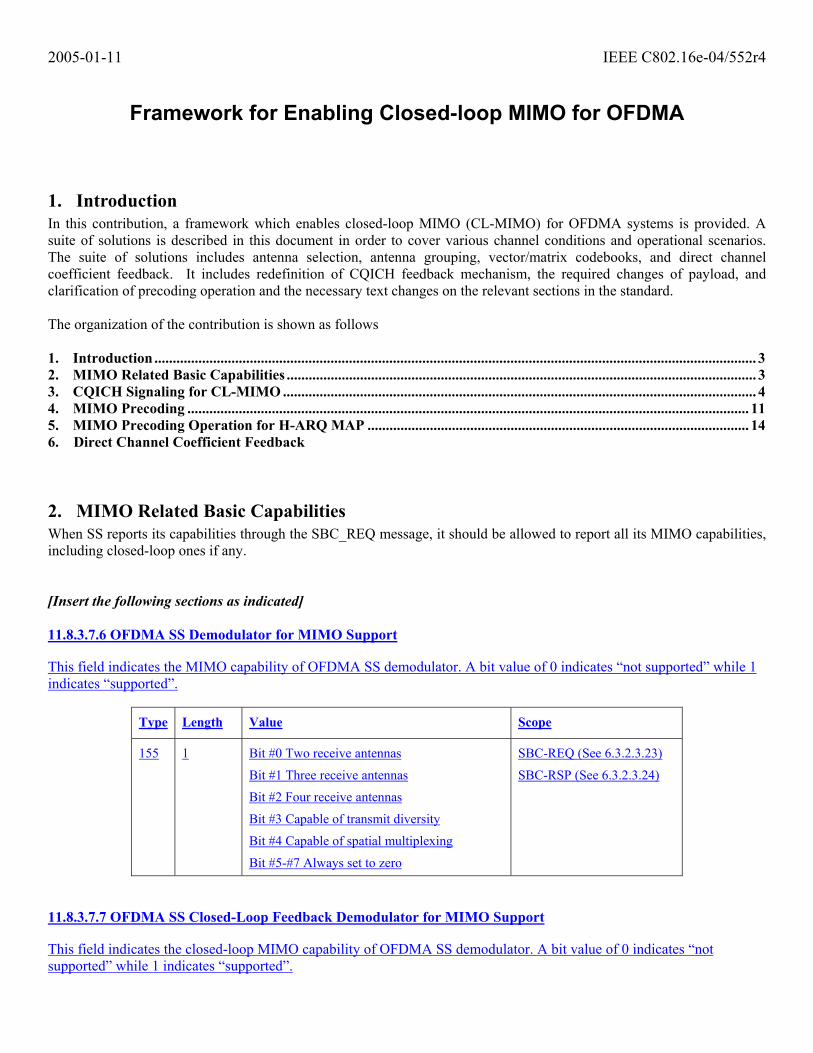
2. MIMO Related Basic Capabilities When SS reports its capabilities through the SBC_REQ message, it should be allowed to report all its MIMO capabilities, including closed-loop ones if any. [Insert the following sections as indicated] 11.8.3.7.6 OFDMA SS Demodulator for MIMO Support This field indicates the MIMO capability of OFDMA SS demodulator. A bit value of 0 indicates “not supported” while 1 indicates “supported”.
Type Length Value Scope
155 1 Bit #0 Two receive antennas
Bit #1 Three receive antennas
Bit #2 Four receive antennas
Bit #3 Capable of transmit diversity
Bit #4 Capable of spatial multiplexing
Bit #5-#7 Always set to zero
SBC-REQ (See 6.3.2.3.23)
SBC-RSP (See 6.3.2.3.24)
11.8.3.7.7 OFDMA SS Closed-Loop Feedback Demodulator for MIMO Support This field indicates the closed-loop MIMO capability of OFDMA SS demodulator. A bit value of 0 indicates “not supported” while 1 indicates “supported”.
2005-01-11 IEEE C802.16e-04/552r4
Type Length Value Scope
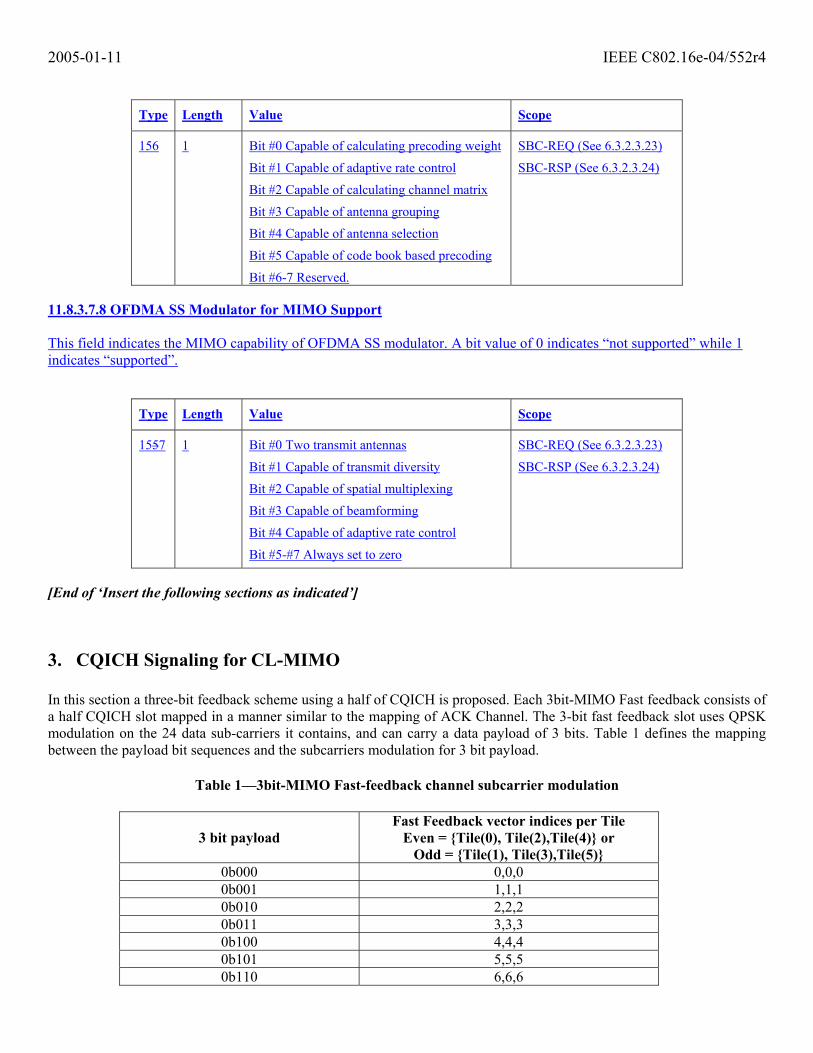
156 1 Bit #0 Capable of calculating precoding weight
Bit #1 Capable of adaptive rate control
Bit #2 Capable of calculating channel matrix
Bit #3 Capable of antenna grouping
Bit #4 Capable of antenna selection
Bit #5 Capable of code book based precoding
Bit #6-7 Reserved.
SBC-REQ (See 6.3.2.3.23)
SBC-RSP (See 6.3.2.3.24)
11.8.3.7.8 OFDMA SS Modulator for MIMO Support This field indicates the MIMO capability of OFDMA SS modulator. A bit value of 0 indicates “not supported” while 1 indicates “supported”.
Type Length Value Scope
1557 1 Bit #0 Two transmit antennas
Bit #1 Capable of transmit diversity
Bit #2 Capable of spatial multiplexing
Bit #3 Capable of beamforming
Bit #4 Capable of adaptive rate control
Bit #5-#7 Always set to zero
SBC-REQ (See 6.3.2.3.23)
SBC-RSP (See 6.3.2.3.24)
[End of ‘Insert the following sections as indicated’]
3. CQICH Signaling for CL-MIMO In this section a three-bit feedback scheme using a half of CQICH is proposed. Each 3bit-MIMO Fast feedback consists of a half CQICH slot mapped in a manner similar to the mapping of ACK Channel. The 3-bit fast feedback slot uses QPSK modulation on the 24 data sub-carriers it contains, and can carry a data payload of 3 bits. Table 1 defines the mapping between the payload bit sequences and the subcarriers modulation for 3 bit payload.
Table 1—3bit-MIMO Fast-feedback channel subcarrier modulation
3 bit payload Fast Feedback vector indices per Tile
Even = {Tile(0), Tile(2),Tile(4)} or Odd = {Tile(1), Tile(3),Tile(5)}
0b000 0,0,0 0b001 1,1,1 0b010 2,2,2 0b011 3,3,3 0b100 4,4,4 0b101 5,5,5 0b110 6,6,6

2005-01-11 IEEE C802.16e-04/552r4
0b111 7,7,7
Figure 1 Channel Performance of 3-bit CQICH
FAST_FEEDBACK_Channel Performance ( 2 Rx Antenna)
1.0E- 04
1.0E- 03
1.0E- 02
1.0E- 01
1.0E+00
- 10 - 8 - 6 - 4 - 2SINR(dB)
FAST
_FE
ED
BA
CK
_Pac
ket E
rror
6 bit (1 CQICH), AWGN
6 bit (1 CQICH), Ped B 3km/ h
3 bit (1/ 2 CQICH), AWGN
3 bit (1/ 2 CQICH), Ped B 3km
[Modify Section 8.4.5.4.10.4 as indicated in the following] 8.4.5.4.10.4 Optional Enhanced FAST FEEDBACK Channels Enhanced Fast feedback slots may be individually allocated to an MSS for transmission of PHY related information that requires fast response from the MSS. The allocations are done either in a unicast manner through the FAST_FEEDBACK MAC subheader (see 6.3.2.2.6), or through the CQICH_Control IE() (see 6.3.2.3.43.5), or through the CQICH_Alloc_IE() (see 8.4.5.4.12), or through the CQICH_Enhanced_Alloc_IE() (see 8.4.5.4.12.1), or through the MIMO Compact DL-MAP IE() (see 6.3.2.3.43.6.7), and the transmission takes place in a specific UL region designated by UIUC = 0. Each enhanced 3bit-MIMO Fast-feedback slot consists of 1/2 OFDMA slots mapped in a manner similar to the mapping of ACK Channel. An enhanced Fast-feedback slot uses QPSK modulation on the 24 data sub-carriers it contains, and can carry a data payload of 3 bits. Table xxx defines the mapping between the payload bit sequences and the subcarriers modulation.
Table xxx—3bit-MIMO Fast-feedback channel subcarrier modulation
3 bit payload Fast Feedback vector indices per Tile
Even = {Tile(0), Tile(2),Tile(4)} or Odd = {Tile(1), Tile(3),Tile(5)}
0b000 0,0,0 0b001 1,1,1 0b010 2,2,2 0b011 3,3,3

2005-01-11 IEEE C802.16e-04/552r4
0b100 4,4,4 0b101 5,5,5 0b110 6,6,6 0b111 7,7,7
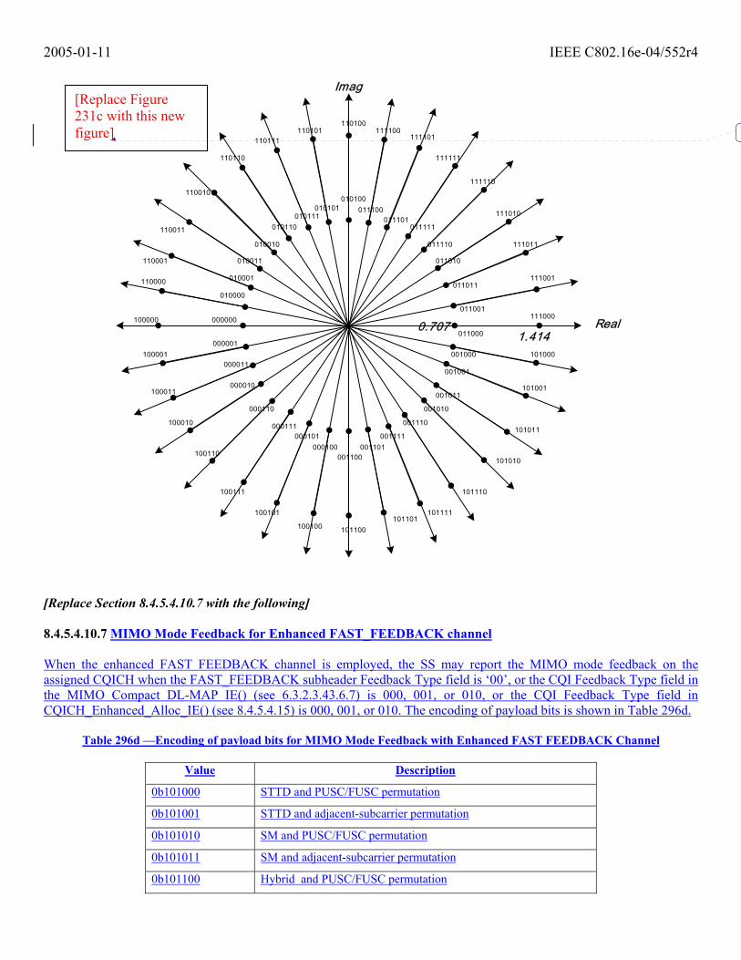
Each enhanced Fast-feedback slot consists of 1 OFDMA slots mapped in a manner similar to the mapping of normal uplink data. An enhanced Fast-feedback slot uses QPSK modulation on the 48 data sub-carriers it contains, and can carry a data payload of 6 bits. Table 296a defines the mapping between the payload bit sequences and the subcarriers modulation. [Modify Section 8.4.5.4.10.6 as suggested in the following] 8.4.5.4.10.6 Fast MIMO Feedback of Quantized Precoding Weight for Enhanced FAST_FEEDBACK Channel When the FAST_FEEDBACK subheader Feedback Type field is ‘01’ or ‘10’, or the CQI Feedback Type field in the MIMO Compact DL-MAP IE() (see 6.3.2.3.43.6.7) is 011, or the CQI Feedback Type field in CQICH_Enhanced_Alloc_IE() (see 8.4.5.4.1512.1) is 011, the MSS shall report the MIMO coefficient the BS should use for best DL reception (see 8.4.8.1.6). The mapping for the complex weights is shown in Figure 231c, and the SS shall construct the 6 CQI bits with 0 as the MSB and the mapped code as the remaining LSBs. For this type of feedback, if N is the number of BS transmit antennas, then (N-1) CQICH shall be allocated to the SS and SS shall report the desired antenna weights of antenna 1 through N-1 based on antenna 0. Figure 231c - Mapping of MIMO coefficients for quantized precoding weight for enhanced fast MIMO feedback payload bits
2005-01-11 IEEE C802.16e-04/552r4
000000
000001
000011
000010
000110
000111000101
000100001100
001101
001000
001001
001011
001010
001110
001111
010000
010001
010011
010010
010110010111
010101010100
011100011101
011111
011110
011010
011011
011001
011000Real
Imag
100000
100001
100011
100010
100110
100111
100101
100100101101
101100
101111
101110
101010
101011
101001
101000
111000
111001
111011
111010
111110
111111
111101111100
110100110101
110111
110110
110010
110011
110001
110000
1.4140.707
[Replace Section 8.4.5.4.10.7 with the following] 8.4.5.4.10.7 MIMO Mode Feedback for Enhanced FAST_FEEDBACK channel When the enhanced FAST FEEDBACK channel is employed, the SS may report the MIMO mode feedback on the assigned CQICH when the FAST_FEEDBACK subheader Feedback Type field is ‘00’, or the CQI Feedback Type field in the MIMO Compact DL-MAP IE() (see 6.3.2.3.43.6.7) is 000, 001, or 010, or the CQI Feedback Type field in CQICH_Enhanced_Alloc_IE() (see 8.4.5.4.15) is 000, 001, or 010. The encoding of payload bits is shown in Table 296d.
Table 296d —Encoding of payload bits for MIMO Mode Feedback with Enhanced FAST FEEDBACK Channel
Value Description
0b101000 STTD and PUSC/FUSC permutation
0b101001 STTD and adjacent-subcarrier permutation
0b101010 SM and PUSC/FUSC permutation
0b101011 SM and adjacent-subcarrier permutation
0b101100 Hybrid and PUSC/FUSC permutation
[Replace Figure 231c with this new figure]

2005-01-11 IEEE C802.16e-04/552r4
0b101101 Hybrid and adjacent-subcarrier permutation
0b101110-0b110110
Interpretation according to table 296e, 296f or 296g, depending on if antenna grouping, antenna selection or a reduced precoding matrix code book is used.
0b110111 Closed loop precoding with 1 stream.
0b111000 Closed loop precoding with 2 streams.
0b111001 Closed loop precoding with 3 streams.
0b111010 Closed loop precoding with 4 streams.
0b111011 - 0b111111
Reserved
Clarification of streams concept: The number of streams is the number of outputs from the space-time code.
Table 296e —Interpretation of code words 0b101110-0b110110 in Table 296d in the case of using antenna grouping
Value Description
0b101110 Antenna Group A1 for rate 1 For 3-antenna BS, See 8.4.8.3.4 For 4-antenna BS, See 8.4.8.3.5
0b101111 Antenna Group A2 for rate 1
0b110000 Antenna Group A3 for rate 1
0b110001 Antenna Group B1 for rate 2 For 3-antenna BS, See 8.4.8.3.4 For 4-antenna BS, See 8.4.8.3.5
0b110010 Antenna Group B2 for rate 2
0b110011 Antenna Group B3 for rate 2
0b110100 Antenna Group B4 for rate 2 (only for 4-antenna BS)
0b110101 Antenna Group B5 for rate 2 (only for 4-antenna BS)
0b110110 Antenna Group B6 for rate 2 (only for 4-antenna BS)
Table 296f —Interpretation of code words 0b101110-0b110110 in Table 296d in the case of using antenna selection
Value Description
0b101110 Antenna selection option 0 0b101111 Antenna selection option 1
0b110000 Antenna selection option 2
0b110001 Antenna selection option 3
0b110010 Antenna selection option 4
0b110011 Antenna selection option 5
0b110100 Antenna selection option 6

2005-01-11 IEEE C802.16e-04/552r4
0b110101 Antenna selection option 7
0b110110 Reserved
Table 296g —Interpretation of code words 0b101110-0b110110 in Table 296d in the case of using reduced precoding matrix code book
Value Description
0b101110 Reduced Precoding matrix code book entry 0
0b101111 Reduced Precoding matrix code book entry 1
0b110000 Reduced Precoding matrix code book entry 2
0b110001 Reduced Precoding matrix code book entry 3
0b110010 Reduced Precoding matrix code book entry 4
0b110011 Reduced Precoding matrix code book entry 5
0b110100 Reduced Precoding matrix code book entry 6
0b110101 Reduced Precoding matrix code book entry 7
0b110110 Reserved
[End of “Replace Section 8.4.5.4.10.7 with the following”] [Remove the entire Section 8.4.5.4.10.8] 8.4.5.4.10.8 MIMO related Type Independent Feedback for enhanced FAST_FEEDBACK channel For 6 bit payload case, MIMO related feedback shall be encoded as is shown in Table 294d .
Table 297 —Encoding of payload bits for MIMO feedback with 6 bit payload
Value Description
0b101000 STC and PUSC/FUSC permutation
0b101001 STC and adjacent-subcarrier permutation
0b101010 SM and PUSC/FUSC permutation
0b101011 SM and adjacent-subcarrier permutation
0b101100 Closed-loop SM and PUSC/FUSC permutation
0b101101 Closed-loop SM and adjacent-subcarrier permutation
0b101110 Hybrid and PUSC/FUSC permutation
0b101111 Hybrid and adjacent-subcarrier permutation
0b110000 Beamforming and adjacent-subcarrier permutation
0b110001 Antenna Group A For 3-antenna BS, 00 = Antenna group 0,1 & 0,2 For 4-antenna BS, 00 = Antenna group 0,1 & 2,3
0b110010 Antenna Group BFor 3-antenna BS, 00 = Antenna group 0,1 & 1,2 For 4-antenna BS, 00 = Antenna group 0,2 & 1,3
2005-01-11 IEEE C802.16e-04/552r4
0b110011 Antenna Group CFor 3-antenna BS, 00 = Antenna group 0,2 & 1,2 For 4-antenna BS, 00 = Antenna group 0,3 & 1,2
0b110100 - 0b111111
Reserved
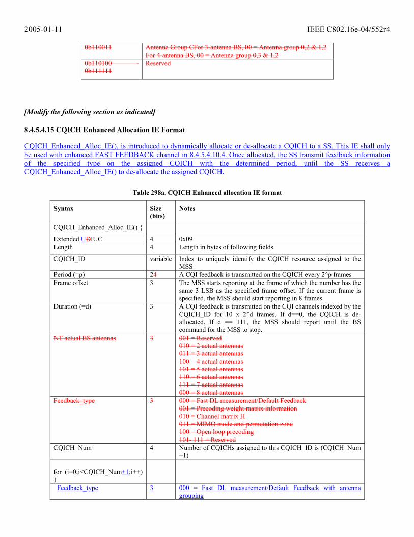
[Modify the following section as indicated] 8.4.5.4.15 CQICH Enhanced Allocation IE Format CQICH_Enhanced_Alloc_IE(), is introduced to dynamically allocate or de-allocate a CQICH to a SS. This IE shall only be used with enhanced FAST FEEDBACK channel in 8.4.5.4.10.4. Once allocated, the SS transmit feedback information of the specified type on the assigned CQICH with the determined period, until the SS receives a CQICH_Enhanced_Alloc_IE() to de-allocate the assigned CQICH.
Table 298a. CQICH Enhanced allocation IE format
Syntax Size (bits)
Notes
CQICH_Enhanced_Alloc_IE() {
Extended UDIUC 4 0x09 Length 4 Length in bytes of following fields
CQICH_ID variable Index to uniquely identify the CQICH resource assigned to the MSS
Period (=p) 24 A CQI feedback is transmitted on the CQICH every 2^p frames Frame offset 3 The MSS starts reporting at the frame of which the number has the
same 3 LSB as the specified frame offset. If the current frame is specified, the MSS should start reporting in 8 frames
Duration (=d) 3 A CQI feedback is transmitted on the CQI channels indexed by the CQICH_ID for 10 x 2^d frames. If d==0, the CQICH is de-allocated. If d == 111, the MSS should report until the BS command for the MSS to stop.
NT actual BS antennas 3 001 = Reserved 010 = 2 actual antennas 011 = 3 actual antennas 100 = 4 actual antennas 101 = 5 actual antennas 110 = 6 actual antennas 111 = 7 actual antennas 000 = 8 actual antennas
Feedback_type 3 000 = Fast DL measurement/Default Feedback 001 = Precoding weight matrix information 010 = Channel matrix H 011 = MIMO mode and permutation zone 100 = Open loop precoding 101- 111 = Reserved
CQICH_Num 4 Number of CQICHs assigned to this CQICH_ID is (CQICH_Num +1)
for (i=0;i<CQICH_Num+1;i++) {
Feedback_type 3 000 = Fast DL measurement/Default Feedback with antenna grouping
2005-01-11 IEEE C802.16e-04/552r4
001 = Fast DL measurement/Default Feedback with antenna selection 010 = Fast DL measurement/Default Feedback with reduced code book 011 = Quantized precoding weight feedback 100 = Index to precoding matrix in code book 101 = Channel Matrix Information 101 = Per stream power control 110 = Adaptive bit loading 111 = Reserved
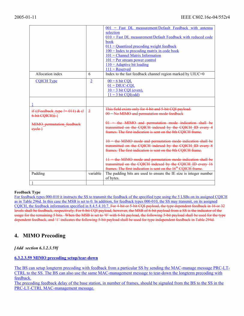
Allocation index 6 Index to the fast feedback channel region marked by UIUC=0
CQICH Type 2 00 = 6 bit CQI, 01 = DIUC-CQI, 10 = 3 bit CQI (even), 11 = 3 bit CQI(odd)
}
if ((Feedback_type != 011) & (! 6-bit CQICH)) {
MIMO_permutation_feedback cycle }
2 This field exists only for 4-bit and 5-bit CQI payload. 00 = No MIMO and permutation mode feedback 01 = the MIMO and permutation mode indication shall be transmitted on the CQICH indexed by the CQICH_ID every 4 frames. The first indication is sent on the 8th CQICH frame. 10 = the MIMO mode and permutation mode indication shall be transmitted on the CQICH indexed by the CQICH_ID every 8 frames. The first indication is sent on the 8th CQICH frame. 11 = the MIMO mode and permutation mode indication shall be transmitted on the CQICH indexed by the CQICH_ID every 16 frames. The first indication is sent on the 16th CQICH frame.
Padding variable The padding bits are used to ensure the IE size is integer number of bytes.
} Feedback Type For feedback types 000-010 it instructs the SS to transmit the feedback of the specified type using the 5 LSBs on its assigned CQICH as in Table 296d. In this case the MSB is set to 0. In addition, for feedback types 000-010, the SS may transmit, on its assigned CQICH, the feedback information specified in 8.4.5.4.10.7. For 4-bit or 5-bit CQI payload, the type dependent feedback in 16 or 32 levels shall be feedback, respectively. For 6-bit CQI payload, however, the MSB of 6-bit payload from a SS is the indicator of the usage for the remaining 5 bits. When the MSB is set to ‘0’ with 6-bit payload, the following 5-bit payload shall be used for the type dependent feedback, and ‘1’ indicates the following 5-bit payload shall be used for type independent feedback in Table 294d.
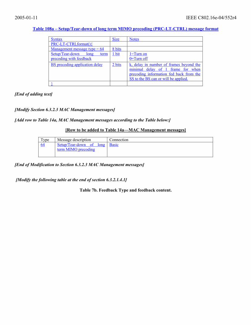
4. MIMO Precoding [Add section 6.3.2.3.59] 6.3.2.3.59 MIMO precoding setup/tear-down The BS can setup longterm precoding with feedback from a particular SS by sending the MAC-manage message PRC-LT-CTRL to the SS. The BS can also use the same MAC-management message to tear-down the longterm precoding with feedback. The precoding feedback delay of the base station, in number of frames, should be signaled from the BS to the SS in the PRC-LT-CTRL MAC-management message.
2005-01-11 IEEE C802.16e-04/552r4
Table 108a – Setup/Tear-down of long term MIMO precoding (PRC-LT-CTRL) message format
Syntax Size Notes PRC-LT-CTRLformat(){ Management message type = 64 8 bits Setup/Tear-down long term precoding with feedback
1 bit 1=Turn on 0=Turn off
BS precoding application delay 2 bits k, delay in number of frames beyond the minimal delay of 1 frame for when precoding information fed back from the SS to the BS can or will be applied.
} [End of adding text] [Modify Section 6.3.2.3 MAC Management messages] [Add row to Table 14a, MAC Management messages according to the Table below:]
[Row to be added to Table 14a—MAC Management messages]
Type Message description Connection 64 Setup/Tear-down of long
term MIMO precoding Basic
[End of Modification to Section 6.3.2.3 MAC Management messages] [Modify the following table at the end of section 6.3.2.1.4.1]
Table 7b. Feedback Type and feedback content.

2005-01-11 IEEE C802.16e-04/552r4
[End of “Modify the following table at the end of section 6.3.2.1.4.1”] [Modify the following section as indicated] 8.4.8.3.6 MIMO Precoding The space time coding output can be weighted by a matrix before mapping onto transmit antennas:
z Wx= , where x is a 1tM × vector with the output from the space-time coding (per-subcarrier), tM is the number of antennasstreams at the output of the space-time coding scheme. The matrix W is an t tN M× weighting matrix where the quantity tN is the number of actual transmit antennas. The vector z contains the signals after weighting for the different actual antennas. The labeling of the elements in the weighting matrix W is performed in accordance with the example of W given below for the case of 4 actual antennas and 2 space-time coding output antennasstreams:
=
4241
3231
2221
1211
wwwwwwww
W
Short term closed loop precoding: When Mt=1, then single stream precoding or beamforming shall be applied with the vector W of dimension 1×tN . The
transmission scheme before the precoder is the regular single antenna transmission. When Mt=2, 3 or 4, then the two,
Feedback Type
Feedback contents Description
0b0000 Set as described in table 296d. MIMO mode and permutation. Feedback 0b0001 DL average CQI (5bits) 5 bits CQI feedback 0b0010 Number of index, L (2 bits) + L
occurrences of Antenna index (2 bits) + MIMO coefficients (5 bits, 8.4.5.4.10.6)
MIMO coefficients feedback
0b0011 Preferred-DIUC (4 bits) Preferred DL channel DIUC feedback 0b0100 UL-TX-Power (7 bits) (see table 7a) UL transmission power 0b0101 Preferred DIUC(4 bits) + UL-TX-Power(7
bits) + UL-headroom (6 bits) (see Table 7a) PHY channel feedback
0b0110 Number of bands, N (2 bits) + N occurrences of ‘band index (6 bits) + CQI (5 bits)’
CQIs of multiple AMC bands
0b0111 Number of feedback types, O (2 bits) + O occurrences of ‘feedback type (4bits) + feedback content (variable)’
Multiple types of feedback
0b01000 Feedback of index to long term precoding matrix in code book (6 bits), rank of precoding code book (2 bits) and FEC and QAM feedback (6 bits) according to Table Z.
Long term precoding feedback
0b01001 Life span of short term precoding feedback (2 bits) according to Table Z.
The recommended number of frames the short term precoding feedback can be used for.
0b1001-0b1111 Reserved for future use
2005-01-11 IEEE C802.16e-04/552r4
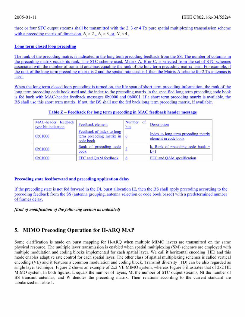
three or four STC output streams shall be transmitted with the 2, 3 or 4 Tx pure spatial multiplexing transmission scheme with a precoding matrix of dimension 2tN × , 3tN × or 4tN × .
Long term closed loop precoding The rank of the precoding matrix is indicated in the long term precoding feedback from the SS. The number of columns in the precoding matrix equals its rank. The STC scheme used, Matrix A, B or C, is selected from the set of STC schemes associated with the number of transmit antennas equaling the rank of the long term precoding matrix used. For example, if the rank of the long term precoding matrix is 2 and the spatial rate used is 1 then the Matrix A scheme for 2 Tx antennas is used. When the long term closed loop precoding is turned on, the life span of short term precoding information, the rank of the long term precoding code book used and the index to the precoding matrix in the specified long term precoding code book is fed back with MAC-header feedback messages 0b0000 and 0b0001. If a short term precoding matrix is available, the BS shall use this short term matrix. If not, the BS shall use the fed back long term precoding matrix, if available.
Table Z – Feedback for long term precoding in MAC feedback header message
MAC-header feedback type bit indication Feedback element Number of
bits Description
0b01000 Feedback of index to long term precoding matrix in code book
6 Index to long term precoding matrix element in code book
0b01000 Rank of precoding code book 2 k, Rank of precoding code book =
k+1
0b01000 FEC and QAM feedback 6 FEC and QAM specification Precoding state feedforward and precoding application delay If the precoding state is not fed forward in the DL burst allocation IE, then the BS shall apply precoding according to the precoding feedback from the SS (antenna grouping, antenna selection or code book based) with a predetermined number of frames delay. [End of modification of the following section as indicated]
5. MIMO Precoding Operation for H-ARQ MAP Some clarification is made on burst mapping for H-ARQ when multiple MIMO layers are transmitted on the same physical resource. The multiple layer transmission is enabled when spatial multiplexing (SM) schemes are employed with multiple modulation and coding blocks implemented for each spatial layer. We call it horizontal encoding (HE) and this mode enables adaptive rate control for each spatial layer. The other class of spatial multiplexing schemes is called vertical encoding (VE) and it features a common modulation and coding block. Transmit diversity (TD) can be also regarded as single layer technique. Figure 2 shows an example of 2x2 VE MIMO system, whereas Figure 3 illustrates that of 2x2 HE MIMO system. In both figures, L equals the number of layers, Mt the number of STC output streams, Nt the number of BS transmit antennas, and W denotes the precoding matrix. Their relations according to the current standard are tabularized in Table 1.

2005-01-11 IEEE C802.16e-04/552r4
Figure 2 H-ARQ Enabled Vertically Encoded 2x2 MIMO System
Figure 3 H-ARQ Enabled Horizontally Encoded 2x2 MIMO System
Layer = 1 (TD or VE only) L = 2 (HE only) L = 3 (HE only) L = 4 (HE only)
Mt=1 2 3 4 Mt=2 3 4 Mt=3 4 Mt=4
A (TD) A (TD)1 A (TD) 1
B (VE) 1 B (VE)1 B (HE)1 B (HE)1 AAS
C (VE) C (VE) C (VE) C (HE) C (HE) C (HE)
Table 1 Clarification on Layer, Mt and Matrix
FFTLog
LikelihoodRatios
Decoder
SubcarrierDemapping
ST Decoder
Modulation Sub-carrier
mapping
Sub-carrier
mapping
IFFT
IFFT
BS
SS
FECDataCRC
Nep
FFT SubcarrierDemapping
CRCcheck
ModulationFECDataCRC
STCEncoderMatrix(B, C)
Precodingmatrix
W
MtL Nt
LogLikelihood
Ratios
Decoder
CRCcheck
LNr
FFT
LogLikelihood
Ratios
Decoder
SubcarrierDemapping
ST Decoder
Modulation
STCEncoderMatrix
(A, B, C)
Sub-carrier
mapping
Sub-carrier
mapping
IFFT
IFFT
BS
SS
FECDataCRC
Nep
FFT SubcarrierDemapping
CRCcheck
Precodingmatrix
W
Mt
L=1
Nt
NrL=1

2005-01-11 IEEE C802.16e-04/552r4
In both Figure 1 and Figure 2, when there is no precoding matrix at Tx, Mt becomes the number of transmit antennas. In Table 1, the existing open-loop matrices (A, B, or C) are noted and the superscript 1 indicates the applicability of the antenna grouping technique. [Replace the following table in Section 6.3.2.3.43.6.7 as follows] 6.3.2.3.43.6.7 MIMO Compact DL MAP IE format
Table 99a—MIMO Compact DL-MAP IE format
Syntax Size (bits)
Notes
MIMO_Compact_DL-MAP_IE() {
Compact DL-MAP Type 3 Type = 7
DL-MAP Sub-type 5 MIMO = 0x01
Length 4 Length of the IE in Bytes MIMO_Type 2 Type of MIMO Mode
00 = Open-loop 01 = Antenna Grouping 10 = Antenna Selection 11 = Closed-loop code book based precoding
Num_layer 2 Number of multiple coding/modulation layers 00 – 1 layer 01 – 2 layers 10 – 3 layers 11 – 4 layers
Mode_Change 1 Indicates Change of MIMO Mode 0 = No change from previous allocation 1 = Change of MIMO Mode
If (Mode_Change) {
Matrix Indicator 2 Indicates open-loop matrix (See 8.4.8.3) 00 = Matrix A (Transmit Diversity) 01 = Matrix B (Hybrid scheme. Applicable only for 3 and 4 antennas) 10 = Matrix C (Pure Spatial Multiplexing) 11 = Reserved
Feedforward_precoding_state 1 0 – Don’t feed forward the precoding state. The precoding feedback from SS is applied by the BS after the precoding application delay. 1 – Feed forward the precoding state. The BS can apply arbitarty precoding.
If (Feedfoward_precoding_state){
Mt 2 Indicates number of STC output streams 00 = 1 stream 01 = 2 streams 10 = 3 streams 11 = 4 streams
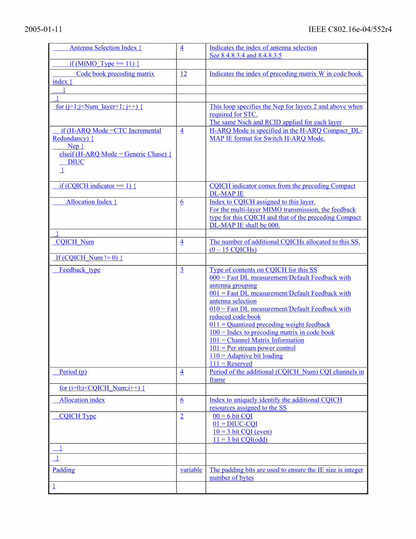
if (MIMO_Type == 01) { Antenna Grouping Index } 4 Indicates the index of antenna grouping
See 8.4.8.3.4 and 8.4.8.3.5 if (MIMO_Type == 10) {
2005-01-11 IEEE C802.16e-04/552r4
Antenna Selection Index } 4 Indicates the index of antenna selection See 8.4.8.3.4 and 8.4.8.3.5
if (MIMO_Type == 11) { Code book precoding matrix index }
12 Indicates the index of precoding matrix W in code book.
} } for (j=1;j<Num_layer+1; j++) { This loop specifies the Nep for layers 2 and above when
required for STC. The same Nsch and RCID applied for each layer
if (H-ARQ Mode =CTC Incremental Redundancy) { Nep }
elseif (H-ARQ Mode = Generic Chase) { DIUC }
4 H-ARQ Mode is specified in the H-ARQ Compact_DL-MAP IE format for Switch H-ARQ Mode.
if (CQICH indicator == 1) { CQICH indicator comes from the preceding Compact DL-MAP IE
Allocation Index } 6 Index to CQICH assigned to this layer. For the multi-layer MIMO transmission, the feedback type for this CQICH and that of the preceding Compact DL-MAP IE shall be 000.
} CQICH_Num 4 The number of additional CQICHs allocated to this SS.
(0 – 15 CQICHs) If (CQICH_Num != 0) {
Feedback_type 3 Type of contents on CQICH for this SS 000 = Fast DL measurement/Default Feedback with antenna grouping 001 = Fast DL measurement/Default Feedback with antenna selection 010 = Fast DL measurement/Default Feedback with reduced code book 011 = Quantized precoding weight feedback 100 = Index to precoding matrix in code book 101 = Channel Matrix Information 101 = Per stream power control 110 = Adaptive bit loading 111 = Reserved
Period (p) 4 Period of the additional (CQICH_Num) CQI channels in frame
for (i=0;i<CQICH_Num;i++) {
Allocation index 6 Index to uniquely identify the additional CQICH resources assigned to the SS
CQICH Type 2 00 = 6 bit CQI 01 = DIUC-CQI 10 = 3 bit CQI (even) 11 = 3 bit CQI(odd)
} }
Padding variable The padding bits are used to ensure the IE size is integer number of bytes
}
2005-01-11 IEEE C802.16e-04/552r4
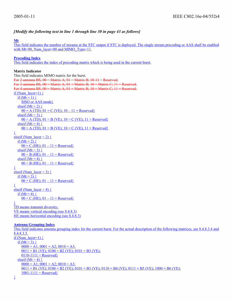
[Modify the following text in line 1 through line 30 in page 43 as follows] Mt This field indicates the number of streams at the STC output if STC is deployed. The single stream precoding or AAS shall be enabled with Mt=00, Num_layer=00 and MIMO_Type=11. Precoding Index This field indicates the index of precoding matrix which is being used in the current burst. Matrix Indicator This field indicates MIMO matrix for the burst. For 2-antenna BS, 00 = Matrix A; 01 = Matrix B; 10-11 = Reserved. For 3-antenna BS, 00 = Matrix A; 01 = Matrix B; 10 = Matrix C; 11 = Reserved. For 4-antenna BS, 00 = Matrix A; 01 = Matrix B; 10 = Matrix C; 11 = Reserved. if (Num_layer=1) {
if (Mt = 1) { SISO or AAS mode}
elseif (Mt = 2) { 00 = A (TD); 01 = C (VE); 10 – 11 = Reserved}
elseif (Mt = 3) { 00 = A (TD); 01 = B (VE); 10 = C (VE); 11 = Reserved}
elseif (Mt = 4) { 00 = A (TD); 01 = B (VE); 10 = C (VE); 11 = Reserved}
} elseif (Num_layer = 2) {
if (Mt = 2) { 00 = C (HE); 01 – 11 = Reserved}
elseif (Mt = 3) { 00 = B (HE); 01 – 11 = Reserved}
elseif (Mt = 4) { 00 = B (HE); 01 – 11 = Reserved}
} elseif (Num_layer = 3) {
if (Mt = 3) { 00 = C (HE); 01 – 11 = Reserved}
} elseif (Num_layer = 4) {
if (Mt = 4) { 00 = C (HE); 01 – 11 = Reserved}
} TD means transmit diversity; VE means vertical encoding (see 8.4.8.3) HE means horizontal encoding (see 8.4.8.3) Antenna Grouping Index This field indicates antenna grouping index for the current burst. For the actual description of the following matrices, see 8.4.8.3.4 and 8.4.8.3.5. if (Num_layer=1) {
if (Mt = 3) { 0000 = A1; 0001 = A2; 0010 = A3; 0011 = B1 (VE); 0100 = B2 (VE); 0101 = B3 (VE); 0110-1111 = Reserved}
elseif (Mt = 4) { 0000 = A1; 0001 = A2; 0010 = A3; 0011 = B1 (VE); 0100 = B2 (VE); 0101 = B3 (VE); 0110 = B4 (VE); 0111 = B5 (VE); 1000 = B6 (VE); 1001-1111 = Reserved}
}
2005-01-11 IEEE C802.16e-04/552r4
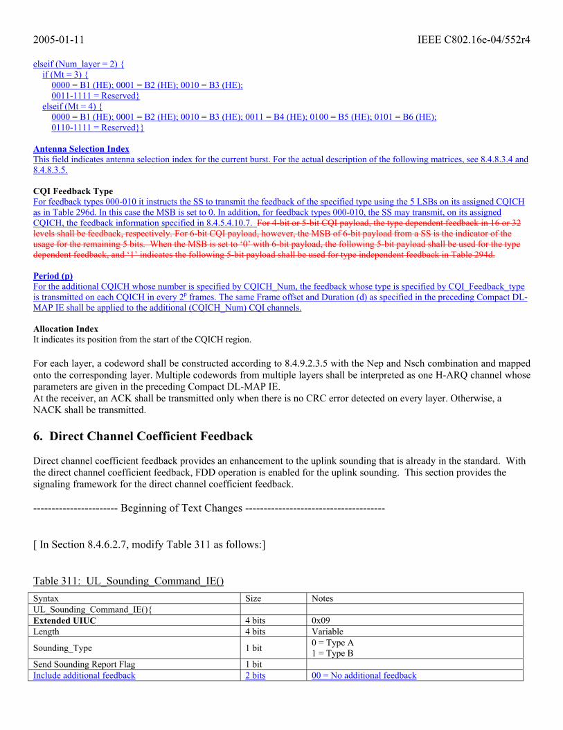
elseif (Num_layer = 2) { if (Mt = 3) {
0000 = B1 (HE); 0001 = B2 (HE); 0010 = B3 (HE); 0011-1111 = Reserved}
elseif (Mt = 4) { 0000 = B1 (HE); 0001 = B2 (HE); 0010 = B3 (HE); 0011 = B4 (HE); 0100 = B5 (HE); 0101 = B6 (HE); 0110-1111 = Reserved}}
Antenna Selection Index This field indicates antenna selection index for the current burst. For the actual description of the following matrices, see 8.4.8.3.4 and 8.4.8.3.5. CQI Feedback Type For feedback types 000-010 it instructs the SS to transmit the feedback of the specified type using the 5 LSBs on its assigned CQICH as in Table 296d. In this case the MSB is set to 0. In addition, for feedback types 000-010, the SS may transmit, on its assigned CQICH, the feedback information specified in 8.4.5.4.10.7. For 4-bit or 5-bit CQI payload, the type dependent feedback in 16 or 32 levels shall be feedback, respectively. For 6-bit CQI payload, however, the MSB of 6-bit payload from a SS is the indicator of the usage for the remaining 5 bits. When the MSB is set to ‘0’ with 6-bit payload, the following 5-bit payload shall be used for the type dependent feedback, and ‘1’ indicates the following 5-bit payload shall be used for type independent feedback in Table 294d. Period (p) For the additional CQICH whose number is specified by CQICH_Num, the feedback whose type is specified by CQI_Feedback_type is transmitted on each CQICH in every 2p frames. The same Frame offset and Duration (d) as specified in the preceding Compact DL-MAP IE shall be applied to the additional (CQICH_Num) CQI channels. Allocation Index It indicates its position from the start of the CQICH region. For each layer, a codeword shall be constructed according to 8.4.9.2.3.5 with the Nep and Nsch combination and mapped onto the corresponding layer. Multiple codewords from multiple layers shall be interpreted as one H-ARQ channel whose parameters are given in the preceding Compact DL-MAP IE. At the receiver, an ACK shall be transmitted only when there is no CRC error detected on every layer. Otherwise, a NACK shall be transmitted. 6. Direct Channel Coefficient Feedback Direct channel coefficient feedback provides an enhancement to the uplink sounding that is already in the standard. With the direct channel coefficient feedback, FDD operation is enabled for the uplink sounding. This section provides the signaling framework for the direct channel coefficient feedback. ----------------------- Beginning of Text Changes --------------------------------------
[ In Section 8.4.6.2.7, modify Table 311 as follows:]
Table 311: UL_Sounding_Command_IE() Syntax Size Notes UL_Sounding_Command_IE(){ Extended UIUC 4 bits 0x09 Length 4 bits Variable
Sounding_Type 1 bit 0 = Type A 1 = Type B
Send Sounding Report Flag 1 bit Include additional feedback 2 bits 00 = No additional feedback

2005-01-11 IEEE C802.16e-04/552r4
01 = include channel coefficients (See Section 8.4.6.2.7.3) 10 = include received pilot coefficients 11 = include feedback message
If (Sounding_Type == 0) {
Num_Sounding_symbols 3 bits Total number of sounding symbols being allocated, from 1 (“000”) to 23=8 (“111”)
Separability Type 1 bit 0: occupy all subcarriers in the assigned bands; 1: occupy decimated subcarriers
if (Separability type==0) { (using cyclic shift separability)
Max Cyclic Shift Index P 2 bits
00: P=4; 01: P=8; 10: P=16, 11: P=32
} Else { (using decimation separability)
Decimation Value D 3 bits Sound every Dth subcarrier within the sounding allocation. Decimation value D is 2 to the power of (2 plus this value), hence 4,8,… up to maximum of 64.
Decimation offset randomization 1 bit 0= no randomization of decimation offset 1= decimation offset pseudo-randomly determined
} For (i=0;i<Num_Sounding_symbols;i++){
Sounding symbol index 3 bits Symbol index within the Sounding Zone, from 1 (bits “000”) to 23=8 (bits “111”)
Number of CIDs 4 bits Number of CIDs sharing this sounding allocation For (j = 0; j<Num. of CIDs; j++) { Shorted basic CID 12 bits 12 LS bits of the MSS basic CID value Starting Frequency Band 7 bits Out of 96 bands at most (FFT size dependent) Number of frequency bands 7 bits Contiguous bands used for sounding
Power Assignment Method 2 bits
0b00 = equal power; 0b01 = reserved; 0b10 = Interference dependent. Per subcarrier power limit; 0b11 = Interference dependent. Total power limit
Power boost 1 bit 0 = no power boost 1= power boost
Multi-Antenna Flag 1 bit 0=MSS sounds first antenna only 1=MSS sounds all antennas
if (Separability type==0) {
Cyclic time shift index m 5 bits Cyclically shifts the time domain symbol by multiples (from 0 to P –1) of N/P where N=FFT size, and P=Max Cyclic Shift Index.
} Else {
Decimation Offset d 6 bits Relative starting offset position for the first sounding occupied subcarrier in the sounding allocation
}
Periodicity 2 3 bits
00=single command, not periodic, or terminate periodicity 01=repeat sounding once per frame until terminated 10= repeat instructions once per 2 frames 11= repeat instructions once per 4 frames 000 = single command, not periodic, or terminate periodicity. Otherwise, repeat sounding once per r frames, where r = 2^(n-1), where n is the decimal equivalent of the periodicity field

2005-01-11 IEEE C802.16e-04/552r4
} } } else { Permutation 2 bits 0b00 = PUSC perm.
0b01 = FUSC perm. 0b10 = Optional FUSC perm. 0b11 = Adjacent subcarrier perm.
IDcell 6 bits
Num_Sounding_symbols 3 bits
for (i=0;i<Num_Sounding_symbols;i++){
Number of CIDs 7 bits
For (j=0; j<Number of CIDs; j++) {
Shortend basic CID 12 bits 12 LS bits of the MSS basic CID value
Subchannel offset 7 bits The lowest index subchannel used for carrying the burst, starting from subchannel 0
Number of subchannels 3 bits The number subchannels with subsequent indexes, used to carry the burst.
Periodicity 2 3 bits
00=single command, not periodic, or terminate periodicity 01=repeat sounding once per frame until terminated 10= repeat instructions once per 2 frames 11= repeat instructions once per 4 frames 000 = single command, not periodic, or terminate periodicity. Otherwise, repeat sounding once per r frames, where r = 2^(n-1), where n is the decimal equivalent of the periodicity field
Power Assignment Method 2 bits
0b00 = equal power; 0b01 = reserved; 0b10 = Interference dependent. Per subcarrier power limit; 0b11 = Interference dependent. Total power limit
Power boost 1 bit 0 = no power boost 1= power boost
}
}
} Padding Variable Pad IE to octet boundary. Bits shall be set to 0 } If the field “Include Channel Coefficients” is enabled, then the UL Sounding Command IE() enables the MSS to perform the direct transmission of DL channel coefficients to the BS along with the UL sounding waveform. For the description of the direct channel coefficient encoding method, see Section 8.4.6.2.7.3.

2005-01-11 IEEE C802.16e-04/552r4
References: [1] IEEE P802.16-REVd/D5-2004 Draft IEEE Standards for local and metropolitan area networks part 16: Air interface for fixed broadband wireless access systems [2] IEEE P802.16e/D5a Air Interface for Fixed and Mobile Broadband Wireless Access Systems – Amendment for Physical and Medium Access Control Layers for Combined Fixed and Mobile Operation in Licensed Bands ,