2003 distributech conference
TRANSCRIPT

Power System Engineering, Inc. 1
Rick A. SchmidtPower System Engineering, Inc.
Web Site: www.powersystem.orgE-Mail: [email protected]
February 2, 2003, Las Vegas, Nevada
2003 DistribuTech ConferenceWireless SCADA – Beyond the Substation
2
Rick A. SchmidtCommunications ConsultantDirect Line: (608) 268-3502
Fax: (608) 222-9378Email: [email protected]
Power System Engineering, Inc.2000 Engel Street
Madison, WI 53713 Visit our Web Site at:
www.powersystem.org
Contact InformationJohn Moring
Presentation ContributorDirect Line: (760) 633-1790Email: [email protected]
John Moring ConsultingVisit our Web Site at:
www.moring.net
Copyright 2003 Power System Engineering, Inc.
Power System Engineering, Inc. 2
3
Discussion Topics/Agenda
1. 8:00 – 8:30 Introduction and Applications2. 8:30 – 8:45 Line Device Requirements3. 8:45 – 9:00 Sharing of Communications Infrastructure4. 9:00 – 10:15 Communication Technology Overview5. 10:15 –10:30 Break6. 10:30 – 11:45 Case Studies and Methodologies7. 11:45 – 12:00 Questions
4
Introduction and Applications
• SCADA Beyond the Substation =– Line Device Monitoring and or Control– The use of wireless technology as the transport– The use of the SCADA infrastructure located at the SCADA
master or other centralized energy management software packages
– Beyond the substation sites include: line device locations, including:
• Capacitor Banks• Voltage Regulators• Fault Detectors• Reclosers• Switches• Key Customer Sites
Definition and Scope of Discussion
Copyright 2003 Power System Engineering, Inc.

Power System Engineering, Inc. 3
5
Radio tower
SCADA Master
Utility Data Center
Technician Located inUtility Data Center
DistributionAsset w/
Embedded Antenna
Presentation Scope
Telco ProvidedLink
MAS Radio Provided Link
Satellite Provided Link
Spread Spectrum Radio Link
Commercial CellularProvided Link
OtherCentralizedPackages
or
Introduction and Applications
6
Introduction and Applications
• Why monitor line device sites:– Cost savings opportunities– Locate outages more quickly– Real time control through central management– Improve customer satisfaction by restoring service
more quickly– Improve employee safety– Reduce operating and maintenance costs– Remotely control distribution capacitors and switches– Potential for improved engineering by having
historical records of problem areas
Business Reasons for Introducing
Copyright 2003 Power System Engineering, Inc.

Power System Engineering, Inc. 4
7
Introduction and ApplicationsCommon Project Steps
Define the Requirements
Technology Recommendation and Conceptual Design
Technology Decision
•Detailed Design•Address Operational Issues•Detailed Cost Calculation•High-Level Roll-Out Plan
Operational Plan
Proof Of Concept Plan
Hands-on Test in Lab Environment
Roll out/Introduction
Define Project Objectives and Operational Needs
8
Define the Requirements
• Key questions to uncover:– What systems will be integrated with line device sites - e.g
SCADA, maintenance software– What type of line device assets are being considered and
quantities– What communication networks exist– What new communication programs are planned– How many sites are included in the program – by year– What is the total budget – In order to meet a business case target, what is the limit on the
one-time and recurring cost per site– Expected system life expectations– What are the “must have” functional requirements
Define the project scope and key parameters
Copyright 2003 Power System Engineering, Inc.

Power System Engineering, Inc. 5
9
Define the Requirements
• Define the communications requirements– Protocol of communication network– Protocol of line device assets connecting into communications
network– Protocol of SCADA and other systems– Network monitoring and maintenance requirements– Is one way communication acceptable, is two-way
communication a requirement– By application, how much data will be sent or received– What is an acceptable network latency interval– What is the polling sequence– What are the wireless coverage requirements
Define the Business Requirements for the Program
10
Define the Requirements
• Time frame for implementation• Ceiling costs per site• Availability of spectrum• Availability of other data communication
capabilities• Internal staffs available for implementation
or ongoing maintenance
Define Assumptions or Restrictions
Copyright 2003 Power System Engineering, Inc.

Power System Engineering, Inc. 6
11
Define the Requirements
• Protocol of end devices• Will new line devices be installed• Network interface approach • Location of end devices: pole top, pad or
underground• What intelligence is required in the IED
Define the End Device Requirements
12
Define the Requirements• Interface at end devices and communications network • Interface at SCADA Master or other management systems• Interface at applicable network hubs• Interface with any applicable third-party commercial carriers• Interface at Network “health” system
Define the end interface requirements
S C A D A C on tro lle r
R ad io to w e rIn te rconn ec t- le ased o r
sha red
R ad io to w e r
R ad ioC o n tro lle r
C a rrie rN e tw o rk
In tra ne t
R a d io tow e r
D is tribu tio nA sse t w /
e m be dde dR a d io A sse t
Copyright 2003 Power System Engineering, Inc.

Power System Engineering, Inc. 7
13
Define the Requirements
• Authentication process• Access• Encryption• Intrusion Monitoring• Redundancy• Recovery plans
Define the Security Requirements for the Program
14
Define the Requirements
• Mean time between failure• Throughput and reliability commitments• Network coverage• Acceptable latency
Other Network Performance Considerations• How to measure and track performance?• Is there a need for a service level agreement?• What is the impact for missing performance targets?
Network Performance
Copyright 2003 Power System Engineering, Inc.
Power System Engineering, Inc. 8
15
Define the Requirements
• What additional business case inputs have been uncovered?
• Any new impact on upfront and ongoing costs expected?
• Further details on labor savings, post implementation• Any new cost items need to be added or further
researched• Update management or project sponsor with new
business case items
Update the Business Case
16
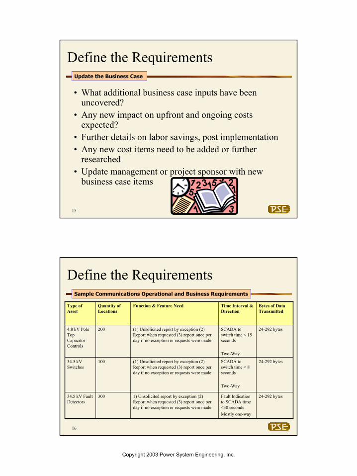
Define the Requirements
24-292 bytes
24-292 bytes
24-292 bytes
Bytes of Data Transmitted
Fault Indication to SCADA time <30 secondsMostly one-way
1) Unsolicited report by exception (2) Report when requested (3) report once per day if no exception or requests were made
30034.5 kV Fault Detectors
SCADA to switch time < 8 seconds
Two-Way
(1) Unsolicited report by exception (2) Report when requested (3) report once per day if no exception or requests were made
10034.5 kV Switches
SCADA to switch time < 15 seconds
Two-Way
(1) Unsolicited report by exception (2) Report when requested (3) report once per day if no exception or requests were made
2004.8 kV Pole Top Capacitor Controls
Time Interval & Direction
Function & Feature NeedQuantity of Locations
Type of Asset
Sample Communications Operational and Business Requirements
Copyright 2003 Power System Engineering, Inc.

Power System Engineering, Inc. 9
17
Sharing Existing Communications Infrastructure• When considering the communications alternatives for line device monitoring,
it is very appropriate to evaluate how to take advantage of any existing communications assets used for other applications or purposes.
• Examples of common communication assets owned by electrical utilities:– FCC radio license– Fiber or leased lines to substations, district offices or any locations located
throughout the service territory– Owned radio tower sites– Leased tower sites– Intellectual/knowledge– Common protocols
• Availability of third-party commercial communication services:– Cellular – Paging– Satellite
18
• Forecast future communications needs when developing plan for line device automation:– Develop a five year communications plan:
• AMR• SCADA• Load Management• Mobile Workforce Management• Data communications for district offices• Mobile voice system evolution path• Substation meter reading
Sharing Existing Communications Infrastructure
Develop a communications roadmap for future applications
Consider a shared communications strategy that facilitates the transport for multiple applications
Copyright 2003 Power System Engineering, Inc.

Power System Engineering, Inc. 10
19
Sharing Existing Communications Infrastructure• Define the communication challenges and opportunities:
– Challenges:• Long distance from line devices to Master • Hilly terrain and heavy tree foliage, buildings, traffic adds
complications• No availability of FCC radio licenses• Integration concerns
– Opportunities:• Possible excess data capacity on the substation data links used for
SCADA • Availability of commercial cellular coverage• Tower sites located throughout the service territory• Experience working with numerous wireless technologies• Others…….
20
Line Device
SCADA Server
Communications Equipment
Utility Employees
Line Device Database
Key Customer Sites
Line Device
Substation
Line Device
Line Device
Wireless CommunicationsCommunications Path
The substation could become a data concentration point
Sharing Existing Communications Infrastructure
Sharing of communications link from substation and SCADA software
Copyright 2003 Power System Engineering, Inc.

Power System Engineering, Inc. 11
Wireless SCADA – Beyond the Substation:Technologies
Las VegasFebruary 2, 2003
22
Outline
• Introduction– Overview– Wireless Characteristics– Wireline Alternatives
• Survey of Technologies
• Medium Rate Systems– Cellular Circuit Data
– Low Speed Packet Services– MAS/ VHF/UHF Private
Systems– 2.5G Cellular Packet– Point to Point Microwave
• Low Rate Systems– AMPS Control Channel– Cellular Messaging (SMS)– Paging– LEO Satellite
• High Rate Systems– GEO Satellite– Point to Point Microwave– Spread Spectrum– Free Space Optical
Created by John T. Moring
Copyright 2003 Power System Engineering, Inc.

Power System Engineering, Inc. 12
23
Introduction and ApplicationsCommon Project Steps
Business/Technical Requirements
Technology Recommendation and Conceptual Design
Technology Decision
•Detailed Design•Address Operational Issues•Detailed Cost Calculation•High-Level Roll-Out Plan
Operational Plan
Proof Of Concept Plan
Hands-on Test in Lab Environment
Roll out/Introduction
Define Project Objectives and Operational Needs
24
Wireless Landscape
10 bps
100 bps
1 kbps
10 kbps
100 kbps
1 Mbps
10 Mbps
Control Channel
Cellular SMS
Paging ReFlex
LEO Satellite
GPRS, cdma2000
MASCDPD, Motient
Cellular circuit
Microwave,Spread spectrum
VSAT
Free space optical
Medium Rate Systems
Low Rate Systems
High Rate Systems
bps: bits per second
CDPD: Cellular Digital Packet Data
MAS: Multiple Address System
VSAT: Very Small Aperture Terminal
bps: bits per second
CDPD: Cellular Digital Packet Data
MAS: Multiple Address System
VSAT: Very Small Aperture Terminal
Technologies Ranked by Throughput
Created by John T. Moring
Microwave
Copyright 2003 Power System Engineering, Inc.

Power System Engineering, Inc. 13
25
Wireless Tradeoffs
• Limitations– Performance– Range, availability– Cost– Security
• Benefits– Ease of deployment– Mobility
Why Wireless?
Created by John T. Moring
26
Wireless Performance Metrics
• Throughput– Bits per second– Messages per day
• Latency– Delays through the system– Medium– Equipment/network– Sometimes setup latency
• Range– 10's of feet to 10's of miles
• Error rate– Error correction impacts latency and throughput
Measurable aspects of the wireless technology
Created by John T. Moring
Copyright 2003 Power System Engineering, Inc.

Power System Engineering, Inc. 14
27
Other Wireless Characteristics
• Connection type– Circuit, packet, message
• Spectrum ownership– Utility, public, third-party carrier
• Service availability, coverage• Reliability• Product lifetime• Multi-vendor support• Interfaces• Equipment size, power consumption, siting,
environmental needs
Other technical aspects of the wireless technology
Created by John T. Moring
28
Connectivity Options –Private vs. Commercial
Data CenterRemote Assets
Substation or Private Tower Site
Commercial Carrier
commercial radio link
private radio link
Public or private backhaul • radio •frame relay • etc.
Public or private backhaul • Internet •frame relay • etc.
Created by John T. Moring
Copyright 2003 Power System Engineering, Inc.

Power System Engineering, Inc. 15
29
Private vs. Commercial Tradeoffs
• Private Systems – Utility owns the communication system– Available where commercial options are not feasible– Provides more control
• Potential for system tuning• Possibly higher reliability• Possibly more equipment lifecycle stability• Possibly higher security
– Possibly lower recurring costs (no usage fees)
• Commercial Systems – Utility contracts service from a third party– Economies of scale
• Usually lower equipment cost• Often greater resources
– System operation and maintenance is taken care of
Created by John T. Moring
30
Typical Remote Site Block Diagram
RTU
Antenna
Radio transceiver
Power supply
Coaxial cable
Serial cable RTU: Remote Terminal Unit
RTU: Remote Terminal Unit
Equipment components
Created by John T. Moring
Copyright 2003 Power System Engineering, Inc.

Power System Engineering, Inc. 16
31
Alternatives to Wireless
• Private media– Copper– Fiber
• Telephone company offerings– Leased line– Dial-up– Frame Relay– T-carrier– Etc.
Wireless is not the only possible solution
Created by John T. Moring
32
Low Rate Systems
• Third-Party Commercial– Generally message-based systems– Near nationwide coverage
• Including:– AMPS Control Channel– Cellular Messaging (SMS)– Paging
– LEO Satellite
• ORBCOMM• Iridium
AMPS: Advanced Mobile Phone System
LEO: Low Earth Orbit
SMS: Short Message Service
AMPS: Advanced Mobile Phone System
LEO: Low Earth Orbit
SMS: Short Message Service
Low-throughput technologies < 10 kbps
Created by John T. Moring
Copyright 2003 Power System Engineering, Inc.

Power System Engineering, Inc. 17
33
AMPS Control Channel
• "Advanced" Mobile Phone System– First generation (1G) analog– Widest coverage of all cellular systems
• There are a limited number of data bits used for signaling (e.g., called number)
• A couple companies offer service where signaling bits can be employed for user data– Celemetry, Aeris– <100 bits per message
• No circuit setup times
Leveraging high coverage of analog cellular
Created by John T. Moring
34
Cellular Messaging (SMS)
• Short Message Service (SMS)• All 2nd Generation (2G) cellular systems support SMS
– CDMA (Code Division Multiple Access)– TDMA (Time Division Multiple Access)– GSM (Global System for Mobile Communications)
• Used to deliver short text messages– Limited to ~150 characters
• Uses control channels for delivery, so voice circuit is not consumed– No circuit setup time
• Larger messages available in the future – Enhanced Messaging Service– Multimedia Messaging Service
Leveraging messaging capability of 2G digital cellular
Created by John T. Moring
Copyright 2003 Power System Engineering, Inc.

Power System Engineering, Inc. 18
35
Cellular (Analog Control Channel and SMS)
Pricing Comparison
Typical Price per Month
Service Description
Data Throughput
(Range)Analog Control Channel
1. Aeris
a. Microburst (low-volume) $6.95 3 msg/month 4 bytes per message
b. Microburst (high-volume) $46.00 400 msg/month 4 bytes per message
2. Numerex
a. Cellemetry $.10/msg Billed per message 12 bytes per message
Short Message (SMS)1. Numerex
a. Data1Source$.10/msg
Product packages are available based on volume
150 bytes per message
2. Esemde$.10/msg
Product packages are available based on volume
150 bytes per message
3. AT&T Wireless
a. Enterprise SMS Plan 1 $500.00 7,500 msg, unlimited devices
150 bytes per message
b. Enterprise SMS Plan 6 $2,500.00 1,000,000 msg, unlimited devices
150 bytes per message
Media/Service Type
36
Commercial Paging
• One-way (delivery only) vs. two way• Message based
– “Guaranteed” delivery– Store and forward
• Motorola's ReFlex technology leads two-way field– Multiple carriers, e.g., Skytel
• Message size limited (e.g., <1000 characters)
Leveraging widely deployed paging systems
Created by John T. Moring
Copyright 2003 Power System Engineering, Inc.

Power System Engineering, Inc. 19
37
Commercial PagingCommercial Paging Comparisons
Technology Product and Service Offerings
Monthly Recurring Costs for Residential
AMR or Load Management
Purposes
Useable Capacity Communication Direction
Typical Latency
900 MHz FLEX
Arch Wireless, Cannon Technologies, Metrocall, Weblink Wireless, Skytel
$2 to $4 Per Month 240 bytes
1-Way (defined from
Paging Network to receiver
30 to 90 seconds average
ReFLEX
Arch Wireless, Cannon Technologies, Metrocall, Weblink Wireless, and Skytel
$2 to $4 Per Month
500 to 2,000 bytes 2-Way
30 to 90 seconds average
Proprietary Mobitex (formally Ardis) $5 to $8 9.6 kbps to
14.4 kbps Two-Way 5 to 10 seconds
Proprietary Motient $5 to $8 9.6 kbps to 14.4 kbps Two-Way 5 to 10
secondsComments:
- ReFLEX is available in most urban areas but coverage often is not available in rural areas.- The transceiver hardware costs for telemetry paging will typically range from $75 to $100.
- FLEX is a 1-way paging technology .
38
Low Earth Orbit (LEO) Satellites
• Message-based or circuit based• Some vendors financially troubled• ORBCOMM
– Message based, high latency– Low-speed telemetry, asset tracking, messaging– ~30 LEO satellites
• Iridium– US Department of Defense and corporate customers– Voice and circuit data
• 2.4 kbps dial-up, 10 kbps Internet
• Others on the drawing board
For those hard-to-reach areas
Created by John T. Moring
Copyright 2003 Power System Engineering, Inc.

Power System Engineering, Inc. 20
39
Low Earth Orbit (LEO) Satellites
Communication Parameters Little LEO - Big LEO -
Data Throughput Range 500 bytes per message 2.4 kbps
Typical Latency on 200 Byte File 500 seconds 20 to 30
seconds
Typical Latency on 6 Byte File 500 seconds 20 to 30 seconds
Level of Coverage in US High High
Monthly Recurring Costs Per Device (Small volume) $4 to $20 $15 to $30
Monthly Recurring Costs Per Device (Large volume) $65 to $80 $65 to $80
One-Time Hardware Costs $125 to $500 $1,200 to $2,500
Leading Vendors
Orbcomm, Advanced
Cybersystems, EchoFlight
Iridium, Stratos, DBS Industries,
Vendor Comparisons
40
Low Rate Recap
• Low throughput, <10 kbps• Generally message-based systems• Third-party service operators• Near nationwide coverage• Suitable for low rate, latency tolerant, message oriented systems• Satellite available where cellular/paging networks can't reach
Fair/PoorExcellentLEO Satellite
FairGoodPaging
FairGoodSMS
FairGoodAMPS Control Channel
LatencyCoverage/ Availability
Created by John T. Moring
Copyright 2003 Power System Engineering, Inc.

Power System Engineering, Inc. 21
41
Medium Rate Systems
• 10 kbps to ~100 kbps• Circuit and packet-based systems• Third party carriers and private systems• Including
– Cellular Circuit Data– First Generation Packet Services
• CDPD• Motient• Mobitex
– Private Systems • Licensed: MAS and VHF/UHF• Unlicensed Proprietary Spread Spectrum Radio
– 2.5G Cellular Packet
CDPD: Cellular Digital Packet Data
MAS: Multiple Address System
SMR: Specialized Mobile Radio
CDPD: Cellular Digital Packet Data
MAS: Multiple Address System
SMR: Specialized Mobile Radio
Medium-throughput technologies
Created by John T. Moring
42
Cellular Circuit Data - Analog
• Dial-up modem connection over analog voice circuit
• Specialized modem protocols provide minimal performance– ETC: Enhanced Throughput Cellular– MNP: Microcom Network Protocol
• Long setup times, low throughput– ~2.4 kbps
• Not generally recommended
Possible, but not recommended
Created by John T. Moring
Copyright 2003 Power System Engineering, Inc.

Power System Engineering, Inc. 22
43
First Generation Packet Services
• Cellular Digital Packet Data (CDPD)• Mobitex• RAM/Ardis/Motient
Flexible performers
Created by John T. Moring
44
Circuit and Packet Switching
• Circuit Switching– Longer setup times– Guaranteed grade of service
• Packet Switching– Shorter setup times– More efficient network usage– "Message switching" similar
Created by John T. Moring
Copyright 2003 Power System Engineering, Inc.

Power System Engineering, Inc. 23
45
CDPD• CDPD provides true packet data transfer compatible with AMPS
– Coverage less than AMPS• Signaling rate 19.2 kbps; max user rate ~10 kbps• Digital modulation
– May use segregated channel set– May use temporarily idle voice channels
• Supported by AT&T, Verizon, others• Being phased out in favor of 2.5G packet services
CDPD: Cellular Digital Packet Data
Kbps: kilobits per second
CDPD: Cellular Digital Packet Data
Kbps: kilobits per second
Created by John T. Moring
46
RAM Mobile Data
• Similar performance to CDPD, but uses private channels
• Uses the Mobitex protocol developed by Ericsson• Operated by Cingular in USA
CDPD: Cellular Digital Packet Data
Kbps: kilobits per second
CDPD: Cellular Digital Packet Data
Kbps: kilobits per second
Created by John T. Moring
Copyright 2003 Power System Engineering, Inc.

Power System Engineering, Inc. 24
47
Ardis
• Similar in performance to CDPD, Mobitex• Uses Motorola DataTAC protocol• Operated by Motient in the USA
Created by John T. Moring
48
Licensed Radio Systems• VHF Radio
– 30 to 300 MHZ– Often used for voice communications– Data rates for older analog voice-designed VHF systems normally limited
to 1,200 bps.
• UHF Radio– 300 MHz to 3 GHZ– Most often used for voice– More “dead spots” than VHF– Utilities often use 450 MHz to 470 MHz and 800 MHz and 960 MHz for
data applications.– Normal data rates from older analog voice-designed systems around 2,400
bps.– Some vendors with data-only digital products and new modulation
technology, offer data signaling rates of 19.2 kbps.
Radio System Shared for Voice and Data
Copyright 2003 Power System Engineering, Inc.

Power System Engineering, Inc. 25
49
• MAS Radio license bands (Multiple Address System)– Point-to-multipoint – fixed sites– Data rates normally up to 9.6 kbps– Proven technology for SCADA– Per radio costs: $600 - $1,200
• VHF or UHF license bands for exclusive data use:– Separate infrastructure and license avoids congestion with voice channels– Data-only digital or IP based radio technology increases the data
throughput compared with traditional 900 MHz MAS. Data rates canexpand up to a signaling rate of 19.2 kbps (some vendors claim 33.3 kbps).
– Can be used for both fixed and mobile applications– Reduces the need to require the voice radio system to be used or designed
for data– Lower cost modems versus shared voice and data modems
Licensed Radio SystemsSeparate License and Infrastructure for Data
50
iDEN• Integrated Dispatch Enhanced Network • Special case of SMR• Nextel offers public digital cellular service in SMR bands
– Similar to TDMA cellular– Proprietary Motorola technology
• Business oriented• Unique voice feature: includes both private “walkie-talkie” mode
and PSTN interconnect• Private systems also available
– Large investment suitable only for large systems
• ~20 kbps dataPSTN: Public Switched Telephone Network
SMR: Specialized Mobile Radio
TDMA: Time Division Multiple Access
PSTN: Public Switched Telephone Network
SMR: Specialized Mobile Radio
TDMA: Time Division Multiple AccessCreated by John T. Moring
Copyright 2003 Power System Engineering, Inc.

Power System Engineering, Inc. 26
51
2.5G Cellular Packet
• Offered by GSM and CDMA cellular carriers• Shared channels• ~40 – 80 kbps• Internet-protocol based• Turned on in US in 2002• GSM offers General Packet Radio Service (GPRS)• CDMA offers 1xRTT• Available in major US markets
1x: single channel
GSM: Global System for Mobile Communications
CDMA: Code Division Multiple Access
RTT: Radio Transmission Technology
1x: single channel
GSM: Global System for Mobile Communications
CDMA: Code Division Multiple Access
RTT: Radio Transmission Technology
Will displace many older technologies
Created by John T. Moring
52
CDPD and 2.5G Cellular PacketCDPD and 2.5 G Pricing Comparison
List Price per Month
Service Description
Data Throughput (Range)
CDPD1. AT&T Wireless1
a. Wireless Data - Base Plan $8.00 + 0.0055/kbps Pay per byte 8 kbps to 10 kbps b. Wireless Data - Mobile Computing II $19.99 2MB 8 kbps to 10 kbps c. Wireless Data - Local Unlimited $54.99 unlimited 8 kbps to 10 kbps2. Verizon a. Mobile IP $25.00 unlimited 8 kbps to 10 kbps
2.5G Packet1. Verizon a. Express Network (1xRTT) $35.00 10MB 20 kbps to 120 kbps b. Express Network (1xRTT) $99.99 unlimited 20 kbps to 120 kbps2. AT&T Wireless a. Mobile Internet (GPRS) $29.99 10MB 20 kbps to 50 kbps b. Mobile Internet (GPRS) $99.99 100MB 20 kbps to 50 kbps3. Sprint a. PCS Vision $39.99 20MB 20 kbps to 120 kbps b. PCS Vision $119.99 120MB 20 kbps to 120 kbps4. Nextel a. Nextel Packet Stream $54.99 unlimited 20 kbpsNOTES:1. AT&T has formally indicated they will phase out of CDPD service while shifting their emphasis to GPRS.2. 2.5G Services are available in major metro areas.3. Prices are based on information provided by carriers in November 2002. Prices are subject to change.
Media/Service Type
Copyright 2003 Power System Engineering, Inc.

Power System Engineering, Inc. 27
53
Medium Rate Recap
• 10 kbps to ~100 kbps• Circuit and packet-based systems• Third party carriers and private systems• Trend toward 2.5G cellular• Private systems provide control, and coverage
GoodFair → Good2.5G Packet Services
GoodFairPublic SMR (i.e. Nextel)
GoodExcellentPrivate MAS/SMR
GoodFair1G Packet Services (i.e CDPD)
FairGoodCellular Circuit Data
LatencyCoverage/ Availability
Good choices for many situations
Created by John T. Moring
54
High Rate Systems
• Over 100 kbps• Including
– GEO Satellite– Point to Point Microwave– Proprietary Spread Spectrum– 802.11 b– Free Space Optical GEO: Geosynchronous Earth Orbit
Kbps: kilobits per second
GEO: Geosynchronous Earth Orbit
Kbps: kilobits per second
When you need to move serious data …
Created by John T. Moring
Copyright 2003 Power System Engineering, Inc.
Power System Engineering, Inc. 28
55
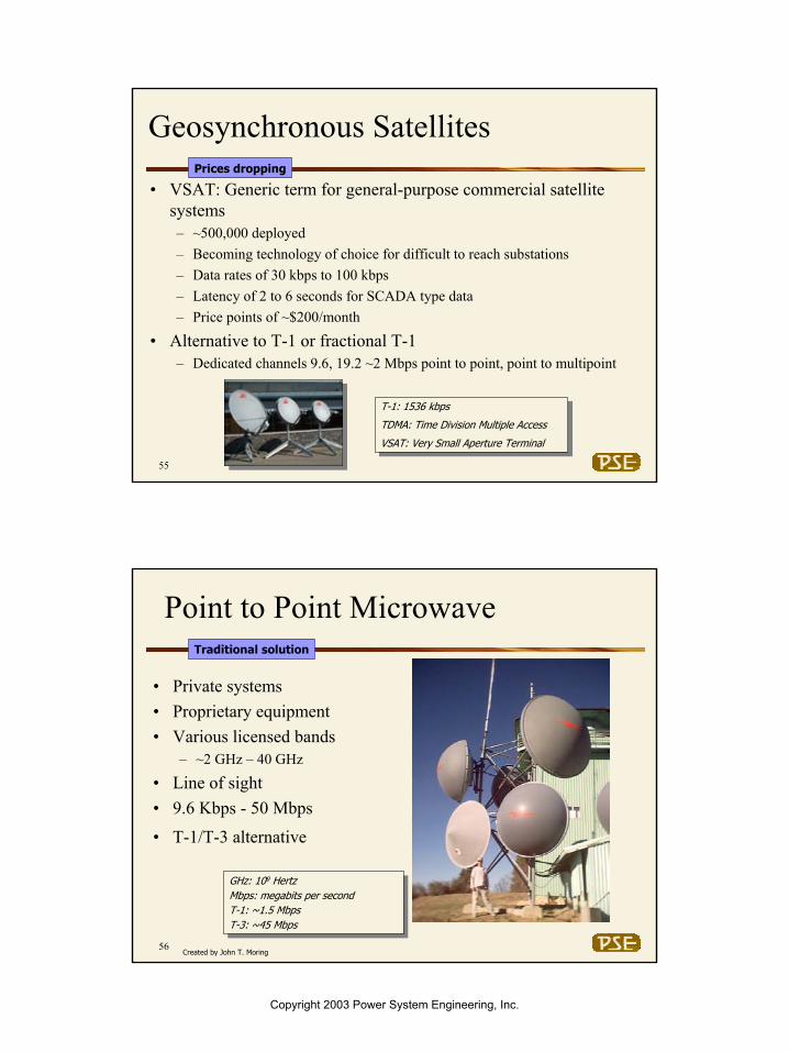
Geosynchronous Satellites
• VSAT: Generic term for general-purpose commercial satellite systems– ~500,000 deployed– Becoming technology of choice for difficult to reach substations– Data rates of 30 kbps to 100 kbps– Latency of 2 to 6 seconds for SCADA type data– Price points of ~$200/month
• Alternative to T-1 or fractional T-1– Dedicated channels 9.6, 19.2 ~2 Mbps point to point, point to multipoint
T-1: 1536 kbps
TDMA: Time Division Multiple Access
VSAT: Very Small Aperture Terminal
T-1: 1536 kbps
TDMA: Time Division Multiple Access
VSAT: Very Small Aperture Terminal
Prices dropping
56
Point to Point Microwave
• Private systems• Proprietary equipment• Various licensed bands
– ~2 GHz – 40 GHz
• Line of sight• 9.6 Kbps - 50 Mbps
• T-1/T-3 alternative
GHz: 109 HertzMbps: megabits per secondT-1: ~1.5 MbpsT-3: ~45 Mbps
GHz: 109 HertzMbps: megabits per secondT-1: ~1.5 MbpsT-3: ~45 Mbps
Traditional solution
Created by John T. Moring
Copyright 2003 Power System Engineering, Inc.

Power System Engineering, Inc. 29
57
Unlicensed Fixed Systems
• 802.11b– Some based on IEEE 802.11 standards– If IEEE 802.11b can be used with <$100 Wi-Fi modem– Common use: Wireless LAN access– Typical indoor range 150 feet, outdoor range 1,500 feet– Operates in unlicensed 2.4 GHz spectrum– ~1 to 10 Mbps– Mostly Point to Point in an office or campus environment – Double duty for mobile workforce hotspots– Easy to set up and use for private links– Subject to interference in shared bands
GHz: gigahertz
IEEE: Institute of Electrical and Electronics Engineers
GHz: gigahertz
IEEE: Institute of Electrical and Electronics Engineers
Large growth trend for Campus Environment
Created by John T. Moring
58
Unlicensed Fixed Systems
• Proprietary Spread Spectrum– Not compatible with certified IEEE 802.11b or Wi-FI – Most common at 2.4 GHz and 900 MHz – unlicensed – Common use: Point-to-point or point-to-multi-point– Typical outdoor range: 10 to 25 miles– Requires path and line of site– 900 MHz propagates better than 2.4 Ghz– Many solid vendors – Product functionality differences: i.e. repeater capability, propagation,
environment, interface, capability to add mobile, etc,– Data rates of ~9.6 kbps to 100 kbps– Some products can double duty for mobile workforce hotspots– Some risk for spectrum “overuse” interference (i.e many users sharing
spectrum)
Appropriate for many utility automation programs
Created by John T. Moring
Copyright 2003 Power System Engineering, Inc.

Power System Engineering, Inc. 30
59
High Rate Multipoint Access
• High speed radio access is available in some markets• Licensed frequencies, carrier services• Deployment slow• 10's of Mbps• LMDS
– Local Multipoint Distribution System
• MMDS– “Microwave Multipoint Distribution System” or
“Multichannel Multipoint Distribution Service”
Not widely available
Created by John T. Moring
60
Optical/Laser
• Companies are developing commercial free-space optical communications
• Point to point laser or LED links (high-speed wireless)– Like IrDA with more throughput, power, focus– Like fiber optics with no fiber– 10s Mbps – 10s Gbps typical– Range several miles– Very new with only dozens of installations
Susceptible to any blockage (e.g., fog)☺ Unlicensed; high throughput
IrDA: Infrared Data Association
LED: light emitting diode
IrDA: Infrared Data Association
LED: light emitting diode
New on the scene
Created by John T. Moring
Copyright 2003 Power System Engineering, Inc.

Power System Engineering, Inc. 31
61
High Rate Recap• Over 100 kbps• Point to point or point to multipoint• Private or unlicensed• Owned or third-party• Proprietary or open• Radio or optical
ExcellentPoor802.11b (Wi-Fi)
ExcellentFairOptical
ExcellentPoorLMDS/MMDS
ExcellentExcellentProprietary Spread Spectrum
ExcellentExcellentPoint-Point Microwave
ExcellentExcellentGEO Satellite (VSAT)
LatencyCoverage/ AvailabilityTechnology
Often overkill beyond the Substation
Created by John T. Moring
62
International Considerations
• Technology availability varies depending on local regulatory and economic environment
• Most technologies discussed here are available in North and parts of South America
• 2.5G cellular is widely available in Europe and Asia
USA is not the only utility market
Created by John T. Moring
Copyright 2003 Power System Engineering, Inc.

Power System Engineering, Inc. 32
63
In Practice
• Identify application requirements– Throughput– Latency– Etc.
• Discount any technologies unavailable in the target area• Discount any technically inappropriate technologies• Trade off remaining technologies
– Cost– Support– Etc.
• Work with vendors for trial or demo before committing
Process to Follow
Created by John T. Moring
64
Summary of Selected Technologies
FairGoodGoodPrivate MAS/SMR
GoodGoodGoodLicensed 450 MHz (separate from voice system)
FairGoodGood1G Packet Services
GoodGoodOverkillSpread Spectrum
GoodGoodOverkillPoint-Point Microwave
GoodGoodOverkillGEO Satellite (VSAT)
FairGoodGood2.5G Packet Services
FairGoodGood1G Packet Services
N/APoorGoodLEO Satellite
N/APoorGoodPaging
N/APoorGoodSMS
N/APoorGoodAMPS Control Channel
Concentrated Data (Hub)
SCADA –at
Substation
SCADA –Beyond
Substation
Match Functional Requirements with Technology
Copyright 2003 Power System Engineering, Inc.

Power System Engineering, Inc. 33
Case Studies and Methodologies
66
Case Studies and Methodologies
1,300,000 customers with about 33,000 square miles of service territory
Raleigh, NCProgress Energy Carolinas (formally (Carolina Power and Light)
7,000 customers with 6,8000 square miles of service territory
Pahrump, NVValley Electric Association
1,300,000 customers over 30,000 square miles of service territory
Albuquerque, NMPNM
1,300,000 million customers with 54,000 square miles of service territory
Madison, WIAlliant Energy
119,000 customers with over 20,000 square miles of service territory
Boyne City, MIGreat Lakes Energy
Over 480,000 customers with 4,600 square miles of service territory
Kansas City, MOKansas City Power and Light
3,800,000 residents over 468 square milesLos Angeles, CALos Angeles Department of Water and Power (LADWP)
26,000 customers with about 144 square miles of territory
Gig Harbor, WAPeninsula Light Company
Company SizeLocationUtility Name
Copyright 2003 Power System Engineering, Inc.

Power System Engineering, Inc. 34
67
Case Studies and Methodologies
•Decrease outage time•Crew safety•Improved system maintenance•An assumed safety improvement•Faster restoration of outages•Ability to monitor voltage and current all through the system•Better sectionalizing (with historical information available•Feeders can be open/closed and substations can be taken off-line remotely
Business Reasons for Introduction
•Reclosers: 58 sites•Motor Operators: 29 sites•SCADA mates: 15 sites•Switches: 1•Regulator controls (soon to be added): 27 sites
What line device assets are being monitored and or controlled?
•Having adequate RF coverage caused by•Hilly terrain
What are the biggest challenges of the program?
Peninsula Light Company
68
Case Studies and Methodologies
•With the combination of the Alligator 900 MHz licensed radio andUtilinet unlicensed spread spectrum, the coverage challenges were met.•Both the Alligator and Utilinet radios could easily be set up as a repeater radio as a means to “hop” around a barrier.•The infrastructure costs of the package (IEDs and radio) met the target cost
Key requirements that the solution met
•In place for over 4 years. Will be expanding to additional sites in 2003.•Very happy with the results
Status of the program
•Most sites utilize 900 MHz licensed MAS with Alligator Communications •Some site utilize Utilinet spread spectrum radios
Communication solution used
•Implemented radio repeater sites as a means to route around challenging terrain•Placed Utilinet Radios at the end of the line sites with a means to route around barriers
What has been done to address the challenges?
Peninsula Light Company- Continued
Copyright 2003 Power System Engineering, Inc.

Power System Engineering, Inc. 35
69
Case Studies and Methodologies
•Having adequate RF coverage caused by buildings and other structures•Meeting the stringent communication requirements of sending 240 bytes of data within 8 seconds; this presented a limited choice of wireless options.•Addressing the maintenance needs of a eventual system with 5,000 to 10,000 sites•Addressing a 10 year targeted life of the investment
What are the biggest challenges of the program?
•Improved customer satisfaction•Reduce CADI by 10 minutes (Customer Average Interruption Index)•Reduce operating and maintenance costs•Remotely control distribution capacitors and switches•Improve information for engineering and planning•Improved employee safety
Business reasons for introduction?
•Capacitor Controllers: 2,700 sites•Switches: 240•Fault Indicators: 1,850•Outage indicators: 2,000•Other hubs and general alarming: 1,000
What line device assets are being monitored and or controlled?
Los Angeles Department of Water and Power
70
Case Studies and Methodologies
•Selected commercial cellular (packet 2.5 G ) service from two different carriers: Commercial cellular best addresses network maintenance concerns of an eventual 10,000 site network, coverage throughout LA, latency and bandwidth requirements and a 10 year life expectancy
What has been done to address the challenges?
•Commercial 2.5 G cellular services of Sprint – Sprint PCS Vision•Commercial 2.5 G cellular services of Verizon – Verizon Express Network (1xRTT)By having two Cellular carrier’s using the same cellular technology (CDMA) the modem located in the IED is capable of using either carrier.
Communication Solution Used
•Being implemented in conjunction of new SCADA system and substation RTU rollout•Technology selected and contracts established•Interfaces being built•Pilot planned for 2003
Status of the program
•Excellent coverage is expected – 98% of the sites are expected•Meets Life cycle costs targets •Sufficient bandwidth and latency is expected – 40-80 kbps with less than 2 seconds latency•Will reach the 10 year life target – Historical perspective•Can be built-out and implemented in phases – No wireless infrastructure costs
Key requirements that the solution met
Los Angeles Department of Water and Power - Continued
Copyright 2003 Power System Engineering, Inc.

Power System Engineering, Inc. 36
71
Case Studies and Methodologies
•To route around barriers, a radio with flexible repeater capability is required. Only a few radio vendors offer strong repeater capability•Training of technicians has been very challenging
What are the biggest challenges of the program?
•In the wireless vendor selection process, strong repeater capability was prioritized within the decision making process• Numerous training programs are now offered for technicians
What has been done to address the challenges?
•To review operational history, the existing SCADA system is integrated with the line device program and the use of Energyline’s WinMon software
Network management health tools
•Better asset utilization with improved VAR management •More timely access to information•Ability to make better engineering related decisions driven by the use of actual historical data.
Business Reasons for Introduction
•Capacitor Controllers:350 sites•Switches: 55•In 2003, approximately 35 more capacitor control and about 10 switches will be added
What line device assets are being monitored and or controlled?
Alliant Energy
72
Case Studies and Methodologies
•Has been operational in some sites for over three years and has been in a gradual roll-out phase for over three years•Additional sites will be added in 2003•From an operational and cost standpoint, very pleased with results
Status of the program
•Best addressed the high priority of repeater capability•Cost effective•Easy to manage from a network “health” standpoint
Key requirements that the solution met
•Both UtiliNet 900 MHz spread spectrum and Locus Radio 2.4 GHz spread spectrum•MAS radio for transmission switches
Communication solution used
Alliant Energy - Continued
Copyright 2003 Power System Engineering, Inc.

Power System Engineering, Inc. 37
73
Case Studies and Methodologies
• Need for secure two-way communications•Broad geographic coverage•Sufficient bandwidth•Low cost data charge•Ease of maintenance•Supports multiple protocols
What are the biggest challenges of the program?
•Ability to adjust capacitor controllers in “real-time” based on the specific situation. Prior to automation, outside temperature was the driving factor of switching •Ability to make better engineering-related decisions driven by the use of actual historical data•Reduce outage management costs•Develop better VAr regulation (install fewer capacitor banks)•Develop an improved outage notification
Business reasons for introduction
•Capacitor Controllers: 800 sites•(IntelliTeam) Automatic Restoration System: 4 sites•Reclosers: 3 sites•Regulators: 3 sites•Fault Indicators: Pilot in 2003
What line device assets are being monitored and or controlled?
Kansas City Power and Light
74
Case Studies and Methodologies
•To review operational history, the existing SCADA system is used as a network management tool along with comparisons of data and alarms with the line device program by the use of S&C’s EnergyLine WinMon software
Network management health tools
•SchlumbergerSema (CellNet) 900 MHz spread spectrum radio provides the solution within the metro area of Kansas City. The CellNet package also provides the Energy Line Capacitor Control IED and Wide Area Network•Telemetric and the use of the Analog Control Channel has been selected for rural areas
Communication solution used
•CellNet and Telemetric best addressed the high priority need for an outsourced packaged structure•Cost effective•Easy to manage from a network “health” standpoint
Key requirements that the solution met
•Additional system growth will take place with the Capacitor controls within the greater Kansas City area in 2003, about 20 sites per year•The Telemetric Analog Control Channel deployment will be expanded in 2003 to the rural areas of the service territory•Met and exceeded all financial and business case objectives
Status of the program
•Outsourced structure of the communications management•Selection of two different technologies based on urban or rural needs•Controlled gradual roll-out of sites
What has been done to address challenges?
Kansas City Power and Light - Continued
Copyright 2003 Power System Engineering, Inc.
Power System Engineering, Inc. 38
75
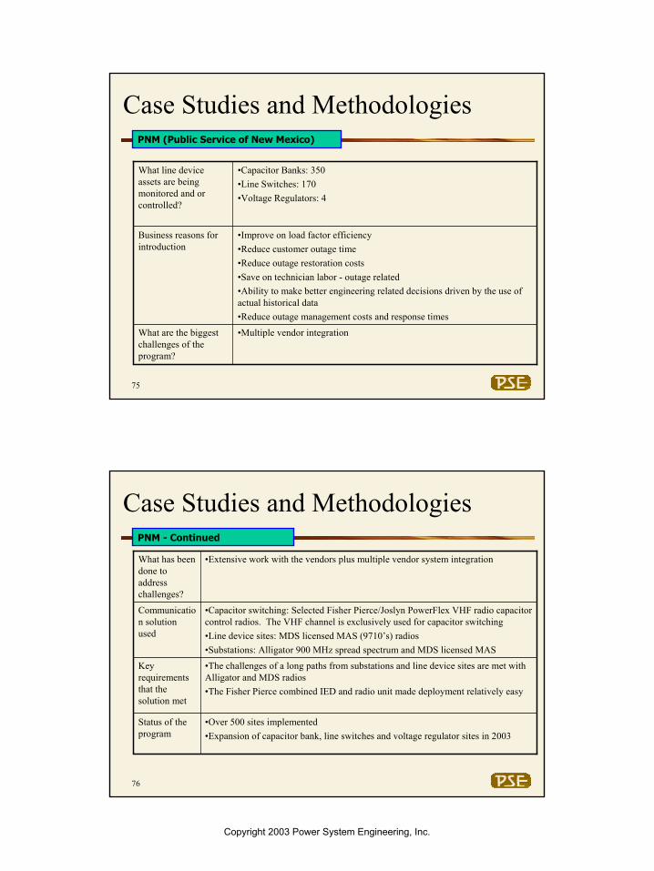
Case Studies and Methodologies
•Multiple vendor integrationWhat are the biggest challenges of the program?
•Improve on load factor efficiency•Reduce customer outage time•Reduce outage restoration costs•Save on technician labor - outage related•Ability to make better engineering related decisions driven by the use of actual historical data•Reduce outage management costs and response times
Business reasons for introduction
•Capacitor Banks: 350•Line Switches: 170•Voltage Regulators: 4
What line device assets are being monitored and or controlled?
PNM (Public Service of New Mexico)
76
Case Studies and Methodologies
•Capacitor switching: Selected Fisher Pierce/Joslyn PowerFlex VHF radio capacitor control radios. The VHF channel is exclusively used for capacitor switching•Line device sites: MDS licensed MAS (9710’s) radios•Substations: Alligator 900 MHz spread spectrum and MDS licensed MAS
Communication solution used
•The challenges of a long paths from substations and line device sites are met with Alligator and MDS radios•The Fisher Pierce combined IED and radio unit made deployment relatively easy
Key requirements that the solution met
•Over 500 sites implemented•Expansion of capacitor bank, line switches and voltage regulator sites in 2003
Status of the program
•Extensive work with the vendors plus multiple vendor system integrationWhat has been done to address challenges?
PNM - Continued
Copyright 2003 Power System Engineering, Inc.

Power System Engineering, Inc. 39
77
Case Studies and Methodologies
• Meeting a targeted investment cost per site• Convincing management that the investment is cost justified• The spread-out service territory presents limited communications options •The implementation of 1,600 sites in 18 months using the existing workforce was difficult
What are the biggest challenges of the program?
•Save on technician labor - outage related•Ability to make better engineering related decisions driven by the use of actual historical data•Reduce outage management costs (Find problems sooner)•Address needs for mobile substation (substation on wheels for restoration and maintenance purposes)
Business reasons for introduction
•Capacitor Controllers: 1,800 sites•Mobile Substation:5 portable substations
What line device assets are being monitored and or controlled?
Progress Energy Carolinas
78
Case Studies and Methodologies
•A software package by RCCS manages and supports the VAr flow and voltage management. The RCCS software also manages the communication network “health” status
Network management health tools
•900 Flex MHz one-way paging through Cannon Technologies•An Analog Control Channel arrangement with Telemetric is also being tested at this time. This provides two-way communication and enhances the capability of the one-way sites
Communication solution used
•Excellent coverage with 100% of the sites reachable•Low ongoing costs – Approximately $2/month/site communications costs•Met business case targets for upfront and ongoing costs
Key requirements that the solution met
•Currently 1,800 capacitor control sites are in service now with the communications provided by 900 Flex Paging•A Telemetric analog control channel trial will be accelerated in 2003
Status of the program
•Presented a clear business case to management to address the cost elements of the project•For ease of implementation and for cost reasons, selected commercially available communications platform of one-way paging for capacitor control sites•Selected commercially available analog control channel for mobile substations•Testing additional capacitor control sites with analog control channel
What has been done to address challenges?
Progress Energy Carolinas - Continued
Copyright 2003 Power System Engineering, Inc.

Power System Engineering, Inc. 40
79
Case Studies and Methodologies
• Need for secure two-way communications•Broad geographic coverage – over 200 mile routes•Receiving approvals form towers and repeaters•Ease of maintenance
What are the biggest challenges of the program?
•Ability to centrally manage remote sites•Provide better information to the technician prior to visiting the site to restore service•Save on technician labor - outage related•Ability to make better engineering related decisions driven by the use of actual historical data•Reduce outage management costs•Develop a improved outage notification
Business reasons for introduction
•Reclosers: 45 What line device assets are being monitored and or controlled?
Valley Electric Association
80
Case Studies and Methodologies
•Provided by Microwave Data System Network Engineering Technologies view MS network management software.
Network management health tools
•Selected Microwave Data System Spread Spectrum 900 MHz MAS radios•Selected Microwave Data System’s licensed LEDR Microwave product suite as the WAN backbone technology •Selected a radio technology that demonstrated strong repeater capability. Determined that 900 MHz spread spectrum radios are capable of coverage over 50 miles of distance.
Communication solution used
•Implementation of a wide area network to allow as a backbone for voice and data needs •The data from recloser sites are sent via spread spectrum radio to a microwave interface point. The microwave sites are located at remote district offices (closer to the reclosers). The microwave network consists of multi-hop repeaters stretching in excess of 200 miles to allow connectivity from into the central operations center.•The WAN backbone is expected to facilitate the growth of future line device and substation sites•Determined that 900 MHz MAS and 900 MHz spread spectrum radios are capable of coverage over 50 miles of distance (MDS 9810’s and 9710’s)
What has been done to address challenges?
Valley Electric Association - Continued
Copyright 2003 Power System Engineering, Inc.

Power System Engineering, Inc. 41
81
Case Studies and Methodologies
•Capability to combine 10 hops of MDS LEDR 900 MHz Microwave together•Capability to combine 3 hops of MDS 900 MHz spread spectrum together•Met all throughput and latency requirements•The Microwave backbone provides a key resource to address the challenge of the long paths•The Microwave backbone is also shared with voice and utility enterprise applications that reside in district operation offices
Key requirements that the solution met
•Very happy with the results.•Expanding additional sites in 2003
Status of the program
Valley Electric Association - Continued
82
Case Studies and Methodologies
•Spread-out service territory•Hilly terrain with heavy foliage•Limited coverage of commercial cellular service
What are the biggest challenges of the program?
•Improve the response time to outages•Save on technician field labor•Improve member satisfaction
Business Reasons for Introduction
•Capacitor banks•Fault Detectors•Switches
What line device assets are being monitored and or controlled?
Great Lakes Energy
Copyright 2003 Power System Engineering, Inc.

Power System Engineering, Inc. 42
83
Case Studies and Methodologies
•Commercially available SNMP software packages are being considered•Proprietary network management software of spread spectrum vendors
Network management health tools
•Last mile unlicensed technology routed between line device site and the nearest substation. At the substation, line device data, substation SCADA and other applications are combined on shared link and then routed to a central mater data center•Considering spread spectrum radio (900 MHz and 2.4 GHz) as last mile technology. Leading vendors being considered are MDS and Locus
Communication solution used
•Solution addresses the challenges of the large rural service territory•Solution addresses the challenges of poor cellular coverage•Meets targeted cost points
Key requirements that the solution met
•The program is in the planning phases with a communications pilot being completed during the first quarter 2003
Status of the program
•Develop a communications plan that addresses all known future data applications•Developed synergies with other data programs
What has been done to address challenges?
Great Lakes Energy - Continued
Copyright 2003 Power System Engineering, Inc.