distributech 2015 taking interoperability to the next level
TRANSCRIPT

1DISTRIBUTECH – San Diego Convention Center – San Diego, CA, USA – February 3, 2015
Riel Station
Taking Interoperability to the Next
Level
DISTRIBUTECH 2015
San Diego Convention Center, San Diego, Ca, USA
February 3, 2015

2DISTRIBUTECH – San Diego Convention Center – San Diego, CA, USA – February 3, 2015
Project Background

3DISTRIBUTECH – San Diego Convention Center – San Diego, CA, USA – February 3, 2015
Manitoba Hydro – Fast facts
● 548,700 electric customers
● Installed based capacity of
5,685 MW mainly hydraulic
● Service Area: 650,000 km2
● Capital assets in service
exceeding $15 billion
● Exports electricity to three
wholesale markets in
Canada and the mid-
western United States

4DISTRIBUTECH – San Diego Convention Center – San Diego, CA, USA – February 3, 2015
Riel Substation
● Sectionalize 500 kV line to
Minnesota
● Sectionalize 2-230 kV
network lines
● In-service-date Oct 2014
● Future site of Bipole III
(ISD 2018)
5DISTRIBUTECH – San Diego Convention Center – San Diego, CA, USA – February 3, 2015
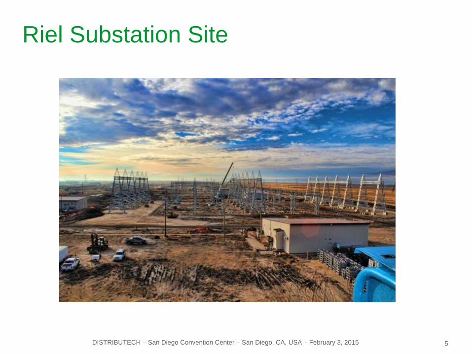
Riel Substation Site

6DISTRIBUTECH – San Diego Convention Center – San Diego, CA, USA – February 3, 2015
Technology
● Standard is A & B protection
relays from different vendors
● Utilized A & B control
systems and networks
● Utilization of IEC 61850
GOOSE messaging for
protection & control
6

7DISTRIBUTECH – San Diego Convention Center – San Diego, CA, USA – February 3, 2015
Project Overview

8DISTRIBUTECH – San Diego Convention Center – San Diego, CA, USA – February 3, 2015
Scope of Work
● Complete solution for Substation Automation (Control & Protection) – Total 77
Panels● Management, Engineering, Configuration, manufacturing, FAT, and Commissioning SAT
● Based on Schneider Electric PACiS (Protection and Control Integrated System)
& SUI (Substation User Interface) Solution.
● High IEC61850 Network Redundancy IEC61850 (Dual-homing + RSTP).
● One configuration software for all substations, with configuration of all bay
Controllers, Protective relays (reports) and HMI’s.
● NERC-CIP Compliancy.
● Capable to fulfill current and future’s requirements.● Thanks to IEC61850, today is a reality – Phase II

9DISTRIBUTECH – San Diego Convention Center – San Diego, CA, USA – February 3, 2015
Panels 500kV/230kV
500kV (Scope: detailed design, Manufacture, FAT, SAT support)
● 10 protection panels (16 Relays) + 2POW (6 IEDs), 1 Meters (3 IEDs) + 1 DR ( 2IED) + 1 Tap Controller
● 4 Control Panels (6 C264)
● 2 Server Panels (2 PACiS OI + 2 gateway+ 2 Engineering work stations)
● 2 Alarm annunciators (3 C264)
●Total= 23 panels
230kV (Scope: detailed design, Manufacture, FAT, SAT support)
● 18 protection panels (44 Relays) + 2 DR (2 IEDs), 6 POW (8 IEDs)
● 10 Control Panels (14 C264)
● 4 Server Panels (4 PACiS OI + 2 gateway + 2 engineering work stations)
● 4 Alarm annunciators (4 C264)
● Total= 44 panels

10DISTRIBUTECH – San Diego Convention Center – San Diego, CA, USA – February 3, 2015
Panels 12.47kV and IEC61850
12.47kV (Scope: detailed design, Manufacture, FAT, SAT support)
● 4 protection panels (10Relays).
● 2 Control Panels (2 C264).
● 2 Server Panels (2 PACiS OI + engineering work stations).
● 2 Alarm annunciators (2 C264)
● Total: 10 panels
IEC61850 (Scope: Goose implementation, Test philosophy, Net. topology)
● 500kV and 230kV: 50BF entirely implemented with goose.
● 12.47kV: 50BF and Bus bar protection using blocking schemes.
● Dual redundant network using dual homing and RSTP protocol to enhance network reliability

11DISTRIBUTECH – San Diego Convention Center – San Diego, CA, USA – February 3, 2015
General System Architecture
● Two different systems distributed among several buildings to:
● Supervise,
● Control,
● Protection system
● Only one supervising ring with all the information coming from different
voltage levels 12.47/230/500 kV, and the control as per voltage level and
system A or B.
● All protections and bay controllers use IEC61850 to:
● « Service report» sent directly to the control system.
● GOOSE messages between relay for protection functions.
Building
CBF1
Bay 3 & Bay 4
Busbar A1 & B1
Transformer SST1
Bay 9 & Bay 10
Busbar A2 & B2
Transformer SST2
Bank 1
Bank 1
M602F & REACTOR
D603M & Bay 1
Capacitor Bank 46kV
Bank 1
M602F & REACTOR
D603M & Bay 1
Capacitor Bank 46kV
Revenue Metering
SYSTEM « A »
230 kV
SYSTEM « B »
230 kV
SYSTEM « B »
500 kV
SYSTEM « A »
500 kV
Gateway
IEC/IEC
Building
CBF3
Building
CBF2
Bay 3 & Bay 4
Busbar A1 & B1
Transformer SST1
Bay 9 & Bay 10
Busbar A2 & B2
Transformer SST2
Bank 1
Building
CBF4
Building
CBE1
Building
CBE2
Building
SS1LBuilding
SS2L
SST1 SST2
GatewayDNP3.0
H162H162H162H162H162H162
RSG2100
RSG2100 RSG2100
RSG2100RSG2100
RSG2100
RSG2100
H162 H162
Gateway
IEC/IEC
Gateway
IEC/IECGateway
IEC/IEC
Gateway
IEC/IEC
Gateway
IEC/IEC
Gateway
IEC/IECGateway
IEC/IEC
RSG2100
HMI HMI HMI HMI HMI HMI HMICentral PC
To Industrial Data Network
(Remote access for Engineering)
GatewayDNP3.0
GatewayDNP3.0
To DNP3.0 SCADA
(Main) - 230kV
To DNP3.0 SCADA
(Secondary) - 230kVTo DNP3.0 SCADA
(Main) - 500kV
To DNP3.0 SCADA
(Secondary) - 500kV
12,47 kV
HMI

12DISTRIBUTECH – San Diego Convention Center – San Diego, CA, USA – February 3, 2015
● Time synchronization via
GPS, broadcasted using
SNTP
● System compliant with
NERC-CIP Standards
● Distributed Logics & interlocks, Control Uniqueness in a per VL basis.
● Synchro-check function integrated in Bay Controller
● Future expansion consideration (actually 40% of final project)
System Characteristics
Redundancy notion at all levels:
• Acquisition: bay controllers and protective relays
• IEC61850 network: SE Dual homing + RSTP
• Different Point-of-Control at different levels
• SCADA, redundant DNP3.0 link per voltage level

13DISTRIBUTECH – San Diego Convention Center – San Diego, CA, USA – February 3, 2015
SAS Architecture
LEGEND
C264 or
Bay controller
IED
(Protection Relay)
Ethernet Switch
Ruggedcom
RSG2100
Gateway A300
(IEC/IEC or DNP 3.0)
HMI
(Pacis OI Server & Client
Or Pacis Engineering
Workstation)
Ethernet
Switch
MiCOM H36x
GPS SNTP
(Not provided
by Areva T&D)

14DISTRIBUTECH – San Diego Convention Center – San Diego, CA, USA – February 3, 2015
• C264: Bay Controller
• RED 670 Line Protection
• SEL 487E: Transformer Diff Relay
• SEL487B: Busbar Protection Relay
• SEL421: Line Protection Relay
• GE D90+: Line Protection Relay
• SEL451: Stand Alone Protection Relay (cap
Bank)
• P991: Test Block
• P992: Multi Finger Plug
• MVAJ105: Hand and electrical reset trip relay
• C264: Bay Controller
• P546: Universal Line Protection for Breaker
and Half application, with current diff and
sub-cycle distance elements
• P643: Transformer or Reactor Protection
• P746: Busbar protection for 8 feeders
• P143: Feeder Management Relay
• P991: Test Block
• P992: Multi Finger Plug
• MVAJ105: Hand and electrical reset trip relay
Third Party products:
• TAPCON 260: voltage regulator from MR Rheinhausen
• TESLA 3000 from ERLPhase
• RSG2100/2200: Ruggedcom Switch
• ION 7650: Revenue Metering from Schneider
Primary Protection Backup Protection
Interoperability

15DISTRIBUTECH – San Diego Convention Center – San Diego, CA, USA – February 3, 2015
230 kV Protection System

16DISTRIBUTECH – San Diego Convention Center – San Diego, CA, USA – February 3, 2015
230 kV, SLD, CT & PT and Protection Zones
52-16F
52-15F
52-14F
52-13F
52-17F
52-18F
52-19F
52-20F
52-12F
52-11F
52-10F
52-09F
52-5F
52-6F
52-7F
52-8F
230kV Bus B1
230kV Bus A1
52-41F
52-24F
52-23F
52-22F
52-21FBAY 2 BAY 3
BAY 4 BAY 9 BAY 10
50:5
50:5
230kV Bus A2
M32R
M33R
M86V M87V
Bank T71
52-
121L
52-
221L
12.47kV
12.47kV
52-16F
52-15F
52-14F
52-13F
52-17F
52-18F
52-19F
52-20F
52-12F
52-11F
52-10F
52-09F
52-5F
52-6F
52-7F
52-8F
230kV Bus B1
230kV Bus A1
52-41F
52-24F
52-23F
52-22F
52-21F
11T87A/SST2
11L
21A
/L1
8F
11L
21A
/L2
2F
11L
87
A/L
15
F
11
L8
7A
/L9
F
11T87A/SST1
3
1
31
3 3
3 3
33
3 3
3 3
BAY 2 BAY 3
BAY 4 BAY 9 BAY 10
600:5
50:5
4000:5
4000:51
1B
87A
/SS
T1
V-18F V-22F
4000:5
4000:5
4000:5
4000:5
4000:5
600:5
50:5
4000:5
4000:5
4000:5
230kV Bus A2
M32R
M33R
M86V M87V
Bank T71
11
B8
7A
/SS
T2
4000:5
1
3
52-
121L
3
1
3
52-
221L
12.47kV
12.47kV
T7
1A
3
11B87A/B1F
11B87A/A1F11B87A/A2F
52-16F
52-15F
52-14F
52-13F
52-17F
52-18F
52-19F
52-20F
52-12F
52-11F
52-10F
52-09F
52-5F
52-6F
52-7F
52-8F
230kV Bus A1
52-41F
52-24F
52-23F
52-22F
52-21F
11T87A/SST2
11L
21A
/L1
8F
11L
21A
/L2
2F
11L
87A
/L1
5F
11
L8
7A
/L9
F
11T87A/SST1
3
BAY 2 BAY 3
BAY 4 BAY 9 BAY 10
600:5
50:5
11B
87A
/SS
T1
4000:5
600:5
50:5
230kV Bus A2
M32R
M33R
Bank T71
11B
87A
/SS
T2
4000:5
52-
121L
52-
221L
12.47kV
12.47kV
T7
1A
11B87A/B1F
11B87A/A1F11B87A/A2F
M87VM86V
230kV Bus B1

17DISTRIBUTECH – San Diego Convention Center – San Diego, CA, USA – February 3, 2015
Bay 2 Actual Protection Scheme (Phase 1)

18DISTRIBUTECH – San Diego Convention Center – San Diego, CA, USA – February 3, 2015
Bay 2 Protection Scheme (Expansion)

19DISTRIBUTECH – San Diego Convention Center – San Diego, CA, USA – February 3, 2015
12 kV Protection System

20DISTRIBUTECH – San Diego Convention Center – San Diego, CA, USA – February 3, 2015
Actual 12.47kV SLD/Protection System

21DISTRIBUTECH – San Diego Convention Center – San Diego, CA, USA – February 3, 2015
12.47kV Protection system specification.
● Customer requirements.
● Highly segmented BB.
● Conventional functions: 50/51, 51/51N, 50BF.
● Customer asked: What can we do to clear Bus faults without using
conventional BB protections (costly at this voltage level) or partial BB
protection?
● Basic design study.
● After studding the problem and cost restriction we chose the
implementation of BB protection with blocking scheme. The blocking is
performed by means of Goose messages allowing us a fault clearance time
of 50-55ms and an appropriate selectivity.

22DISTRIBUTECH – San Diego Convention Center – San Diego, CA, USA – February 3, 2015
BB Blocking Scheme, fed from SST1
52-106F
52-109F
52-115F
52-122F
52-121F 11F/121L
11F/106L
11F/109L
11F/115L
11F/122L
FW FW
52-215F
52-209F
52-206F
52-222F
52-221F11F/221L
11F/215L
11F/209L
11F/206L
11F/222L
FWFW
52-
8F
52-
7F
A1 B1 52-
18F
52-
17F
A2 B1
11T87A/
SST1
11T87A/
SST2
50/5
1
BL
k
BL
kB
Lk
50B
F
11B87A
/SST1
50/5
1
BLk BLk BLk
BL
k
50B
F
50B
F
50B
F
50BF50BF
50B
F
BL
k50B
F
50BF
IEDProtection Relay
50BF Goose
Blocking GooseWired Trip
Wired BF

23DISTRIBUTECH – San Diego Convention Center – San Diego, CA, USA – February 3, 2015
Testing in a IEC61850 Environment
● Customer requiremets.
● Physical blockage of goose
messages by means of test
switch.
● Indication to the Control system
that a specific relay is under
test.
● Ability to Block subscribed
messages in the relay under
test.
● Ability to block published
message at the subscriber level.
DDB #064En. Subs. Goose
DDB #065En. Pub. Goose
DDB #1888Virtual Output01
DDB #1889Virtual Output02
Allow Goose Messages from this relay to enter
the logic of the other relays
Inputs for TEST MODEUnder Test
&
DDB #205I>3 Timer Block
DDB #210IN1>3 Timer Blk
DDB #834Virtual Input 3
DDB #835Virtual Input 4
DDB #034BLK I>3 frm 106L
DDB #035BLK I>3 frm 109L
DDB #832Virtual Input 1
DDB #833Virtual Input 2
&
&
Blk I>3 from 106L
Allow Gosse from 106L
Blk I>3 from 109L
Allow Gosse from 109L
1
Bus Bar Blocking Scheme
1
2
TST(Blk I>3 from 106L)
&DDB #851Virtual Input 20
DDB #852Virtual Input 21
TST(Blk I>3 from 109L)
&
DDB #032Sub Goose Enable

24DISTRIBUTECH – San Diego Convention Center – San Diego, CA, USA – February 3, 2015
Conclusion● More than one thousand signals involved in protection schemes and system
control implemented in IEC61850 with GOOSE and reports messages for the
three voltage levels.
● Significant reduction in wiring between panels and buildings, that lowers the
risk of bad connections.
● In a traditional wired substation inter-wire faults are detected once the
functionality is not available. In IEC61850 substations FO faults are signaled
immediately avoiding potential malfunctions.
● The usage of IEC61850 allowed MH to engineer substation expansions without
inter wiring complications. This minimizes down time and potential wiring
errors. Substation upgrades may be securely tested in an emulated
environment.
● Improved system reliability due to the use of:
● System A & B protection relays.
● Protective relay with dual redundant fiber ports fitted.
● Dual Homing mechanism with 0 changeover time.
● Dual ring switches with eRSTP protocol .

25DISTRIBUTECH – San Diego Convention Center – San Diego, CA, USA – February 3, 2015
Thanks for your attention
Daniel Boucher, Utility Segment Manager
Schneider Electric, North America Operations
Claudio Rimada, Senior Engineering Manager
Schneider Electric, EAC-NAM