2001 forester service manual quick reference index ... · 4.630 kw (3,981 kcal/h, 15,797 btu/h)...
TRANSCRIPT
This service manual has been preparedto provide SUBARU service personnelwith the necessary information and datafor the correct maintenance and repair ofSUBARU vehicles.This manual includes the procedures formaintenance, disassembling, reassem-bling, inspection and adjustment of com-ponents and diagnostics for guidance ofexperienced mechanics.Please peruse and utilize this manualfully to ensure complete repair work forsatisfying our customers by keeping theirvehicle in optimum condition. Whenreplacement of parts during repair work isneeded, be sure to use SUBARU genu-ine parts.
All information, illustration and specifica-tions contained in this manual are basedon the latest product information avail-able at the time of publication approval.
FUJI HEAVY INDUSTRIES LTD.
2001 FORESTER SERVICE MANUAL QUICK REFERENCE INDEX
TRANSMISSION SECTION
G8050GE4
AUTOMATIC TRANSMISSION
ATPage
1. General Description.....................................................................................22. Automatic Transmission Fluid .....................................................................93. Differential Gear Oil ...................................................................................114. Road Test ..................................................................................................125. Stall Test....................................................................................................136. Time Lag Test............................................................................................157. Line Pressure Test ....................................................................................168. Transfer Clutch Pressure Test...................................................................189. Automatic Transmission Assembly............................................................19
10. Transmission Mounting System ................................................................2511. Extension Case Oil Seal ...........................................................................2712. Inhibitor Switch ..........................................................................................2813. Front Vehicle Speed Sensor .....................................................................3214. Rear Vehicle Speed Sensor......................................................................3615. Torque Converter Turbine Speed Sensor .................................................3716. Control Valve Body....................................................................................3817. Shift Solenoids, Duty Solenoids and ATF Temperature Sensor ...............4118. ATF Filter...................................................................................................4619. Transmission Control Module (TCM) ........................................................4820. ATF Cooler Pipe and Hose .......................................................................49
1. General Description S502001
A: SPECIFICATIONS S502001E49
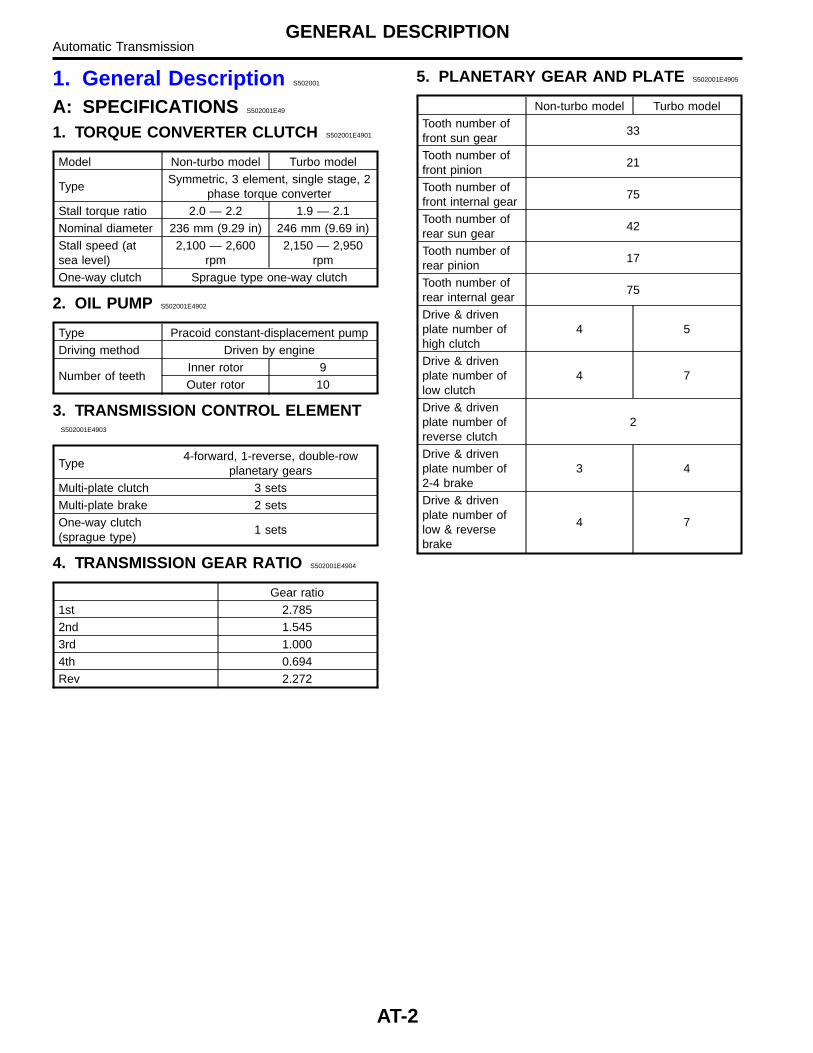
1. TORQUE CONVERTER CLUTCH S502001E4901
Model Non-turbo model Turbo model
TypeSymmetric, 3 element, single stage, 2
phase torque converterStall torque ratio 2.0 — 2.2 1.9 — 2.1Nominal diameter 236 mm (9.29 in) 246 mm (9.69 in)Stall speed (atsea level)
2,100 — 2,600rpm
2,150 — 2,950rpm
One-way clutch Sprague type one-way clutch
2. OIL PUMP S502001E4902
Type Pracoid constant-displacement pumpDriving method Driven by engine
Number of teethInner rotor 9Outer rotor 10
3. TRANSMISSION CONTROL ELEMENTS502001E4903
Type4-forward, 1-reverse, double-row
planetary gearsMulti-plate clutch 3 setsMulti-plate brake 2 setsOne-way clutch(sprague type)
1 sets
4. TRANSMISSION GEAR RATIO S502001E4904
Gear ratio1st 2.7852nd 1.5453rd 1.0004th 0.694Rev 2.272
5. PLANETARY GEAR AND PLATE S502001E4905
Non-turbo model Turbo modelTooth number offront sun gear
33
Tooth number offront pinion
21
Tooth number offront internal gear
75
Tooth number ofrear sun gear
42
Tooth number ofrear pinion
17
Tooth number ofrear internal gear
75
Drive & drivenplate number ofhigh clutch
4 5
Drive & drivenplate number oflow clutch
4 7
Drive & drivenplate number ofreverse clutch
2
Drive & drivenplate number of2-4 brake
3 4
Drive & drivenplate number oflow & reversebrake
4 7
AT-2
GENERAL DESCRIPTIONAutomatic Transmission
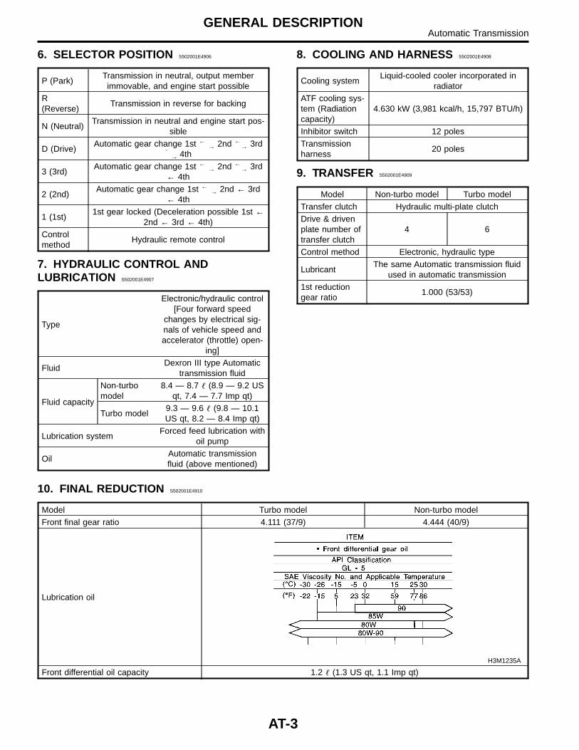
6. SELECTOR POSITION S502001E4906
P (Park)Transmission in neutral, output memberimmovable, and engine start possible
R(Reverse)
Transmission in reverse for backing
N (Neutral)Transmission in neutral and engine start pos-
sible
D (Drive)Automatic gear change 1st ←
→ 2nd ←→ 3rd
←
→ 4th
3 (3rd)Automatic gear change 1st ←
→ 2nd ←→ 3rd
← 4th
2 (2nd)Automatic gear change 1st ←
→ 2nd ← 3rd← 4th
1 (1st)1st gear locked (Deceleration possible 1st ←
2nd ← 3rd ← 4th)Controlmethod
Hydraulic remote control
7. HYDRAULIC CONTROL ANDLUBRICATION S502001E4907
Type
Electronic/hydraulic control[Four forward speed
changes by electrical sig-nals of vehicle speed andaccelerator (throttle) open-
ing]
FluidDexron III type Automatic
transmission fluid
Fluid capacity
Non-turbomodel
8.4 — 8.7 � (8.9 — 9.2 USqt, 7.4 — 7.7 Imp qt)
Turbo model9.3 — 9.6 � (9.8 — 10.1US qt, 8.2 — 8.4 Imp qt)
Lubrication systemForced feed lubrication with
oil pump
OilAutomatic transmissionfluid (above mentioned)
8. COOLING AND HARNESS S502001E4908
Cooling systemLiquid-cooled cooler incorporated in
radiatorATF cooling sys-tem (Radiationcapacity)
4.630 kW (3,981 kcal/h, 15,797 BTU/h)
Inhibitor switch 12 polesTransmissionharness
20 poles
9. TRANSFER S502001E4909
Model Non-turbo model Turbo modelTransfer clutch Hydraulic multi-plate clutchDrive & drivenplate number oftransfer clutch
4 6
Control method Electronic, hydraulic type
LubricantThe same Automatic transmission fluid
used in automatic transmission1st reductiongear ratio
1.000 (53/53)
10. FINAL REDUCTION S502001E4910
Model Turbo model Non-turbo modelFront final gear ratio 4.111 (37/9) 4.444 (40/9)
Lubrication oil
H3M1235A
Front differential oil capacity 1.2 � (1.3 US qt, 1.1 Imp qt)
AT-3
GENERAL DESCRIPTIONAutomatic Transmission
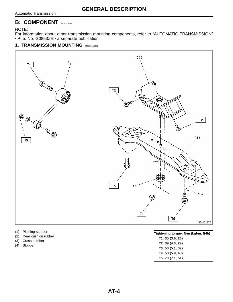
B: COMPONENT S502001A05
NOTE:For information about other transmission mounting components, refer to “AUTOMATIC TRANSMISSION”<Pub. No. G0853ZE> a separate publication.
1. TRANSMISSION MOUNTING S502001A0501
S2M0197A
(1) Pitching stopper(2) Rear cushion rubber(3) Crossmember(4) Stopper
Tightening torque: N·m (kgf-m, ft-lb)
T1: 35 (3.6, 26)T2: 39 (4.0, 29)T3: 50 (5.1, 37)T4: 58 (5.9, 43)T5: 70 (7.1, 51)
AT-4
GENERAL DESCRIPTIONAutomatic Transmission
C: CAUTION S502001A03
� Wear working clothing, including a cap, protec-tive goggles, and protective shoes during opera-tion.� Remove contamination including dirt and corro-sion before removal, installation, and disassembly.� Keep the disassembled parts in order and pro-tect them from dust or dirt.� Until the oil pan is removed, do not place withthe oil pan side facing up to prevent foreign matterfrom entering the valve body.� Before removal, installation or disassembly, besure to clarify the failure. Avoid unnecessaryremoval, installation, disassembly and replace-ment.� When disassembling the case and other lightalloy parts, use a plastic hammer to force it apart.Do not pry it apart with a screwdriver or other tool.� Be careful not to burn your hands, because eachpart on the vehicle is hot after running.� Use SUBARU genuine gear oil, grease etc. orthe equivalent. Do not mix gear oil, grease etc. with
that of another grade or from other manufacturers.� Be sure to tighten fasteners including bolts andnuts to the specified torque.� Place shop jacks or safety stands at the speci-fied points.� Apply gear oil onto sliding or revolution surfacesbefore installation.� Replace deformed or otherwise damaged snaprings with new ones.� Before installing O-rings or oil seals, apply suf-ficient amount of ATF fluid to avoid damage anddeformation.� Be careful not to incorrectly install or fail to installO-rings, snap rings and other such parts.� Before securing a part on a vise, place cushion-ing material such as wood blocks, aluminum plate,or shop cloth between the part and the vise.� Avoid damaging the mating surface of the case.� Before applying sealant, completely remove theold seal.
D: PREPARATION TOOL S502001A17
1. SPECIAL TOOLS S502001A1701
ILLUSTRATION TOOL NUMBER DESCRIPTION REMARKS
B3M1977
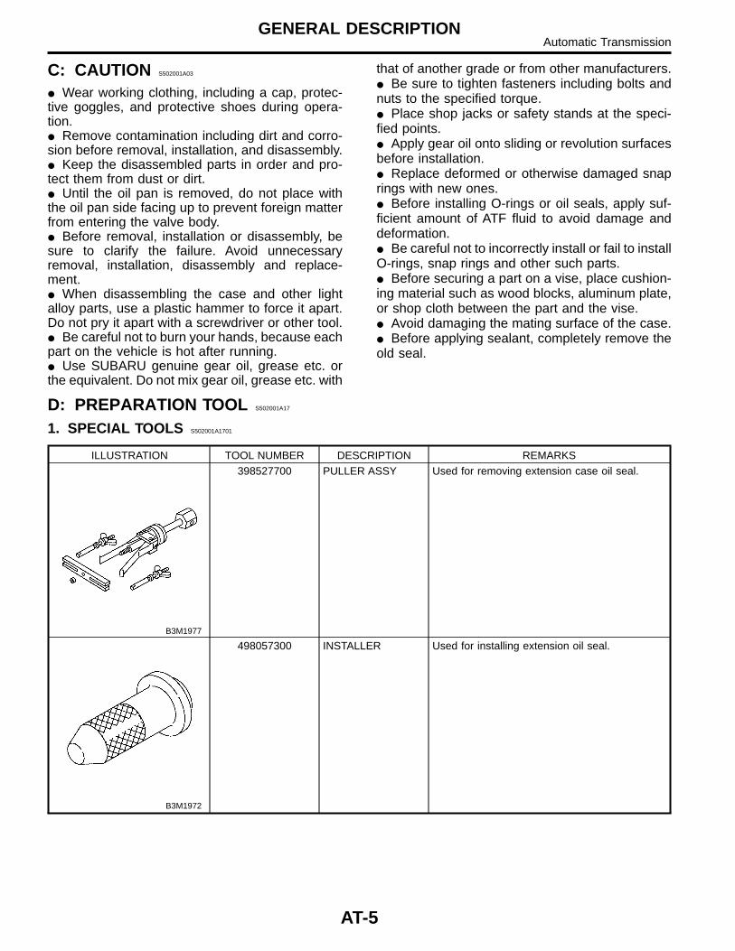
398527700 PULLER ASSY Used for removing extension case oil seal.
B3M1972
498057300 INSTALLER Used for installing extension oil seal.
AT-5
GENERAL DESCRIPTIONAutomatic Transmission
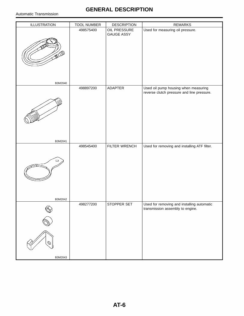
ILLUSTRATION TOOL NUMBER DESCRIPTION REMARKS
B3M2040
498575400 OIL PRESSUREGAUGE ASSY
Used for measuring oil pressure.
B3M2041
498897200 ADAPTER Used oil pump housing when measuringreverse clutch pressure and line pressure.
B3M2042
498545400 FILTER WRENCH Used for removing and installing ATF filter.
B3M2043
498277200 STOPPER SET Used for removing and installing automatictransmission assembly to engine.
AT-6
GENERAL DESCRIPTIONAutomatic Transmission
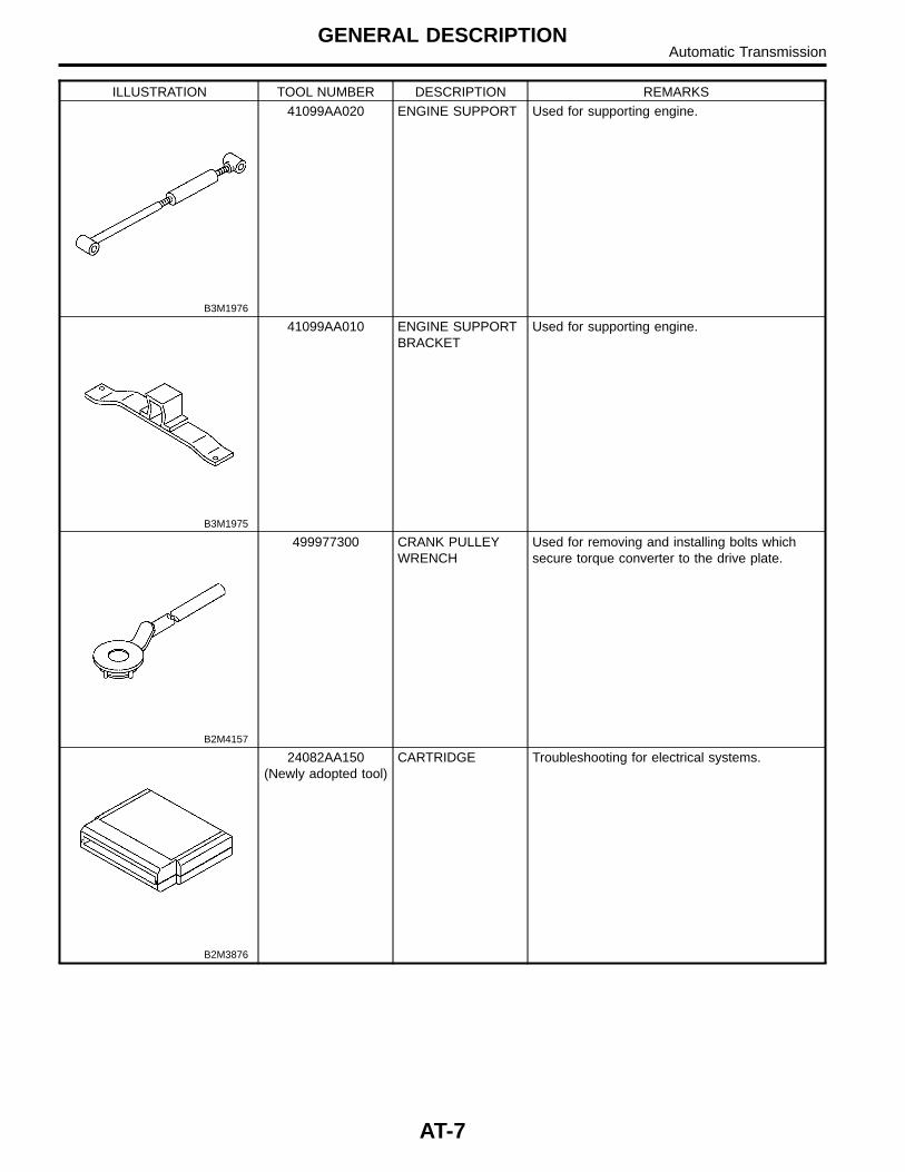
ILLUSTRATION TOOL NUMBER DESCRIPTION REMARKS
B3M1976
41099AA020 ENGINE SUPPORT Used for supporting engine.
B3M1975
41099AA010 ENGINE SUPPORTBRACKET
Used for supporting engine.
B2M4157
499977300 CRANK PULLEYWRENCH
Used for removing and installing bolts whichsecure torque converter to the drive plate.
B2M3876
24082AA150(Newly adopted tool)
CARTRIDGE Troubleshooting for electrical systems.
AT-7
GENERAL DESCRIPTIONAutomatic Transmission
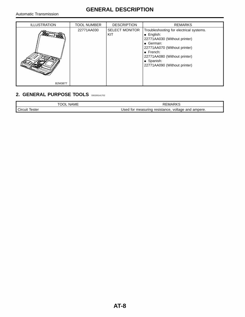
ILLUSTRATION TOOL NUMBER DESCRIPTION REMARKS
B2M3877
22771AA030 SELECT MONITORKIT
Troubleshooting for electrical systems.� English:22771AA030 (Without printer)� German:22771AA070 (Without printer)� French:22771AA080 (Without printer)� Spanish:22771AA090 (Without printer)
2. GENERAL PURPOSE TOOLS S502001A1702
TOOL NAME REMARKSCircuit Tester Used for measuring resistance, voltage and ampere.
AT-8
GENERAL DESCRIPTIONAutomatic Transmission
2. Automatic TransmissionFluid S502248
A: INSPECTION S502248A10
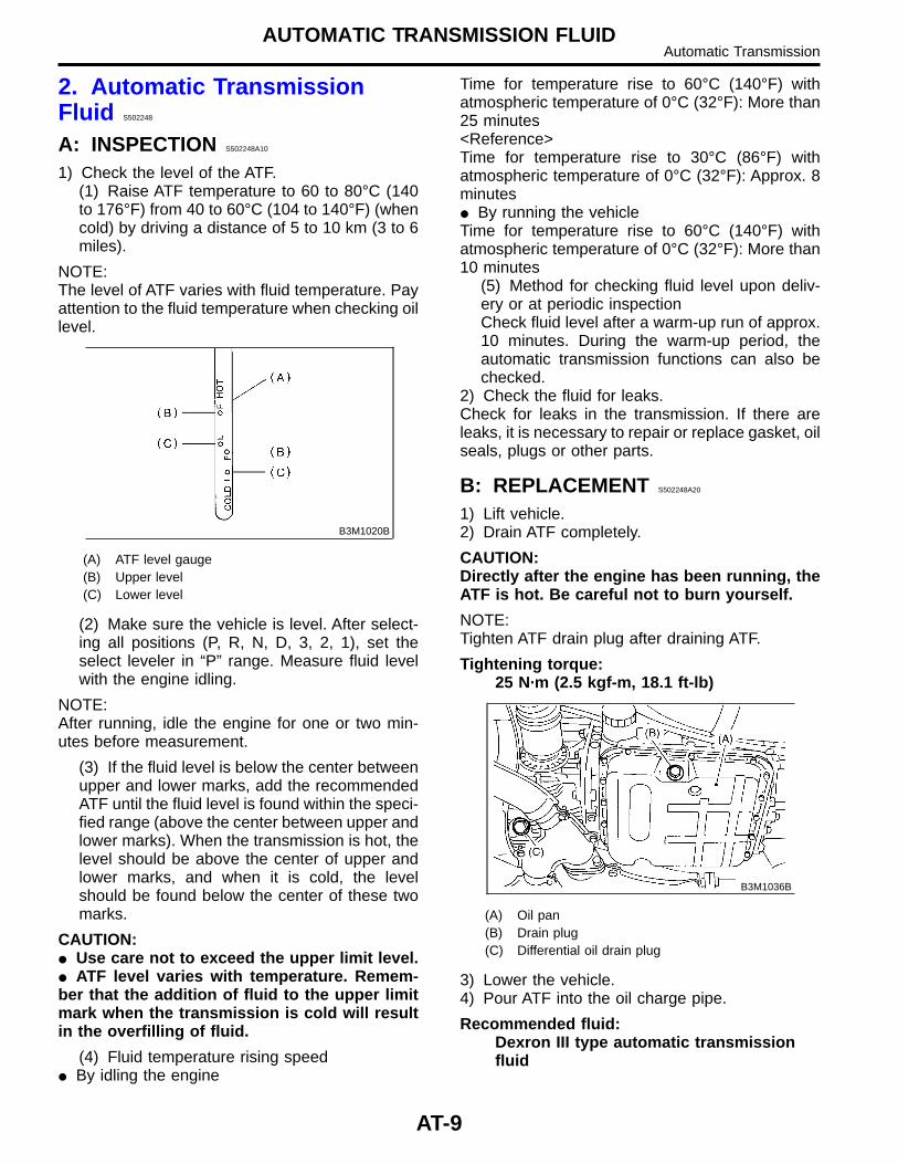
1) Check the level of the ATF.(1) Raise ATF temperature to 60 to 80°C (140to 176°F) from 40 to 60°C (104 to 140°F) (whencold) by driving a distance of 5 to 10 km (3 to 6miles).
NOTE:The level of ATF varies with fluid temperature. Payattention to the fluid temperature when checking oillevel.
B3M1020B
(A) ATF level gauge(B) Upper level(C) Lower level
(2) Make sure the vehicle is level. After select-ing all positions (P, R, N, D, 3, 2, 1), set theselect leveler in “P” range. Measure fluid levelwith the engine idling.
NOTE:After running, idle the engine for one or two min-utes before measurement.
(3) If the fluid level is below the center betweenupper and lower marks, add the recommendedATF until the fluid level is found within the speci-fied range (above the center between upper andlower marks). When the transmission is hot, thelevel should be above the center of upper andlower marks, and when it is cold, the levelshould be found below the center of these twomarks.
CAUTION:� Use care not to exceed the upper limit level.� ATF level varies with temperature. Remem-ber that the addition of fluid to the upper limitmark when the transmission is cold will resultin the overfilling of fluid.
(4) Fluid temperature rising speed� By idling the engine
Time for temperature rise to 60°C (140°F) withatmospheric temperature of 0°C (32°F): More than25 minutes<Reference>Time for temperature rise to 30°C (86°F) withatmospheric temperature of 0°C (32°F): Approx. 8minutes� By running the vehicleTime for temperature rise to 60°C (140°F) withatmospheric temperature of 0°C (32°F): More than10 minutes
(5) Method for checking fluid level upon deliv-ery or at periodic inspectionCheck fluid level after a warm-up run of approx.10 minutes. During the warm-up period, theautomatic transmission functions can also bechecked.
2) Check the fluid for leaks.Check for leaks in the transmission. If there areleaks, it is necessary to repair or replace gasket, oilseals, plugs or other parts.
B: REPLACEMENT S502248A20
1) Lift vehicle.2) Drain ATF completely.
CAUTION:Directly after the engine has been running, theATF is hot. Be careful not to burn yourself.
NOTE:Tighten ATF drain plug after draining ATF.
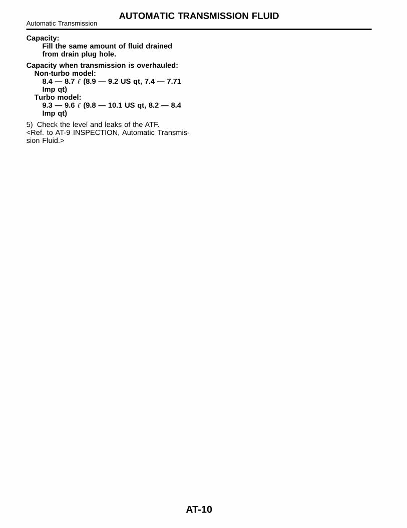
Tightening torque:25 N·m (2.5 kgf-m, 18.1 ft-lb)
B3M1036B
(A) Oil pan(B) Drain plug(C) Differential oil drain plug
3) Lower the vehicle.4) Pour ATF into the oil charge pipe.
Recommended fluid:Dexron III type automatic transmissionfluid
AT-9
AUTOMATIC TRANSMISSION FLUIDAutomatic Transmission
Capacity:Fill the same amount of fluid drainedfrom drain plug hole.
Capacity when transmission is overhauled:Non-turbo model:
8.4 — 8.7 � (8.9 — 9.2 US qt, 7.4 — 7.71Imp qt)
Turbo model:9.3 — 9.6 � (9.8 — 10.1 US qt, 8.2 — 8.4Imp qt)
5) Check the level and leaks of the ATF.<Ref. to AT-9 INSPECTION, Automatic Transmis-sion Fluid.>
AT-10
AUTOMATIC TRANSMISSION FLUIDAutomatic Transmission
3. Differential Gear Oil S502150
A: INSPECTION S502150A10
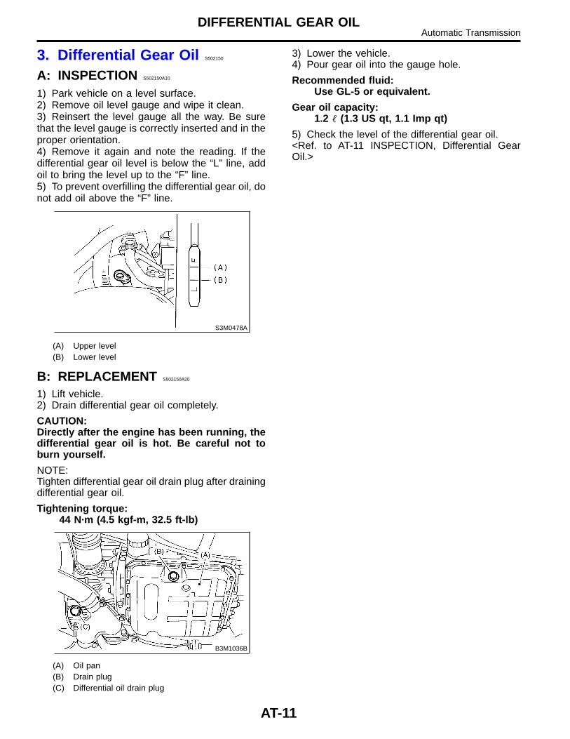
1) Park vehicle on a level surface.2) Remove oil level gauge and wipe it clean.3) Reinsert the level gauge all the way. Be surethat the level gauge is correctly inserted and in theproper orientation.4) Remove it again and note the reading. If thedifferential gear oil level is below the “L” line, addoil to bring the level up to the “F” line.5) To prevent overfilling the differential gear oil, donot add oil above the “F” line.
S3M0478A
(A) Upper level(B) Lower level
B: REPLACEMENT S502150A20
1) Lift vehicle.2) Drain differential gear oil completely.
CAUTION:Directly after the engine has been running, thedifferential gear oil is hot. Be careful not toburn yourself.
NOTE:Tighten differential gear oil drain plug after drainingdifferential gear oil.
Tightening torque:44 N·m (4.5 kgf-m, 32.5 ft-lb)
B3M1036B
(A) Oil pan(B) Drain plug(C) Differential oil drain plug
3) Lower the vehicle.4) Pour gear oil into the gauge hole.
Recommended fluid:Use GL-5 or equivalent.
Gear oil capacity:1.2 � (1.3 US qt, 1.1 Imp qt)
5) Check the level of the differential gear oil.<Ref. to AT-11 INSPECTION, Differential GearOil.>
AT-11
DIFFERENTIAL GEAR OILAutomatic Transmission
4. Road Test S502247
A: INSPECTION S502247A10
1. GENERAL PRECAUTION S502247A1001
Road tests should be conducted to properly diag-nose the condition of the automatic transmission.
CAUTION:When performing test, do not exceed postedspeed limit.
2. D RANGE SHIFT FUNCTION S502247A1002
Check shifting between 1st ⇔ 2nd ⇔ 3rd ⇔ 4thwhile driving on normal city streets.
3. D RANGE SHIFT SHOCK S502247A1003
Check the shock level when shifting up during nor-mal driving.
4. KICK-DOWN FUNCTION S502247A1004
Check kick-down for each gear. Also check thekick-down shock level.
5. ENGINE BRAKE OPERATION S502247A1005
� Check the 3rd gear engine brake when shiftingbetween D ⇔ 3rd range while driving in 4th gearof D range [50 to 60 km/h (31 to 37 MPH)].� Check the 2nd gear engine brake when shiftingbetween 3 ⇔ 2 range while driving in the 3 range3rd gear [40 to 50 km/h (25 to 31 MPH)].� Check the 1st gear engine brake when shiftingbetween 2 ⇔1 range while driving in the 2 range2nd gear [20 to 30 km/h ( 12 to 19 MPH)].
6. LOCK-UP FUNCTION S502247A1006
Check that rpm does not change sharply when theaxle pedal is lightly depressed when driving on flatroads at normal speed in the lock-up range.
7. P RANGE OPERATION S502247A1007
Stop the vehicle on an uphill grade of 5% or moreand shift to P range. Check that the vehicle doesnot move when the parking brake is released.
8. UNUSUAL SOUNDS AND VIBRATIONS502247A1008
Check for unusual sounds and vibration while driv-ing and during shifting.
9. CLIMBING CONTROL FUNCTION S502247A1009
� Check that gear remains in 3rd when going upa grade.� Check that gear remains in 3rd when applyingthe brakes while going down a grade.
10. OIL LEAKS S502247A1010
After the driving test, inspect for oil leaks.
AT-12
ROAD TESTAutomatic Transmission
5. Stall Test S502246
A: INSPECTION S502246A10
1. GENERAL INFORMATION S502246A1001
The stall test is of extreme importance in diagnos-ing the condition of the automatic transmission andthe engine. It should be conducted to measure theengine stall speeds in R and 2 ranges.Purposes of the stall test:1) To check the operation of the automatic trans-mission clutch.2) To check the operation of the torque converterclutch.3) To check engine performance.
2. TEST METHODS S502246A1002
1) Preparations before test:(1) Check that throttle valve opens fully.(2) Check that engine oil level is correct.(3) Check that coolant level is correct.(4) Check that ATF level is correct.(5) Check that differential gear oil level is cor-rect.(6) Increase ATF temperature to 50 to 80°C(122 to 176°F) by idling the engine for approxi-mately 30 minutes (with select lever set to “N”or “P”).
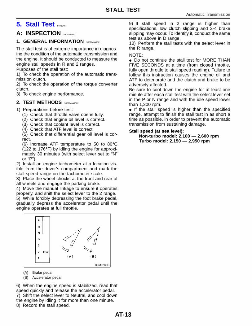
2) Install an engine tachometer at a location vis-ible from the driver’s compartment and mark thestall speed range on the tachometer scale.3) Place the wheel chocks at the front and rear ofall wheels and engage the parking brake.4) Move the manual linkage to ensure it operatesproperly, and shift the select lever to the 2 range.5) While forcibly depressing the foot brake pedal,gradually depress the accelerator pedal until theengine operates at full throttle.
B3M0286C
(A) Brake pedal(B) Accelerator pedal
6) When the engine speed is stabilized, read thatspeed quickly and release the accelerator pedal.7) Shift the select lever to Neutral, and cool downthe engine by idling it for more than one minute.8) Record the stall speed.
9) If stall speed in 2 range is higher thanspecifications, low clutch slipping and 2-4 brakeslipping may occur. To identify it, conduct the sametest as above in D range.10) Perform the stall tests with the select lever inthe R range.
NOTE:� Do not continue the stall test for MORE THANFIVE SECONDS at a time (from closed throttle,fully open throttle to stall speed reading). Failure tofollow this instruction causes the engine oil andATF to deteriorate and the clutch and brake to beadversely affected.Be sure to cool down the engine for at least oneminute after each stall test with the select lever setin the P or N range and with the idle speed lowerthan 1,200 rpm.� If the stall speed is higher than the specifiedrange, attempt to finish the stall test in as short atime as possible, in order to prevent the automatictransmission from sustaining damage.
Stall speed (at sea level):Non-turbo model: 2,100 — 2,600 rpmTurbo model: 2,150 — 2,950 rpm
AT-13
STALL TESTAutomatic Transmission
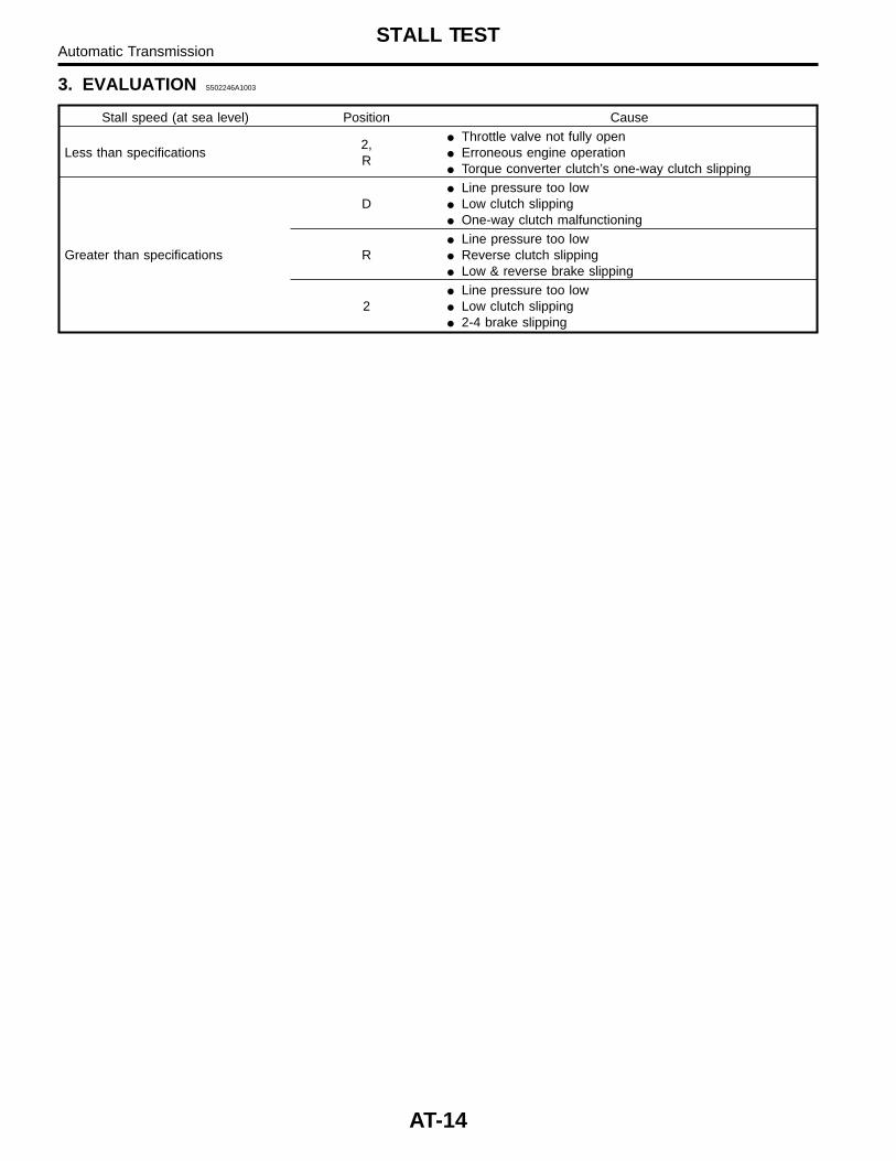
3. EVALUATION S502246A1003
Stall speed (at sea level) Position Cause
Less than specifications2,R
� Throttle valve not fully open� Erroneous engine operation� Torque converter clutch’s one-way clutch slipping
Greater than specifications
D� Line pressure too low� Low clutch slipping� One-way clutch malfunctioning
R� Line pressure too low� Reverse clutch slipping� Low & reverse brake slipping
2� Line pressure too low� Low clutch slipping� 2-4 brake slipping
AT-14
STALL TESTAutomatic Transmission
6. Time Lag Test S502245
A: INSPECTION S502245A10
1. GENERAL INFORMATION S502245A1001
If the select lever is shifted while the engine isidling, there will be a certain time elapse or lagbefore the shock can be felt. This is used forchecking the condition of the low clutch, reverseclutch, low & reverse brake and one-way clutch.
CAUTION:� Perform the test at normal operation fluidtemperature 60 to 80°C (140 to 176°F).� Be sure to allow a one minute intervalbetween tests.� Make three measurements and take the aver-age value.
2. TEST METHODS S502245A1002
1) Fully apply the parking brake.2) Start the engine.Check idling speed (A/C OFF).3) Shift the select lever from “N” to “D” range.Using a stop watch, measure the time it takes fromshifting the lever until the shock is felt.
Time lag: Less than 1.2 seconds4) In same manner, measure the time lag for “N”→ “R”.
Time lag: Less than 1.5 seconds
3. EVALUATION S502245A1003
1) If “N” → “D” time lag is longer than specified:� Line pressure too low� Low clutch worn� One-way clutch not operating properly2) If “N” → “R” time lag is longer than specified:� Line pressure too low� Reverse clutch worn� Low & reverse brake worn
AT-15
TIME LAG TESTAutomatic Transmission
7. Line Pressure Test S502244
A: MEASUREMENT S502244A14
1. GENERAL INFORMATION S502244A1401
If the clutch or the brake shows a sign of slippageor shifting sensation is not correct, the line pres-sure should be checked.� Excessive shocks during upshifting or shiftingtakes place at a higher point than under normalcircumstances, may be due to the line pressurebeing too high.� Slippage or inability to operate the vehicle may,in most cases, be due to loss of oil pressure for theoperation of the clutch, brake or control valve.1) Line pressure measurement (under no load)
CAUTION:� Before measuring line pressure, jack-up allwheels.� Maintain temperature of ATF at approxi-mately 50°C (122°F) during measurement.(ATF will reach the above temperature afteridling the engine for approximately 30 minuteswith select lever in “N” or “P”.)
2) Line pressure measurement (under heavy load)
CAUTION:� Before measuring line pressure, apply bothfoot and parking brakes with all wheelschocked (Same as for “stall” test conditions).� Measure line pressure when select lever is in“R”, “2” with engine under stall conditions.� Measure line pressure within 5 seconds aftershifting the select lever to each position. (If linepressure needs to be measured again, allowthe engine to idle and then stop. Wait for atleast one minute before measurement.)� Maintain the temperature of ATF at approxi-mately 50°C (122°F) during measurement. (ATFwill reach the above temperature after idlingthe engine for approximately 30 minutes withthe select lever in “N” or “P”.)
2. TEST METHODS S502244A1402
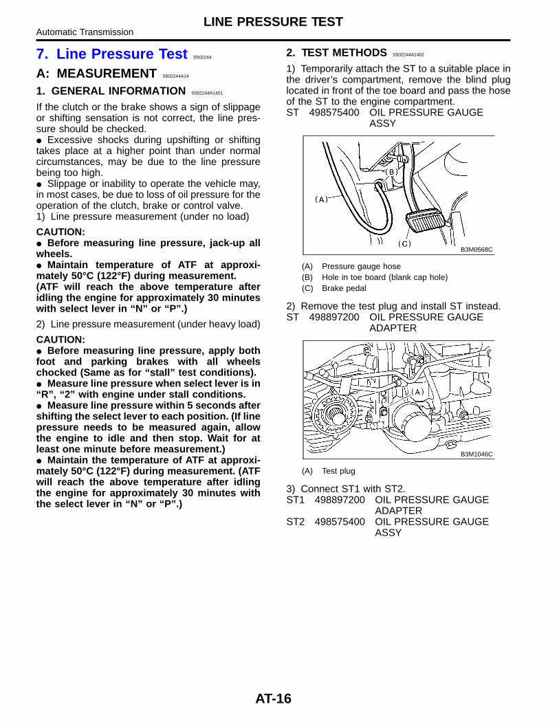
1) Temporarily attach the ST to a suitable place inthe driver’s compartment, remove the blind pluglocated in front of the toe board and pass the hoseof the ST to the engine compartment.ST 498575400 OIL PRESSURE GAUGE
ASSY
B3M0568C
(A) Pressure gauge hose(B) Hole in toe board (blank cap hole)(C) Brake pedal
2) Remove the test plug and install ST instead.ST 498897200 OIL PRESSURE GAUGE
ADAPTER
B3M1046C
(A) Test plug
3) Connect ST1 with ST2.ST1 498897200 OIL PRESSURE GAUGE
ADAPTERST2 498575400 OIL PRESSURE GAUGE
ASSY
AT-16
LINE PRESSURE TESTAutomatic Transmission
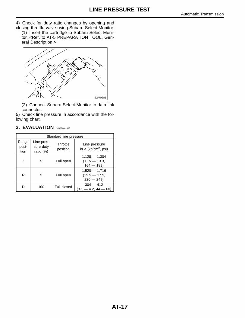
4) Check for duty ratio changes by opening andclosing throttle valve using Subaru Select Monitor.
(1) Insert the cartridge to Subaru Select Moni-tor. <Ref. to AT-5 PREPARATION TOOL, Gen-eral Description.>
S2M0286
(2) Connect Subaru Select Monitor to data linkconnector.
5) Check line pressure in accordance with the fol-lowing chart.
3. EVALUATION S502244A1403
Standard line pressure
Rangeposi-tion
Line pres-sure dutyratio (%)
Throttleposition
Line pressurekPa (kg/cm2, psi)
2 5 Full open1,128 — 1,304(11.5 — 13.3,164 — 189)
R 5 Full open1,520 — 1,716(15.5 — 17.5,220 — 249)
D 100 Full closed304 — 412
(3.1 — 4.2, 44 — 60)
AT-17
LINE PRESSURE TESTAutomatic Transmission
8. Transfer Clutch PressureTest S502159
A: INSPECTION S502159A10
1. TEST METHODS S502159A1001
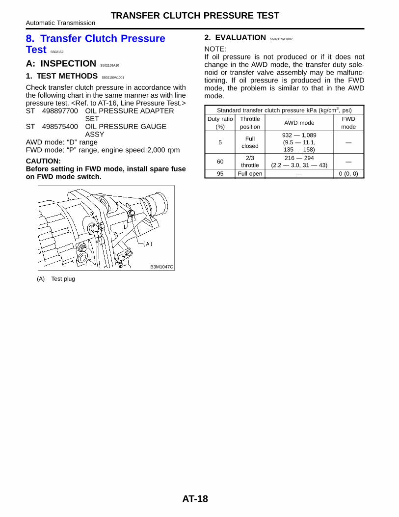
Check transfer clutch pressure in accordance withthe following chart in the same manner as with linepressure test. <Ref. to AT-16, Line Pressure Test.>ST 498897700 OIL PRESSURE ADAPTER
SETST 498575400 OIL PRESSURE GAUGE
ASSYAWD mode: “D” rangeFWD mode: “P” range, engine speed 2,000 rpm
CAUTION:Before setting in FWD mode, install spare fuseon FWD mode switch.
B3M1047C
(A) Test plug
2. EVALUATION S502159A1002
NOTE:If oil pressure is not produced or if it does notchange in the AWD mode, the transfer duty sole-noid or transfer valve assembly may be malfunc-tioning. If oil pressure is produced in the FWDmode, the problem is similar to that in the AWDmode.
Standard transfer clutch pressure kPa (kg/cm2, psi)
Duty ratio(%)
Throttleposition
AWD modeFWDmode
5Full
closed
932 — 1,089(9.5 — 11.1,135 — 158)
—
602/3
throttle216 — 294
(2.2 — 3.0, 31 — 43)—
95 Full open — 0 (0, 0)
AT-18
TRANSFER CLUTCH PRESSURE TESTAutomatic Transmission
9. Automatic TransmissionAssembly S502207
A: REMOVAL S502207A18
1) Set vehicle on a lift.2) Open front hood fully, and support with stay.3) Disconnect battery ground terminal.4) Remove air intake duct and cleaner case. (Non-turbo model) <Ref. to IN(SOHC)-8, REMOVAL, AirIntake Duct.> and <Ref. to IN(SOHC)-7,REMOVAL, Air Cleaner Case.>5) Remove air cleaner case stay. (Non-turbomodel)
S2M0901
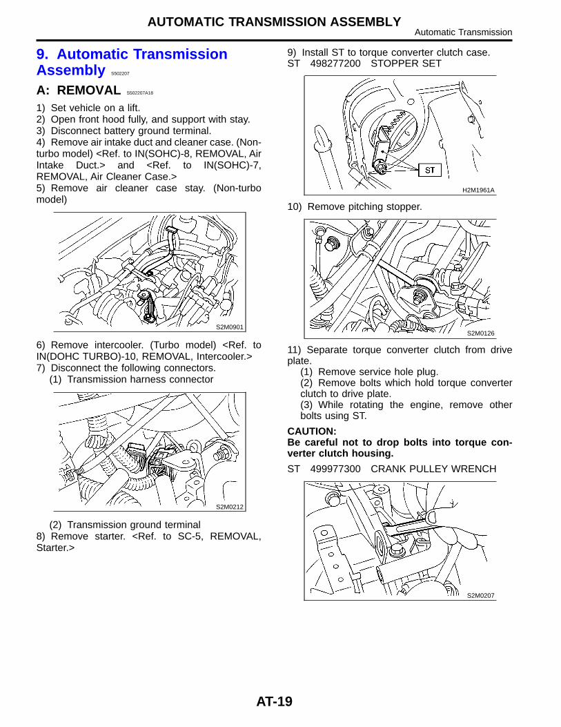
6) Remove intercooler. (Turbo model) <Ref. toIN(DOHC TURBO)-10, REMOVAL, Intercooler.>7) Disconnect the following connectors.
(1) Transmission harness connector
S2M0212
(2) Transmission ground terminal8) Remove starter. <Ref. to SC-5, REMOVAL,Starter.>
9) Install ST to torque converter clutch case.ST 498277200 STOPPER SET
H2M1961A
10) Remove pitching stopper.
S2M0126
11) Separate torque converter clutch from driveplate.
(1) Remove service hole plug.(2) Remove bolts which hold torque converterclutch to drive plate.(3) While rotating the engine, remove otherbolts using ST.
CAUTION:Be careful not to drop bolts into torque con-verter clutch housing.
ST 499977300 CRANK PULLEY WRENCH
S2M0207
AT-19
AUTOMATIC TRANSMISSION ASSEMBLYAutomatic Transmission
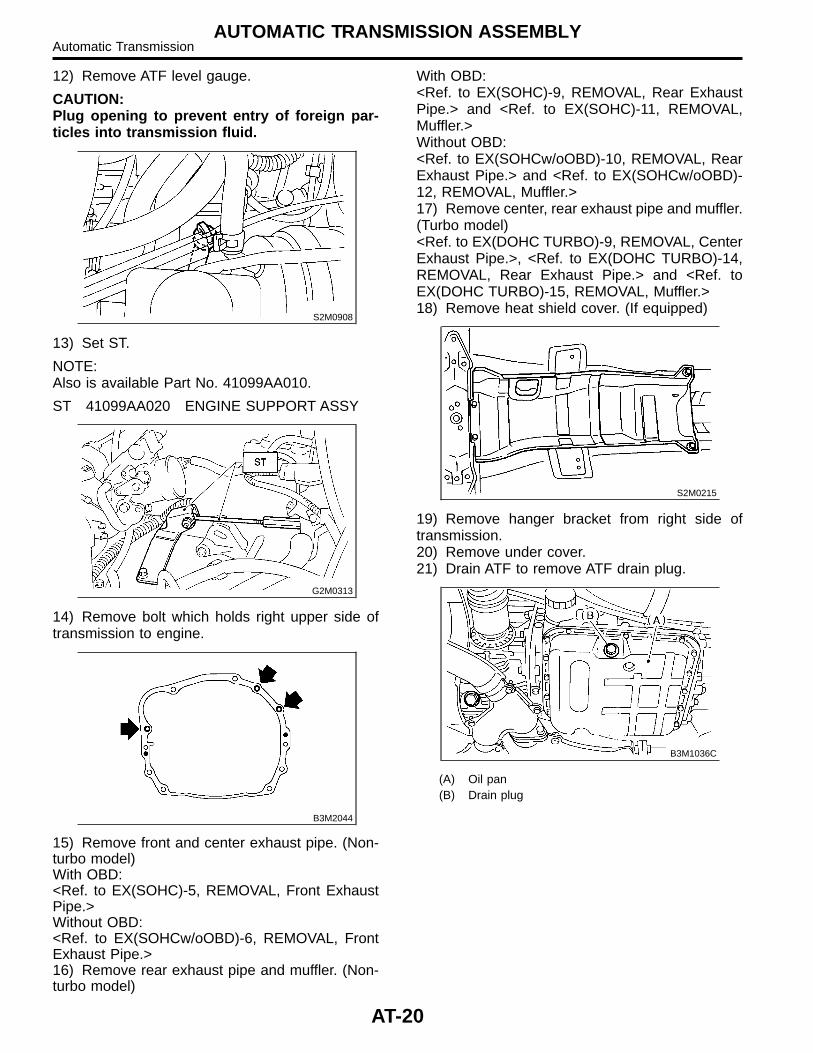
12) Remove ATF level gauge.
CAUTION:Plug opening to prevent entry of foreign par-ticles into transmission fluid.
S2M0908
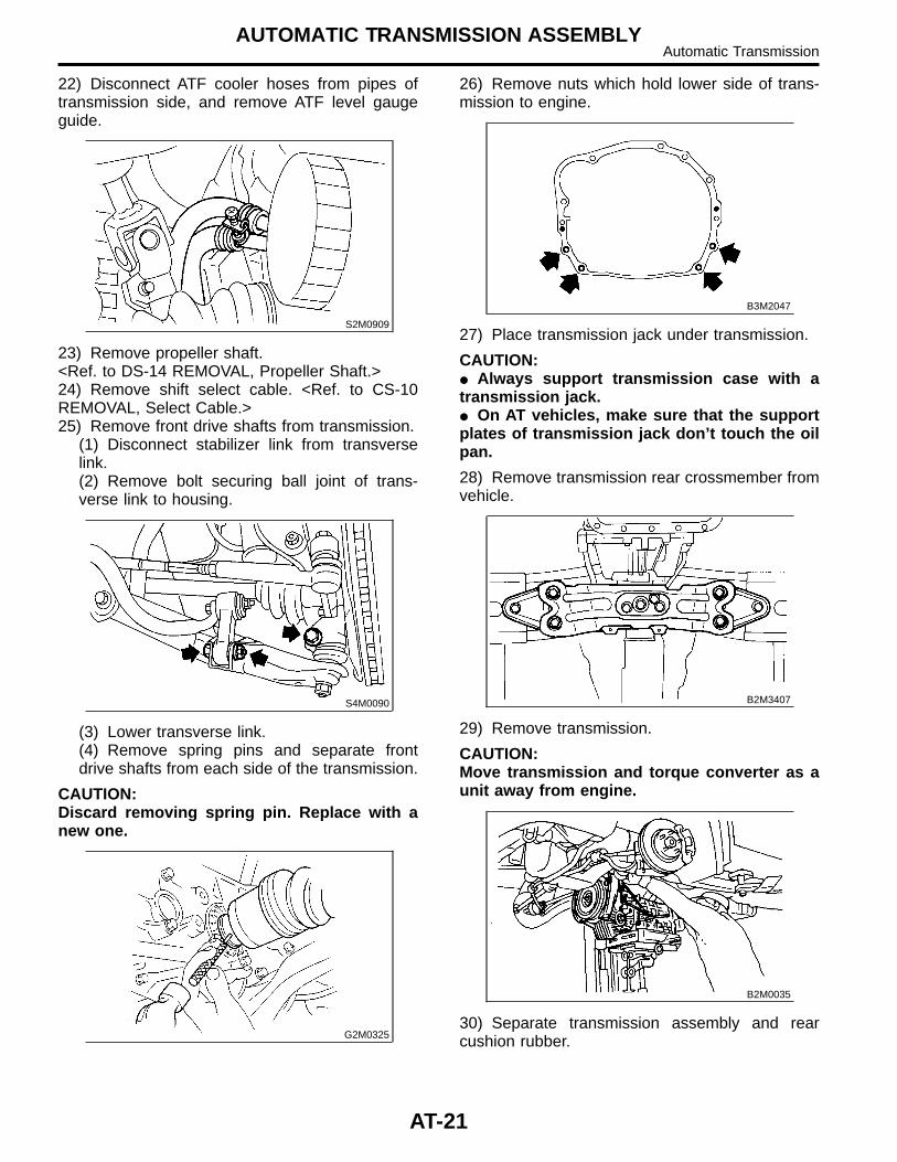
13) Set ST.
NOTE:Also is available Part No. 41099AA010.
ST 41099AA020 ENGINE SUPPORT ASSY
G2M0313
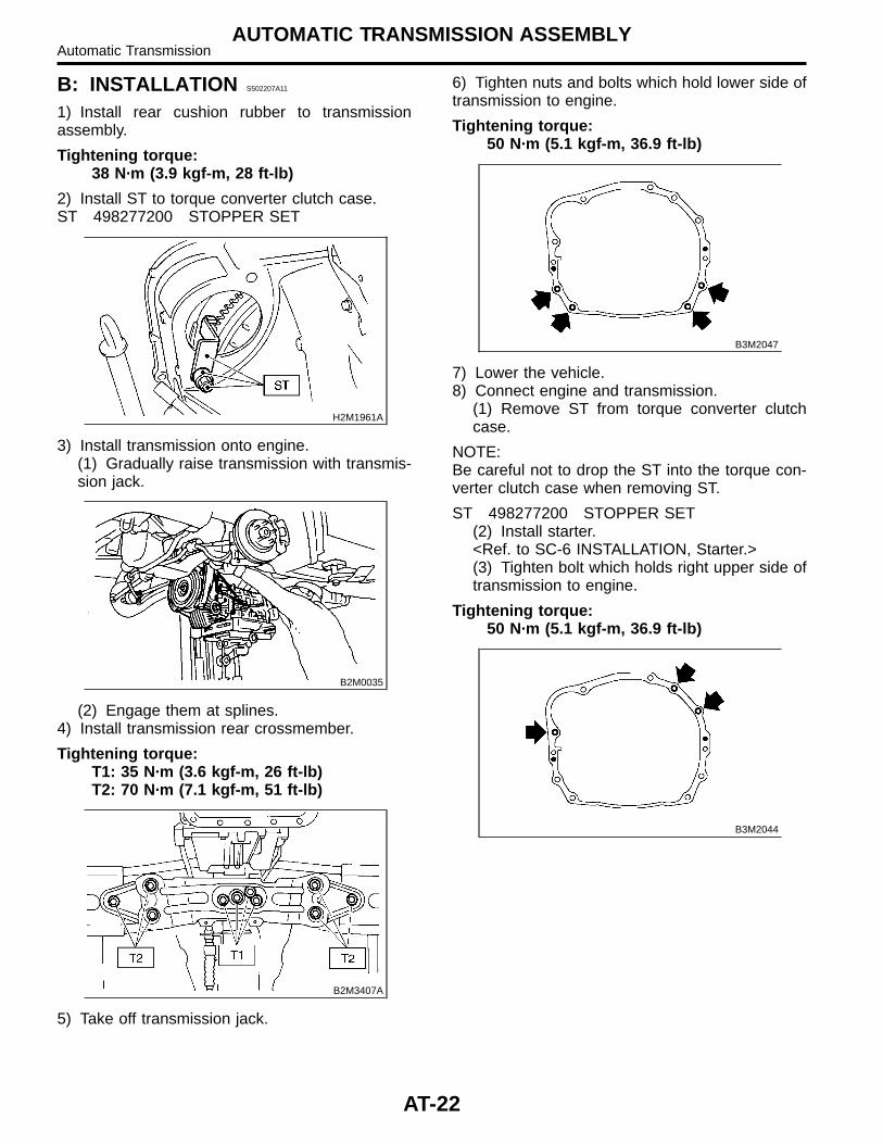
14) Remove bolt which holds right upper side oftransmission to engine.
B3M2044
15) Remove front and center exhaust pipe. (Non-turbo model)With OBD:<Ref. to EX(SOHC)-5, REMOVAL, Front ExhaustPipe.>Without OBD:<Ref. to EX(SOHCw/oOBD)-6, REMOVAL, FrontExhaust Pipe.>16) Remove rear exhaust pipe and muffler. (Non-turbo model)
With OBD:<Ref. to EX(SOHC)-9, REMOVAL, Rear ExhaustPipe.> and <Ref. to EX(SOHC)-11, REMOVAL,Muffler.>Without OBD:<Ref. to EX(SOHCw/oOBD)-10, REMOVAL, RearExhaust Pipe.> and <Ref. to EX(SOHCw/oOBD)-12, REMOVAL, Muffler.>17) Remove center, rear exhaust pipe and muffler.(Turbo model)<Ref. to EX(DOHC TURBO)-9, REMOVAL, CenterExhaust Pipe.>, <Ref. to EX(DOHC TURBO)-14,REMOVAL, Rear Exhaust Pipe.> and <Ref. toEX(DOHC TURBO)-15, REMOVAL, Muffler.>18) Remove heat shield cover. (If equipped)
S2M0215
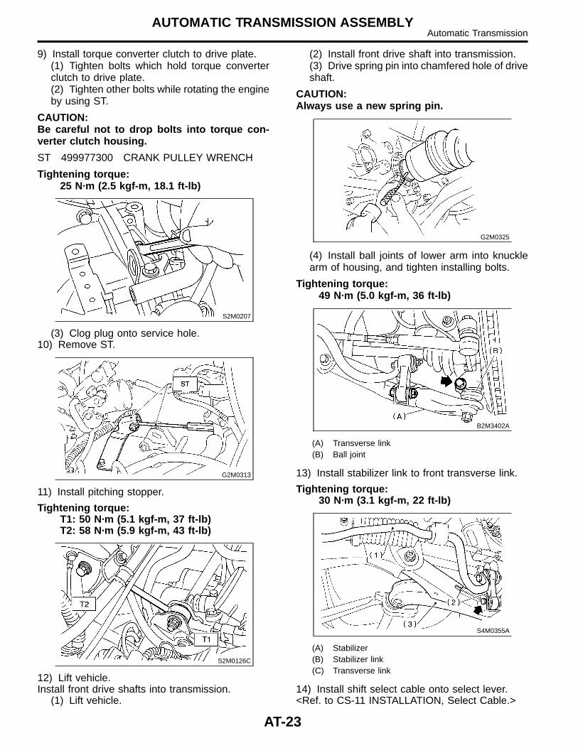
19) Remove hanger bracket from right side oftransmission.20) Remove under cover.21) Drain ATF to remove ATF drain plug.
B3M1036C
(A) Oil pan(B) Drain plug
AT-20
AUTOMATIC TRANSMISSION ASSEMBLYAutomatic Transmission
22) Disconnect ATF cooler hoses from pipes oftransmission side, and remove ATF level gaugeguide.
S2M0909
23) Remove propeller shaft.<Ref. to DS-14 REMOVAL, Propeller Shaft.>24) Remove shift select cable. <Ref. to CS-10REMOVAL, Select Cable.>25) Remove front drive shafts from transmission.
(1) Disconnect stabilizer link from transverselink.(2) Remove bolt securing ball joint of trans-verse link to housing.
S4M0090
(3) Lower transverse link.(4) Remove spring pins and separate frontdrive shafts from each side of the transmission.
CAUTION:Discard removing spring pin. Replace with anew one.
G2M0325
26) Remove nuts which hold lower side of trans-mission to engine.
B3M2047
27) Place transmission jack under transmission.
CAUTION:� Always support transmission case with atransmission jack.� On AT vehicles, make sure that the supportplates of transmission jack don’t touch the oilpan.
28) Remove transmission rear crossmember fromvehicle.
B2M3407
29) Remove transmission.
CAUTION:Move transmission and torque converter as aunit away from engine.
B2M0035
30) Separate transmission assembly and rearcushion rubber.
AT-21
AUTOMATIC TRANSMISSION ASSEMBLYAutomatic Transmission
B: INSTALLATION S502207A11
1) Install rear cushion rubber to transmissionassembly.
Tightening torque:38 N·m (3.9 kgf-m, 28 ft-lb)
2) Install ST to torque converter clutch case.ST 498277200 STOPPER SET
H2M1961A
3) Install transmission onto engine.(1) Gradually raise transmission with transmis-sion jack.
B2M0035
(2) Engage them at splines.4) Install transmission rear crossmember.
Tightening torque:T1: 35 N·m (3.6 kgf-m, 26 ft-lb)T2: 70 N·m (7.1 kgf-m, 51 ft-lb)
B2M3407A
5) Take off transmission jack.
6) Tighten nuts and bolts which hold lower side oftransmission to engine.
Tightening torque:50 N·m (5.1 kgf-m, 36.9 ft-lb)
B3M2047
7) Lower the vehicle.8) Connect engine and transmission.
(1) Remove ST from torque converter clutchcase.
NOTE:Be careful not to drop the ST into the torque con-verter clutch case when removing ST.
ST 498277200 STOPPER SET(2) Install starter.<Ref. to SC-6 INSTALLATION, Starter.>(3) Tighten bolt which holds right upper side oftransmission to engine.
Tightening torque:50 N·m (5.1 kgf-m, 36.9 ft-lb)
B3M2044
AT-22
AUTOMATIC TRANSMISSION ASSEMBLYAutomatic Transmission
9) Install torque converter clutch to drive plate.(1) Tighten bolts which hold torque converterclutch to drive plate.(2) Tighten other bolts while rotating the engineby using ST.
CAUTION:Be careful not to drop bolts into torque con-verter clutch housing.
ST 499977300 CRANK PULLEY WRENCH
Tightening torque:25 N·m (2.5 kgf-m, 18.1 ft-lb)
S2M0207
(3) Clog plug onto service hole.10) Remove ST.
G2M0313
11) Install pitching stopper.
Tightening torque:T1: 50 N·m (5.1 kgf-m, 37 ft-lb)T2: 58 N·m (5.9 kgf-m, 43 ft-lb)
S2M0126C
12) Lift vehicle.Install front drive shafts into transmission.
(1) Lift vehicle.
(2) Install front drive shaft into transmission.(3) Drive spring pin into chamfered hole of driveshaft.
CAUTION:Always use a new spring pin.
G2M0325
(4) Install ball joints of lower arm into knucklearm of housing, and tighten installing bolts.
Tightening torque:49 N·m (5.0 kgf-m, 36 ft-lb)
B2M3402A
(A) Transverse link(B) Ball joint
13) Install stabilizer link to front transverse link.
Tightening torque:30 N·m (3.1 kgf-m, 22 ft-lb)
S4M0355A
(A) Stabilizer(B) Stabilizer link(C) Transverse link
14) Install shift select cable onto select lever.<Ref. to CS-11 INSTALLATION, Select Cable.>
AT-23
AUTOMATIC TRANSMISSION ASSEMBLYAutomatic Transmission
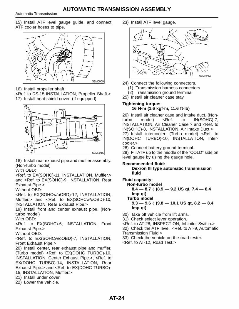
15) Install ATF level gauge guide, and connectATF cooler hoses to pipe.
S2M0909
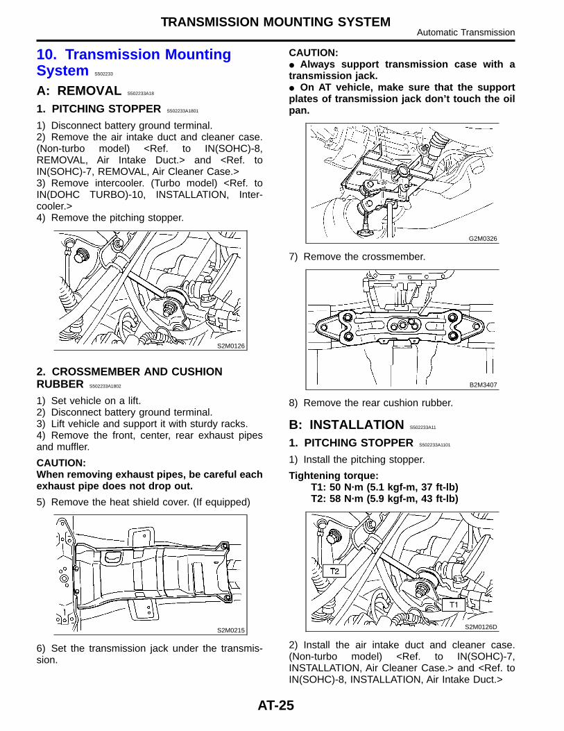
16) Install propeller shaft.<Ref. to DS-15 INSTALLATION, Propeller Shaft.>17) Install heat shield cover. (If equipped)
S2M0215
18) Install rear exhaust pipe and muffler assembly.(Non-turbo model)With OBD:<Ref. to EX(SOHC)-11, INSTALLATION, Muffler.>and <Ref. to EX(SOHC)-9, INSTALLATION, RearExhaust Pipe.>Without OBD:<Ref. to EX(SOHCw/oOBD)-12, INSTALLATION,Muffler.> and <Ref. to EX(SOHCw/oOBD)-10,INSTALLATION, Rear Exhaust Pipe.>19) Install front and center exhaust pipe. (Non-turbo model)With OBD:<Ref. to EX(SOHC)-6, INSTALLATION, FrontExhaust Pipe.>Without OBD:<Ref. to EX(SOHCw/oOBD)-7, INSTALLATION,Front Exhaust Pipe.>20) Install center, rear exhaust pipe and muffler.(Turbo model) <Ref. to EX(DOHC TURBO)-10,INSTALLATION, Center Exhaust Pipe.>, <Ref. toEX(DOHC TURBO)-14, INSTALLATION, RearExhaust Pipe.> and <Ref. to EX(DOHC TURBO)-15, INSTALLATION, Muffler.>21) Install under cover.22) Lower the vehicle.
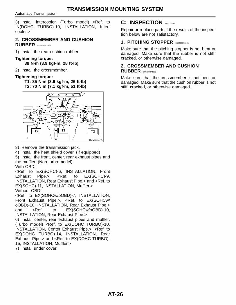
23) Install ATF level gauge.
S2M0214
24) Connect the following connectors.(1) Transmission harness connectors(2) Transmission ground terminal
25) Install air cleaner case stay.
Tightening torque:16 N·m (1.6 kgf-m, 11.6 ft-lb)
26) Install air cleaner case and intake duct. (Non-turbo model) <Ref. to IN(SOHC)-7,INSTALLATION, Air Cleaner Case.> and <Ref. toIN(SOHC)-8, INSTALLATION, Air Intake Duct.>27) Install intercooler. (Turbo model) <Ref. toIN(DOHC TURBO)-10, INSTALLATION, Inter-cooler.>28) Connect battery ground terminal.29) Fill ATF up to the middle of the “COLD” side onlevel gauge by using the gauge hole.
Recommended fluid:Dexron III type automatic transmissionfluid
Fluid capacity:Non-turbo model
8.4 — 8.7 � (8.9 — 9.2 US qt, 7.4 — 8.4Imp qt)
Turbo model9.3 — 9.6 � (9.8 — 10.1 US qt, 8.2 — 8.4Imp qt)
30) Take off vehicle from lift arms.31) Check select lever operation.<Ref. to AT-28, INSPECTION, Inhibitor Switch.>32) Check the ATF level. <Ref. to AT-9, AutomaticTransmission Fluid.>33) Check the vehicle on the road tester.<Ref. to AT-12, Road Test.>
AT-24
AUTOMATIC TRANSMISSION ASSEMBLYAutomatic Transmission
10. Transmission MountingSystem S502233
A: REMOVAL S502233A18
1. PITCHING STOPPER S502233A1801
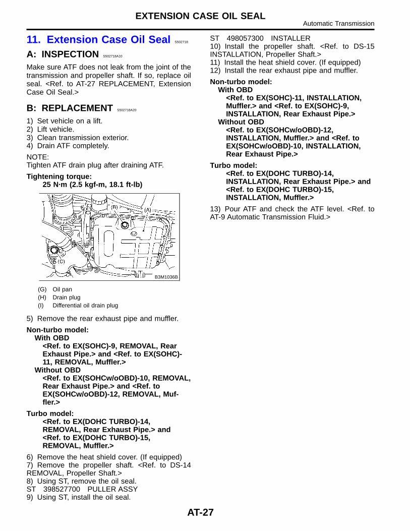
1) Disconnect battery ground terminal.2) Remove the air intake duct and cleaner case.(Non-turbo model) <Ref. to IN(SOHC)-8,REMOVAL, Air Intake Duct.> and <Ref. toIN(SOHC)-7, REMOVAL, Air Cleaner Case.>3) Remove intercooler. (Turbo model) <Ref. toIN(DOHC TURBO)-10, INSTALLATION, Inter-cooler.>4) Remove the pitching stopper.
S2M0126
2. CROSSMEMBER AND CUSHIONRUBBER S502233A1802
1) Set vehicle on a lift.2) Disconnect battery ground terminal.3) Lift vehicle and support it with sturdy racks.4) Remove the front, center, rear exhaust pipesand muffler.
CAUTION:When removing exhaust pipes, be careful eachexhaust pipe does not drop out.
5) Remove the heat shield cover. (If equipped)
S2M0215
6) Set the transmission jack under the transmis-sion.
CAUTION:� Always support transmission case with atransmission jack.� On AT vehicle, make sure that the supportplates of transmission jack don’t touch the oilpan.
G2M0326
7) Remove the crossmember.
B2M3407
8) Remove the rear cushion rubber.
B: INSTALLATION S502233A11
1. PITCHING STOPPER S502233A1101
1) Install the pitching stopper.
Tightening torque:T1: 50 N·m (5.1 kgf-m, 37 ft-lb)T2: 58 N·m (5.9 kgf-m, 43 ft-lb)
S2M0126D
2) Install the air intake duct and cleaner case.(Non-turbo model) <Ref. to IN(SOHC)-7,INSTALLATION, Air Cleaner Case.> and <Ref. toIN(SOHC)-8, INSTALLATION, Air Intake Duct.>
AT-25
TRANSMISSION MOUNTING SYSTEMAutomatic Transmission
3) Install intercooler. (Turbo model) <Ref. toIN(DOHC TURBO)-10, INSTALLATION, Inter-cooler.>
2. CROSSMEMBER AND CUSHIONRUBBER S502233A1102
1) Install the rear cushion rubber.
Tightening torque:38 N·m (3.9 kgf-m, 28 ft-lb)
2) Install the crossmember.
Tightening torque:T1: 35 N·m (3.6 kgf-m, 26 ft-lb)T2: 70 N·m (7.1 kgf-m, 51 ft-lb)
B2M3407A
3) Remove the transmission jack.4) Install the heat shield cover. (If equipped)5) Install the front, center, rear exhaust pipes andthe muffler. (Non-turbo model)With OBD:<Ref. to EX(SOHC)-6, INSTALLATION, FrontExhaust Pipe.>, <Ref. to EX(SOHC)-9,INSTALLATION, Rear Exhaust Pipe.> and <Ref. toEX(SOHC)-11, INSTALLATION, Muffler.>Without OBD:<Ref. to EX(SOHCw/oOBD)-7, INSTALLATION,Front Exhaust Pipe.>, <Ref. to EX(SOHCw/oOBD)-10, INSTALLATION, Rear Exhaust Pipe.>and <Ref. to EX(SOHCw/oOBD)-10,INSTALLATION, Rear Exhaust Pipe.>6) Install center, rear exhaust pipes and muffler.(Turbo model) <Ref. to EX(DOHC TURBO)-10,INSTALLATION, Center Exhaust Pipe.>, <Ref. toEX(DOHC TURBO)-14, INSTALLATION, RearExhaust Pipe.> and <Ref. to EX(DOHC TURBO)-15, INSTALLATION, Muffler.>7) Install under cover.
C: INSPECTION S502233A10
Repair or replace parts if the results of the inspec-tion below are not satisfactory.
1. PITCHING STOPPER S502233A1001
Make sure that the pitching stopper is not bent ordamaged. Make sure that the rubber is not stiff,cracked, or otherwise damaged.
2. CROSSMEMBER AND CUSHIONRUBBER S502233A1002
Make sure that the crossmember is not bent ordamaged. Make sure that the cushion rubber is notstiff, cracked, or otherwise damaged.
AT-26
TRANSMISSION MOUNTING SYSTEMAutomatic Transmission
11. Extension Case Oil Seal S502718
A: INSPECTION S502718A10
Make sure ATF does not leak from the joint of thetransmission and propeller shaft. If so, replace oilseal. <Ref. to AT-27 REPLACEMENT, ExtensionCase Oil Seal.>
B: REPLACEMENT S502718A20
1) Set vehicle on a lift.2) Lift vehicle.3) Clean transmission exterior.4) Drain ATF completely.
NOTE:Tighten ATF drain plug after draining ATF.
Tightening torque:25 N·m (2.5 kgf-m, 18.1 ft-lb)
B3M1036B
(G) Oil pan(H) Drain plug(I) Differential oil drain plug
5) Remove the rear exhaust pipe and muffler.
Non-turbo model:With OBD
<Ref. to EX(SOHC)-9, REMOVAL, RearExhaust Pipe.> and <Ref. to EX(SOHC)-11, REMOVAL, Muffler.>
Without OBD<Ref. to EX(SOHCw/oOBD)-10, REMOVAL,Rear Exhaust Pipe.> and <Ref. toEX(SOHCw/oOBD)-12, REMOVAL, Muf-fler.>
Turbo model:<Ref. to EX(DOHC TURBO)-14,REMOVAL, Rear Exhaust Pipe.> and<Ref. to EX(DOHC TURBO)-15,REMOVAL, Muffler.>
6) Remove the heat shield cover. (If equipped)7) Remove the propeller shaft. <Ref. to DS-14REMOVAL, Propeller Shaft.>8) Using ST, remove the oil seal.ST 398527700 PULLER ASSY9) Using ST, install the oil seal.
ST 498057300 INSTALLER10) Install the propeller shaft. <Ref. to DS-15INSTALLATION, Propeller Shaft.>11) Install the heat shield cover. (If equipped)12) Install the rear exhaust pipe and muffler.
Non-turbo model:With OBD
<Ref. to EX(SOHC)-11, INSTALLATION,Muffler.> and <Ref. to EX(SOHC)-9,INSTALLATION, Rear Exhaust Pipe.>
Without OBD<Ref. to EX(SOHCw/oOBD)-12,INSTALLATION, Muffler.> and <Ref. toEX(SOHCw/oOBD)-10, INSTALLATION,Rear Exhaust Pipe.>
Turbo model:<Ref. to EX(DOHC TURBO)-14,INSTALLATION, Rear Exhaust Pipe.> and<Ref. to EX(DOHC TURBO)-15,INSTALLATION, Muffler.>
13) Pour ATF and check the ATF level. <Ref. toAT-9 Automatic Transmission Fluid.>
AT-27
EXTENSION CASE OIL SEALAutomatic Transmission
12. Inhibitor Switch S502243
A: INSPECTION S502243A10
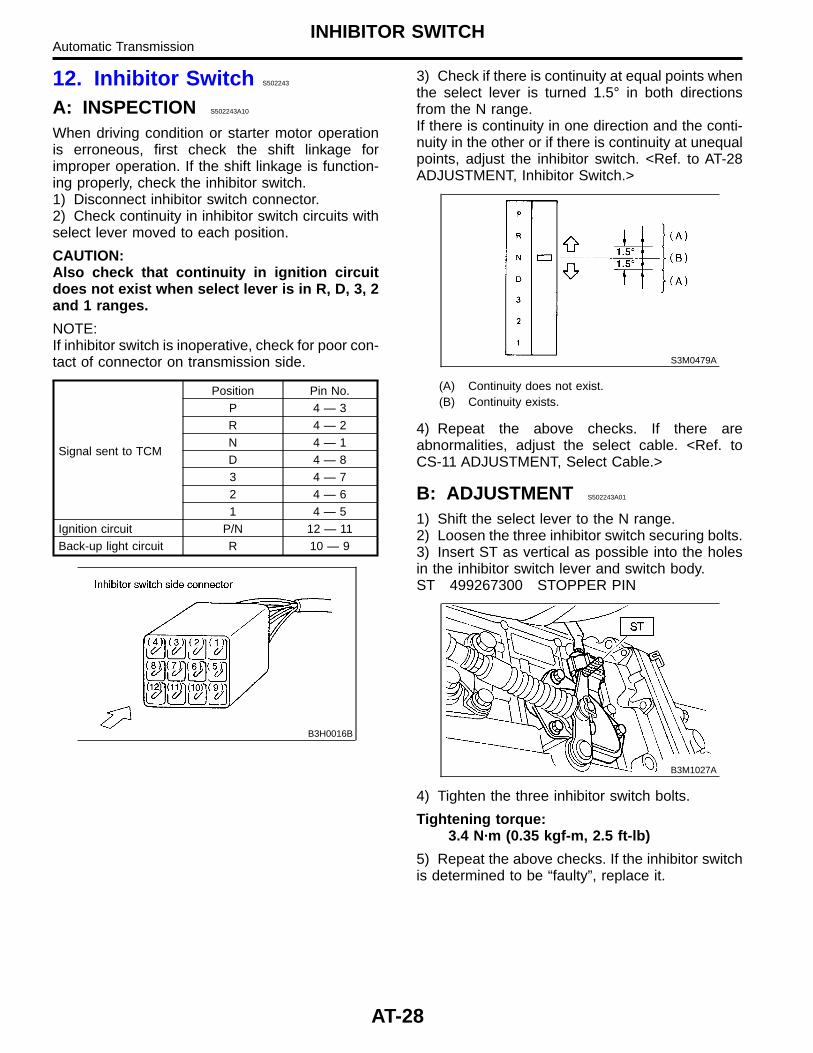
When driving condition or starter motor operationis erroneous, first check the shift linkage forimproper operation. If the shift linkage is function-ing properly, check the inhibitor switch.1) Disconnect inhibitor switch connector.2) Check continuity in inhibitor switch circuits withselect lever moved to each position.
CAUTION:Also check that continuity in ignition circuitdoes not exist when select lever is in R, D, 3, 2and 1 ranges.
NOTE:If inhibitor switch is inoperative, check for poor con-tact of connector on transmission side.
Signal sent to TCM
Position Pin No.P 4 — 3R 4 — 2N 4 — 1D 4 — 83 4 — 72 4 — 61 4 — 5
Ignition circuit P/N 12 — 11Back-up light circuit R 10 — 9
B3H0016B
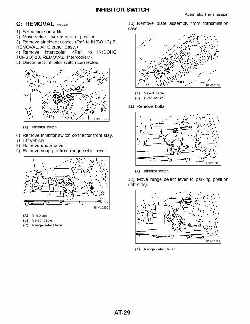
3) Check if there is continuity at equal points whenthe select lever is turned 1.5° in both directionsfrom the N range.If there is continuity in one direction and the conti-nuity in the other or if there is continuity at unequalpoints, adjust the inhibitor switch. <Ref. to AT-28ADJUSTMENT, Inhibitor Switch.>
S3M0479A
(A) Continuity does not exist.(B) Continuity exists.
4) Repeat the above checks. If there areabnormalities, adjust the select cable. <Ref. toCS-11 ADJUSTMENT, Select Cable.>
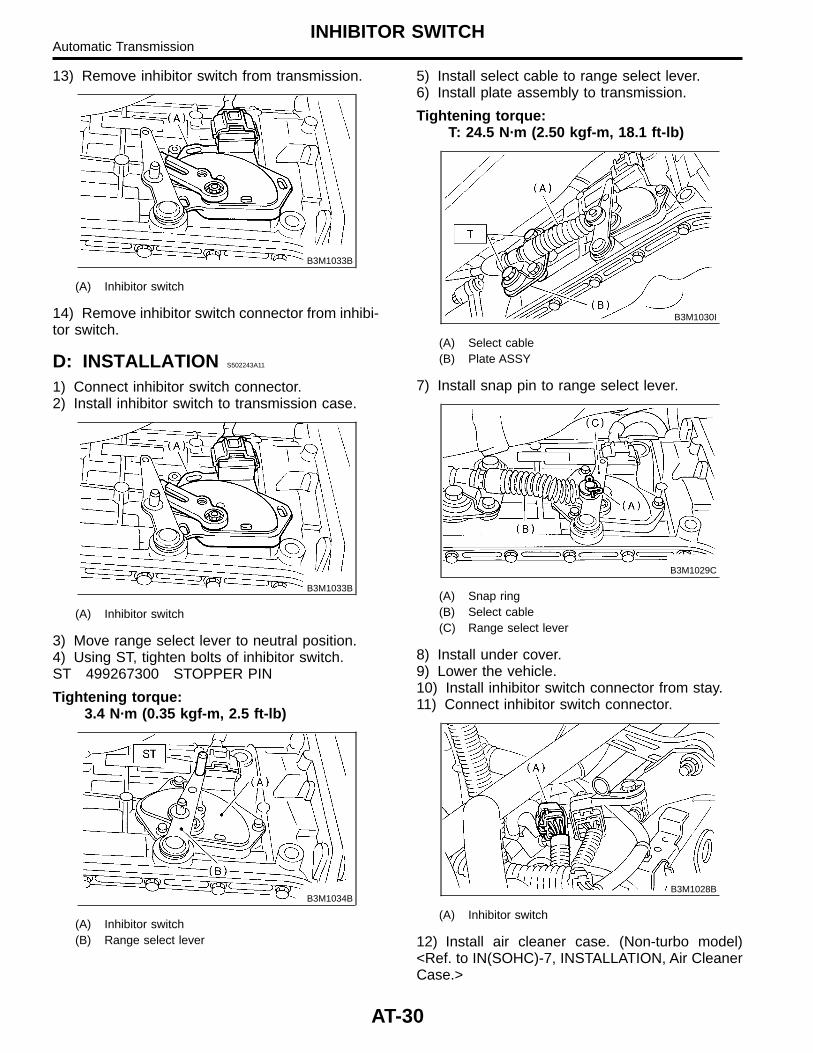
B: ADJUSTMENT S502243A01
1) Shift the select lever to the N range.2) Loosen the three inhibitor switch securing bolts.3) Insert ST as vertical as possible into the holesin the inhibitor switch lever and switch body.ST 499267300 STOPPER PIN
B3M1027A
4) Tighten the three inhibitor switch bolts.
Tightening torque:3.4 N·m (0.35 kgf-m, 2.5 ft-lb)
5) Repeat the above checks. If the inhibitor switchis determined to be “faulty”, replace it.
AT-28
INHIBITOR SWITCHAutomatic Transmission
C: REMOVAL S502243A18
1) Set vehicle on a lift.2) Move select lever to neutral position.3) Remove air cleaner case. <Ref. to IN(SOHC)-7,REMOVAL, Air Cleaner Case.>4) Remove intercooler. <Ref. to IN(DOHCTURBO)-10, REMOVAL, Intercooler.>5) Disconnect inhibitor switch connector.
B3M1028B
(A) Inhibitor switch
6) Remove inhibitor switch connector from stay.7) Lift vehicle.8) Remove under cover.9) Remove snap pin from range select lever.
B3M1029C
(A) Snap pin(B) Select cable(C) Range select lever
10) Remove plate assembly from transmissioncase.
B3M1030H
(A) Select cable(B) Plate ASSY
11) Remove bolts.
B3M1031B
(A) Inhibitor switch
12) Move range select lever to parking position(left side).
B3M1032B
(A) Range select lever
AT-29
INHIBITOR SWITCHAutomatic Transmission
13) Remove inhibitor switch from transmission.
B3M1033B
(A) Inhibitor switch
14) Remove inhibitor switch connector from inhibi-tor switch.
D: INSTALLATION S502243A11
1) Connect inhibitor switch connector.2) Install inhibitor switch to transmission case.
B3M1033B
(A) Inhibitor switch
3) Move range select lever to neutral position.4) Using ST, tighten bolts of inhibitor switch.ST 499267300 STOPPER PIN
Tightening torque:3.4 N·m (0.35 kgf-m, 2.5 ft-lb)
B3M1034B
(A) Inhibitor switch(B) Range select lever
5) Install select cable to range select lever.6) Install plate assembly to transmission.
Tightening torque:T: 24.5 N·m (2.50 kgf-m, 18.1 ft-lb)
B3M1030I
(A) Select cable(B) Plate ASSY
7) Install snap pin to range select lever.
B3M1029C
(A) Snap ring(B) Select cable(C) Range select lever
8) Install under cover.9) Lower the vehicle.10) Install inhibitor switch connector from stay.11) Connect inhibitor switch connector.
B3M1028B
(A) Inhibitor switch
12) Install air cleaner case. (Non-turbo model)<Ref. to IN(SOHC)-7, INSTALLATION, Air CleanerCase.>
AT-30
INHIBITOR SWITCHAutomatic Transmission
13) Install intercooler. <Ref. to IN(DOHCTURBO)-10, INSTALLATION, Intercooler.>14) Inspect inhibitor switch. <Ref. to AT-28INSPECTION, Inhibitor Switch.>
AT-31
INHIBITOR SWITCHAutomatic Transmission
13. Front Vehicle Speed SensorS502709
A: REMOVAL S502709A18
1) Set vehicle on a lift.2) Disconnect battery ground terminal.
G6M0095
3) Remove air cleaner case. (Non-turbo model)<Ref. to IN(SOHC)-7, REMOVAL, Air CleanerCase.>4) Remove intercooler. (Turbo model) <Ref. toIN(DOHC TURBO)-10, REMOVAL, Intercooler.>5) Disconnect transmission connector.
S3M0039B
(A) Transmission connector
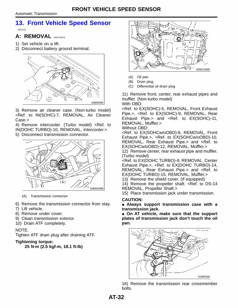
6) Remove the transmission connector from stay.7) Lift vehicle.8) Remove under cover.9) Clean transmission exterior.10) Drain ATF completely.
NOTE:Tighten ATF drain plug after draining ATF.
Tightening torque:25 N·m (2.5 kgf-m, 18.1 ft-lb)
B3M1036B
(A) Oil pan(B) Drain plug(C) Differential oil drain plug
11) Remove front, center, rear exhaust pipes andmuffler. (Non-turbo model)With OBD:<Ref. to EX(SOHC)-5, REMOVAL, Front ExhaustPipe.>, <Ref. to EX(SOHC)-9, REMOVAL, RearExhaust Pipe.> and <Ref. to EX(SOHC)-11,REMOVAL, Muffler.>Without OBD:<Ref. to EX(SOHCw/oOBD)-6, REMOVAL, FrontExhaust Pipe.>, <Ref. to EX(SOHCw/oOBD)-10,REMOVAL, Rear Exhaust Pipe.> and <Ref. toEX(SOHCw/oOBD)-12, REMOVAL, Muffler.>12) Remove center, rear exhaust pipe and muffler.(Turbo model)<Ref. to EX(DOHC TURBO)-9, REMOVAL, CenterExhaust Pipe.>, <Ref. to EX(DOHC TURBO)-14,REMOVAL, Rear Exhaust Pipe.> and <Ref. toEX(DOHC TURBO)-15, REMOVAL, Muffler.>13) Remove the shield cover. (If equipped)14) Remove the propeller shaft. <Ref. to DS-14REMOVAL, Propeller Shaft.>15) Place transmission jack under transmission.
CAUTION:� Always support transmission case with atransmission jack.� On AT vehicle, make sure that the supportplates of transmission jack don’t touch the oilpan.
G2M0326
16) Remove the transmission rear crossmemberbolts.
AT-32
FRONT VEHICLE SPEED SENSORAutomatic Transmission
S2M0221
17) Lower the AT jack.
NOTE:Do not separate the AT jack and transmission.
18) Remove the oil cooler outlet pipe.
CAUTION:When removing outlet pipe, be careful not tolose balls and springs used with retainingscrews.
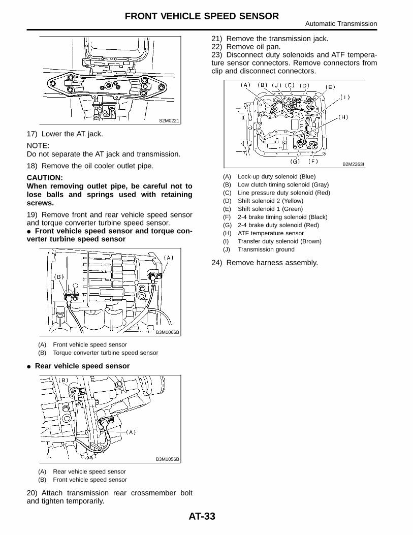
19) Remove front and rear vehicle speed sensorand torque converter turbine speed sensor.� Front vehicle speed sensor and torque con-verter turbine speed sensor
B3M1066B
(A) Front vehicle speed sensor(B) Torque converter turbine speed sensor
� Rear vehicle speed sensor
B3M1056B
(A) Rear vehicle speed sensor(B) Front vehicle speed sensor
20) Attach transmission rear crossmember boltand tighten temporarily.
21) Remove the transmission jack.22) Remove oil pan.23) Disconnect duty solenoids and ATF tempera-ture sensor connectors. Remove connectors fromclip and disconnect connectors.
B2M2263I
(A) Lock-up duty solenoid (Blue)(B) Low clutch timing solenoid (Gray)(C) Line pressure duty solenoid (Red)(D) Shift solenoid 2 (Yellow)(E) Shift solenoid 1 (Green)(F) 2-4 brake timing solenoid (Black)(G) 2-4 brake duty solenoid (Red)(H) ATF temperature sensor(I) Transfer duty solenoid (Brown)(J) Transmission ground
24) Remove harness assembly.
AT-33
FRONT VEHICLE SPEED SENSORAutomatic Transmission
B: INSTALLATION S502709A11
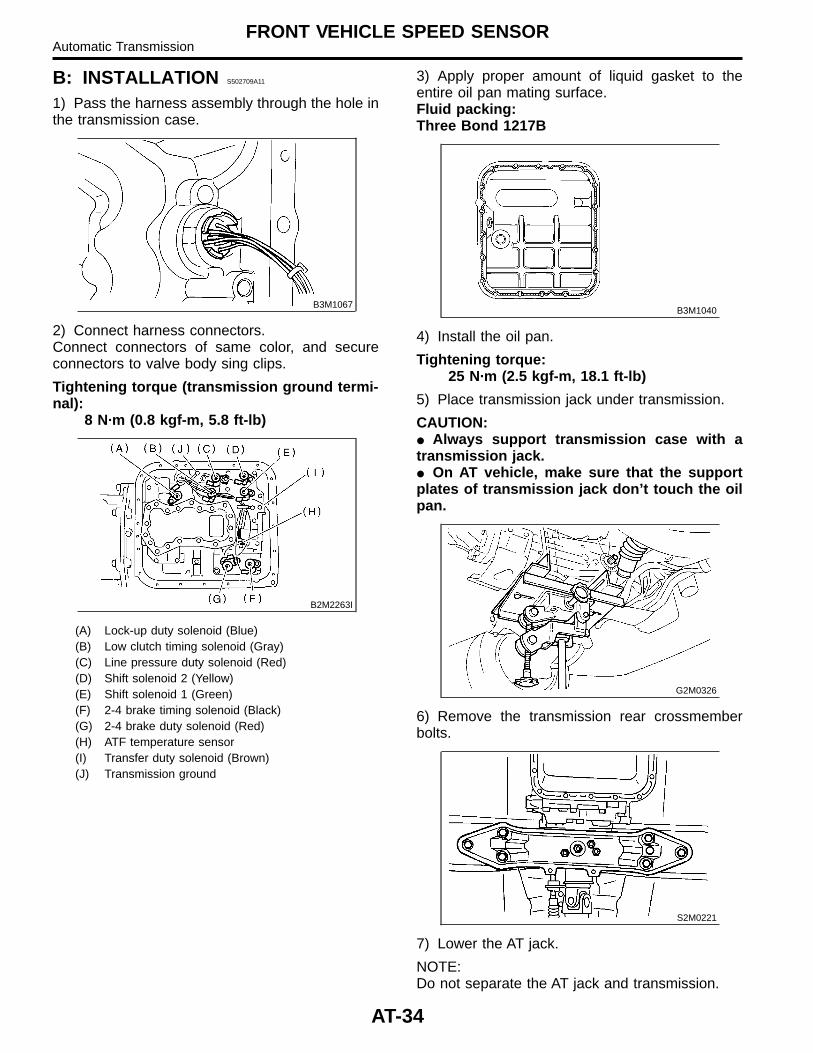
1) Pass the harness assembly through the hole inthe transmission case.
B3M1067
2) Connect harness connectors.Connect connectors of same color, and secureconnectors to valve body sing clips.
Tightening torque (transmission ground termi-nal):
8 N·m (0.8 kgf-m, 5.8 ft-lb)
B2M2263I
(A) Lock-up duty solenoid (Blue)(B) Low clutch timing solenoid (Gray)(C) Line pressure duty solenoid (Red)(D) Shift solenoid 2 (Yellow)(E) Shift solenoid 1 (Green)(F) 2-4 brake timing solenoid (Black)(G) 2-4 brake duty solenoid (Red)(H) ATF temperature sensor(I) Transfer duty solenoid (Brown)(J) Transmission ground
3) Apply proper amount of liquid gasket to theentire oil pan mating surface.Fluid packing:Three Bond 1217B
B3M1040
4) Install the oil pan.
Tightening torque:25 N·m (2.5 kgf-m, 18.1 ft-lb)
5) Place transmission jack under transmission.
CAUTION:� Always support transmission case with atransmission jack.� On AT vehicle, make sure that the supportplates of transmission jack don’t touch the oilpan.
G2M0326
6) Remove the transmission rear crossmemberbolts.
S2M0221
7) Lower the AT jack.
NOTE:Do not separate the AT jack and transmission.
AT-34
FRONT VEHICLE SPEED SENSORAutomatic Transmission
8) Remove the oil cooler outlet pipe.
CAUTION:When removing outlet pipe, be careful not tolose balls and springs used with retainingscrews.
9) Install the front and rear vehicle speed sensor,and also the torque converter turbine speedsensor, and then fasten the harness.
Tightening torque:7 N·m (0.7 kgf-m, 5.1 ft-lb)
10) Install oil cooler outlet pipe.
CAUTION:Be sure to use a new aluminum washer.
Tightening torque:25 N·m (2.5 kgf-m, 18.1 ft-lb)
11) Install transmission rear crossmember bolts.
Tightening torque:75 N·m (7.6 kgf-m, 55 ft-lb)
12) Install propeller shaft. <Ref. to DS-15INSTALLATION, Propeller Shaft.>13) Install shield cover. (If equipped)14) Install front, center, rear exhaust pipes andmuffler. (Non-turbo model)With OBD:<Ref. to EX(SOHC)-6, INSTALLATION, FrontExhaust Pipe.>, <Ref. to EX(SOHC)-9,INSTALLATION, Rear Exhaust Pipe.> and <Ref. toEX(SOHC)-11, REMOVAL, Muffler.>Without OBD:<Ref. to EX(SOHCw/oOBD)-7, INSTALLATION,Front Exhaust Pipe.>, <Ref. to EX(SOHCw/oOBD)-10, INSTALLATION, Rear Exhaust Pipe.>and <Ref. to EX(SOHCw/oOBD)-12,INSTALLATION, Muffler.>15) Install center, rear exhaust pipe and muffler.(Turbo model) <Ref. to EX(DOHC TURBO)-10,INSTALLATION, Center Exhaust Pipe.>, <Ref. toEX(DOHC TURBO)-14, INSTALLATION, RearExhaust Pipe.> and <Ref. to EX(DOHC TURBO)-15, INSTALLATION, Muffler.>16) Install under cover. (Turbo model)17) Lower the vehicle.18) Install the transmission connector to the stay.19) Install air cleaner case. (Non-turbo model)<Ref. to IN(SOHC)-7, INSTALLATION, Air CleanerCase.>20) Install intercooler. (Turbo model) <Ref. toIN(DOHC TURBO)-10, INSTALLATION, Inter-cooler.>
AT-35
FRONT VEHICLE SPEED SENSORAutomatic Transmission
14. Rear Vehicle Speed SensorS502710
A: REMOVAL S502710A18
When removing the rear vehicle speed sensor,refer to “Front Vehicle Speed Sensor.” <Ref. toAT-32 REMOVAL, Front Vehicle Speed Sensor.>
B: INSTALLATION S502710A11
When installing the rear vehicle speed sensor,refer to “Front Vehicle Speed Sensor.” <Ref. toAT-34 INSTALLATION, Front Vehicle Speed Sen-sor.>
AT-36
REAR VEHICLE SPEED SENSORAutomatic Transmission
15. Torque Converter TurbineSpeed Sensor S502711
A: REMOVAL S502711A18
When removing the torque converter turbine speedsensor, refer to “Front Vehicle Speed Sensor.”<Ref. to AT-32 REMOVAL, Front Vehicle SpeedSensor.>
B: INSTALLATION S502711A11
When installing the torque converter turbine speedsensor, refer to “Front Vehicle Speed Sensor.”<Ref. to AT-34 INSTALLATION, Front VehicleSpeed Sensor.>
AT-37
TORQUE CONVERTER TURBINE SPEED SENSORAutomatic Transmission
16. Control Valve Body S502564
A: REMOVAL S502564A18
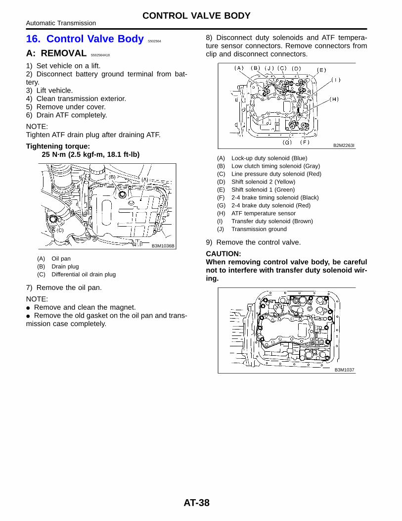
1) Set vehicle on a lift.2) Disconnect battery ground terminal from bat-tery.3) Lift vehicle.4) Clean transmission exterior.5) Remove under cover.6) Drain ATF completely.
NOTE:Tighten ATF drain plug after draining ATF.
Tightening torque:25 N·m (2.5 kgf-m, 18.1 ft-lb)
B3M1036B
(A) Oil pan(B) Drain plug(C) Differential oil drain plug
7) Remove the oil pan.
NOTE:� Remove and clean the magnet.� Remove the old gasket on the oil pan and trans-mission case completely.
8) Disconnect duty solenoids and ATF tempera-ture sensor connectors. Remove connectors fromclip and disconnect connectors.
B2M2263I
(A) Lock-up duty solenoid (Blue)(B) Low clutch timing solenoid (Gray)(C) Line pressure duty solenoid (Red)(D) Shift solenoid 2 (Yellow)(E) Shift solenoid 1 (Green)(F) 2-4 brake timing solenoid (Black)(G) 2-4 brake duty solenoid (Red)(H) ATF temperature sensor(I) Transfer duty solenoid (Brown)(J) Transmission ground
9) Remove the control valve.
CAUTION:When removing control valve body, be carefulnot to interfere with transfer duty solenoid wir-ing.
B3M1037
AT-38
CONTROL VALVE BODYAutomatic Transmission
B: INSTALLATION S502564A11
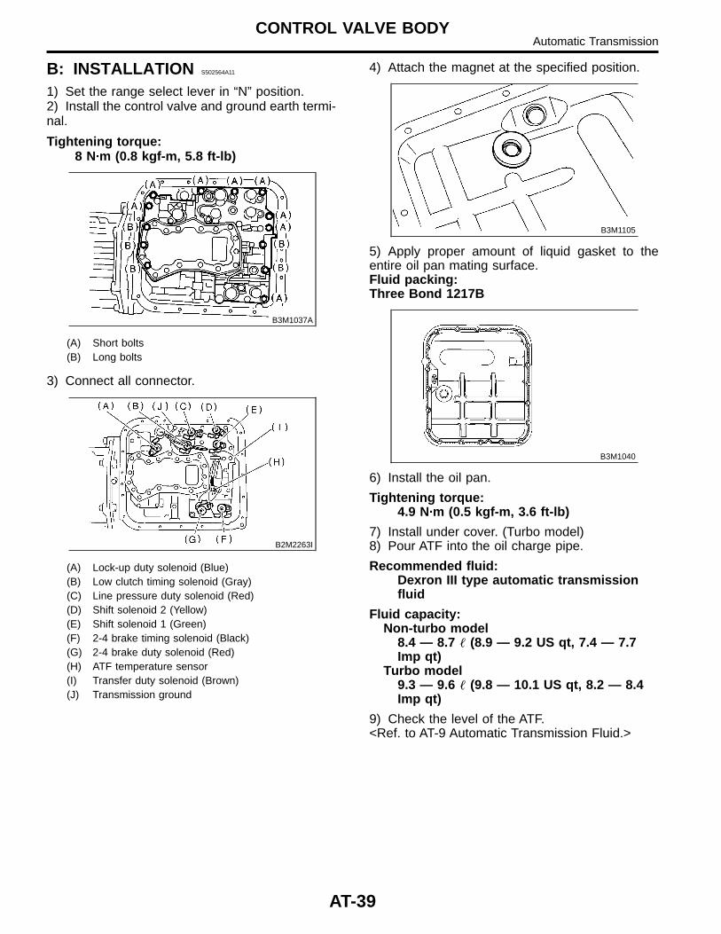
1) Set the range select lever in “N” position.2) Install the control valve and ground earth termi-nal.
Tightening torque:8 N·m (0.8 kgf-m, 5.8 ft-lb)
B3M1037A
(A) Short bolts(B) Long bolts
3) Connect all connector.
B2M2263I
(A) Lock-up duty solenoid (Blue)(B) Low clutch timing solenoid (Gray)(C) Line pressure duty solenoid (Red)(D) Shift solenoid 2 (Yellow)(E) Shift solenoid 1 (Green)(F) 2-4 brake timing solenoid (Black)(G) 2-4 brake duty solenoid (Red)(H) ATF temperature sensor(I) Transfer duty solenoid (Brown)(J) Transmission ground
4) Attach the magnet at the specified position.
B3M1105
5) Apply proper amount of liquid gasket to theentire oil pan mating surface.Fluid packing:Three Bond 1217B
B3M1040
6) Install the oil pan.
Tightening torque:4.9 N·m (0.5 kgf-m, 3.6 ft-lb)
7) Install under cover. (Turbo model)8) Pour ATF into the oil charge pipe.
Recommended fluid:Dexron III type automatic transmissionfluid
Fluid capacity:Non-turbo model
8.4 — 8.7 � (8.9 — 9.2 US qt, 7.4 — 7.7Imp qt)
Turbo model9.3 — 9.6 � (9.8 — 10.1 US qt, 8.2 — 8.4Imp qt)
9) Check the level of the ATF.<Ref. to AT-9 Automatic Transmission Fluid.>
AT-39
CONTROL VALVE BODYAutomatic Transmission
C: DISASSEMBLY S502564A06
Refer to “AUTOMATIC TRANSMISSION” <Pub.No. G0853ZE> a separate publication.
D: ASSEMBLY S502564A02
Refer to “AUTOMATIC TRANSMISSION” <Pub.No. G0853ZE> a separate publication.
E: INSPECTION S502564A10
Refer to “AUTOMATIC TRANSMISSION” <Pub.No. G0853ZE> a separate publication.
AT-40
CONTROL VALVE BODYAutomatic Transmission
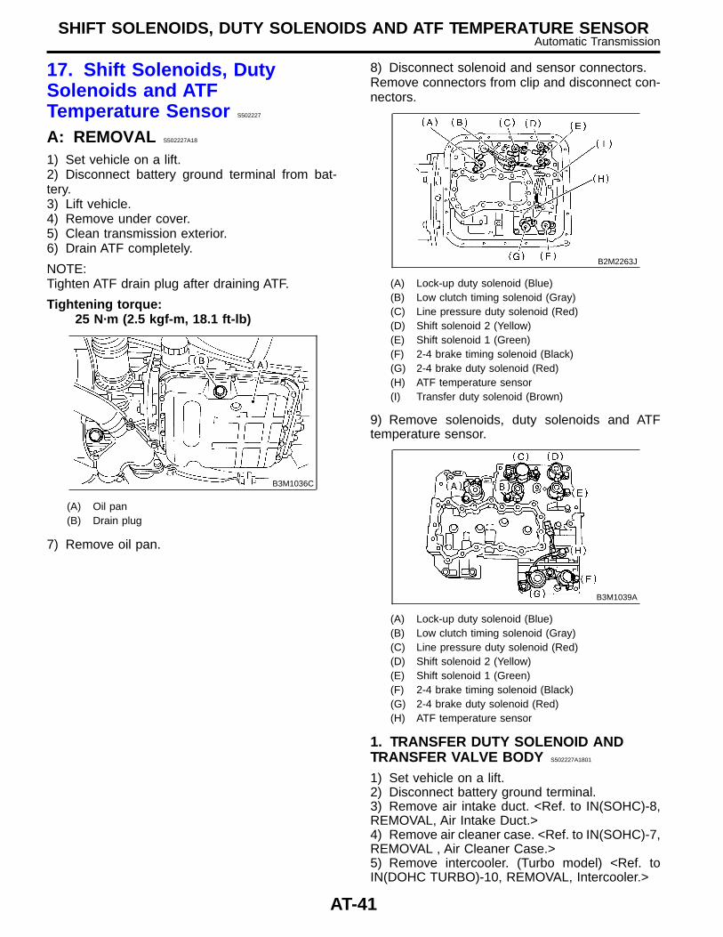
17. Shift Solenoids, DutySolenoids and ATFTemperature Sensor S502227
A: REMOVAL S502227A18
1) Set vehicle on a lift.2) Disconnect battery ground terminal from bat-tery.3) Lift vehicle.4) Remove under cover.5) Clean transmission exterior.6) Drain ATF completely.
NOTE:Tighten ATF drain plug after draining ATF.
Tightening torque:25 N·m (2.5 kgf-m, 18.1 ft-lb)
B3M1036C
(A) Oil pan(B) Drain plug
7) Remove oil pan.
8) Disconnect solenoid and sensor connectors.Remove connectors from clip and disconnect con-nectors.
B2M2263J
(A) Lock-up duty solenoid (Blue)(B) Low clutch timing solenoid (Gray)(C) Line pressure duty solenoid (Red)(D) Shift solenoid 2 (Yellow)(E) Shift solenoid 1 (Green)(F) 2-4 brake timing solenoid (Black)(G) 2-4 brake duty solenoid (Red)(H) ATF temperature sensor(I) Transfer duty solenoid (Brown)
9) Remove solenoids, duty solenoids and ATFtemperature sensor.
B3M1039A
(A) Lock-up duty solenoid (Blue)(B) Low clutch timing solenoid (Gray)(C) Line pressure duty solenoid (Red)(D) Shift solenoid 2 (Yellow)(E) Shift solenoid 1 (Green)(F) 2-4 brake timing solenoid (Black)(G) 2-4 brake duty solenoid (Red)(H) ATF temperature sensor
1. TRANSFER DUTY SOLENOID ANDTRANSFER VALVE BODY S502227A1801
1) Set vehicle on a lift.2) Disconnect battery ground terminal.3) Remove air intake duct. <Ref. to IN(SOHC)-8,REMOVAL, Air Intake Duct.>4) Remove air cleaner case. <Ref. to IN(SOHC)-7,REMOVAL , Air Cleaner Case.>5) Remove intercooler. (Turbo model) <Ref. toIN(DOHC TURBO)-10, REMOVAL, Intercooler.>
AT-41
SHIFT SOLENOIDS, DUTY SOLENOIDS AND ATF TEMPERATURE SENSORAutomatic Transmission
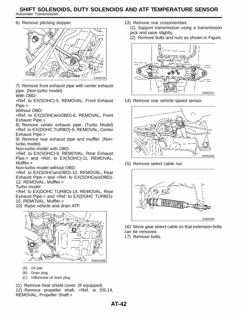
6) Remove pitching stopper.
S2M0126
7) Remove front exhaust pipe with center exhaustpipe. (Non-turbo model)With OBD:<Ref. to EX(SOHC)-5, REMOVAL, Front ExhaustPipe.>Without OBD:<Ref. to EX(SOHCw/oOBD)-6, REMOVAL, FrontExhaust Pipe.>8) Remove center exhaust pipe. (Turbo Model)<Ref. to EX(DOHC TURBO)-9, REMOVAL, CenterExhaust Pipe.>9) Remove rear exhaust pipe and muffler. (Non-turbo model)Non-turbo model with OBD:<Ref. to EX(SOHC)-9, REMOVAL, Rear ExhaustPipe.> and <Ref. to EX(SOHC)-11, REMOVAL,Muffler.>Non-turbo model without OBD:<Ref. to EX(SOHCw/oOBD)-10, REMOVAL, RearExhaust Pipe.> and <Ref. to EX(SOHCw/oOBD)-12, REMOVAL, Muffler.>Turbo model:<Ref. to EX(DOHC TURBO)-14, REMOVAL, RearExhaust Pipe.> and <Ref. to EX(DOHC TURBO)-15, REMOVAL, Muffler.>10) Raise vehicle and drain ATF.
B3M1036B
(A) Oil pan(B) Drain plug(C) Differential oil drain plug
11) Remove heat shield cover. (If equipped)12) Remove propeller shaft. <Ref. to DS-14,REMOVAL, Propeller Shaft.>
13) Remove rear crossmember.(1) Support transmission using a transmissionjack and raise slightly.(2) Remove bolts and nuts as shown in Figure.
S2M0221
14) Remove rear vehicle speed sensor.
B3M1043
15) Remove select cable nut.
G3M0308
16) Move gear select cable so that extension boltscan be removed.17) Remove bolts.
AT-42
SHIFT SOLENOIDS, DUTY SOLENOIDS AND ATF TEMPERATURE SENSORAutomatic Transmission
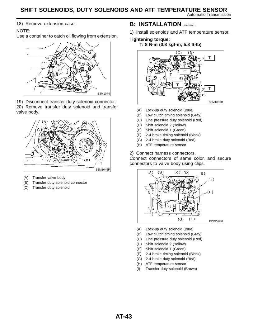
18) Remove extension case.
NOTE:Use a container to catch oil flowing from extension.
B3M1044
19) Disconnect transfer duty solenoid connector.20) Remove transfer duty solenoid and transfervalve body.
B3M1045F
(A) Transfer valve body(B) Transfer duty solenoid connector(C) Transfer duty solenoid
B: INSTALLATION S502227A11
1) Install solenoids and ATF temperature sensor.
Tightening torque:T: 8 N·m (0.8 kgf-m, 5.8 ft-lb)
B3M1039B
(A) Lock-up duty solenoid (Blue)(B) Low clutch timing solenoid (Gray)(C) Line pressure duty solenoid (Red)(D) Shift solenoid 2 (Yellow)(E) Shift solenoid 1 (Green)(F) 2-4 brake timing solenoid (Black)(G) 2-4 brake duty solenoid (Red)(H) ATF temperature sensor
2) Connect harness connectors.Connect connectors of same color, and secureconnectors to valve body using clips.
B2M2263J
(A) Lock-up duty solenoid (Blue)(B) Low clutch timing solenoid (Gray)(C) Line pressure duty solenoid (Red)(D) Shift solenoid 2 (Yellow)(E) Shift solenoid 1 (Green)(F) 2-4 brake timing solenoid (Black)(G) 2-4 brake duty solenoid (Red)(H) ATF temperature sensor(I) Transfer duty solenoid (Brown)
AT-43
SHIFT SOLENOIDS, DUTY SOLENOIDS AND ATF TEMPERATURE SENSORAutomatic Transmission
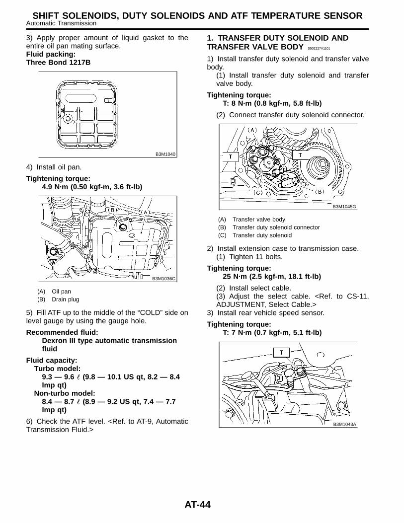
3) Apply proper amount of liquid gasket to theentire oil pan mating surface.Fluid packing:Three Bond 1217B
B3M1040
4) Install oil pan.
Tightening torque:4.9 N·m (0.50 kgf-m, 3.6 ft-lb)
B3M1036C
(A) Oil pan(B) Drain plug
5) Fill ATF up to the middle of the “COLD” side onlevel gauge by using the gauge hole.
Recommended fluid:Dexron III type automatic transmissionfluid
Fluid capacity:Turbo model:
9.3 — 9.6 � (9.8 — 10.1 US qt, 8.2 — 8.4Imp qt)
Non-turbo model:8.4 — 8.7 � (8.9 — 9.2 US qt, 7.4 — 7.7Imp qt)
6) Check the ATF level. <Ref. to AT-9, AutomaticTransmission Fluid.>
1. TRANSFER DUTY SOLENOID ANDTRANSFER VALVE BODY S502227A1101
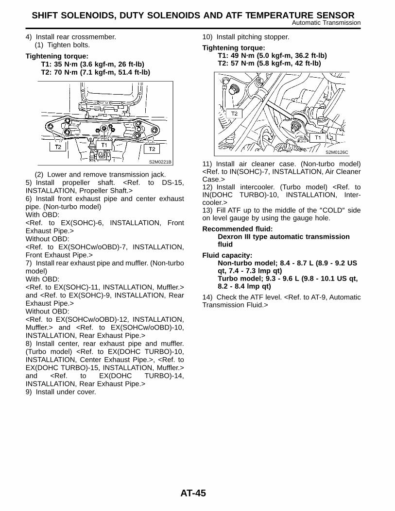
1) Install transfer duty solenoid and transfer valvebody.
(1) Install transfer duty solenoid and transfervalve body.
Tightening torque:T: 8 N·m (0.8 kgf-m, 5.8 ft-lb)
(2) Connect transfer duty solenoid connector.
B3M1045G
(A) Transfer valve body(B) Transfer duty solenoid connector(C) Transfer duty solenoid
2) Install extension case to transmission case.(1) Tighten 11 bolts.
Tightening torque:25 N·m (2.5 kgf-m, 18.1 ft-lb)
(2) Install select cable.(3) Adjust the select cable. <Ref. to CS-11,ADJUSTMENT, Select Cable.>
3) Install rear vehicle speed sensor.
Tightening torque:T: 7 N·m (0.7 kgf-m, 5.1 ft-lb)
B3M1043A
AT-44
SHIFT SOLENOIDS, DUTY SOLENOIDS AND ATF TEMPERATURE SENSORAutomatic Transmission
4) Install rear crossmember.(1) Tighten bolts.
Tightening torque:T1: 35 N·m (3.6 kgf-m, 26 ft-lb)T2: 70 N·m (7.1 kgf-m, 51.4 ft-lb)
S2M0221B
(2) Lower and remove transmission jack.5) Install propeller shaft. <Ref. to DS-15,INSTALLATION, Propeller Shaft.>6) Install front exhaust pipe and center exhaustpipe. (Non-turbo model)With OBD:<Ref. to EX(SOHC)-6, INSTALLATION, FrontExhaust Pipe.>Without OBD:<Ref. to EX(SOHCw/oOBD)-7, INSTALLATION,Front Exhaust Pipe.>7) Install rear exhaust pipe and muffler. (Non-turbomodel)With OBD:<Ref. to EX(SOHC)-11, INSTALLATION, Muffler.>and <Ref. to EX(SOHC)-9, INSTALLATION, RearExhaust Pipe.>Without OBD:<Ref. to EX(SOHCw/oOBD)-12, INSTALLATION,Muffler.> and <Ref. to EX(SOHCw/oOBD)-10,INSTALLATION, Rear Exhaust Pipe.>8) Install center, rear exhaust pipe and muffler.(Turbo model) <Ref. to EX(DOHC TURBO)-10,INSTALLATION, Center Exhaust Pipe.>, <Ref. toEX(DOHC TURBO)-15, INSTALLATION, Muffler.>and <Ref. to EX(DOHC TURBO)-14,INSTALLATION, Rear Exhaust Pipe.>9) Install under cover.
10) Install pitching stopper.
Tightening torque:T1: 49 N·m (5.0 kgf-m, 36.2 ft-lb)T2: 57 N·m (5.8 kgf-m, 42 ft-lb)
S2M0126C
11) Install air cleaner case. (Non-turbo model)<Ref. to IN(SOHC)-7, INSTALLATION, Air CleanerCase.>12) Install intercooler. (Turbo model) <Ref. toIN(DOHC TURBO)-10, INSTALLATION, Inter-cooler.>13) Fill ATF up to the middle of the ″COLD″ sideon level gauge by using the gauge hole.
Recommended fluid:Dexron III type automatic transmissionfluid
Fluid capacity:Non-turbo model; 8.4 - 8.7 L (8.9 - 9.2 USqt, 7.4 - 7.3 lmp qt)Turbo model; 9.3 - 9.6 L (9.8 - 10.1 US qt,8.2 - 8.4 lmp qt)
14) Check the ATF level. <Ref. to AT-9, AutomaticTransmission Fluid.>
AT-45
SHIFT SOLENOIDS, DUTY SOLENOIDS AND ATF TEMPERATURE SENSORAutomatic Transmission
18. ATF Filter S502226
A: REMOVAL S502226A18
NOTE:The ATF filter is maintenance free.
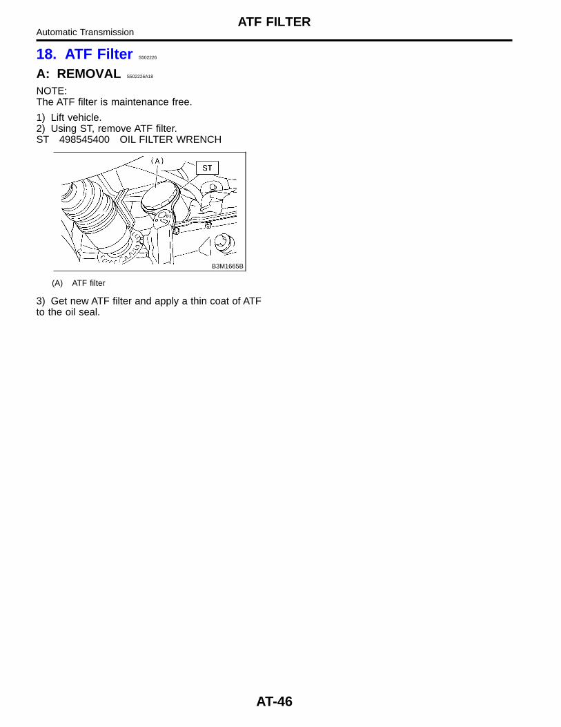
1) Lift vehicle.2) Using ST, remove ATF filter.ST 498545400 OIL FILTER WRENCH
B3M1665B
(A) ATF filter
3) Get new ATF filter and apply a thin coat of ATFto the oil seal.
AT-46
ATF FILTERAutomatic Transmission
B: INSTALLATION S502226A11
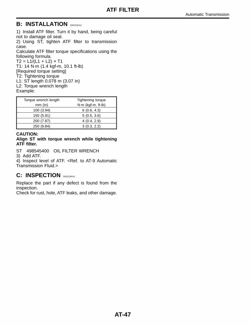
1) Install ATF filter. Turn it by hand, being carefulnot to damage oil seal.2) Using ST, tighten ATF filter to transmissioncase.Calculate ATF filter torque specifications using thefollowing formula.T2 = L1/(L1 + L2) × T1T1: 14 N·m (1.4 kgf-m, 10.1 ft-lb)[Required torque setting]T2: Tightening torqueL1: ST length 0.078 m (3.07 in)L2: Torque wrench lengthExample:
Torque wrench lengthmm (in)
Tightening torqueN·m (kgf-m, ft-lb)
100 (3.94) 6 (0.6, 4.3)150 (5.91) 5 (0.5, 3.6)200 (7.87) 4 (0.4, 2.9)250 (9.84) 3 (0.3, 2.2)
CAUTION:Align ST with torque wrench while tighteningATF filter.
ST 498545400 OIL FILTER WRENCH3) Add ATF.4) Inspect level of ATF. <Ref. to AT-9 AutomaticTransmission Fluid.>
C: INSPECTION S502226A10
Replace the part if any defect is found from theinspection.Check for rust, hole, ATF leaks, and other damage.
AT-47
ATF FILTERAutomatic Transmission
19. Transmission ControlModule (TCM) S502225
A: REMOVAL S502225A18
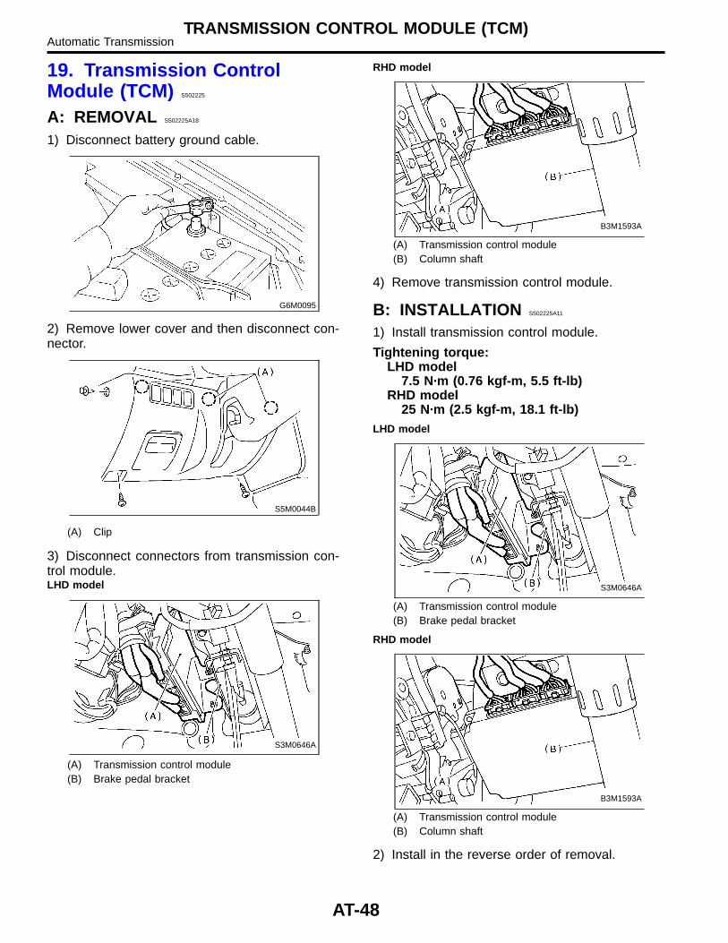
1) Disconnect battery ground cable.
G6M0095
2) Remove lower cover and then disconnect con-nector.
S5M0044B
(A) Clip
3) Disconnect connectors from transmission con-trol module.LHD model
S3M0646A
(A) Transmission control module(B) Brake pedal bracket
RHD model
B3M1593A
(A) Transmission control module(B) Column shaft
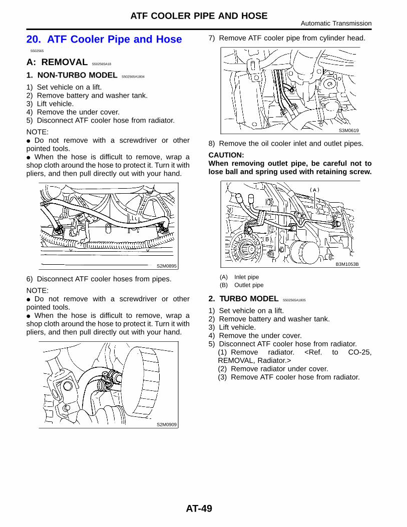
4) Remove transmission control module.
B: INSTALLATION S502225A11
1) Install transmission control module.
Tightening torque:LHD model
7.5 N·m (0.76 kgf-m, 5.5 ft-lb)RHD model
25 N·m (2.5 kgf-m, 18.1 ft-lb)LHD model
S3M0646A
(A) Transmission control module(B) Brake pedal bracket
RHD model
B3M1593A
(A) Transmission control module(B) Column shaft
2) Install in the reverse order of removal.
AT-48
TRANSMISSION CONTROL MODULE (TCM)Automatic Transmission
20. ATF Cooler Pipe and HoseS502565
A: REMOVAL S502565A18
1. NON-TURBO MODEL S502565A1804
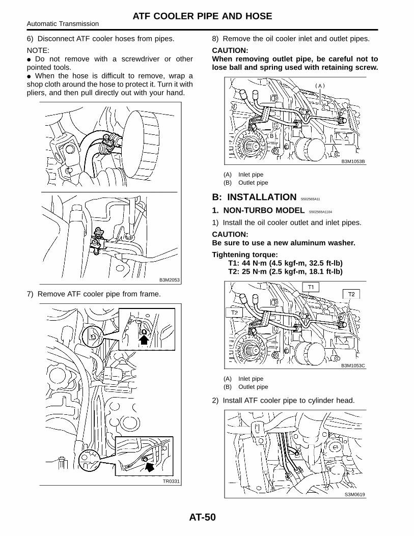
1) Set vehicle on a lift.2) Remove battery and washer tank.3) Lift vehicle.4) Remove the under cover.5) Disconnect ATF cooler hose from radiator.
NOTE:� Do not remove with a screwdriver or otherpointed tools.� When the hose is difficult to remove, wrap ashop cloth around the hose to protect it. Turn it withpliers, and then pull directly out with your hand.
S2M0895
6) Disconnect ATF cooler hoses from pipes.
NOTE:� Do not remove with a screwdriver or otherpointed tools.� When the hose is difficult to remove, wrap ashop cloth around the hose to protect it. Turn it withpliers, and then pull directly out with your hand.
S2M0909
7) Remove ATF cooler pipe from cylinder head.
S3M0619
8) Remove the oil cooler inlet and outlet pipes.
CAUTION:When removing outlet pipe, be careful not tolose ball and spring used with retaining screw.
B3M1053B
(A) Inlet pipe(B) Outlet pipe
2. TURBO MODEL S502565A1805
1) Set vehicle on a lift.2) Remove battery and washer tank.3) Lift vehicle.4) Remove the under cover.5) Disconnect ATF cooler hose from radiator.
(1) Remove radiator. <Ref. to CO-25,REMOVAL, Radiator.>(2) Remove radiator under cover.(3) Remove ATF cooler hose from radiator.
AT-49
ATF COOLER PIPE AND HOSEAutomatic Transmission
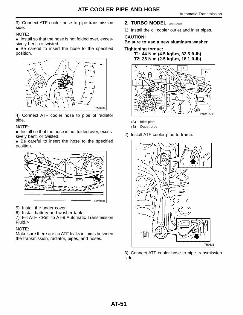
6) Disconnect ATF cooler hoses from pipes.
NOTE:� Do not remove with a screwdriver or otherpointed tools.� When the hose is difficult to remove, wrap ashop cloth around the hose to protect it. Turn it withpliers, and then pull directly out with your hand.
B3M2053
7) Remove ATF cooler pipe from frame.
TR0331
8) Remove the oil cooler inlet and outlet pipes.
CAUTION:When removing outlet pipe, be careful not tolose ball and spring used with retaining screw.
B3M1053B
(A) Inlet pipe(B) Outlet pipe
B: INSTALLATION S502565A11
1. NON-TURBO MODEL S502565A1104
1) Install the oil cooler outlet and inlet pipes.
CAUTION:Be sure to use a new aluminum washer.
Tightening torque:T1: 44 N·m (4.5 kgf-m, 32.5 ft-lb)T2: 25 N·m (2.5 kgf-m, 18.1 ft-lb)
B3M1053C
(A) Inlet pipe(B) Outlet pipe
2) Install ATF cooler pipe to cylinder head.
S3M0619
AT-50
ATF COOLER PIPE AND HOSEAutomatic Transmission
3) Connect ATF cooler hose to pipe transmissionside.
NOTE:� Install so that the hose is not folded over, exces-sively bent, or twisted.� Be careful to insert the hose to the specifiedposition.
S2M0909
4) Connect ATF cooler hose to pipe of radiatorside.
NOTE:� Install so that the hose is not folded over, exces-sively bent, or twisted.� Be careful to insert the hose to the specifiedposition.
S2M0895
5) Install the under cover.6) Install battery and washer tank.7) Fill ATF. <Ref. to AT-9 Automatic TransmissionFluid.>
NOTE:Make sure there are no ATF leaks in joints betweenthe transmission, radiator, pipes, and hoses.
2. TURBO MODEL S502565A1105
1) Install the oil cooler outlet and inlet pipes.
CAUTION:Be sure to use a new aluminum washer.
Tightening torque:T1: 44 N·m (4.5 kgf-m, 32.5 ft-lb)T2: 25 N·m (2.5 kgf-m, 18.1 ft-lb)
B3M1053C
(A) Inlet pipe(B) Outlet pipe
2) Install ATF cooler pipe to frame.
TR0331
3) Connect ATF cooler hose to pipe transmissionside.
AT-51
ATF COOLER PIPE AND HOSEAutomatic Transmission

NOTE:� Install so that the hose is not folded over, exces-sively bent, or twisted.� Be careful to insert the hose to the specifiedposition.
S2M0909
4) Connect ATF cooler hose to pipe of radiatorside.
(1) Install ATF cooler hoses to radiator.(2) Install radiator under cover.(3) Install radiator. <Ref. to CO-27,INSTALLATION, Radiator.>
5) Install the under cover.6) Install battery and washer tank.7) Fill ATF. <Ref. to AT-9 Automatic TransmissionFluid.>
NOTE:Make sure there are no ATF leaks in joints betweenthe transmission, radiator, pipes, and hoses.
AT-52
ATF COOLER PIPE AND HOSEAutomatic Transmission
C: INSPECTION S502565A10
Repair or replace any defective hoses, pipes,clamps, and washers found from the inspectionbelow.1) Check for ATF leaks in joints between thetransmission, radiator, pipes, and hoses.2) Check for deformed clamps.3) Lightly bend the hose and check for cracks inthe surface and other damage.4) Pinch the hose with your fingers and check forpoor elasticity. Also check for poor elasticity in theparts where the clamp was by pressing with yourfingernail.5) Check for peeling, cracks, and deformation atthe tip of the hose.
AT-53
ATF COOLER PIPE AND HOSEAutomatic Transmission
MEMO:
AT-54
Automatic TransmissionATF COOLER PIPE AND HOSE