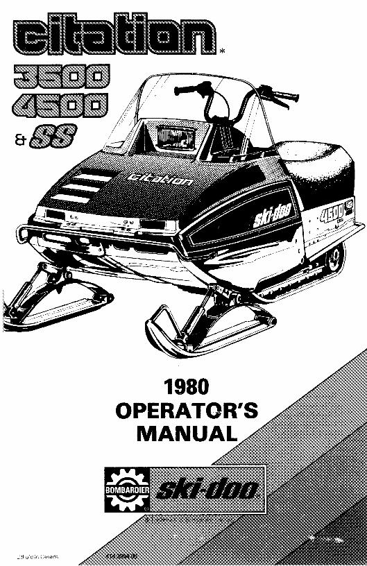
1980 operator's manual - vintage sno citation 1.pdf · 1980 operator's manual. model...
TRANSCRIPT
*
l.ithod in Canada
1980OPERATOR'S
MANUAL
model
V.I.N.
purchase date _
warranty expiry date
DEALER IMPRINT AREA
MOTO-SKIFUTURASPIRITNUVIKMIRAGESUPER SONICULTRA SONIC
TECHNICAL INFORMATION CENTREAFTER SALES SERVICE DEPARTMENTBOMBARDIER LIMITEDVALCOURT, QUEBECCANADA, JOE2LO
The following are trademarks of Bombardier Limited.BOMBARDIER EVERESTSKI-DOO CITATIONALPINE OLYMPIQUEBLIZZARD T'NTCARRY-BOOSEELANELITEGRAND PRIX SPECIAL

INDEX
FOREWORD 2
SAFETY IN MAINTENANCE 3CONTROLS/INSTRUMENTSThrottle lever, brake lever, ignition light switch, headlamp dimmer switch, emergency cut-out switch, light switch, manual starter handle, primer, tether cut-outswitch, adjustable steering, speedometer (optional on some models), hood open-ing, tool box, fuel gauge 4
BREAK-IN PERIODBreak-in, inspection, inspection checklist 8
FUEL MIXINGRecommended gasoline, recommended oil, fuel mixture ratio, fuel mixing proce-dure, injection oil 8
PRE-START CHECKCheck points 10
STARTING PROCEDUREStarting procedure, emergency starting 10
LUBRICATIONFrequency, drive pulley, pulley guard removal, drive belt removal, steeringmechanism, chaincase oil level, slide suspension 12
MAINTENANCEMaintenance chart, spark plugs, battery, suspension, track, track tension andalignment, carburetor adjustment, drive belt, steering mechanism, drive pulley,brake, steering adjustment, engine head nuts, engine mount nuts, mufflerattachment, fan belt, general inspection, headlamp beam aiming, oil injectionpump, bulb replacement 15
STORAGETrack, suspension, ski assembly, controls, chaincase, drive pulley, fuel tank, car-buretor, cylinder lubrication, battery, chassis, general inspection 22
PRE-SEASON PREPARATIONPre-season preparation chart 28
TROUBLE SHOOTING 27TOOLING 29SPECIFICATIONS 30WIRING DIAGRAMS 32S.I. METRIC INFORMATION GUIDE 35THE 1980 "UMITED WARRANTY" 38OFTEN ASKED QUESTIONS 40HOW TO IDENTIFY YOUR SNOWMOBILE 42CHANGE OF ADDRESS OR OWNERSHIP 43LISTING OF AREA DISTRIBUTORS 45
FOREWORD
CONGRATULATIONS ... You are nowthe proud owner of a new 1980 Bombardier snowmobile. This vehicle is theresult of incomparable teamwork between Bombardier designers, engineers and technicians. Consequently,this vehicle is designed and engineeredwith safety, handling, comfort andquietness in mind.The Operator Manual and the Snowmobile Safety handbook have beenprepared to acquaint the owner / operator of a new snowmobile with the various vehicle controls maintenance andsafe operating instructions.Each is indispensable for the properuse of the product, and should be keptwith the vehicle at all times.
Should you have any questions pertaining to the warranty and its application, please consult the "Often AskedQuestion" section of this manual, oryour selling dealer.
This manual emphasizes particular information denoted by the followingsymbols and wording.
+WARNING: Identifies an instruction which, if not followed, could
cause personal injury.
... CAUTION: Denotes an instruc... tion which, if not followed, could
severely damage vehicle components.
O NOTE: Indicates supplementary. information needed to fully complete an instruction.
Although the mere reading of such information does not eliminate the hazard, your understanding of the information will promote its correct use.
Ride safe and have fun.
Recreational Products GroupBombardier Limited,Valcourt, Quebec, Canada, JOE 2LO
Most specifications are given in both metric and customary units. Where preciseaccuracy is not required, some conversions are ronded to even numbers foreasier use.
PLEASEENSURE YOUR WARRANTY BY REGISTERING YOURSNOWMOBILE THROUGH YOUR DEALER, AT THE COMPANY.
2

SAFETY IN MAINTENANCE
Observe the followingprecautions:• Throttle mechanism should be
checked for free movement beforestarting engine.
• Engine should be running only whenpulley guard is secured in place.
• Never run the engine without drivebelt installed. Running an unloadedengine can prove to be dangerous.
• Never run the engine when the trackis raised off the ground.
• It can be dangerous to run enginewith the cab removed.
• Gasoline is flammable and explosiveunder certain conditions. Alwaysperform procedures in a well ventilated area. Do not smoke or allowopen flames or sparks in the vicinity.If gasoline fumes are noticed whiledriving, the cause should be determined and corrected without delay.
• Your snowmobile is not designed tobe operated on public streets, roador highways. In most States andProvinces, it is considered an illegaloperation.
• Maintain your vehicle in top mechanical condition at all times.
• Your snowmobile is not designed tobe driven or operated on black top,bare earth, or other abrasive surfaces. On such surfaces abnormaland excessive wear of critical partsis inevitable.
• Only perform procedures as detailedin this manual. Unless otherwisespecified, engine should be turnedOFF for all lubrication and maintenance procedures.
• Installation of other than standardequipment, including ski-spreaders,bumpers, pack racks, etc., couldseverely affect the stability and safety of your vehicle. Avoid adding onaccessories that alter the basic vehicle configuration.
• The snowmobile engine can bestopped by activating the emergency cut-out or tether switches or turning off the key.
• Whenever the vehicle is parked outdoors, overnight or for a longperiod, it is suggested to protect itagainst the inclemency of thewheather with a snowmobile cover.
Please read and understand all otherwarnings contained elsewhere.
This vehicle is built with parts dimensioned in the metric system. All fasteners aremetric and must not be replaced by customary fasteners. Mismatched or incorrect fasteners can cause damage to the vehicle or possible personal injury.
THIS MANUAL SHOULD REMAIN WITH THE VEHICLE ATTHE TIME OF RESALE.
3

CONTROLS/INSTRUMENTS
BA
1~~f1'::.:;;:J\-;;iiiiiiii~'\'·L~~ H
~~--G
AJ Throttle Control LeverBJ Brake Control LeverCJ Ignition/Light SwitchDJ Headlamp Dimmer SwitchEJ Emergency Cut-Out SwitchF) Light Switch (Electric Model)
A) Throttle Control LeverLocated on right side of handlebar.When compressed, it controls the engine speed and the engagement of thetransmission. When released, enginespeed returns automatically to idle.
B) Brake Control LeverLocated on the left side of handlebar.When compressed, the brake is applied. When released, it automaticallyreturns to its original position. Brakingeffect is proportionate to the pressureapplied on the lever.
C) Ignition/Light Switch
OFF
""ON
4
G) Manual Starter HandleH) PrimerI) Tether Cut-Out SwitchJ) Adjustable Steering HandleKJ Speedometer (Optional on Some
Models)
Key operated, 2 position switch. Tostart engine, first turn key clockwise toON position. To stop engine, turn keycou nter-clockwise to 0 FF position.
The lights are automatically ON whenever the engine is running.
(Electric Start Models)
OFF
"" ON
- START
Key operated, 3 POSItion switch. Tostart engine, turn key fully clockwise toSTART position and hold. Return keyto ON position immediately whenengine has started. To stop engine,turn key counter-clockwise to OFFposition.

D) Headlamp Dimmer SwitchThe dimmer switch, located on leftside of handlebar, allows correct selection of headlamp beam. To obtain highor low beam simply depress switch.
E) Emergency Cut-Out SwitchA push button switch located on rightside of handlebar. To stop the enginein an emergency I press button downinto lower position.
Before re-starting engine always depress button into released upper position. The driver of this vehicle shouldfamiliarize himself with the function ofthis device by using it several times onfirst outing, thereby being mentallyprepared for emergency situations requiring its use.
•WARNING: If the button hasbeen used in an emergency situa
tion the source of malfunction shouldbe determined and corrected before restarting engine.
Fl Ught Switch (Electric StartModels)A push pull switch type, to illuminateheadlamp and taillight, pull switchknob. Ognition switch must be turnedto 0 N position).
G) Manual Starter HandleAuto rewind type located on right handside of vehicle. To engage mechanism,pull handle.
H) PrimerA push-pull button. Pull and push button (2-3 times) to activate primer. Theprimer should always be used for coldengine starts. After engine is warmhowever, it is not necessary to useprimer when starting.
I) Tether Cut-Out SwitchAttach tether cord to wrist or otherconvenient location then snap tethercut-out cap over receptacle beforestarting engine.
If emergency engine "shut off" is required, completely pull cap from safetyswitch and engine power will be automatically shut 1I0 f f " .
O NOTE: The cap must be installedon the safety switch at all times in
order to operate the vehicle.
•WARNING: If the switch is usedin an emergency situation the
source of malfunction should be determined and corrected before restartingengine.
J) Adjustable steering handle- Remove handle cap and loosen the
4 bolts.
Adjust the steering handle to the desired position.
Lock the steering handle in place bytightening the four (4) screws to 26N.m (19 ft-lbs).
•WARNtNG: Do not adjust thehandlebar to high to avoid inter
ference when turning, between thebrake lever and windshield.
K) SpeedometerThe speedometer is linked directly tothe drive axle. Direct-reading dial indicates the speed of the vehicle. Odometer records the total distance travelled.
Hood OpeningPull down the latches to unlock thehood from the anchor.
O NOTE: Always lift hood gently upuntil stopped by restraining de
vice .
•WARNING: It isdangerous to runan engine with the hood open or
removed. Personal injury could result.
5

Tool BoxLocated under the cab. To gain access,tilt cab. Ideal location for spare plugs,belt, rope, etc.
Fuel GaugeUnscrew fuel tank cap and withdrawdipstick to check fuel level.
.... WARNING: Never use a lit match
.... or open-flame to check fuel level.
6
BREAK..IN PERIOD
With Bombardier-Rotax snowmobileengines, a break-in period is requiredbefore running the vehicle at full throttle. Engine manufacturer recommendation is10to 15 operating hours. During this period, a richer mixture isneeded (i.e. 40 parts of gas for 1 part of50/1 Bombardier oil). Maximum throttle should not exceed 3/4, however,brief full acceleration and speed variations contribute to a good break-in.Continued wide open throttle accelerations, prolonged cruising speeds, andlugging are detrimental during thebreak-in period.
Oil Injection ModelsOil injection models do not require mixing oil with gas. However, properbreak-in period applies.
1D-Hour InspectionAs with any precision piece of mechanical equipement, we suggest that afterthe first 10 hours of operation or 30days after the purchase, whichevercomes first, that your vehicle be checked by your dealer. This inspection willgive you the opportunity to discuss theunanswered questions you may haveencountered during the first hours ofoperation. Remember that it is easierto remedy at this time than to allow thesnowmobile to operate until a possiblefailure occurs.
The 10 hours inspection is at the expense of the vehicle owner.

1G-HOUR INSPECTION CHECK LIST IEngine timing
Fan belt tension
Spark plug(s} condition: (Remove and clean)
Carburetor adjustment
Oil injection pump adjustment.
Engine head nuts
Engine mount nuts
Muffler attachment
Chaincase and injection system oil levels
Brake operation and lining condition
Ski alignment (runner condition)
Pulley alignment and drive belt condition
Track condition, tension and alignment
Lubrication (steering) --JElectrical wiring (loose connections, stripped wires, damaged insulation), tighten all loosebolts, nuts and linkage
Operation of lighting system (HI / LO beam, brake tight, etc.), test operation of emergencycut-out switch and tether cut-out switch
We recommend. that you have your dealer sign this inspection .
Date of 10 hour inspection Dealer signature
7

FUEL MIXING
On models not equipped with oil injection, oil must be added to the gasolinein pre-measured amounts then both oiland gasoline should be throughly mixed together before fueling the tank.
Recommended GasolineUse regular leaded gasoline availablefrom all service stations.... CAUTION: Never experiment• with different fuel or fuel ratios.
Never use naphtha, methanol or similarproducts,
Recommended OilUse concentrated Bombardier snowmobile oil available from your dealer.This type of oil has specially formulated oil bases to meet the lubricationrequirements of the Bombardier-Rotaxengine.
If Bombardier snowmobile oil is unavailabe, substitute with a high-quality2 cycle snowmobile oil. The oil/gasmix must meet the vehicle requirements. See oil manufacturer recommendations on container.
~ CAUTION: Never use outboard• or straight mineral oils.
Fuel Mixture RatioThe importance of using the correctfuel mixture cannot be overstressed.An incorrect fuel ratio results in seriousengine damage. Recommended fuelratio is 50/1 .S.1. MEASURE
500 mL oil to 25 liters 50/1IMPERIAL MEASURE
1 can 16 02 oil to 5 imp. gals 50/1or1 can 500 mL to 51/2 imp. gals 50/1U.S. MEASURE
1 can 12 oz oil to 5 U.S. gals 50/1
.0 NOTE: To facilitate fuel rnixinq,oil should be kept at room tem
perature.
8
Fuel Mixing ProcedureTo mix the gasoline and oil always usea separate clean container. Never mixdirectly in your snowmobile tank. Forbest results, acquire two containers.either plastic or metal. Draw from oneuntil empty then use the second one.
....WARNING: Gasoline is flamma
..... ble and explosive under certainconditions. Always perform procedures in a well ventilated area. Do notsmoke or allow open flames or sparksin the vicinity. If gasoline fumes arenoticed while driving, the cause shouldbe determinetd and corrected withoutdelay. Never add fuel while engine isrunning. Avoid skin contact with fuelat below freezing temperatures.
1. Pour approximately one gallon ofgasoline into a clean container.
2. Add the full amount of oil.

3. Replace container cap and shake Check level and refill every time you re-the container thoroughly. fuel.
4. Add the remainder of the gasoline.
5. Once again thoroughly agitate thecontainer. Then using a funnel witha fine mesh screen to prevent theentry of water and foreign particles,transfer mixture from container intothe snowmobile tank.
a NOTE: When using pre-mixedfuel, always shake the container
thoroughly as the oil has a tendency tosettle.
+W ARNING: Never 'top up' gastank before placing the vehicle in
a warm area. At certain temperatures,gasoline will expand and overflow.
Oil Injection ModelsAlways maintain a sufficient amount ofBombardier 50 to 1 snowmobile oil inthe injection system oil tank.
9

PRE-START CHECK STARTING PROCEDURE
Check Points• Activate the throttle control lever
several times to check that it operates easily and smoothly. The throttle control lever must return to idleposition when released.
• Check fuel level.• Check injection oil level (if appli
cable).
• Check that the skis and the track arenot frozen to the ground or snowsurface and that steering operatesfreely.
• Activate the brake control lever andmake sure the brake fully applies before the brake control lever touchesthe handlebar grip.
• Verify that the path ahead of the vehicle is clear of bystanders and obstacles.
.& WARNING: Only start your
.... snowmobile once all componentsare checked and functioning properly.
10
Emergency Cut-Out Button
Upper position Low. positionbefore starting engine to stop engine
Manual Starting1. Insert the key in the ignition switch
and turn to ON position.2. Test throttle control lever.
3. Activate the primer (2 or 3 times).
O NOTE: The use of the primer isnot necessary when the en
gine is warm.
4. Make sure that the tether cut-outcap is in position and that the cord isattached to your clothing. Checkthat the emergency cut-out buttonis in the released upper position.
5. Grasp manual starter handle firmlyand pull slowly until a resistance isfelt then pull vigorously. Slowly release the rewind starter handle.
.& WARNING: Do not apply throttle
.... while starting.
6. Check the operation of the emergency cut-out switch and the tetherswitch. Restart the engine.
.& WARNING: If engine does not
.... shut-off when applying the emergency cut-out switch and pulling thetether cut-out cap, stop the engine byturning off the ignition key. Do notoperate the vehicle further1 see yourdealer.
7. Allow the engine to warm beforeoperating at full throttle.

Electric Starting... CAUTION: Never operate your.. snowmobile with the battery re
moved or disconnected.
1. Insert key in ignition switch.
2. Test throttle control lever. Activateprimer (2 or 3 times).
O NOTE: Primer is not necessarywhen engine is warm.
3. Make sure that the tether cut-outcap is in position and that the cord isattached to your clothing. Checkthat the emergency cut-out buttonis in the released upper position.
4. Turn ignition key clockwise untilstarter engages. If engine does notstart on first try, key must be turnedfully back to OFF each time .
...... WARNING: Do not apply throttle
... while starting.
5. Released key immediately after engine has started.
6. Check operation of the emergencycut-out switch and tether switch.Restart engine.
.&. WARNING: If engine does not
... shut-off when applying the mergency cut-out switch and pulling thetether cut-out cap, stop the engine byturning off the ignition key. Do notoperate the vehicle further, see yourdealer.
7. Allow the engine to warm beforeoperating at full throttle.
Emergency StartingSingle Carburetor Models(with roller round shaft pulley)Should the rewind starter rope fray andbreak, the engine can be started withan emergency starter rope and clip.
...... WARNING: Do not start the ve-
... hicle by the drive pulley unless itis a true emergency situation, have thevehicle repaired as soon as possible.
Remove the pulley guard from vehicle.Assemble the emergency starting clipto the emergency starting rope andwind the rope tightly around the drivepulley.
Start as per manual starting procedure .
...... WARNING: When starting theq ... vehicle in an emergency situation, by the drive pulley do not reinstall the• pulley guard.
11

Dual Carburetor Models(with roller square shaft pulley)Remove the pulley guard from the vehicle and wind the emergency ropetight around the drive pulley betweenthe sliding half and the roller guard.Start the engine as per usual manualstarting.
..... WARNING: When starting the
.... vehicle in an emergency situationby the drive pulley, do not make a knotat the end of the emergency rope anddo not reinstall the pulley guard.
/
12
lUBRICATION
FrequencyRoutine maintenance is necessary forall mechanized products, and thesnowmobile is no exception. A weeklyvehicle inspection contributes to thelife span of the snowmobile as well asretains safe and dependable operation.It is recommended that the steeringsystem and suspension be lubricatedmonthly or every 40 hours of operation. If the vehicle is operated in wetsnow or in severe conditions theseitems should be lubricated more frequently...... WARNING: Only perform such.... procedures as detailed in thismanual. It is recommended that dealerassistance be periodically obtained onother components/systems not covered in this manual. Unless otherwisespecified, engine should be turned OFFfor all lubrication and maintenance procedures.
Drive Pulley (roller round shafttype single carburetor models)This drive pulley requires lubrication bimonthly or every 20 hours of operation .
..... WARNING: The lubrication of
.... the drive pulley should be performed only by an authorized dealer. Adisassembly, cleaning, inspection andlubrication where applicable shouldalso be performed by the dealer every50 operating hours or at the end ofeach season, whichever occurs first.IMPORTANT: The drive pulley assembly will be excluded from warranty, ifthe factory seal is broken by other thana duly authorized representative ofBombardier.

Pulley Guard Removal.... WARNING: Pulley guard shouu,.... always be in place when engine isrunning.
A. Raise the hood and pull up the frontretaining pin; pry the guard removalrearward and raise the guard.
B. Pull the guard out of the center retaining bolt.
C. Remove the retaining clip of the rearpin and remove the pin.
D. Remove the guard.
Drive belt removal and installation..... WARNING: At the removal or in.... stallation of the drive belt becareful not to burn yourself on the exhaust muffler.
1. Remove the pulley guard.
2. Loosen the countershaft bearing retaining screw and open the bearingcage.
3. Open the driven pulley by twistingand pushing the sliding half. Hold infully open position .
4. Slip the belt over the top edge of thesliding half.
5. Lift the countershaft upward approx. 50 mm (2 in.) and slip the beltbetween the shaft and the bearingcage to remove completely.
13

o
Cap plug
Filler ---...,,4it-il~"~plug
Chaincase Oil LevelCheck the oil level by removing the oillevel cap plug.
The oil should be level with the bottonof the oil level orifice.
O NOTE: The chaincase oil capacitis approximately 170 mL (6 oz.).
Steering Mechanism
•WARNING: Do not lubricatethrottle and/or brake cables and
housings.
Lubricate the ski legs at grease fittingsuntil new grease appears at joints. Oilspring coupler bolts .
Brake disc--+--+-M
Brake pads ~--tto-....
To install the drive belt, reverse theprocedure.
_ CAUTION: Once belt is installed,.... be sure to secure the counter
shaft bearing by closing the bearingcage and firmly tightening the retainingscrew.
Slip the belt out from the drive pulley.
•WARNING: It may necessary toloosen the brake adjustment in
order to easily lift the countershaft. Always check that the brake disc is correctly installed between the brake padsand that the brake is well adjusted.Check brake light operation.
Brake light --+--t---...switch
14

Grease fittings
MAINTENANCE
The following Maintenance Chart indcates regular servicing schedulesto beperformed by you or your servicingdealer. If these services are performedas suggested, your snowmobile willgive you many years of low-cost use.
.&. WARNING: Only perform such
... procedures as detailed in thismanual. It is recommended that dealerassistance be periodically obtain~ onother components/systems not coeredin this manual. Unless otherwisespecified, engine should be turned OFFfor all lubrication and maintenance procedures.
Code (Weekly) Ita!e
W1 Spark plug 15W2 Battery (electric start models) 16W3 Suspension condition 16W4 Track condition 16W5 Track tension and alignment 17W6 Carburetor adjustment 18W7 Drive belt 19W8 Steering mechanism 19W9 Drive pulley 19
Code (Monthly) ltatJe
Ml Brake 19M2 Steering adjustment 20M3 Engine head nuts 20M4 Engine mount nuts 20M5 Muffler attachment 20M6 Fan belt 20M7 General inspection 21
Headlamp adjustmentM8 Oil injection pump 21
(W1) Spark PlugsDisconnect the spark plug wires andremove the spark plugs.
Check the condition of the plugs.
• A brownish tip reflects ideal conditions. (Correct carburetor, sparkplug heat range; etc.).
• A black insulator tip indicates foulingcaused by: carburetor idle speedmixture and/or high speed mixturetoo rich, incorrect fuel mixture ratio,wrong type of spark plug (heatrange), or excessive idling.
15

• A light grey insulator tip indicates alean mixture caused by; carburetorhigh speed mixture adjusted toolean, wrong spark plug heat range,incorrect fuel mixture ratio, or aleaking seal or gasket.
•CAUTION: If spark plug condition is not ideal, contact your au
thorized dealer.Check spark plug gap using a wirefeeler gauge.
Reinstall plugs and connect wires.
(W4) Track ConditionLift the rear of the vehicle and supportit off the ground. With the engine off,rotate the track by hand, and inspectcondition. If worn, cut or track fibersare exposed or missing or defective inserts or guides are noted, contact yourdealer.
A WARNING: Do not operate a.... snowmobile with a cut, torn ordamaged track.
•CAUTION: Do not allow cleaningsolution to enter battery. It will
destroy the chemical properties of theelectrolyte.
After reconnecting battery coat batteryterminals and connectors with petroleum jelly to prevent corrosion. Checkthat battery is well secured and thatbattery overflow tube is not blocked orkinked.
A WARNING: Overflow tube must.... be free and open. A kinked orbend tube will restrict ventilation andcreate gas accumulation that could result in an explosion. Avoid skin contactwith electrolyte .
•CAUTION: Prior to charg~ng thebattery, always remove It from
the vehicle to prevent electrolyte spillage.
(W3) Suspension ConditionVisually inspect all suspension components including slider shoes, springs,wheels, etc ...
O NOTE: During normal driving,snow will act as a lubricant and
coolant for the slider shoes. Extensiveriding on ice or sanded snow, (not tomention dirt, asphalt, etc. never recommended) will create excessive heatbuild-up and cause premature slidershoe wear.
Fouled(black)
Overheated(light grey)
(W2) Battery (Electric StartModels)Check electrolyte level. Electrolyte level must be at upper level line on battery casing.
If necessary add distilled water. Battery connections must also be free ofcorrosion. If cleaning is necessary remove corrosion using a stiff brush thenclean with a solution of baking sodaand water. Rinse and dry well.
16

(WS) Track Tension andAlignmentThe suspension is adjustable, the frontadjustment for surface condition, therear for driver's weight.
When the front adjuster blocks are atthe lowest elevation more weight isdistributed on the skis. At the highestposition the weight is transferred to thetrack. The rear adjuster blocks shouldbe adjusted to suit the driver's preference.
Adjuster 'blocks
~ CAUTION: Always turn the left.. side adjuster blocks in a clock
wise direction, the right side blocks in acounter-clockwise direction. Left andright adjuster blocks of each adjustment must always be set at the sameelevation.
Lift the rear of vehicle and support witha mechanical stand. Allow the slide toextend normally. Check the gap 13 rnrn(1/2/1) between the slider shoe and thebottom inside of the track. If the tracktension is too loose, the track will havea tendency to thump.
13 mm (1Ii')
~ CAUTION: Too much tension'9" will result in power loss and ex
cessive stresses on suspension components.
If necessary to adjust. Loosen the rearidler wheel retaining screw and thenloosen or tighten the adjuster bolts located on the inner side of the rear idlerwheels. If correct tension is unattainable. Contact your dealer.
O NOTE: Track tension and alignment are inter-related. Do not ad
just one without the other.
Start the engine and accelerate slightlyso that track turns slowly. Check thatthe track is well centered; equaldistance on both sides between edgesof track guides and slider shoes.
..&.WARNING: Before checking
...track alignment, ensure that thetra-ck is free of all particles which couldbe thrown out while track is rotating.Keep hands, tools, feet and clothingclear of track. Ensure no-one is standing in close proximity to the vehicle.
17

To correct, stop the engine, loosen therear idler wheels retaining screws thenloosen the lock nuts and tighten theadjuster bolt on side where the slidershoe is the furthest to the track insertguides.Tighten lock nuts and recheck thealignment. Ensure to retighten the idlerwheel retaining screws.
(we) Carburetor Adjustment.. CAUTION: Never operate your• snowmobile with the air intake
silencer disconnected. Serious enginedamage will occur if this notice is disregarded.
A) Air Screw AdjustmentCompletely close the air screw (until aslight reseating resistance is felt) thenback off screw as specified.
18
BIThrottle Slide Adjustment
•WARNING: Ensure the engine isturned OFF I prior to the throttle
slide adjustment.
With the throttle cable adjuster jam nutunlocked, press the throttle leveragainst the handle grip.
By turning the cable adjuster, adjustthe carburetor slide cut away so that itis flush with the top of the carburetorbore.Tighten the cable adjuster jam nut.
Throttle.... cable
adjuster
•WARNING: It is important thatthe throttle slide adjustment be
performed to ensure proper functioning of throttle mechanism.
C) Idle Speed AdjustmentTurn the idle speed screw clockwiseuntil it contacts the throttle slide thencontinue turning two (2) additionalturns. This will provide a preliminaryidle speed setting. Start the engine andallow it to warm then adjust the idlespeed to 2000 R.P.M. by turning theidle speed screw clockwise or counterclockwise.
.. CAUTION: Do not attempt to set• the idle speed by using the air
screw. Severe engine damage can occur. If idle speed is unattainable contact your authorized dealer.

CW7) Drive BeltInspect the belt for cracks, fraying orabnormal wear (uneven wear, wear onone side, etc.) If abnormal wear is noted, probable cause is pulley misalignment. Contact your dealer.
Check the drive belt width, if less than3 em (1 3/16") replace.
O NOTE: When installing a newdrive belt, a break-in period of 15
25 km (10-15 miles) is strongly recommended.
(WI) Steering MechanismInspect the steering mechanism fortightness of components (steeringarms, tie rods, ball joints, springcoupler bolts, etc.). If necessary, replace or retighten.
Check the condition of the skis and theski runners. Replace if worn.
(WI) Drive Pulley.(roller squareshaft type, dual carburetormodels only)Inspect the Duralon bushing conditionby checking the free-play of the slidinghalf pulley. This is achieved by restraining the inner half and checking if thesliding half moves in the direction ofthe arrows more than 3 mm (118"). Ifso contact your dealer.
Mark referencepoint
on both halves
Maximum free-play3 mm 11Is")
Drive Pulley (roller roundshaft type, single carburetormodels)This drive pulley requires lubrication bimonthly or every 20 hours of operation.
..... WARNING: The lubrication of
.... the drive pulley should be performed only by an authorized dealer. Adisassembly, cleaning, inspection andlubrication where applicable shouldalso be performed by the dealer every50 operating hours or at the end ofeach season, whichever occurs first.
IMPORTANT: The drive pulley assembly will be excluded from warranty, ifthe factory seal is broken by other thana duly authorized representative ofBombardier.
(M1) BrakeThe brake mechanism on your snowmobile is an essential safety device.Keep this mechanism in proper working condition. Above all, do not operate your snowmobile without an effective brake system.
..... WARNING: Brake pucks less
.... than 3 mm (1/8") thick must bereplaced. Replacement must be performed by an authorized dealer.
Brake should apply fully while brakecontrol lever is still 13 mm (1/2") approximative from the handlebar grip.
If adjustment is required, turn thebrake cable adjuster counter-clockwiseuntil the brake disc is hard to turn thenback off the adjuster to approximately1 1/2 turn. Recheck brake operation.
~111 ~;-
Brake cable Iadjuster
11111\\
19

... WARNING: Whenever the brake~ is readjusted, the brake lightswitch operation mustalso be checkedand adjusted as needed.
1M2) Steering AdjustmentSkis should have a toe out of 3 mm(1/8"). To check, measure the distancebetween each ski at the front and rear ofthe leaf springs. The front distanceshould be 3 mm (1/8") more than therear when the handlebar is horizontal.
IMPORTANT: Closethe front of the skismanually to eliminate all slack from thesteering mechanism.If adjustment is required:Loosen the lock nuts of the longer tierod. Turn the tie red manually until theskis are properly aligned. Firmlyretighten the lock nuts.
3 mm (118")toe out
The handlebar should also be horizontalwhen the skis are pointed toward thefront.
To adjust:Loosen the lock nuts of the shorter tierod. Turn the tie rod manually until thehandlebar is horizontal. Retighten thelock nuts firmly .
•WARNING: The ball joint socketmust run parallel with the steer
ingarm. The socket mustbe restrainedwhen tightening thetierod end lock nuts.
20
(M3) Engine Head NutsWith the engine cold, check that theengine head nuts are tight and equallytorqued to 22 N-m (16 ft-lbsl.
IMPORTANT:The engine head nut torque should be checked after the first 5hours of operation.
(M4) Engine Mount NutsCheck the engine mount nuts for tightness. Retighten if necessary.
(M5) Muffler AttachmentThe engine/muffler attaching parts arevital toward efficient muffler function.Check all attachments. Replace thesprings and/or tighten if necessary.
(MI) Fan BeltInspect belt for cracks, uneven wear,etc. Check fan belt tension, 6 mm (1/4")free-play should exist when deflection iscorrect.

Headlamp Beam AimingThe angle of the headlamp beam hasbeen pre-adjusted prior to delivery.Should you wish re-adjustment, placethe vehicle on a flat surface 7.6 m (25')from a wall or screen.
if belt seems damaged or if tension is incorrect, contact your dealer immediately.
,.&. WARNING: If fan protector is reT moved, always reinstall after servicing.
Marks must align
(MS) Oil Injection PumpAdjustment... CAUTION: The carburetor must... be adjusted before adjusting the
oil injection pump. Make sure the idlespeed is 2000 RPM.
To adjust: With engine stopped, eliminate the throttle cable free-play bypressing the throttle lever until a lightresistance is felt then hold in place.The aligning marks on the pumpcasting and lever must align perfectly.If not, loosen the adjuster nut and adjust accordingly.
Tighten the adjuster nut.
O NOTE: The oil injection pumpsynchronizing marks can be seen
by placing a mirror between the sideIpan and the pump.
To adjust, remove headlamp chromering, turn upper or lower adjustingscrews to obtain desired beam position.
lGround
TOPVIEW
SIDE VIEW
(M7) General InspectionCheck the electrical wiring and components, retighten loose connections.Check for stripped wires or damaged insulation. Thoroughly inspect the vehicleand tighten loose bolts, nuts andlinkage. Inspect skis and ski runners forwear.
With the suspension correctly adjusted,the rider seated on the vehicle and thehigh beam ON check that the center ofhigh intensity zone of high beam is 50mm (2") below horizontal line ofheadlamp height.
Headlamphorizontalcenter line
Center lineintensity zone
Intensity zoneof high beam(projected on
the wall)
50mm
... CAUTION: Proper oil injection... pump adjustment is very Im
portant. Any delay in the opening ofthe pump can result in serious enginedamage.
Adjustercable
21

Bulb ReplacementIf the headlamp bulb is burnt, tilt cab,unplug the connector from the headlamp. Remove the rubber boot and unfasten bulb retainer clips. Detach thebulb and replace. If taillight bulb isburnt, expose the bulb by removingthe red plastic lens. To remove, unscrew the two (2) Phillips head screws.Verify all lights after replacement.
22
STORAGE
It is during summer, or when ~ vehicleis not in use for any length of time thatproper storage is a necessity. Stor~ge
of the snowmobile dunng long periodof inactivity consists of checking andreplacing missing, broken or wornparts, proper lubrication and treatmentto insure that parts do not becomerusted; cleaning items such as carburetor of oil mixtures, to prevent gumvarnish formation within the carburetor; and in general, preparing the vehicle so that when the time comes to usethe snowmobile again it will start andbe in top condition .
.... WARNING: Only perform such
... procedures as detailed in thismanual. It is recommended that dealerassistance be periodically obtained onother components/systems not covered in this manual. Unless otherwisespecified, engine should be turned OFFfor all lubrication and maintenance procedures.
TrackInspect the track for wear, cuts, missing track guides and broken rodsMake any necessary replacement .
.... WARNING: Do not operate •
... snowmobile with a cut, torn 0damage track.
Lift the rear of vehicle until track iclear of the ground then support with,brace or trestle. The snowmobilshould be stored in such a way that thtrack does not stay in contact with thcement floor or bare ground.
O NOTE: The track should be rota'ed periodically, (every 40 days
Do not release track tension .
... CAUTION: To prevent trac... damage, temperature in the sto
age area must not exceed38°C (100°F
Slide SuspensionRemove any dirt or rust. Grease idlwheels at grease fittings. Wipe off SL.plus. Replace worn slider shoes.

SkiWash or brush all dirt or rust accumulation from the skis and springs.Grease the ski legs at the grease fittings. Check the condition of the skis,ski runners and leaf springs. Replace ifworn or weak.
ControlsLubricate the steering mechanism. Inspect all components for tightness,(spring coupler bolts, steering armlocking bolts, tie rods, ball joints, etc.l,Tighten if necessary. Oil moving jointsof the brake mechanism.• WARNING: Do not lubricate the~ throttle and/or brake cables andhousings. Avoid getting oil on thebrake pads.
Coat all electrical connections andswitches with a greaseless metal protector. If unavailable, use petroleumjelly.
ChaincaseDrain the chaincase and refill to properlevel, using fresh chaincase oil. Todrain, remove the chaincase cover.
Drive PulleyThe drive pulley should be cleaned andinspected. The roller round shaft typedrive pulley requires lubrication.
•WARNING: The lubrication of thedrive pulley should be per
formed only by an authorized dealer. Adisassembly, cleaning, inspection andlubricationwhere applicableshould alsobe performed by the dealer every 50operating hours or at the end of of eachseason, which ever occurs first.
IMPORTANT: The drive pulley assembly will be excluded from warranty, ifthe factory seal is broken by other thana duly authorized representative ofBombardier.
Fuel TankRemove the cap then using a syphon,remove the gasoline from tank .
•WARNING: Gasoline is flammable and explosive under certain
conditions. Always perform proceduresin a well ventilated area. Do not smokeor aHow open flames or sparks in thevicinity.
CarburetorCarburetor must be dried out completely to prevent gum formation duringthe storage period.
Once the fuel tank is emptied, removethe float chamber drain plug on eachcarburetor. Drain carburetor.
Re-install plug and connect fuel line.
Cylinder LubricationEngineinternal parts must be lubricatedto protect cylinder walls from possiblerust formation during the storageperiod.
O NOTE: This operation should berepeated every 40 days during
storage.
23

Remove the spark plugs. Operate therewind starter to bring the piston at topposition. Pour the equivalent of onespoonful of oil into spark plug hole.
Slowly crank the engine several timesusing the manual starter. Repeat abovesteps for other cylinder. Install the sparkplugs._ CAUTION: To prevent ignition..". system damage, make sure that
the cut-out button is in the lower position.
Battery Removal & Installation1. Remove and push aside the injec
tion oil reservoir. Do not disconnectthe hose.
2. Disconnect the battery cables andremove the battery cover.
3. Remove the battery vent tube fromthe vent hole.
4. Lift out the battery._ CAUTION: Be careful not to..". damage the oil injection pump
lever when lifting out the battery.
5. Reinstall by reversing the procedure.
24
BatteryRemove battery from vehicle and cleanoutside surface of battery with solutionof baking soda and water. Remove alldeposits from posts then rinse withclear tap water.
_ CAUTION: Do not allow cleaning.". solution to enter battery interior
since it will destroy the electrolyte.
Check electrolyte level. Refill if necessary with distilled water. Fully chargebattery. (A stored battery should be recharged at least every 40 days)._ CAUTION: Prior to charging the..". battery, always remove it from the
vehicle to prevent electrolyte spillage.
•WARNING: Gases given off by abattery being charged are highly
explosive. Always charge in a well ventilated area. Keep battery away fromcigarettes or open flames. Avoid skincontact with electrolyte.
Coat electrical connections andswithches with a greaseless metal protector, if unavailable, use petroleum jelly. Store unit in a cool, dry place.
ChassisClean the vehicle thoroughly, removingall dirt and grease accumulation._ CAUTION: Plastic alloy compo..". nents such as fuel tank, wind
shield, etc., can be cleaned using milddetergents or isopropyl alcohol. Do notuse strong soaps, degreasing solvents,abrasive cleaners, paint thinners, etc.
Inspect the cab and repair any damage. Repair kits are available at yourauthorized dealer. Clean the frame. Forthe aluminum portion use only"Aluminum cleaner" and follow instructionson the container.
Touch up all metal spots where painthas been scratched off. Spray all baremetal parts with metal protector. Waxthe cab for better protection.
O NOTE: Apply wax on glossy finishof cab only. Protect the vehicle
with a cover to prevent dust accumulation during storage.

.., CAUTION: If for some reason the... snowmobile has to be stored out
side it is necessary to cover it with anopaque tarpaulin. This caution will prevent the sun rays affecting the plasticcomponents and the vehicle finish.
General InspectionCheck the electrical wiring and components, retighten loose connections.Check for stripped wires or damagedinsulation.Thoroughly inspect the vehicle andtighten loose bolts, nuts and linkage.
O NOTE: Leave the drive belt offthe pulleys for the entire storage
period.
25

PRE-SEASON PREPARATION
Change spark plugs 0
Check chaincase oil level 0
Check pulleys, verify components and 0clean. Lubricate.
Check steering alignment and ski runner •condition
On vehicle equipped with fuel filter 0cartridge, replace cartridge.
Check track tension and alignment 0
Lubricate suspension 0
Inspect drive belt and install 0
Check throttle cable for damage 0and free operation
Inspect brake condition and operation •Inspect oil seals for possible cuts or leaks 0
Set engine timing, if necessary replace •breaker points
Check electrical wiring (broken wire, 0damaged insulation)
Inspect condition of starting rope 0
Check tightness of all bolts, nuts and 0linkage
Refill injection oil tank 0
Refill gas tank 0
Adjust carburetor •Adjust oil injection pump •
Snow is falling and you are now anticipating the next snowmobile safari. Ifyou have observed and adhered to thestorage procedures outlined in thismanual, your vehicle preparation becomes a relatively easy task.
To simplify the pre-season preparationwe have drawn up a small chart. Thechart indicates servicing points to beperformed by you and your servicingdealer. If these services are performedas suggested, your vehicle will giveyou many hours of fun and low costuse.IMPORTANT: Observe all Warningsand Cautions mentioned throughoutthis manual which are pertinent to theitem being checked. When componentconditions seem less than satisfactory,replace with genuine Bombardier partsor suitable equivalents.
26
PRE-SEASONPREPARATION CHART
To be performed by dealer
To be performed by owner
•o

TROUBLE SHOOTING
SYMPTOMS POSSIBLE CAUSES WHAT TO DO
Engine turns over but 1. No fuel to the engine Check the tank level and fill up with correctfails to start or starts gas-oil mixture. Check for possible clogging ofwith difficulty fuel line, item 5.
2. Flooded engine Remove wetspark plugs, turn ignition to OFFand crank engine several times. Install cleandry spark plugs. Stan engine following usualstaning procedure. If engine continues toflood, see your dealer.
3. Spark plug/faulty ignition Check for fouled or defective spark plug. Dis-connect spark plug wire, unscrew plug and re-move from cylinder head. Reconnect wire andground exposed plug on engine cowl, ...cnfuI to hold away frail spd plug .....Follow engine staning procedure and checkfor spark. If no sparks appear, replace sparkplug. If trouble persists, contact your dealer.
4. Clogged fuel line (water or Remove and clean the fuel filter. Change filterdirt) canridge if necessary. Check. condition and
connections offuel lines. Check the cleanlinessof fuel tank.
5. Faulty carburetor First make primary adjustments on carburetorISee Maintenance Sectionl. If carburetor isstill faulty, contact your dealer for repair.
6. Too much oil in fuel Drain the fuel tank and refill with the correctgasloil mixture.
7. Engine timing Engine timing may be defective or out of ad·justment. Contact your dealer.
8. Poor engine compression Running with a lean fuel mixture may produceexcessive engine wear resulting inpoor enginecompression. If this occurs, contact yourdealer at once.
-Engine will not turn 1. Seized engine In the case of a seized engine contact yourmanually dealer.
27
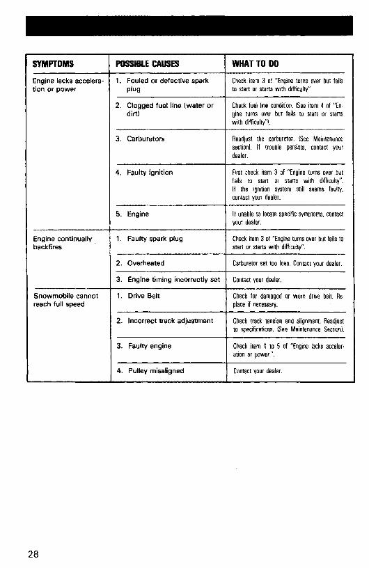
SYMPTOMS POSSIBLE CAUSES WHAT TO DO
Engine lacks accelera- 1. Fouled or defective spark Check item 3 of "Engine turns over but failstion or power plug to start or starts with difficulty"
2. Clogged fuel line (water or Check fuel line condition. ISee item 4 of "En-dirt) gine turns over but fails to start or starts
with difficulty"!'
3. Carburetors Readjust the carburetor. ISee Maintenancesection!. If trouble persists, contact yourdealer.
4. Faulty ignition First check item 3 of "Engine turns over butfails to start or starts with difficulty".If the ignition system still seems faulty,contact your dealer.
5. Engine If unable to locate specific symptoms, contactyour dealer.
Engine continually 1. Faulty spark plug Check item 3of "Engine turns over but fails tobackfires start or starts with difficulty",
2. Overheated Carburetor set too lean. Contact your dealer.
3. Engine timing incorrectly set Contact your dealer.
Snowmobile cannot 1. Drive Belt Check for damaged or worn drive belt. Re-reach full speed place if necessary.
2. Incorrect track adjustment Check track tension and alignment. Readjustto specifications. ISee Maintenance Section!.
3. Faulty engine I ;~:~ko;t·p~w~rt2. 5 of "Eng"" lacks aceeler-
4. Pulley misaligned Contact your dealer.
28

TOOLS
As standard equipment each newsnowmobile is supplied with a basictool kit such as screwdriver, wrenches,emergency starter rope, etc ...
Standard Tools
A
~===~-"""-'g
cE
o
A. Screwdriver
B. Socket 21/26 mm
C. Socket 10/13 mm
D. Socket handle
E. Angular wrench 10/13 mm
F. Starter rope
G. Emergency starting clip
~G
29

SPECIFICATIONS
CITATION 3500 CITATION 4500 CITATIONSSENGINENo. of cylinders 1 2 2Bore 72 mm (2.83") 62 mm (2.44") 62 mm (2.44")Stroke 66 mm (2.60") 61 mm (2.40") 61 mm (2.40")Displacement 268.7 cm3 (16.4 in3) 368.3 cm3 (22.47 in3) 368.3 cm3 (22.47 in3)Compression ratio 6.7:1 6.9:1 6.55:1(corrected)Carburetor type VM 34-228 VM 34-229 2 x VM 30-111Carburetor adjustment:
1 1/2 turn- air screw 1 turn- idle speed 1500-2000 RPM 2000 RPM 1500-2000
Engine head nuts (torque) 22 N.m (16 tt-lbs) 22 N.m (16 ft-Ibs) 22 N.m (16 ft-lbsl
CHASSISOverall length 249 cm (98") 263 cm (103 1/2") 249 cm (98")Overall width 92.7 cm (36 112") 92.7 cm (36 112") 92.7 cm (36 112")Overall height 98.4 cm (38 3/4") 98.4 cm (38 3/4") 98.4 cm (38 3/4")Ski stance 82 cm (321/4") 82 cm (32 1/4") 82 cm (32 1/4")(center to center)Ski alignment (toe out) 3.2 mm (1/8") 3.2 mm (1/8") 3.2 mm (1/8")Weight 148.3 kg (327 lbs) man: 160 kg (353 lbs) 159.7 kg (352 lbs)
elec: 172.4 kg (380 lbs)Bearing area 5838 cm2 (905 in2) 6225 cm2 (965 in2) 5838 cm2 (905 in2)Ground pressure 2.49 kPa L361 PSI) man: 2.52 kPa (,366 PSI) 2.68 kPa (.389 PSI)
elec: 2.72 kPa (.394 PSI)
POWER TRAINTrack dimensions 38.1 ern (15") 38.1 cm (15") 38.1 cm (15")
x 269.3 cm (106") x 289.6 cm (114") x 269.2 cm (106")Track tension 13 mm (1/2") gap should exist between slide shoe and bottom inside of
track.Track alignment Equal distance between edges of track guides and slider shoes.Std. gear ratio 15/34 16/33 18/34Chaincase oil capacity 170 mL (6 oz) 170 mL (6 oz) 170 mL (6 oz) .Drive belt 30.15 mm (13/16") 30.15 mm(l 3/16") 30.15 mm (1 3/16")
(minimum width)
ELECTRICALLighting system (output) 140 watts 140 watts 140 wattsHeadlamp bulb 45/45 W 45/45W 45/45 WTail stop/ light 5/21 W 5/21 W 5/21 WSpark plug (Bosch)
- normal use W275 T2 (W3C) W275 T2 (W3C) W275 T2 (W3C)- severe use
Spark plug (gap) .4 mm (.016") .4 mm L016") .4 mm (.016")Breaker points (gap) .35 mm (,014") .35 mm LOW') .35 mm LOW')Advance ignition timing 2.35 mm L092") 2.07 mm (.081") 2.07 mm L081")(B.T.D.C.)
FUELTank capacity - 5.1.* 28.4 liters 28.4 liters 28.4 liters
-Imp. 6.25 gals 6.25 gals 6.25 gals- U.S. 7.8 gals 7.8 gals 7.8 gals
Gasoline Regular Regular RegularInjection oil - 5.1.* NA 1.36 L NA
-Imp. NA 48 oz NA- U.S. NA 46 oz NA
N.A.: Not applicable
30

I CITATION 3500 I CITATION 4500 I CITATION SS
BRAKEBrake typeBrake adjustment(control lever)Brake lining I(minimum thickness)
Disc, adjust as required.13 mm (112") minimum distance from handlebar grip when fully applied.
3mm (118") 13 mm (118") 13 mm (118")
*International System
Bombardier Limited reserves the right to make changes in design and specifications and/or to make additions to, or improvements in its product without imposing any obligation upon itself to install them onits products previously manufactured.
31
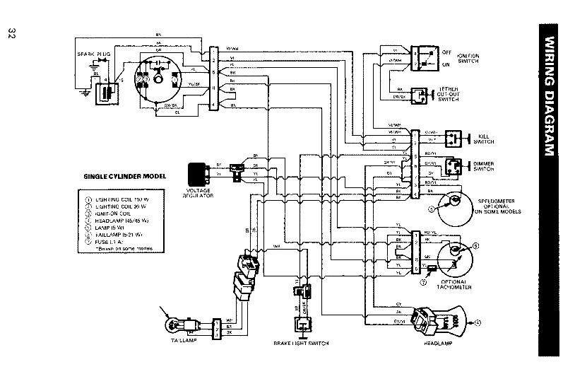
SPEEDOMETEROPTIONAL
ON SOME MODELS
@
OFF IGNITIONSWITCH
ON
TETHERCUT-OUTSWITCH
OPTIONALTACHOMETER
HEADLAMP
CD
GYIVI
BK
GY
YL
BK
YL
VI
VI
BK
VI/WH
VI/WH
GY
GY/VI
BRAKE LIGHT SWITCH
WH
BK
~t~
CD LIGHTING COIL 110 W
CD LIGHTING COIL 30 W
@ IGNITION COIL
o HEADLAMP (45/45 WI
® LAMP 15WI® TAILLAMP (5-21 WI
Q) FUSE1.1AI"Brown on some models
SINGLE CYLINDER MODEL
Wtv

OPTIONALSPEEDOMETER
DIMMERSWITCH
KILLSWITCH
HEADLAMP
G)
IGNITIONC;WITCH
,'--):-0...-0
BI(
GV
GN
aVIVl
RD
GV
--!!.e.ROIGN
~RO/Vl
'I'll GY
BI':
BRAKE LIGHT SWITCHTAILLAMP
®
GNRO
GN
LIGHTING COIL 110 W
LiGHTING COIL 30 WIGNITION GENERATOR COIL
Fuse 130 A.IFUSE (.1 AIFUSE 115A.)HEADLAMP 145145 WITAILLAMP 15-21 WI
LIGHT 15WIBATTERY 124A.ISTARTER
SOLENOiD SWITCHREGULATOR RECTIFIER"Brown on some models
ELECTRIC STARTMODEL
~@®®G)®
i@@
ww

SPEEDOMETEROPTIONAL
ON SOME MODELS
@
OPTIONALTACHOMETER
HEADLAMP
ElK
VI
GY
VI
BK
Yl
BK
GY/Vl
GY
VI/WH
VI/WH
GY/Vl
BRAKE LIGHT SWITCH
BK
'"<l)
VOLTAGEREGULATOR
TAILLAMP
®
COIL 110 W
COIL 30 WIGNITION COIL
HEADLAMP (45/45 WI
LAMP 15WI
TAILLAMP 15·21 WI
FUSE (.1 AI• Brown on some models
TWINCYLINDER MANUALSTART MODEL
W.f:!o

5.1.* METRIC INFORMATION GUIDE
BASE UNITS
DESCRIPTION
lengthmassliquidtemperaturepressuretorquespeed
PREFIX
kilocentimilli
SYMBOL
kcm
UNIT
meterkilogramlitercelsiuskilopascalNewton meterkilometer per hour
PREFIXES
MEANING
one thousandone hundredth of aone thousandth of a
SYMBOL
mkg
L°C
kPaN.m
km/h
VALUE
1,0000.010'.001
*THE INTERNATIONAL SYSTEM OF UNITS (SYSTEME INTERNATIONAL)ABREVIATES "SI" IN ALL LANGUAGES.
35
LIMITED WARRANTY SKI-DOOR SNOWMOBILES 1980
BOMBARDIER Limited as manufacturer, warrants FROM THEDATE OF FIRST CONSUMER SALE, every 1980 Ski-Doo® snowmobile, sold as NEW AND UNUSED, by an authorized SKI-DOOdealer, subject to the following limitations and conditions, for aperiod of:
• two (2) seasons maximum for models:Elan® , Citation*, Everest® , Elite® ,
Warranty STARTS on the date of sale to the first consumer andI:NDS the SECOND APRIL 30TH following the date warrantycoverage started.
or
• Ninety (90) consecutive days for the following models:BLIZZARD® 5500-7500-9500 and ALPINE® subject to the following:
1. When a sale is made after MARCH 31 ST of a given year butbefore THE 1ST DAY OF DECEMBER of the same year, the warranty will start on DECEMBER 1ST following the date of sale andterminate 90 days later.
2. When a sale is made on/or after JANUARY 2ND of a given year,the unused portion of the 90 days warranty as of MARCH 31ST,of that year will be carried over to the next season, beginning the1ST DAY OF DECEMBER.
Any 1980 model not listed is not warranted.
WHAT WE WILL DO
BOMBARDIER will repair and/or replace, at its option, componentsdefective in material and/or workmanship (under normal use andservice,) with a genuine BOMBARDIER component without chargefor parts or labour at any authorized SKI-DOD dealer during saidwarranty period.
36

EXCLUSIONS
Items and components:Any of the following expendable items and/or components that aredamaged or worn due to normal use: variable speed drive belt, windshield, filters, ignition breaker points, condensers, spark plugs, lightbulbs, protective lenses, brake linings, ski runner shoes, slider shoeson suspension and variable speed pulleys, labels, soft trim, appearance items, lubricants and paints and all tune-ups, seized,melted or holed piston and adjustments required.
Also excluded are:• Damage resulting from installation of parts other than genuine
BOMBARDIER parts.
• Damage caused by failure to provide proper maintenance asdetailed in the Operator Manual supplied with each SKI-DOOsnowmobile. The labour, parts and lubricants cost of allmaintenance services, including tune-ups and adjustments willbe charged to the owner.
• Damage resulting from improper servicing or adjustment of thedrive pulley assembly. The drive pulley assembly is factorysealed, and can only be serviced by an authorized SKI-DOOdealer.
• Vehicles used for racing purposes.• Vehicle used for rental purpose or other business purposes.
• All optional accessories installed on the vehicle.(The normal warranty policy for parts and accessories, if any,applies).
• Damage resulting from operation of the snowmobile on surfacesother than snow.
• Damage resulting from accident, fire or other casualty, misuse,abuse or neglect.
• Damage resulting from modification to the snowmobile not approved in writing by BOMBARDIER.
• Losses incurred by the snowmobile owner other than parts andlabour, such as, but not limited to, transportation, towing,telephone calls, taxis, or any other incidental or consequentialdamages.
37

Some states or provinces do not allow the exclusion or limitation ofincidental or consequential damages, so the above limitation or exclusion may not apply.
CONDITION TO HAVE WARRANTY WORK PERFORMEDPresent, to the servicing dealer, the hard copy of the BOMBARDIERCustomer Registration card given by the selling dealer at time of purchase.
EXPRESSED OR IMPLIED WARRANTIE~
This warranty gives you specific rights, and you may also have otherlegal rights which may vary from state to state, or province to province.
Where applicable this warranty is expressly in lieu of all other expressed or implied warranties of BOMBARDIER, its distributors andthe selling dealer, including any warranty of merchantability offitness for any particular purpose; otherwise the implied warranty islimited to the duration of this warranty. However, some states orprovinces do not allow limitations on how long an implied warrantylasts, so the above limitation may not apply.
Neither the distributor, the selling dealer, nor any other person hasbeen authorized to make any affirmation, representation or warrantyother than those contained in this warranty, and if made, such affirmation, representation or warranty shall not be enforceable againstBOMBARDIER or any other person.
CONSUMER ASSISTANCE
If a servicing problem or other difficulty occurs, we suggest thefollowing:
1. Try to resolve the problem at the dealership with the ServiceManager or Owner.
2. If this fails, contact your area distributor listed in the OperatorManual.
3. Then if your grievance still remains unsolved, you may write tous:Bombardier LimitedCustomer Relations DepartmentRecreational Product GroupValcourt, Quebec, Canada, JOE 2LO
38

Bombardier Limited reserves the right to modify its warrantypolicy at any time, being understood that such modification willnot alter the warranty conditions applicable to vehicles soldwhile the-above warranty is in effect.November 1978
Bombardier LimitedValcourt, Quebec, Canada, JOE 2LO
"Trademark of Bombardier Limited
® Registered Trademark Bombardier Limited
39

OFTEN ASKED QUESTIONS
Q: Why must my snowmobile be registered? After all I do have my original invoiceas proof of when I purchased my snowmobile.
A: The information provided by the Customer Warranty Registration card iscomputerized, and al/ warranty claims thereafter, are processed by the computer. Without this valuable information on the Warranty Registration Card,we cannot acknowledge warranty or notify owners ofa possible safety recall.
Q: How do I know my vehicle has been registered at the factory?
A: When you bought your snowmobile the dealer should have completed, andforwarded us the manufacturer's copy of the Customer Warranty Registration. The hardcopyof the card is yourproof that the snowmobile is registered.
Q: I bought my snowmobile in O'King County but I snowmobile in WashingtonCounty. Can the dealer in Washington County accept warranty work on mysnowmobile?
A: Yes, any authorized dealer in North America can perform warranty repairs,providing the customer warranty registration card is presented.
Q: Where can I find information on the lubrication and maintenance of my snowmobile?
A: In this Operator Manual provided with the vehicle at the time of first sale.
Q: Will the entire warranty be void or cancelled, if I do not operate or maintain mynew snowmobile exactly as specified in the Operator's Manual?
A: The warranty of the new snowmobile cannot be "voided" or "Cancelled".However, if a particular failure is caused by operation or maintenance otherthan is shown in the Operator Manual, that failure may not be covered underwarranty. This includes service work performed by the customer, especiallythe critical adjustments to ignition, timing, cerburetion and oil injection/or oilmixture.
Q: Would you give some examples of abnormal use or strain, neglect or abuse?
A: These terms are general and overlap each other in areas. Some specific examples may include: running the machine out of oil, sustained high r.p.m. fullthrottle use, chain failure caused by a lack of lubrication and/or adjustments,operating the machine with a broken or damaged part which causes anotherpart to fail, and so on. If you have any specific questions on operation or maintenance, please contact your dealer for advice.
40

0: What costs are my responsibility during the warranty period?
A: The customer's responsibility includes all costs ofnormal maintenance services, non-warranty repairs, accidents- and collision damage, as well as oils,and spark plugs, and incidental or consequential damages costs as explainedin the warranty. .
0: Are "Genuine" Bombardier replacement parts used in warranty repairs coveredby warranty?
A: Yes. When installed by an authorized dealer, any "genuine" Bombardierpart used in warranty repairs assumes the remaining warranty that exists onthe machine.
0: What is Bombardier's policy on extending a warranty?
A: It is not Bombardier's policy to extend warranty. Bombardier has selected awarranty period sufficiently long to permit adequate use of the machine toallow for possible concealed manufacturing defects to occur.
Q: If I sell my snowmobile within the warranty period, will the new owner qualifyfor the balance of the warranty?
A: Yes, provided the unit has already been registered with the manufacturer.Note that the change of ownership card in this manual should be completedand sent to Valcourt.
41
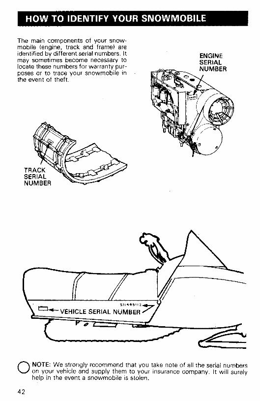
HOW TO IDENTIFY YOUR SNOWMOBILE
ENGINESERIALNUMBER
The main components of your snowmobile (engine, track and frame) areidentified by different serial numbers. Itmay sometimes become necessary tolocate these numbers for warranty purposes or to trace your snowmobile inthe event of theft.
TRACKSERIALNUMBER
911"O£>\lZ~
L:l""'--VEHICLE SERIAL NUMBER/' ,
'---..",
O NOTE: We strongly recommend that you take note of all the serial numberson your vehicle and supply them to your insurance company. It will surelyhelp in the event a snowmobile is stolen.
42

CHANGE OF ADDRESS AND OWNERSHIP
Any change in address or ownership should be brought to the attention of themanufacturer by completing and sending out the card supplied below. This willhelp us to maintain our files up-to-date.
: ~
: CHANGE OF ADDRESS
: VEHICLE IDENTIFICATION NUMBER
: OLD ADDRESS:
NAME
NO STREET APT.
CITY STATE ZIP / POSTAL CODE
: NEW ADDRESS:
···· NAME
NO STREET APT.
ZIP! POSTAL CODESTATECITY····: .....•.••••••••••••••••••••••••••••••••••••••.••••••••••.••••••.••••••....:::::::a..c:g: CHANGE OF OWNERSHIP._------------------------------
VEHICLE IDENTIFICATION NUMBER
The ownership of this vehicle is transferred
FROM: ~
NAME
NO STREET APT.
CITY STATE ZIP ! POSTAL CODE
TO:
X NO
CITY
NAME
STREET
STATE
APT.
ZIP / POSTAL CODE
43

BOMBARDIER LIMITEDATT.: WARRANTY DEPARTMENTVALCQURT,QUEBECCANADA, JOE 2LO
.........•.......................................................................·····················
·············........................................................................••......:·············
BOMBARDIER LIMITEDATT.: WARRANTY DEPARTMENTVALCOURT, QUEBECCANADA, JOE 2LO
44

LISTING OF AREA DISTRIBUTORS
CANADIAN DISTRIBUTORS
ALPINE DISTRIBUTORS LIMITEDKalamalka Lake RoadP.O. Box 159Vernon, British Columbia, vn 6M216(4) 545-1314British Columbia
BOMBARDIER LIMITEDEASTERN CANADA DISTRIBUTION DIVISIONAtlantic BranchP.O. Box 670Shediac, New Brunswick, EOA 3GO15(6) 532-4454Magdalen Island, Nova Scotia, New Brunswick,Prince Edward Island
BOMBARDIER LIMITEDEASTERN CANADA DISTRIBUTION DIVISION(Quebec Branch)1350 Nobel BoulevardBoucherville, Quebec, J4B 1A1(5141527-2469 or 655-6121Province of Quebec
BOMBARDIER LIMITEDEASTERN CANADA DISTRIBUTION DIVISIONOntario Branch230 Bavview DriveBarrie, Ontario, L4M 2Y817051 728-8600Province of Ontario
BROOKS EQUIPMENT LIMITED1616 King Edward StreetP.O. Box 985Winnipeg, Manitoba, R3C 2V812041 633-7247Manitoba, Saskatchewan
HUDSON'S BAY CO. LTD.165 Hymus BoulevardPointe-Claire, Quebec. M4W lAB15141 697-8500North-West Territories, Franklin District & Keewatin
J. W. RANDALL LIMITEDWest StreetP.O. Box 1050Corner Brook, Newfoundland. A2H 6G717091634-3533Newfoundland, labrador
TRACT EQUIPMENT14325. 114th AvenueEdmonton. Alberta, T5M 2Y814031 452·9910Alberta, Dist. Mackenzie, Yukon, N.W.T.
AMERICAN DISTRIBUTORS
BOMBARDIER CORPORATION4505 West Superior StreetP.O. Box 6106Duluth, Minnesota 5580612181628-2881North Dakota, Minnesota, Wisconsin, Illinois, Missouri,Michigan, Indiana, Ohio (less eastern half), Tennessee,Kentucky, West Virginia, Virginia, Northern Idaho,Northern Wyoming, Montana, I~wa, Washington
ELLIOTT & HUTCHINS INC.East Main Street RoadMalone, New York 12953(5181 483-4411Naw York, Massachusetts, Connecticut,' Rhode Island,Pennsylvania, New Jersey, Maryland, Delaware, District ofColumbia, Northern half of Ohio.
MILLER EQUIPMENT AND RECREATIONAL CENTER1049 Whitney RoadAnchorage, Alaska 99501(907) 274-9513Alaska
TIMBERLAND MACHINES INC.10 North Main StreetLancaster, New Hampshire 0358416031 788-4738Maine, New Hampshire, Vermont
45

NOTES
46

47

48