1928 the reactances of synchronous machines !!
DESCRIPTION
Determinarea reactantelor HGTRANSCRIPT

The Reactances of Synchronous MachinesBY R. H. PARK1 and B. L. ROBERTSON1
Associate, A. I. E. E. Associate, A. I. E. E.
Synopsis.-Until somewhat recently, synchronous machine reactance, and the variation in this latter quantity depending upontheory has been satisfied with a relatively few characteristic constants, whether current or voltage is impressed on the machine. An im-or reactances, in terms of which the behavior of machines has been portant aspect of the division of synchronous reactance into armaturecalculated. Present theory, however, reqtires many more co- reaction and leakage reactance is discussed. Transient reactance isefficients. There are now generally recognized two values each of shown to be the difference between synchronous reactance and theleakage, synchronous, and transient reactance wt,hich correspond ratio of the mutual reactance between armature and field and the totalto the two symmetrical axes of magntetization of the armature current field reactance. Calcutlations are included to show that the short-and which refer to balanced operation. Negative and zero phase- circuit and open-circuit time-constants are related to each other in asequence reactances are also employed to determine operation under simple manner.unbalanced conditions, and it is possible and desirable to distinguish The appendixes cover the followting subjects:other reactances. In view of the increasing complexity of the subject a. Application of the Principle of Superposition to Synchronousit is felt that a critical survey of it is in order and the object of the Machine Analysis.paper has been to provide that survey. b. Replacing the Effect of Induced Field Currents by Employing
The paper has been divided into two parts. Part I is descriptive, Transient instead of Synchronous Reactances.and treats the subject with regard to thosefactors which are important c. Significant Rotor Circuits in Addition to the Main Fieldto application or operating engineers, and to designers. In partic- lVinding (which affect transient reactances).ular, the major types of reactances which include the synchronous, d. The Negative Phase-Sequence Reactance of a Synchronoustransient, and phase-sequence reactances, are discussed. These Machine with Negative Phase-Sequence Voltage Impressed.quantities are defined and their methods of test outlined. It appears e. Construction of Equivalent Circuits: Concept of Field Leakagenecessary to consider a second type of transient reactance, namely Reactanlce.sub-transient reactance. Both reactances may be determined from f. Calculation of Total Field Reactance.short-circuit oscillograms as illustrated in the paper. A table is g. Relation of the Mutual Reactance Between Armature andincluded which gives the numerical range of reactanzces for the Field to the No-Load Excitation Current.various types of synchronous machines. h. Relation Between Three-Phase and Single-Phase Reactances.
Part II discusses the theoretical considerations, with a view to i. Discutssion of the System of Notation Used in the Paper.broadening and classifying existing conceptions of reactance. It j. Per-Unit Representation of Quantitities.includes the effect of external reactance on negative phase-sequence * * * * *
THE REACTANCES OF SYNCHRONOUS MACHINES complexity of the subject it is felt that a critical surveyIN the course of the development of the theory of of it is in order. The object of the paper has been to
synchronous machines there has come into use. along provide a survey of this character which would be ofwith an increased knowledge of the behavior of such value both from the standpoint of system analysis and
machines under varying conditions of operation, a corre- from that of fundamental theory.spondingly increased number of characteristic constants Since the requirements of these two points of view areor coefficients referring generally to reactive voltages, to a considerable extent distinct, the paper has beenin terms of which this behavior is calculated. divided into two parts. Part I treats the subject with
Thus, in place of the concept which was formerly held regard to those factors which are important to designingof a single leakage reactance and armature reaction, and application engineers, and to operating engineers.there are at present generally recognized two values Part II discusses in detail the theoretical considerationseach of leakage, synchronous, and transient reactances, involved, with a view to broadening and classifyingcorresponding to the two symmetrical axes of magneti- existing conceptions of reactance.zation of armature current. In addition to these PART I. REACTANCES PARTICULARLY AFFECTINGreactances, which refer to balanced operation, there are OPERATIONalso values of negative and zero phase-sequence In the analysis of system stability, and in the calcu-reactance, which are employed to determine operation lation of the effect of short-circuits, the factors ofunder unbalanced conditions. It is also possible and interest to operating engineers are those which relatedesirable to distinguish other reactances, particularly to the behavior of the machine as viewed from thethose which obtain with the rotor stationary, and those armature terminals. The most significant of thesewhich are encountered by harmonic currents. At the factors are the armature reactances of machines tosame time, improvements have recently been made in normal frequency current having any distributionmethods of calculating leakage reactance and armature between phases, any power-factor, and whether trans-reaction. Therefore, on account of the increasing ient or sustained; also, in connection with transient
1. Both ofthe Geni. Engg. Dept.,GeneralElectricCo.,Schen- components of current, their rates of decay, oreatady, N. Y. d e c r e m e n t s.
Presented at the Wrinter Convention of the A. I. E. E., New York, Types of Reactances. The major types of armatureNr. V., Feb. 1S-17, 1928. reactances then are to be distinguished according to:
514
28-521
Authorized licensed use limited to: FH Gelsenkirchen. Downloaded on November 13, 2009 at 09:34 from IEEE Xplore. Restrictions apply.

Feb. 1928 PARK AND ROBERTSON: SYNCHRONOUS MACHJNEt; 515
A. Distribution; that is, the relative distribution of A. Distribution.current between phases. Armature reactancesAny distribution of armature current may be Positive phase-sequence xi, or no subscript
expressed as the superposed sum of three symmetrical Negative phase-sequence x2components:' Zero phase-sequence x0
a. Balanced three-phase currents of normal phase B. Application in time.rotation, or positive phase-sequence, Sustained No special indication.
b. Balanced three-phase currents of reverse phase Transient One prime, i. e., x'rotation, or negative phase-sequence, and Sub-Triansient-Two primes, i. e, x"
c. Balanced three-phase currents of equal time If it is desired to distinguish other degrees of tran-phase, or zero phase-sequence. siency, additional primes may be added.B. Method of application in time of positive C. Position of rotor.phase-sequence currents. Direct XdHere it is desirable to distinguish between: Quadrature xq.a. Steadily applied, or sustained currents, The various armature reactances of the types dis-b. Suddenly applied, or transient currents. cussed are then represented by the notation shown inIn the case of armature reactances these differences Table I.
are due to the transient currents induced in the rotorcircuits when armature current is suddenly applied. TABLE Iif, as is generally so, there are closed circuits on the ARMATURE REACTANCES
rotor in addition to the field winding, as for example an Xd Direct synchronous, positive phase-sequence.a
x4 Quadrature synchronous, positive phase-sequence.amortisseur, it is found that some of the currents in the Xd' Direct transient, positive phase-sequence.rotor circuits may die away very rapidly. In order to xqI Quadrature transient, positive phase-sequence.distinguish between the effect of these currents and the Xd' Direct sub-transient, positive phase-sequence.effect of those which die away slowly, it is desirable to x Quadrature sub-transient, positive phase-sequence.establish two (or more) transient reactances. The X2 Negative phase-sequence.x0 Zero phase-sequence.higher reactance, i. e., the reactance which depends oncurrents that die away slowly, is then referred to as the Definitions and Methods of Test. Synchronous reac-transient reactance of the machine. The lower reactance tance: The problem of determining the relationsbetweenmay be referred to as the sub-transient reactance on fundamental components of armature voltage andaccount of its lower value. current during steady operation has been thoroughly
C. Position of the rotor with respect to axis of analyzed by Blondel,5 Arnold,6 and Doherty andmagnetization of positive phase-sequence currents. Nickle.7 The accepted theory may be briefly sum-When the rotor is moving synchronously, the positive marized as follows:
phase-sequence current can be resolved into two First, the balanced three-phase system of armaturecomponents, one of which magnetizes in the axis of the currents is resolved into two component three-phasepoles, and the other in the inter-polar space. Accord- systems: one in which the current in each individualingly, these components are referred to as direct and phase reaches a maximum at the instant that the axisquadrature,4 and the corresponding reactances are: of the field pole coincides with the axis of magnetization
a. Direct, or of the phase under consideration; and another in whichb. Quadrature. the current in each individual phase reaches maximum
Thus, to summarize, the types of armature reactance at the instant the axis of magnetization is in line withwhich have been considered so far are to be distin- the axis midway between poles, that is, one-quarterguished according to whether they are: cycle later. The former is called the direct component
A. Positive, negative, or zero phase-sequence, because it produces direct component of armatureB. Sustained, transient, or sub-transient, reaction. The latter is the quadrature component.C. Direct or quadrature. Then coefficients are defined expressing the ratio ofThe determination of a suitable notation for these reactive component of voltage to armature current for
reactances should depend more upon present and future each type of current. These coefficients are therequirements than merely upon previous practise. direct and quadratu7re synchronous reactances of the
After careful consideration of the subject, it seemed machine.that a consistent notation could be obtained by denot- These reactances may be expressed either in ohms,ing the various types of reactance according to the or as a ratio of their reactance in ohms to normalmethod outlined below: ohms, where normal ohms is the ratio of normal voltage
3. Reference (11). 5. Reference (13).4. A considerably broader conception of direct and quadrature 6. Reference (12).
quantities is developed in Part II. 7. Reference (8).
Authorized licensed use limited to: FH Gelsenkirchen. Downloaded on November 13, 2009 at 09:34 from IEEE Xplore. Restrictions apply.

516 PARK AND ROBERTSON: SYNCHRONOUS MACHINES Transactions A. T. E. E.
and current. When so expressed, they are referred to In the figures:as per-unit reactances.8 Thus: e () = normal armature voltage.9
reactance in ohms i (o) = normal armature current.Per-unit reactance = I(o) = field current required to produce e(0) at no-load.Per-unitreactancenormalohms = field current required to force normal flux
normal line-to-neutral voltage across the air-gap.Normal ohms = . Ic = field current required to produce normal
armature current at short-circuit.Consequently, per-unit direct synchronous reactance is Synchronous reactance, in accordance with established
defined as the per-unit fundamental component of practise, is understood to be calculated on the basis ofreactive armature linkages, due to unit sustained direct no saturation, and all quantities are referred to the air-
gap line. Hence, the direct component of synchronousreactance is measured as the ratio of I, and I,, i. e.,
e
e(,) I = Iz
/ The quadrature synchronous reactance, x0, of a three-/, phase machine may be determined by the following
Ig' :1(.) method."0 The machine, coupled in electrical quadra-/|! ture to a relatively very large synchronous motor and
connected to the motor lines, is operated unexcited.The ratio of the armature voltage, e, to the correspond-ing armature current, i, is the quadrature synchronous
FIG. 1-SATURATION CU.RVE
component of armature current. Quadrature syn-chronous reactance is defined similarly. The resultantterminal voltage is then found by subtracting thereactance drop in each axis from the no-load terminalvoltage corresponding to the existing field current,assuming no saturation. Hence, if the machine is dead _short-circuited at normal voltage, the reciprocal of the FIG. 3 SLP METROD"OF OBTAINING Zd AND .Cqper-unit sustained armature current is equal to the reactance in ohms. Expressed as a per-unit quantity,per-unit direct synchronous reactance. it is.
* ~~~ ~~e e(0)x,= t .e (o)-The disadvantage of this scheme is the limitation it
imposes on the sizes of the machines which may beilo) / tested, due to the fact that the driving motor must be
of sufficient size so that its angular displacement willnot be appreciable.A method, referred to as the "slip method," affords,
/ IIZ however, a practical means of obtaining xq, and mayalso be used to obtain Xd. The machine to be tested isleft unexcited and a three-phase voltage is applied toits armature. The rotor is coupled to a driving motor,of sufficient capacity to overcome the reluctance torqueat the reduced voltage, and is run at a low value of slip.In this manner the poles are slipped past the m. m. f.
Synchronous reactances can be measured accurately wave. The magnetizing current is then a function ofby test. Thus, direct synchronous reactance, Xd, is the rotor position with respect to the m. m. f.conveniently determined from the saturation and The oscillogram of Fig. 3 is the result of such a test.synchronous impedance curves of the machine, whichFsynh1 and 2, respectively, represent. 9. The subscript, (0), enclosed in parentheses, refers to normalFigs. I and 2, respectively, represent. values, and should not be confused with the subscript, 0, used to
8. The desirability of using the term per-unit to characterize indicate zero phase-sequence quantities.reactance, when expressed in terms of unity as a base, is discussed 10. Two alternative methods of obtaining x, are given in Ref-in Appendix J. erences (3) and (7) respectively.
Authorized licensed use limited to: FH Gelsenkirchen. Downloaded on November 13, 2009 at 09:34 from IEEE Xplore. Restrictions apply.

Feb. 1928 PARK AND ROBERTSON: SYNCHRONOUS -MACHINES 517
It will be noticed that both the current and voltage are to the field, this initial value may not satisfactorilymodulated harmonically as the pole position changes, represent the performance of the machine on accountthe variation in voltage being due to reactance drop in of the fact that the current induced in some or all ofthe source of power employed. these additional circuits may die away very rapidly.When the poles line up with the axes of the phases, It is, therefore, desirable to establish the conception of
position (a) on the above curve, the current is a mini- transient reactance proper, as the value of apparentmum. At this position the ratio of voltage to current transient reactance which applies to the current varia-is the direct synchronous reactance. Similarly, when tion after the rapidly decaying components of currentthe axes of the phases are midway between the poles, have died away. It can be obtained, as shown in Fig. 4,position (b), the ratio of voltage to current is the by projecting the envelope of the current wave to thequadrature synchronous reactance. instant of short circuit, neglecting the first one or two
This last means of testing for the synchronous peaks. Point (b) of Fig. 4 corresponds to the transientreactances is simple and has several points of advantage. reactance proper. The reactance determined by theThus, the power supply to the tested machine can be projected value of the envelope of the first few peaks ofsmall, just enough so that the meter readings are the current wave, point (a), is then referred to as theeasily obtained. Corresponding readings, or oscillo- sub-transient reactance. In practise, the low value ofgrams, of voltage and current can be taken, and the this reactance may be due in part to saturation in thecalculated reactances plotted as a function of time or leakage paths.pole position. Also, the driving motor need only be Practically, the value of short-circuit current can beof sufficient capacity to supply the reluctance torque. expressed as the sustained value plus one or more com-Moreover, if the motor speed is well regulated, so as to ponents, each of which die away exponentially. Tran-produce a low value of slip, there will be no difficultyin taking readings directly from indicating instruments,since the swings of the meter needles can be easilyfollowed. In some cases, it may be desirable to takeoscillograms of both voltage and current.
Transient reactance. When a machine is subjected toa three-phase short-circuit from an initial condition ofno-load, the flux-linkages in every rotor circuit mustinitially stay constant. But, since the armature currenttends to demagnetize these circuits, it is necessary forthe currents in them to increase, in order that the con- FIG. 4-DETERMINATION OF Xd' AND Xd BY METHOD OFdition of constant flux-linkages in each circuit may be PROJECTIONfulfilled.
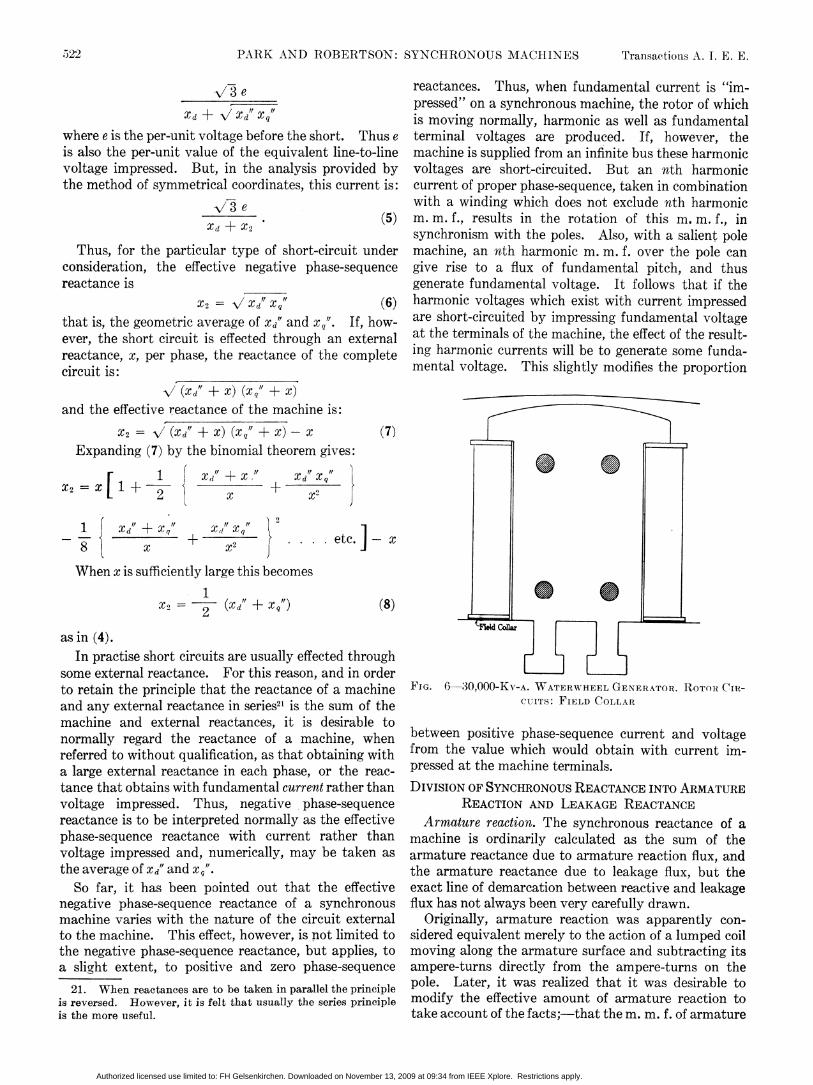
This increase in rotor m. m. f. is responsible for the sient reactance proper is then the reciprocal of the cur-familiar fact that the initial short-circuit current of a rent that would exist at t = 0 i- the high-speed termsmachine is greater than that obtained under sustained were absent. These relations may be made clear byconditions, after the induced d-c. currents in the field reference to Fig. 5, which shows the observed values ofand additional rotor circuits have died away. The symmetrical component of armature current from aresultant armature current is calculated in terms of the three-phase short-circuit test on a large water wheelvoltage before the short-circuit, as the ratio of that generator. The test was taken at reduced voltage sovoltage to a value of reactance referred to as the as to exclude saturation, and the per-unit values oftransient reactance of the machine. current have been multiplied by a factor so as to referMore specifically, this reactance is, of course, the to a test at normal voltage without saturation.
direct component of transient reactance, since it in- The per-unit current is expressible in this case as,volves only reactive or direct axis component of cur- i = 1.54 + 1.83 e-653t + 1.06 e-'" ,rent. Thus, direct transient reactance, Xd', iS the term with high decrement factor being due
e to the presence of a copper short-circuiting collar atXd the top of the pole. The values of direct transient
reactance are then,where e is the voltage preceding short-circuit and i is 1.0the symmetrical component of armature current just Xd' = direct sub-transient = 1.54 + 1.83 + 1.06after the short-circuit.The exact interpretation of this definition would = 0.226
imply that the current i is to be measured as the value and,of the envelope of the wave of symmetrical component 1.0of current, as projected to the instant of short circuit. Xd' = transient = 154 + 183 = 0.297But, in machines with closed rotor circuits in addition
Authorized licensed use limited to: FH Gelsenkirchen. Downloaded on November 13, 2009 at 09:34 from IEEE Xplore. Restrictions apply.

518 PARK AND ROBERTSON: SYNCHRONOUS MACHINES Transactions A. I. E. E.
So tar, transient reactance has been interpreted only defined as the per-unit value of positive phase-sequencein terms of the no-load short-circuit current of the voltage, due to the sudden application of a positivemachine. But, clearly, it may also be regarded as the phase-sequence current of normal amount; whilereciprocal of the ratio of suddenly applied balanced transient reactance is the corresponding apparent valuecurrent, to the reactive voltage due to this current. that obtains after the "high-speed" transients have diedIt is, therefore, similar to synchronous reactance, out. The four coefficients will, therefore, beexcept referring to suddenly applied instead of sus- Xd' direct transient reactancetained currents. From this standpoint it will of course xq' quadrature transient reactancehave both a direct and quadrature value, each of which Xd" direct sub-transient reactancein turn can be transient or sub-transient. If, however, x q"' quadrature sub-transient reactanceas is often the case, there is no really effective winding It has been pointed out that the direct sub-transientin the quadrature axis of the machine, the transient reactance can be determined from short-circuit tests.reactance in this axis should be taken equal to syn- It is also possible to measure it by suddenly opening up achronous. Thus, the term sub-transient reactance will sustained short circuit, that is, applying the equivalentalways refer to the "high-speed" phenomena in either of a negative current equal in magnitude to the sus-
tained current. Also, either direct or quadrature< I; - - - -c;FII t L1 bransient reactance can be found by impressing a direct
-- -_g_ _ l _ ,or quadrature voltage, respectively, on the terminals,-jLL- - - --__ _ I-directly or through a reactance. In all of these cases
4------- - ---{ the ratios of voltage to current, as shown on oscillo-14-t-t tt+-lt- +t- t. -tl1 grams, vary progressively from an initial value equal to
sub-transient reactance, through transient, to a final-1 -!-..1;X < A sTvalue equal to synchronous reactance.
3 1 Another method which is sometimes useful in deter-)z-3T -> < X r- p X X mining Xd' is to determine oscillographically the time-
Iiit-1< -; +4t-l tt-t constant of the decay of armature voltage and current,_ __i-4 7it _ _- -X respectively, with the armature open-circuited and
- 2 0 | X--- 11X Xshort-circuited. If these time-constants are respec--L t = tively To and T0', Xd' may be found from the relation"1
-1r 1-;S : tt r [ + provided thatXdis already known.
t--tl I- t I I I I \ I tA convenient method, which may be used in testingXL1L -l l-XIl I_ for both Xd"'2 and xq"13 is to apply a single-phase line-to-
0o L I_ - . XJ line voltage to the machine, the rotor being held still.0 '0-5 1.0 SECONDS 1.5 The field is shorted through an ammeter and the rotor
FIG. 5-DECREMENT OF SYMMIETRICAL COMPONENT OF moved until the meter reading is a maximum, at whichCURRENT THREE-PHASE SHORT CIRCUIT ON A 20,000-KV-A. position the rotor is directly under the center of theWATERW-HEREL GENERATOR phase. The direct sub-transient reactance, in ohms,
is one-half'4 the ratio of the armature voltage to theaxis. Moreover, if, as in the case of the machine to t .which the data of Fig. 5 refer, there happens to be norotor winding in the quadrature axis, the sub-transient The pole is moved slowly until the field ammeter
quadrature reactance will also equal the synchronous in reads zero, showing that the pole is in quadrature withquadrature reactance,in whil calsoequal tthe axis of magnetization. Then, the quadrature sub-
transient reactance, in ohms, is again one-half14 thexq" = Xq1 = Xq. ratio of the armature voltage to the armature current.
On the other hand, for machines equipped with amor- For delta-connected machines the line-to-linetisseurs, the value of the sub-transient quadrature reactances are similarly divided by two and the equiva-reactance will be different from the corresponding syn- lent Y-circuit used.chronous value, although, as before, 11. See Part II.
'= Xq 12. If there are no auxilia,ry windings on the rotor this reac-since there is no really effective winding in this axis. tance is transient, i. e., xci'. W=ithout such windings the methodIn practise, an amortisseur always has a decrement may also be used to obtain synchronous reactance by leaving the
suffcietlyighsotat ts ractnce s sb-trnsint. 13. If amortisseur windings are not present this reactanceThus, the per-unit sub-transient reactance of a is the quadrature synchronous reactance.
machine, in either the direct or quadrature axis, is 14. See Appendix H.
Authorized licensed use limited to: FH Gelsenkirchen. Downloaded on November 13, 2009 at 09:34 from IEEE Xplore. Restrictions apply.

Feb. 1928 PARK AND ROBERTSON: SYNCHRONOUS MACHINES 519
Negative phase-sequence reactance. In the case of a where a is the sustained component of current, and b, c,machine rotating synchronously the application of etc., are the transient components of current with time-fundamental negative phase-sequence current gives constants Tb, Tc, etc., respectively. In practise all butrise to negative phase-sequence fundamental and one of these time-constants will be small, i. e., less thanpositive phase-sequence third harmonic voltages from about one-twentieth sec., while for dead short-circuitsline-to-line and from line-to-neutral. The per-unit neg- the remaining time-constants will vary in large machinesative phase-sequence reactance of amachine is thus equal from about 0.5 to 2.5 sec.to the per-unit fundamental phase voltage, or the per- Thus, a few cycles after the occurrence of a short,unit line-to-line voltage, due to normal negative phase- from an initial condition of no-load and voltage e, thesequence current supplied at the machine terminals. armature current will beOn the other hand, if the rotor is not moving exactly r 1 11 1
synchronously the line-to-line voltages will not be i = e -+ -purely fundamental, but, as is shown in Part II, theywi1l LXd Xd Xdcontain slip frequency components. On this account, where To' is the short-circuit time-constant of thethe direct determination of negative phase-sequence machine.reactance by test is often inconvenient. If the machine is operating at no-load and its fieldHowever, it can be determined very easily by static winding is short-circuited, the variation of armature
test since the negative phase-sequence reactance of a voltage, shortly after the beginning of the transient, willmachine is very nearly equal to the average"5 of Xd' and follow a decrement having a time-constant To, which isXq/ i. e., larger than the short-circuit time constant To'. These
Xd' + XQ time-constants are related by the simple expressionX2 2 Xd_
=To' - To.Zero phase-sequence reactance. The application of d
fundamental zero phase-sequence current to a syn- As it happens that the open-circuit time-constant ofchronous machine gives rise to pulsating third harmonic most large machines is about five sec., the above rela-m. m. f. in the air-gap and end-windings, and to a slot tion provides an easy means of determining Tot when theflux the magnitude of which varies widely with the wind- other two quantities are known. The time constanting pitch. Thus, with other than full pitch coils, the slot T for a short circuit through an external reactance x isflux is diminished by the presence, in the slots, of coil then given assides carrying current in opposite directions. Zero XdI + xphase-sequence slot reactance is thus very sensitive to T=- To.pitch, and because of the fact just previously mentioned Xd + X
is a minimum at 2//3 pitch. The zero phase-sequence This also applies to the case of single-phase short cir-air-gap leakage also varies accordingly and disappears cuits. Thus, on single-phase short circuits, the positiveat 2/3 pitch, since in this case there is no air-gap m. m. f. phase-sequence component of current is to be calculatedThere is no armature reaction m. m. f. due to zero as the current that would exist when an equivalent16phase-sequence currents. Hence zero phase-sequence three-phase short circuit is applied.reactance is very small, say, from 15 to 60 per cent of the In the case of short circuits under load the time-direct sub-transient reactance. The effect of the constants of the rotor circuits in the quadrature axismotion of the rotor is very small, and, as a consequence, are also involved. Except for solid rotor turbo alter-there are no appreciable harmonic voltages. Per-unit nators, these are all so fast, however, as not to meritzero phase-sequence reactance is defined as the per-unit attention from an operating standpoint.phase voltage with normal zero phase-sequence current The case of turbo alternators is also complicatedapplied. While its definition implies a condition under to some extent by the large amount of saturation whichwhich the rotor is moving at normal speed, the difference exists in the rotor leakage paths. The effect of satura-in test result, if the rotor is stationary, is inappreciable. tion in such paths is not confined to turbo alternators
only, but is encountered to some extent in short circuitsDECREMENTS . of salient pole machines. Its effect does not, however,
Symmetrical component of current. As pointed out in greatly modify the general conclusions stated.the discussion of transient reactance, the decrementcurve of the transient armature current of a machine on 16. The equivalent reactance of a line-to-line short is the neg-short-circuit will, in general, be composed of several ative phase-sequence reactance viewed from the point of short,while for line-to-neutral shorts it iS the sum of the negative andsimple decrement terms, or exponentials. That is, the zero phase-sequence reactances. The negative and zero phase-current will be expressible as a series sequence currents can, of course, be found by applying the con-
_ _ _ ~~~~~~~ditions which hold at any instant,-that for line-to-line faults, the= a+be Tb +cC T2c + positive and negative components of current are equal in the
-- ~~~~~~~~~~~~~~~fault;and that for line-to-neutral faults, all three components15. See Appendix D. are equal in the fault.
Authorized licensed use limited to: FH Gelsenkirchen. Downloaded on November 13, 2009 at 09:34 from IEEE Xplore. Restrictions apply.

520 PARK AND ROBERTSON: SYNCHRONOUS MACHINES Transactions A. I. E. E.
D-c. component. On dead short circuits, the time-constant of the d-c. component is 1 tvl
1 _X2T= 2 r seconds _l_._
while if the machine is short-circuited through an - c
external reactance, x, the time-constant is 22
1 X2 + xO c1 x2f + seconds _-2 w7rf r
where r is the armature resistance as a per-unitquantity. --I
The time-constant on single-phase short-circuit iscalculated as for the equivalent three-phase short- | cl ocircuit. _Range of magnitude of reactances and time-constants. n c cc
It is noticeable that in any certain type of machine theaverage value of each of the particular reactancesappears to be a rather constant quantity, the deviation 0 0
from which is not very great. Thus it is possible toobtain tables showing the general limits and the average L to
values of the reactances, such as Table II.z CC 1C L O CThe first figures in any group of three quantities
indicate the lower limit, the second figures are the Q f LO
average, and the third figures, the upper limit. It isunderstood that they are not absolute values, but are orepresentative of most machines. Where only twoquantities are mentioned, the lower and upper limits aremeant. If only one term is given it is the average v °°reactance. E-,;|Z|
PART II ¢_THEORETICAL CONSIDERATIONS
The general problem of calculating the performance C1~ 1: C
of a synchronous machine does not admit of any but LN L V
the most difficult forms of analysis, unless the effects of 00 0 0 oo
saturation and hysteresis are neglected. Therefore, | lthey are not considered in the analysis which follows.Practically, these effects are small in a large number of z
cases. In those cases where their consideration be-comes necessary, the final result, or the coefficients, may |be "shaded."
Since saturation and hysteresis are neglected, linear I*relations exist between current and magnetic flux. It 0then follows, as is shown in detail in Appendix A, that N j °for a given motion or position of the rotor, the currentsand voltages in any part of the machine, due to any - -currents or voltages impressed at its terminals, may be . .found by superposing the effects that would result from . .the action of each separately. Thus, there will exist.factors of proportionality between the voltage or current ..~impressed at any terminal, and the voltages and cur- Q , .rents at all other points of the machine. | , *°lc
For instance, if the armature of the machine iS open- S .t,tcircuited, a steady voltage impressed on the field will | ;=@ ;a-give rise to a steady direct current in the field, and to X .¢tfundamental and harmonic voltages at the armature iaW a *terminals. On the other hand, if, say, one phase of the m
Authorized licensed use limited to: FH Gelsenkirchen. Downloaded on November 13, 2009 at 09:34 from IEEE Xplore. Restrictions apply.
Feb. 1928 PARK AND ROBERTSON: SYNCHRONOUS MACHINES 521
armature is short-circuited, a steady voltage applied to fundamental and a positive phase-sequence thirdthe field will give rise to steady and harmonic currents harmonic. Neglecting the effect of the resistance ofin the field, and harmonic currents and voltages, the closed rotor circuits as regards double frequencyrespectively, in the shorted and open armature phases. current, the per-unit value of the fundamental com-The ratios of these various currents or various voltages ponent of current with normal negative phase-sequenceto the impressed field voltage may be referred to as the voltage applied is approximatelycharacteristic coefficients of the machine with reference 1 1 1 \to the particular condition of operation and the particu- 2
,, + D,J (1)lar terminal quantity impressed, which in the illustra- dX Xqtive case under consideration happens to be field corresponding to a reactance:voltage. 2 Xc" X"
In general, characteristic coefficients can be estab- Xd xq (2)lished to cover any combination of impressed and result- X" + x(ant quantities, of any frequency, in any of the four If this voltage were applied through an externaldistinct terminal circuits17 of the machine comprising reactance, x, the total reactance of the circuit would be:the three armature phases and the field winding. 2 (Xd" + x) (Xq' + X)These coefficients may be further distinguished from x + x + x " + xeach other according to the rate and time-phase of Xd qapplication of the impressed quantities, the character Thus, the effective negative phase-sequence reactanceof the terminal circuits on which these quantities may of the machine would be:be impressed, the motion and position of the rotor, and 2 (Xcd" + x) (Xq," + x)the time-phase of the resultant quantities relative to the x2 = Xd" + Xq" + 2 x -ximpressed quantities.The general problem of classifying and establishing a 2 Xd" Xq,/' + X (Xd" + XqX0)
nomenclature for all of the various types of coefficients Xd" + Xql + 2. (3)would be difficult, especially as there is no generallyaccepted name for the voltage, due to a voltage, or the If x is sufficiently great this reactance becomes:current due to a current.18 Moreover, the necessity 1for a careful study of the broad subject is not pressing x2 = 2 (Xcd" + X8") * (4)at present, although it is anticipated that as progressis made in the analysis of machine performance, the Physically, the effect of the external reactance isrecognition and employment of an increasing number of to force the current in the machine to be sinusoidal, andcharacteristic coefficients will take place. to permit the existence of a third harmonic voltageHowever, the specific problem of classifying and across each phase. This results in a change in the
studying that particular class of coefficients, which effective negative phase-sequence reactance of therefers to the reactive voltages and currents in syn- machine. This change may be considerable. Forchronous machines, is relatively straightforward: at instance, the ratio of the two extreme types of reactancethe same time it is important, in view of the practical given by equations (2) and (4) might be as high as fivesignificance of this type of coefficient in the study of the to one.19phenomena occasioned by short circuits. It is this In the case of sustained single-phase line-to-linecomparatively restricted aspect of the general subject short circuit, on the other hand, or in the equivalentwhich is considered in the present paper. case of fundamental voltage impressed from line-to-line,
Following conventional practise, these particular the per-unit fundamental component of current is showncharacteristic coefficients which express the factors of by Doherty and Nickle to be :20proportionality between reactive voltage and current, 19. In the case of the small machine employed in the tests illus-are referred to, generally, as reactances. trated in Doherty and Nickle's paper Synchronous Machines
Dependence of Reactance on Terminal Circuit. Unlike IV the negative phase-sequence coefficient is 0.40 when negativephase-sequence voltage is impressed directly, and is 1.99 when the
aimdeplendere thechractaeer, these tereatanc are not voltage is impressed through a large reactance, or a ratio of five,independent of the character of the terminal circuit. based on the smaller quantity. This, however, is a very extremeThus, when negative phase-sequence voltage is applied case.directly at the terminals of a three-phase machine, the In machines of normal design, the ratio would be ap-phase current contains a negative phase-sequence proximately,
___________ W~~~~~~~~~~~~~~~~~biater-wheel generators .........1 .3017. Three-phase machines are referred to. The armatures of Synchronous Motors and Condensers .. 1 .04
single-phase machines may be regarded as three-phase armatures Turbine Generators.1 .00with one leg left idle in operation. The exact difference in these two types of reactances is dis-
18. The term short-circuit ratio, expressing the per-unit arma- cussed in detail in Appendix D.ture current on sustained short circuit due to the applica.tion 20. This form follows from equation (27b) of the paper men-ef no-load field current, is an exception to this rule. tioned by substituting XD = 2 Xdi, XD' = 2 xd"', and XQ' =2 Xq".
Authorized licensed use limited to: FH Gelsenkirchen. Downloaded on November 13, 2009 at 09:34 from IEEE Xplore. Restrictions apply.
522 PARK AND ROBERTSON: SYNCHRONOUS MACHINES Transactions A. I. E. E.
e reactances. Thus, when fundamental current is "im-pressed" on a synchronous machine, the rotor of which
Xd + V/ Xd' Xq is moving normally, harmonic as well as fundamentalwhere e is the per-unit voltage before the short. Thus e terminal voltages are produced. If, however, theis also the per-unit value of the equivalent line-to-line machine is supplied from an infinite bus these harmonicvoltage impressed. But, in the analysis provided by voltages are short-circuited. But an nth harmonicthe method of symmetrical coordinates, this current is: current of proper phase-sequence, taken in combination
N73 e with a winding which does not exclude nth harmonic(5) m. m. f., results in the rotation of this m. m. f., inXd + x2 synchronism with the poles. Also, with a salient pole
Thus, for the particular type of short-circuit under machine, an nth harmonic m. m. f. over the pole canconsideration, the effective negative phase-sequence give rise to a flux of fundamnental pitch, and thusreactance is generate fundamental voltage. It follows that if the
x2 = '/Xd' Xq (6) harmonic voltages which exist with current impressedthat is, the geometric average of XI' and Xq". If, how- are short-circuited by impressing fundamental voltageever, the short circuit is effected through an external at the terminals of the machine, the effect of the result-reactance, x, per phase, the reactance of the complete ing harmonic currents will be to generate some funda-circuit is: mental voltage. This slightly modifies the proportion
X(Xd" + X) (Xq" + X) ___
and the effective reactance of the machine is:
X2 = (Xd + X) (Xq + x) -x (7)Expanding (7) by the binomial theorem gives:
1 Xd"ft+X" Xd" ,
X2 x [ + 2 x + x2 l2 x
1 - d"+Xq" + Xi q2 . etc ]-x
When x is sufficiently large this becomes
x2 = 2 (Xd' + Xq ) (8) 0
asin (4).In practise short circuits are usually effected through
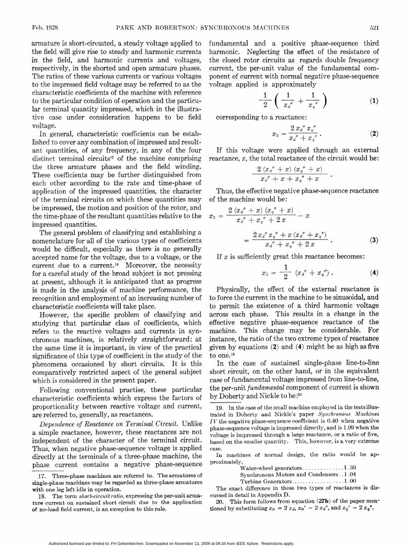
some external reactance. For this reason, and in orderto retain the principle that the reactance of a machine FIG. 6 FI0,000KV-A. WATERWRREL GENERATOR. ROTRIR Cut-and any external reactance in series21 is the sum of the CUITS: FIELD COLLARmachine and external reactances, it is desirable tonormally regard the reactance of a machine, when between positive phase-sequence current and voltagereferred to without qualification, as that obtaining with from the value which would obtain with current im-a large external reactance in each phase, or the reac- pressed at the machine terminals.tance that obtains with fundamental current rather than DIVISION OF SYNCHRONOUS REACTANCE INTO ARMATUREvoltage impressed. Thus, negative phase-sequence REACTION AND LEAKAGE REACTANCEreactance is to be interpreted normally as the effective Armature reaction. The synchronous reactance of aphase-sequence reactance with current rather than machine is ordinarily calculated as the sum of thevoltage impressed and, numerically, may be taken as armature reactance due to armature reaction flux, andthe average of Xd" and x,". the armature reactance due to leakage flux, but theSo far, it has been pointed out that the effective exact line of demarcation between reactive and leakage
negative phase-sequence reactance of a synchronous flux has not always been very carefully drawn.machine varies with the nature of the circuit external Originally, armature reaction was apparently con-to the machine. This effect, however, is not limited to sidered equivalent merely to the action of a lumped coilthe negative phase-sequence reactance, but applies, to moving along the armature surface and subtracting itsa sligfht extent, to positive and zero phase-sequence amnpere-turns directly from the ampere-turns on the
21. Wihen reactances are to be taken in parallel the principlepoe Lar,iwsralzdttitaseiabeois reversed. However, it is felt that usually the series principle modify the effective amount of armature reaction tois the more useful. take account of the facts;-that the m. m. f. of armature
Authorized licensed use limited to: FH Gelsenkirchen. Downloaded on November 13, 2009 at 09:34 from IEEE Xplore. Restrictions apply.

Feb 1928. PARK AND ROBERTSON: SYNCHRONOUS MACHINES 523
reaction existed at the armature surface and, hence, a slip frequency in these circuits. Therefore, it appearsgiven amount of it did not have the same effect as if it logical that, in general, armature reaction should bewere due to the field winding; and that the principal taken to include all of the m. m. f. that is stationary withcomponent of m. m. f., and the only one that is station- respect to the rotor, since, and especially in inductionary with respect to the poles, is distributed sinusoidally motors or turbo alternators, the end-winding m. m. f.along the armature surface. can produce a flux which links the rotor circuits.
Hence, this point of view, i. e., that armature reactionexists in the end windings as well as along the stacked
Anortisseur length of the machine, is favored by the authors.C_ Short Circuiting FieldCollar However, from a practical point of view, the net
effect of the armature reaction in the end-windings of a
salient pole machine is usually negligible as far asregards the induction of flux in any of the rotor circuits.Consequently in the present state of the art, at least,it is legitimate to regard all the end-winding flux ofsalient pole machines as leakage flux.
In the case of turbo alternators, this assumption isless correct, although the action of the iron end-ringsemployed on these machines tends to reduce the mutual
FIG. 7-150-KV-A. HIGH-SPEED SYNCHRONOUS MOTOR. ROTORCIRCUITS: AMORTISSEUR, FIELD COLLAR
Thus, in recent theory, armature reaction is under- Amortisurstood to refer to the space fundamental or stationarycomponent of m. m. f. due to the armature. However,some question arises as to whether the term should beinterpreted to apply to the total synchronous m. m. f.,due to the armature, thus including the synchronousm. m. f. in the end-windings, or whether it should belimited so as to refer only to the m. m. f. along thestacked length of the machine.
Obviously, the answer to this question should dependon the relative value of each alternative as regards
AmortiBseur Fic. 9-25,000-KV-A. SYNCHRONOUS CONDENSER. ROTORCIRCUITS: AMORTISSEUR, FIELD COLLAR
flux between armature and field, and, thus, lessen thedegree of approximation involved. However, thesemachines have a relatively small leakage reactance,so that the error involved, practically, in treating end-flux as all leakage is small here also.On the other hand, in the case of induction motors,
there can exist a comparatively large amount of end-flux. Since a considerable part of this flux may bemutual with the rotor winding, the approximationthat end-flux is all leakage cannot be satisfactorily
FIG. 8--240-KV-A. LOW-SPEED SYNCHRONOUS MOTOR. ROTOR employed.CIRCUITS: AMORTISSEUR Thus, on account of physical appropriateness, and to
obtain consistency, it is desirable, normally, to considercalculating the performance of the machine. But the all armature m. m. f. which is stationary with respectchief purpose of separating out the voltage due to to the rotor as armature reaction. In practicalarmature reaction from the total synchronous reactance computations, however, it is desirable, at present, todrop is to consider separately those fluxes which can limit the term to the m. m. f. in the stacked length ofnormally penetrate the rotor windings, and which can, the machine, except in the case of induction motors andunder abnormal conditions, induce direct current or special synchronous machines.
Authorized licensed use limited to: FH Gelsenkirchen. Downloaded on November 13, 2009 at 09:34 from IEEE Xplore. Restrictions apply.

524 PARK AND ROBERTSON: SYNCHRONOUS MACHINES Transactions A. 1. E. E.
In addition to establishing the conception of armature far as possible so that this effect is small in order toreaction as denoting a particular type of m. m. f., it has eliminate losses in these windings.appeared desirable to broaden the scope and applica- Methods of calculating leakage reactance are givention of the term so that it may apply not only to m. m. f. by Mr. P. L. Alger in a companion paper on this subject.but also to fluxes and their linkages. Thus, it is pro- THE IDEAL SYNCHRONOUS MACHINEposed to characterize by the qualifying term armatureratoall ths phnmn whic deen upo th The ideal synchronous machine has a sinusoidalreactionall thosehenomenahichdepenupontheopen-circuit voltage wave, and leakage reactanceaction of the synchronous component of armature unaffected by rotor position, i. e., only armature reac-M. m. f. In this way there are: tion flux is affected by pole position. Practically, theA. M. m. f. of armature reaction, or armature reaction divergence of machines from this ideal type is often
proper; all the synchronous armature m. m. f. important; for example, as a cause of circulating cur-B. Flux or flux density of armature reaction; that rents, or, in the case of motors, of locking at part speed.
component of flux, or of flux density at any point of the In a large number of cases, however, it is legitimate toair-gap or in the rotor, which is due to the armature neglect these differences. The caloulation of thereaction m. m. f.; under normal conditions, all that flux electrical behavior of an ideal machine of this type canor flux density which is stationary with respect to the be accomplished in terms of a relatively small number ofrotor. characteristic constants. Thus, it may be shown24 that
C. Linkages of armature reaction; the linkages with the per-unit linkages in phase a of an ideal synchronousany circuit on the armature, or rotor, of the fluxes of machine are expressed asarmature reaction.
D. Reactances of armature reaction; the reactive 4{a = Idos 0-I,q sin 0- 3 (ia + i6 + ic)coefficients expressing the voltages of armature reaction(i. e., linkages) in any circuit on the armature, or Xd rXq+ ]crotor, due to normal armature current. - La2-The reactance of armature reaction, or in the case of
induction motors, the magnetizing reactance, will, Xd - xq rhowever, when referred to without qualification, mean 3 L ia Cos (2 0) + ib cos (2 0 - 120)the per-unit armature fundamental linkages due tonormal positive phase-sequence armature current and + ic cos (2 0 + 120) (10)will have direct and quadrature components, thus:
Xad = direct reactance of armature reaction where,iJa, tb, and tc are the instantaneous currents in phasesXaq = quadrature reactance of armature reaction. a, b, andc.
Methods of calculating armature reaction have been a, b, and c.Methods of calculatin armat2 Id is the nominal voltage, or per-unit rotor currentgiven by R. W. Wieseman. in the direct axis.Leakage Reactance. Leakage reactance is defined as I q is the nominal voltage, or per-unit rotor current in
that part of synchronous reactance which is not in- the quadrature axis, ahead of the poles.cluded in the reactance of armature reaction. Hence, 0 = electrical degrees in direction of normal rotationthere are two components between axis of poles and the magnetic axis of phase a.
Xld = Xd - Xad Axis of phase b is 120 deg. ahead of the axis of phase a.Xld = Xq - Xaq. Axis of phase c is 120 deg. behind the axis of phase a.
They are the reactances due to the flux in the slots and The linkages in phase b are similar except thatto the flux produced by the moving harmonic of (0 - 120) is substituted for 0 in the first two terms,m. m. f., which latter is that flux in the air-gap or end- ib for ia in the fourth term, and (120 - 0) for 0 in thewinding which is not normally stationary with respect fifth term. The linkages in phase c are obtained in ato the poles. Actually, the flux due to the nth harmonic corresponding way. From this, the voltage of any
1 phase can be obtained from the relationm. m. f. pulsates over the rotor at (1- ) times d 4an ~~~~~~~~ea= dt- na (11
normal frequency and, therefore, is subject to thedemagnetizing influence of the field winding and all In order to determine the reactance between theother closed rotor circuits. Consequently, in deter- armature and rotor, it is of great benefit to resolve themining the permeance23 of the air-gap to nth harmonic armature quantities under consideration with respectm. m. f. the effect of these circuits should be considered. to the two axes of symmetry of the poles, a procedureIn practise, however, the rotor circuits are adjusted as introduced by Blondeland further developed byArnold,
and Doherty and Nickle.22. Reference (5).23. Reference (8). .24. Reference (14).
Authorized licensed use limited to: FH Gelsenkirchen. Downloaded on November 13, 2009 at 09:34 from IEEE Xplore. Restrictions apply.

Feb. 1928 PARK AND ROBERTSON: SYNCHRONOUS MACHINES 525
To this end, and in analogy with their recognized I = X I -Xm idsignificance under steady conditions of operation, let in which4, X, Xm, and I refer to thiscircuit.the direct and quadrature components of current at In order to retain the valuable principle that theany instant, and under any condition of operation, be per-unit nominal voltage is equal to the total rotortaken equal to the instantaneous amplitudes of the current, it is desirable to define unit current in anydirect and quadrature components of armature m. m. f. circuit as that current which acting by itself producesIt may be shown25 that, at any instant, the magnitudes normal space fundamental flux at the armature surface.of these m. m. fs. are equal to the quantities In this way the nominal voltage at any instant is always
2 to be identified as the instantaneous rotor current.id = [ia cos 0 + ib cos (6 - 120) + ic cos (6 + 120)] Thus, in the direct axis, as
(12) Id = I+dIld + 12d + +Ind (14)
2 Transient Reactance. In analogy with the procedureiq [ia sin 0 + ib sin (6 - 120) + i, sin (6 + 120)] employed in determining the effect of the armature
circuit on the rotor, it is desirable to establish the con-The currents, id and iq then determine the reaction ception of instantaneous direct and quadrature com-
of the armature on the rotor at any instant. In general, ponents of armature linkages. If these componentsthere will be more than one rotor circuit. Consider, are defined ashowever, any particular circuit, say circuit h of the 2
Ad = 4'acos 0 + lb COS (6- 120) + f,c cos (0 + 120)]
(15)
V'q I 2-k[ta sin 0+4b sin (0-120)+I, sin (0+120)]
it may be verified that the simple relations, whichobtain between armature linkages and armature androtor currents under steady conditions, now hold atany instant. That is, under all conditions,
i/d Id- Xd id (16)litq I- Xq i'q
Transient reactance will then be the constant ofproportionality between V/ and i when i is suddenlyimpressed. Thus, if A 4Ad iS the sudden change in APdwhen a current A id is suddenly impressed, there is
FIG. 10-10,000-KV-A. TUtRBO ALTERNATOR. ROTOR CIR-CUITS: ROTOR IRON, METAL WEDGES X ' = - (17)
direct axis; that is, circuit h d. There will be factors Aid
of proportionality between the linkages, Thd, in this But, A A1d A Id - Xd Atidcircuit, the currents in every other rotor circuit in the where A Id is the corresponding increase in direct axisdirect axis, and the instantaneous direct component of rotor current. Therefore,armature current. Thus, there is A I
fhd = Xh,fd I 4- Xhld Ild + ... . . . . . .Xd = Xd- (18)XhfdI -I- Xhid lid + ______~~~~~~~~~~~~i+ Xhhd Ihd + . Ind - Xhmd Id (13)
where and similarly in the quadrature axis. The value ofI - per-unit field current A Id may be found by solving the n equations
lhd per-unit current in circuit h of the direct axis 4' = 'ifld 4=T2d = . . . "nd = 0 (19)Xhfd = per-unit mutual reactance of field with circuit subject to the conditions id = A id. A Iq may be found
Xh~dper-unit mutual reactance of circuit* d t similarly. We shall only consider in detail here theX pecrcunit nuuad ecac.o lclthdw case of a single rotor circuit. The equations (19)
Xhmd per-unit mutual reactance of armature with become in this case merelycircuit h d. 'c = XAooI- XmTAhd = 0
Similar relations exist in the quadrature axis except that from which it follows that, in this case,field current is not involved.X
If there is onlyone rotorcircuit, equation (13)becomes Xd' X=x- Xm (20)merelyX
25. Reference (14). where Xm is the mutual reactance of the main field wind-
Authorized licensed use limited to: FH Gelsenkirchen. Downloaded on November 13, 2009 at 09:34 from IEEE Xplore. Restrictions apply.

526 PARK AND ROBERTSON: SYNCHRONOUS MACHINES Transactions A. I. E. E.
ing with respect to the armature, and X is the total field in order to obtain symmetry with the equations forreactance. armature voltage a different procedure is here employed.
Calculation of Rotor Reactances. Before calculating In the following, normal voltage of any rotor circuit isthese quantities in per-unit terms it is necessary to that voltage which would exist in this circuit if normaldecide on an appropriate value of normal or unit link- flux changed through it at normal frequency. Normalages. It has been found convenient to specify normal resistance is then the ratio of normal I R drop to thislinkages in each rotor circuit as the product of normal voltage. In this way the per-unit voltage of any fieldflux by the number of series turns in the circuit. On circuit, say h d, isthis basis it is shown in Appendix G that, for any rotor d hdcircuit h, Ehd = dt + Rhd Ihd (25)
A(0dX htn = ) (21) while for the field circuit proper there is
Fh (0)
where, E= +RI (26)dtA (o) = 2.12 X (effective full-load armature ampere-
turns per pole, per phase). Decrements. Only the case of a machine with the fieldFh (0) = normal no-load ampere-turns of circuit h as the only rotor circuit will be considered. In this
with no saturation. case, if the armature is open-circuited, there isThus, the determination of the mutual reactances of ' = X IXmh can be reduced to the determination of no-load andexcitation ampere-turns in each rotor circuit. d IThe self and mutual rotor reactances at present dt
require flux plots for their determination, except in thecase of thetotalfieldreactance.so that the open-circuit time-constant of the field iscase of the total field reactance.
As shown in Appendix F, the latter is given by the To = X (27)expression R
F (o) If the machine is short-circuited through a reactanceX(=) x, and the effect of the resistance of the armature circuit
is negligible, as is normally the case, there iswhere K0 and L are given by formulas and curves inDoherty and Shirley's 1918 paper on reactances, 1 is [r Xm I Xd'±X XIthe stacked length of the machine, and 4 (o) is normal Xd + x Xd + xno-load armature flux. The transient reactance of a
Xd'+ x dlImachine with no additional rotor circuits is then given as E = X t + R IA(0) 1 Xd+X dt
Xd' X2d- F(o) K F (o) (23) so that the time-constant of the field, in this case, is4 (o) T Xd' + X
T To ~~~~~~~(28)Equivalent Circuits and Field Leakage Reactance. Xd + x
This general subject is treated mathematically in The time-constant on dead short-circuit isAppendix E. It is shown that any number of equiva- Xlent circuits can be constructed to represent the rela- To' = To (29)tion between armature and rotor currents and linkages. XdOf the various circuits which may be so constructed The effect of armature resistance, or of machinesthere is one in which the armature branch is Xld, and the operating in parallel, is to modify these results in amagnetizing branch is Xad. The field branch of this complicated way which will not be considered here.particular circuit has been referred to as the field leakage If, as is ordinarily the case, the resistance of the rotorreactance, and is denoted by Xi.26 It is shown in circuit is negligible, the time-constant of the directAppendix E thatX1 may be expressed in terms of the current in the armature depends upon the inductancequantities already described by the relation, of the armature to direct cuYrrent in the same way as
( Xad X \ the time-constant of direct current in the field dependsX Xad 1 (24) on the inductance of the field to direct current. The
/ ~~~~inductance of the armature to direct current is, however,Field Voltage. It sometimes is desirable to define the average of Xd"/ and xqtt and is thus equal to the
normal field voltage as the voltage which will just force negative phase-sequence reactance. Thus the time-normal current through the resistance of the field, but constant for the d-c. component in the armature is
26. ReferenGe (6). simply
Authorized licensed use limited to: FH Gelsenkirchen. Downloaded on November 13, 2009 at 09:34 from IEEE Xplore. Restrictions apply.

Feb. 1928 PARK AND ROBERTSON: SYNCHRONOUS MACHINES 527
x2 may be found by superposing the voltages due to anyT (radians) components into which this current may be resolved.
To illustrate, the armature voltage due to a fieldas stated in Part I. current I, and an armature current i, may be found as
ACKNOWLEDGMENTS the sum of the armature voltages due to the currents IThe authors wish to thank Messrs. R. E. Doherty, and i acting separately. That is, the voltage under load
C. A. Nickle, P. L. Alger, and Professor W. V. Lyon for may be found by subtracting from the no-load voltagecorresponding to the existing field current, the voltagetheir valuable suggestions, and Mr. R. G. Lorraine for d t this assistance in the preparation of the figures. cdue to the mpedance drop caused by the armature
* ~~current. Or, the voltage due to a currentAppendix A i = i, sin (t + a)
APPLICATION OF THE PRINCIPLE OF SUPERPOSITION TO can be found by superposing the voltages due toTHE ANALYSIS OF SYNCHRONOUS MACHINES currents
In a synchronous machine, as in a static device, the x - ia cos a sin tflux density at any point will be in linear relation to and,the total number of currents in every circuit of the i-aisln a cOs tmachine, providing saturation and hysteresis are acting alone.neglected. However, in a synchronous machine the So far it has merely been pointed out under whatfactors of proportionality between flux density and conditions the voltages due to a given current distri-current depend upon the angular position of the rotor. bution can be found by superposing the voltages due toThus, if the circuits in the machine are numbered 1, 2, any components of the distribution. Suppose, how-etc., the component of flux density in a given direction ever, that a given distribution of voltage is impressedat any point of the machine will be related to the at the machine terminals. Let this distribution becurrents in a manner shown by the following equation: characterized by the symbol e (t), and let ex (t) and ey (t)
0 = fI (0) iI + f2 (0) i2 + . . . etc. be component distributions into which e (t) may beConsequently, for agvepoiresolved so that e (t) = ex (t) + ey (t). Let the currents
Consequently, for a given position of the rotor, thedutoheeisrbinsei(),i.t)adi t)flux at any point in the machine may be found by Then theremustrbesuperposing the fluxes due to the current in every circuitacting separately. Also, the flux due to the current in i (t) = 1x (t) + t (t)any circuit may be found by superposing the fluxes due since this result fulfills all the conditions imposed by theto any components into which this current may be differential equations and terminal conditions of eachresolved, taken separately. circuit of the machine, provided that the position of theThe same rule will of course apply to linkages. Thus, rotor as a function of time, 0 (t), is the same with e (t),
the linkages in circuit I will be represented as ex (t), and ey (t) impressed.411 = X11 (0) il + X12 (0) i2 + . . . etc. Thus, it follows that the current distribution due to a
given distribution of armature voltage may be foundwhee isthe sinductance of circuit
1 and is by superposing the current distributions due to anythe mutual inductance of circuit 1 with re components into which the voltage distribution may
be resolved, provided that the motion of the rotor, as ad 41 function of time, is the same for the components as for
elr1Tl + d t the resultant.For example, if a machine is supplying current to a
/ dXi, (0) d 6 \ + di, d X12 (0) d 0 reactor and is then short-circuited, the current at any=r+ d 6 d t )+ Xi dt + d 6 77712 time after the short circuit may be found by super-
posing on the initial current distribution the fictitiousd t,9 currents which would be due to the application of a
+ N12 () dt + etc. negative voltage at the point of short circuit. Thisnegative voltage is equal and opposite to that which
But, since if i = ix + iy would have existed at the point of short circuit had the
dit d i2 d j short circuit not occurred, and it is assumed to bed t = dt+ d t applied with the machine unexcited.
On the other hand, if the machine is supplyingit follows that, for a given position and speed of the rotor, a kilowatt load, it would be only possible to calculatethe voltage in any circuit of the machine may be found the currents at the instant of short circuit in suchby superposing the voltages due to the current in every manner. This is because of the fact that generally,other circuit acting separately. Also, under the same in this case, the motion of the rotor would be differentconditions, voltage due to the current in any circuit before and after the short circuit on account of the change
Authorized licensed use limited to: FH Gelsenkirchen. Downloaded on November 13, 2009 at 09:34 from IEEE Xplore. Restrictions apply.

528 PARK AND ROBERTSON: SYNCHRONOUS MACHINES Transactions A. I. E. E.
in load effected by the short circuit. In the first instant, the currents in the "additional rotor circuits" have diedhowever, the inertia of the rotor would prevent a change away.in its motion. b. Alternating so slowly that the demagnetizingWhen current is impressed on the open circuits of a action of the "additional rotor circuits" is slight.
machine, in which closed circuits also exist, the same But if, with closed circuits on the rotor, the armaturelimitations apply as in the case for voltage. In both currents are sustained and of such a nature that theevents the currents and voltages due to the impressed armature m. m. f. is stationary and steady over thequantities depend on the complete variation in time of poles, Xd and xq are used as before.those quantities. Superposition is still legitimate, Finally, if there are closed circuits on the rotor, butsubject to the condition that the motion is the same for neither of the above conditions is fulfilled, it is generallythe components as for the resultant. possible to divide the currents into two parts; first, thoseThe general statement of the possibi'ity of super- which meet sub-transient or transient reactance, and
position is, then, that for a given motion or position of the second, those which meet synchronous reactance.rotor, the currents and voltages in any part of the The appropriate factor is then used with each type ofmachine, due to any currents or voltages impressed at current. For example, a single-phase line-to-lineits terminals, may be found by superposing the effects currentthat would result from the action of each taken i - = io cosseparately. is resolvable into positive and negative phase-sequence
Appendix B components as
REPLACING THE EFFECT OF INDUCED FIELD CURRENTS 1BY EMPLOYING TRANSIENT INSTEAD OF ia = io [cos (t - 30) + cos (t + 30)] = io cos t
SYNCHRONOUS REACTANCES A/3Equation (10), of Part II, gives the complete expres- 1
sion for the phase linkages of a synchronous machine ib = to [cos (t - 150) + cos (t + 150)] = - io cos tunder all conditions of operation. However, in the caseof rapidly changing or suddenly impressed currents,there is a definite relation between the currents in the 1field and armature circuits.97 As a consequence, the i c= io [cos (t -1- 90) + cos (t - 90)] = 0 (2b)field current terms may be replaced by terms involving V3armature currents. For normal motion of the rotor, the positive phase-
Thus, if the field circuit is closed, and the effects of a sequence component of current meets synchronousgiven armature current are to be calculated reactance, and the negative phase-sequence meets
a. only in the first instant after their sudden sub-transient reactance. Thus,application,
b. under sustained conditions of such a nature that Xd + Xqcos (t - 30)all m. m. fs. over the poles are pulsating, or moving at 2sufficient speed that the demagnetizing action of therotor circuits is practically complete, ±+ d -q cos (t + 20¾ + 30)it is merely necessary to substitute Xd' and xq"' or Xd' 2and xq' for Xd and xq in order to eliminate the terms Xd"+ x"lIdandI.. )/a =-
Xd'+ 2 t cos (t + 30)The linkages in phase a thus become +
¾o Xd"f + xq" r. b +_ i] Xd -xq"{a= 3 (ia + ib+c) [b + a + 2 cos (3 t + 2 0 + 30)
- Xd Xq" [ ia cos (2 0) + ibcos (2 0- 120) (3b)
+ i. (cos (2 6 + 120) 1 (ib) SIGNIFICANT ROTOR CIRCUITS IN ADDITION TO THEJ~~~~~~~~~~~~~FIELD
Xd' and Xq' replace Xd" and Xq" when the m.m. f.over The principal circuits in the rotor of a machine,the poles is besides the field winding proper, which are capable of
a. Suddenly impressed, but steady thereafter, and significantly affecting the behavior of the machineit iS desired to determine the effects of currents after under practical operating conditions, are listed in
27. Tha,tis, Id = (Xd -Xd"t) id and 'q = (xq - Xq") iq. Table III.
Authorized licensed use limited to: FH Gelsenkirchen. Downloaded on November 13, 2009 at 09:34 from IEEE Xplore. Restrictions apply.

Feb. 1928 PARK AND ROBERTSON: SYNCHRONOUS MACHINES 529
TABLE III Xd"t + Xq"
Significant rotor circuits a Cos (3 t + a)Type of Machine in addition to field 23
Water-wheel Generators Amortisseur, if used. +Xd Xqit
Synchronous Motors and Field collars, if used. 2 Cos (2 0 3 t - a) (4d)Condensers. Spider, unless laminated.
Turbine Generators Metal Wedges Xd"t + Xq"Rotor Iron, unless laminated. 'Pb = 2 cos (3 t-120 + a)
Figs. 6 to 10 show these circuits pictorially forrepresentative machines of each type. + 2 (5d)
Appendix DTHE NEGATIVE PHASE-SEQUENCE REACTANCE OF A etc.SYNCHRONOUS MACHINE WITH NEGATIVE PHASE- If fundamental negative phase-sequence voltage is
SEQUENCE VOLTAGE IMPRESSED maintained at the armature terminals, and if theWith normal negative phase-sequence current im- resistance of the armature is negligible, the armature
pressed on the terminals of a machine the phase cur- linkages will also be negative phase-sequence. Thisrents are, will require that both negative phase-sequence funda-
mental and positive phase-sequence third-harmonicta = cos t currents exist, having a definite ratio to each other.ib=COS(t ± 120) Thus, let i2(i) be the magnitude of the negative phase-
ic = cos (t - 120) sequence fundmental current, and i1(3) be the magni-It follows from equation (10), of Part II, and from tude of the positive phase-sequence third-harmonic
the fact that all the resultant fluxes are varying rapidly current. Also, suppose that the two are acting to-over the rotor,28 that the flux linkages in each phase gether, and let 0 = 0 + t. Then, combining equa-are, under these circumstances, tions (Id) and (4d),
Xd" + xq Xd Xq f Xd + Xq t
xd" +Xq Mi Xd" + X01'
'Pa +2 os(t+12 +is(2 0 + t-120)(2d + i2(1) 2 cos (3 t + a)Xd Xd" Xit
+x2 Cos(20-Ht-- 120) (2d) + i'(2 2 cos(3t+200 )
2
Xdl+Xd" o ( 20 d- Xq" Jf
+ 2 aeCos (2 0 + t + 120) (3d) I a=20S
and . ____Xd ___ Xd" X"(The variation in linkages will give rise to a voltage and, 22(1) 2 1(3) (7d)of fundamental frequency and a harmonic of(2 d O/d t + 1) times fundamental frequency. For 'Pa will contain only a fundamental component, i. e.,normal motion of the rotor these voltages will be funda- = i2(1) L Xd" + Xq (Xd" Xq/)2mental and third harmonic of which the fundamental 'Pa 2 2 (Xd" + Xq") ] costmay be found by analyzing the voltage wave over onecycle. However, if the speed of the rotor is not
2
2 Xd" Xq"exactly normal, the third harmonic in the terminal = X2Xdt + COS t (8d)voltage will pulsate at the slip frequency.
If normal third harmonic positive phase-sequence If 'Pa = cos tcurrent is impressed, i. e., if . 11{ 1
ta= COS (3 t ± ae) then q2(1) - 2~ Xd" + xq"Jib = COS(3 t-120±+ac) 1 1 1 x
xc= cos (3 t + 120 + a) and ---)= ( -+-g) Xd +Xqthe phase linkages become, 2 \ d X ' X"+q
28. See Appendix B. But under the conditions specified,
Authorized licensed use limited to: FH Gelsenkirchen. Downloaded on November 13, 2009 at 09:34 from IEEE Xplore. Restrictions apply.

530 PARK AND ROBERTSON: SYNCHRONOUS MACHINES Transactions A. I. E. E.
lb = cos (t + 120), i cos (t - 120), are determined by an external circuit such as anso that the current distribution, impedance, for example, a reactance and resistance in
1 1 1 series. Thus, it is possible to calculate the poweri= y ( + C)cos t factor of a current of any frequency induced in the field,
Xq or to determine the effect of external field reactance, etc.Xd _ z
,
The field voltage equation isXdlt + X/cos (3 t + 2 0°)] (9d)
Xd!' + Xq d__
1 1 __ dtib = + )[cos (t-120) E R2 Xd(xq where E(f) = X and R(X)=
-Xd" +-Xq" cos (3 t + 2 0- 120)j (lOd) Reactance and resistance of the field circuit are,Xd" + X q of course, to be calculated in per-unit and divided by
1 11 Xm. N'ormal or per-unit resistance is the product of2 ( it + ,, )[cos (t + 120) normal field current and resistance in ohms, divided
Xqxv by the voltage due to unit rate of change of normalXd"- X" flux linkages.
-x ^! + xql/ cos (3 t + 2 0O + 120) (lId) While the circuit just discussed is perfectly practical,Xd" + it is not at all the only circuit that can be constructed,
is just adequate to give rise to balanced normal negative nor is it in every way the best, since it may involvephase-sequence terminal voltage. It follows that the negative reactances. These latter, while not incon-application of balanced normal negative phase-sequence venient mathematically, are not entirely satisfactory
from a physical standpoint.(x -1) (Xtfn-i) A particular circuit previously employed29 is that
Ifi in which the armature branch of the equivalent circuit1.0 '(f) is made equal to the leakage reactance of the armature.
In this case write:
Fic. 11-EQUIVALENT CIRCUIT OF SYNCHRONOUS MACHINE =d= A - xd id (6e)DIRECT Axis, MAIN FIELD ONLY
voltage will give rise to a fundamental negative phase- r I 1sequence current of amount B'J=ABXL A J-BXmid (7e)
1/1 1\2 Xd" + q ) where A and B are arbitrary factors to be determined in2 \ Xd" xqt J I
The voltage may be applied either from line-to- such a way thatidand A can be employed in theline or from line-to-neutral.
Appendix E equivalent circuits. Then, it is necessary that
CONSTRUCTION OF EQUIVALENT CIRCUITS: CONCEPT OF Xd - A -x (8e)FIELD LEAKAGE REACTANCE or, A= Xd Xl = Xad
Consider a machie wBut, also there must be, on account of the nature of theConsider a machine without any "additional rotorcircuits." The equations relating per-unit armature equivalent circuit:and field linkages are, in this case: AB m e
V/d= I-Xdid (le) A XadXI- Xmid (2e) B = Xm= X* (10e)
The second equation may be put in the form,'i'(f) =X(f) I -i (3e) The equations may then be written:f-d = Xad I[f]- Xd id (lie)
where, t(t) = X ~~~~~~~'(4e trf = XLffrIr[ X-7 1-7 (12e)m ~~~~~~~~~~~IX() X_ where, I[]= - (13e)
But, equations (le) and (3e) are satisfied by the equiva- 'F[fJ = Xm 'I (14e)lent circuit of Fig. 11. _____
This circuit also holds good when the linkages to(f 29. Reference (6).
Authorized licensed use limited to: FH Gelsenkirchen. Downloaded on November 13, 2009 at 09:34 from IEEE Xplore. Restrictions apply.

Feb. 1928 PARK AND ROBERTSON: SYNCHRONOUS MACHINES 531
(Xad)2 surface, in the slots or inter-polar space, and at the endsXVf X X (15e) of the poles. This corresponds to the division of
armature leakage into air-gap, slot, and end leakage.The equivalent circuit in this case is shown in Fig. 12. The reactance X is then expressible as the sum of threeIn this case the field voltage equation is factors relating to the armature, inter-polar space, and
d pole ends respectively. Thus:E(f) - d t T[fI + R[f IIf X = Armature factor + inter-polar, or slot-factor
+ end factor.30Xad Xad Armature Factor. That component of flux, due to
where E[f l = Xm E and Ri = R current in any field circuit, which enters the armaturesurface will be assumed to link all of that circuit, a
The term X[f - Xad has been referred to as field condition which, it happens, is very generally fulfilled.leakage reactance-thus, Then the armature factor in field reactance, expressed
rxad 1xd as a per-unit quantity, is the ratio of the total flux toXl = X[f]- Xad = Xad - ij=j [Xad Xm] the space fundamental component of flux entering the
armature along one pole pitch. This factor was first
(16e) employed by Doherty and Shirley in their paper onThe formula for transient reactance may be obtained Reactance,30 and has received the designation K,.
by shorting the field side of the equivalent circuit. As pointed out by them, it is capable of being expressedReferring to Fig. 12 this gives: as the sum of the per-unit harmonics of flux, due to
(X(f)-1) _ 1 Xm normal current in the circuit under consideration,Xd' = Xd l -X = Xd-X divided by the order of the harmonic. Thus:
X1(f) X(f)k3 ks kn
(17e) K 1+ 3 + +. . + -or in terms of field leakage reactanceXoXac where the corresponding per-unit flux density wave is:
Xd'= X+X (18e) 1 + k3 sin 3 y+ k5sin 5 y+ ...etc.,Xl+Xad zy being the electrical angle measured from the quadra-IXm \ ture axis of the machine.
The form ( Xd- X ) is probably the easiest for It is interesting to realize, then, that harmonics inthe no-load flux wave of a machine are of the nature of
calculation since; leakage flux. This leakage flux can, however, beXd is calculated by standard methods. positive or negative according to whether the wave ofXm is calculated from a knowledge of no-load normal no-load flux is flat-topped or peaked. This would be
field current. indicated by negative constants in the above equation.Charts for determining K. for ordinary field windings
XI XXfIXad are available in the above mentioned paper on Re-*7 + If actance.iZd1d SXaS [f] Interpolar, or Slot, and End Factors. These factors
Xd -- lcomprise the field linkages due respectively to all theFIG. 12-EQUIVALENT CIRCUIT OF SYNCHRONOUS MA-ACHINE flux in the stacked length of the machine that does not
DIRECT AxIS, MAIN FIELD ONLY penetrate the armature surface and to all the end-flux.31 A formula for the field-flux linkages of salient-
X may be calculated without great difficulty. It is pole machines, due to flux which does not penetratemerely the ratio of the total field linkages to the the armature surface, has been given by Doherty andlinkages the field would enclose if normal space Shirley.32 Using the quantity L given in formula (33a)fundamental armature flux linked all of the field of that paper, the inter-polar and end factor becomesturns. equal to:
The construction of equivalent circuits when addi- N I(o) L 1tional rotor circuits are to be considered is more difficultthan in the simple case discussed and will not be treated t°here. Where l(o) = no-load field current in amperes
Appendix F ¢(o~) = no-load space fundamental flux per poleCALCULATION OF TOTAL FIELD REACTANCE1 grsstcelnthocr.
The calculation of total field reactance, i. e., the 30. Referetncct(10)al the1242. hihi ntspc fquantity or quantities X, is conveniently accomplished mental at the armature winding.by considering separately the fluxes at the armature 32. Reference (10), p. 1279.
Authorized licensed use limited to: FH Gelsenkirchen. Downloaded on November 13, 2009 at 09:34 from IEEE Xplore. Restrictions apply.

532 PARK AND ROBERTSON: SYNCHRONOUS MACHINES Transactions A. 1. E. E.
Thus, there is: 3 nfi(o)N I(o) L 1 2 Nh(o) Ih(o)
X = Ko + o(oAAppendix G or, Xhm AF(o) (6g)
RELATION BETWEEN Xm AND NO-LOAD EXCITATIONCURRENT where,
Ordinarily, the leakage reactance of a machine does A(0) = 2.12 (effective armature times per pole per phase)not have a transient value perceptibly different from X (normal r. m. s. armature current).its sustained one because the currents induced in the Fh(o) = no-load air-gap ampere-turns of any circuit .hvarious rotor circuits by the leakage fluxes are sensibly In particular,reactive in character, i. e., are nearly out of phase with A(0)the voltage producing them. Consequently, it is Xm - F() = per-unit mutual field reactance (7g)possible to neglect the changes in leakage reactance withmethod of application of current and to regard all the where,change that is necessary to account for the difference in F(0) = no-load air-gap ampere-turns of field.synchronous and transient reactance as being due to Using this relation, it is possible to reduce the calcu-the difference in the reactances of armature reaction lation of transient reactance to the following items:in the two cases. Therefore, in calculating the values A. Determination of synchronous reactance,of the constants Xm, Xmid, etc., it is only necessary to B. Determination of the "no-load field currents"consider the flux linkages of armature reaction, that is, of each rotor circuit, i. e., determination of currentthe flux linkages due to the space fundamental com-
ponent of armature m. m. f.necessary to give normal fundamental component ofponent of armature m. m. f. amtr lx n
But the effect of normal space fundamental m. m. f.acting in one axis of the rotoris just two-thirds33 of the C. Determination of self and mutual coefficientseffect of the maximum value of normal phase current. of the rotor circuits between themselves.That is, if i(o) is the current flowing in a single-phase Appendix Hwinding when the rotor is stationary and its axis inquestion is directly in line with the axis of magnetiza- BE RE EStion of the excited armature phase, the effect of normal PHASE REACTANCES
2 In accordance with the procedure discussed in Partspace fundamental m. m. f. is i(o. II, the impedances of a machine will be regarded as
3 the ratios of the sinusoidal components of voltage andNow consider any rotor circuit, for example, circuit h. current due to sinusoidal current in the windings.
The linkages in this circuit, due to a current of normal peak Since only sinusoidal currents of definite frequency, andvalue i(o) in one armature phase in line with circuit h, are only sinusoidal components of terminal voltage of
2 corresponding frequency, are to be considered, it follows3 N,h q(0) Xhm (1g) that it is legitimate to employ vector notation.
Thus, any current i = i0 sin (t + a) will be repre-
Thus the mutual inductance of circuit h and the arma- sentable as a vector i = io /a and the phase currentsture phase is will be representable as
a=il ± 1.2 + to2/3 Nh O(O) Xhm (2g) = \120+2/ 120 +0 (lh)
tb = i /120 +t2\12O +i0The linkages in the armature phase due to a normal The phase voltages are similar.
value of current Ih(o) in circuit h are, from the definition It may be readily verified that with a line-to-lineof normal current in any rotor circuit, simply34 connection between phases b and c,
nT tm(a) (3g) l _ / 90Thus the mutual inductance of the armature phase and 1 =-2=(2h)circuit h is +
nl ¢/(o) where i. } = line-to-line current of phases b and c,- ~~~~~(4g)while with a line-to-neutral connection from phase a
Ih^(o) to neutral,But since (2g) must be equal to (4g) it follows that
33. The effect offundamental m.m. f.only is tobe considered. t1= t 2 = (3h3ta)34. Since only the sinusoidally distributed component of the
armature winding is considered, harmonic linkages are neglected. where 4Oa = current from phase a to neutral.
Authorized licensed use limited to: FH Gelsenkirchen. Downloaded on November 13, 2009 at 09:34 from IEEE Xplore. Restrictions apply.

Feb. 1928 PARK AND ROBERTSON: SYNCHRONOUS MACHINES 533
Under normal conditions of operation, however, it xo = 3 X0d - Xsd =3 xaq- Xsq (13h)follows from the symmetry of every phase, that the Xsdfundamental components of the voltages due to any Xd" = 2 (14h)phase-sequence current distribution must be of the samephase-sequence as the current. Thus, subject to the xcondition of normal motion of the rotor, there is, x (15h)
ei = zi i,as mentioned in Part I.
e2 = Z2 X2 (4h) The values of per-unit single-phase reactances whicheO = z0 i, obtain with no closed rotor circuits may also be identi-
but the line-to-line voltage of phases b and c is fied as the per-unit single-phase armature inductances.eb., eb -e = 3 (ei - e2) \90 Thus, in treating the subject of short-circuit currents,
(Zl + Z2) is bc Zs Is bc (5h) Messrs. & Doherty and Nickle35 employ the relations,or line-to-line impedance = z, = Z, + Z2 + XSQ XSD - XSQ
Similarly it follows that, subject to the conditions line-to-line inductance= 2 + 2 cos (2 0')stated, line-to-neutral impedance is
Z1 +AZ2+zn zs +3zoline-to-neutral inductance3 3(6h) X:D + XZQ X+ZD - X 2 0
However, these relations do not obtain without 2 2special interpretation unless the rotor is moving where, 6' = 0 + 300normally. In case of an "ideal machine" with the rotor The idea of transient inductance has also beenstationary, thevaluesof single-phase reactance are given, introduced. For example, the transient line-to-lineby the value of Pa 4-'b with ia = i-b = 1, ic = 0, and inductance is,Vla with ia = 1, ib =i = 0, respectively, for a line-to- XSD' - XSQ/line or line-to-neutral connection. XQD + SQOS (2 0_)
Thus, with all rotor circuits closed, the line-to- 2 2line static reactance is In case machines with auxiliary rotor circuits were
Xd"- xq" to be considered, the conception of the subtransientXs Xd"I + Xq" + cos(2 0) - 2 cos (2 0 -120) inductance and the use of the doutle primed notation
would also be in order. Thus, for the transient+ cos (2 0 + 120)] reactances,
= (Xd" + X,z) + (Xd" - Xq") cos (2 0 + 60) (7h) XSD 2 Xd'd XSQ = 2 xqThe value of x, when the axis of magnetization of the , X0 + 2XI , = x-+2 Xqarmature coincides with the direct axis of the rotor is X2D 3 XIQ3
Xs = Xsd = 2 Xd" (8h) and for the sub-transient reactances,When the axis of the armature winding coincides with XSD" = 2 Xd", etc.the quadrature axis the value of x, is
Xs = Xs q = 2 x q/ (9h) Appendix I
The corresponding line-to-neutral reactances are, T o OfeIsN asMPLOYEwith all rotor circuits closed, The problem of devising a simple scheme, of notationwithalldrotorcircuits closed, which will be in accord as much as possible with existing
X., 3 + 3 ±cos 2 6 (10h) nomenclature has not been easy. The difficulty is due3 3 3 to the many terms which pertain to synchronous ma-
When the axis of the armature winding is in line with chines.thepoles The notation of the paper follows the somewhat
the poles 2 Xd' O X,dgenerally established principle that all armature quan-X X, = 0 + 2 Xd"t _0±O+ Xd (llh) tities are denoted by small letters or symbols, and all
x - xd - Ih33 field terms by large letters or symbols. The subscriptsand when the armature axis is in quadrature with the d and q refer to the direct and quadrature axes of magneti-
poles ~~~~~~~~~~zation.The corresponding single-phase line-to-linepoles ~~~~~~~~~~~andline-to-neutral quantities are recognized by the
X5X,q = X+ 2 xq" _Xo +Xsq (12h) subscripts s and a, respectively. Positive phase-x<,-x,, - 3 - 3 sequence terms may be indicated by the subscript1,but
These relations are useful in determining the values are usually given no special notation. Negative andof xO, Xd", and Xqt". Thus 35. Reference (2).
Authorized licensed use limited to: FH Gelsenkirchen. Downloaded on November 13, 2009 at 09:34 from IEEE Xplore. Restrictions apply.

534 PARK AND ROBERTSON: SYNCHRONOUS MACHINES Transactions A. I. E. E.
zero phase-sequence terms are specified by the sub- c. Use of zero as subscript.scripts 2 and 0, respectively, following the notation Except in connection with time-constants, 0 willintroduced by Mr. C. L. Fortescue.36 All transient indicate zero phase-sequence quantities, and (0) willquantities are signified by primes. imply normal, or per-unit quantities.
These compose, in the main, the group of indexes To = field time-constant with all armature phases open.required, but various modifications and special designa- Tro = armature time-constant with all rotor circuitstions were necessary. The notation is not peculiar to open.this paper but is largely the same as the system used by C. PRIME QUANTITIESDoherty and Nickle in their recent treatments of syn- .chronous machines. Although it is not urged that a. Wth reference to armature reactances:this notation be standardized, since the primary sustained no special indication.purpose has been to fill the requirements of the present transient-one prime, i. e., x'.article, the system may be helpful to others. sub-transient-two primes, i. e., x".A.ticle,thesystemMAJO QAIe TOlpful BEotheNTIb. With reference to time-constants:
field time-constant with all armature phasesCircuits shorted-Tof
Armature Rotor armature time-constants with all rotor circuitsclosed-r0'
Voltage . e E D. ALL SUBSCRIPTS CAPITALIZEDLinkages........... V TCurrent. ... . ...iI In the present scheme of notation, this form isM. m. f.A F reserved for the particular single-phase static reactancesReactance.... x X used by Doherty and Nickle in their paper SynchronousResistance ........... r R Machines IV, and discussed here in Appendix B.Time-constant........ T These are:Flux density .........
Time total static reactance XD(Electrical radians) t t static reactance due to space fundamental XAD
Electrical space angle along armature surface static leakage reactance XLDwith respect to phase "a" ly static transient reactance XDI
Electrical degrees in direction of normal rotation static transient fundamental reactance XAD'between axis of poles and magnetic axis of As these reactances are single-phase they are alsophase "a" 0 characterized by S and ; to indicate whether they are
B. USE OF SMALL SUBSCRIPTS IN NOTATION line-to-line or line-to-neutral, thusa. Direct and quadrature quantities. XSD, or X2D.
direct d Corresponding quadrature values are designatedquadrature q similarly by the subscript Q instead of D.
These apply to: E. MISCELLANEOUS TERMSpositive phase-sequence armature quantities E ICLAEU EMrostu quantities It is necessary to include a number of special termsrotor quantities which have not been discussed above. The notationsingle-phase static quantities used for these quantities is more or less arbitrary, butb *Distribution.niie s or r es rbtrr ub. DAstrebutuon. an attempt has been made to employ accepted symbols1. Armature quantities.-
positive phase-sequence 1, or no subscript as much as possible.negative phase-sequence 2 h = a subscript denoting any rotor circuit. Inzero phase-sequence 0 conjunction with d or q it signifies that thatsingle-phase line-to-line s circuit is in the direct or quadrature axis.single-phase line-to-neutral o- K 37 = a per-unit quantity expressing the ratio of theseparate phases a, b, c total flux to the space fundamental com-
2. Rotor quantities. ponent of flux entering the armature alongdirect d one pole pitch.quadrature q I = used asasubscript to denoteleakagereactance,
Where there are several circuits in any axis they are or used alone to denote length of armatureto be distinguished from each other by numeral sub- stacking.scipts, as X2d, except that the symbol, f, may be L3 = effective leakage lines per unit length of stack-retained for the field winding proper. If no subscript ing, linking the entire field winding when theis employed reference to the main field winding is field m. m. f. is one ampere-turn.
implied._ 37. First employed by Doherty and Shirley in their paper
36. Reference (11). Reactance, reference 10.
Authorized licensed use limited to: FH Gelsenkirchen. Downloaded on November 13, 2009 at 09:34 from IEEE Xplore. Restrictions apply.
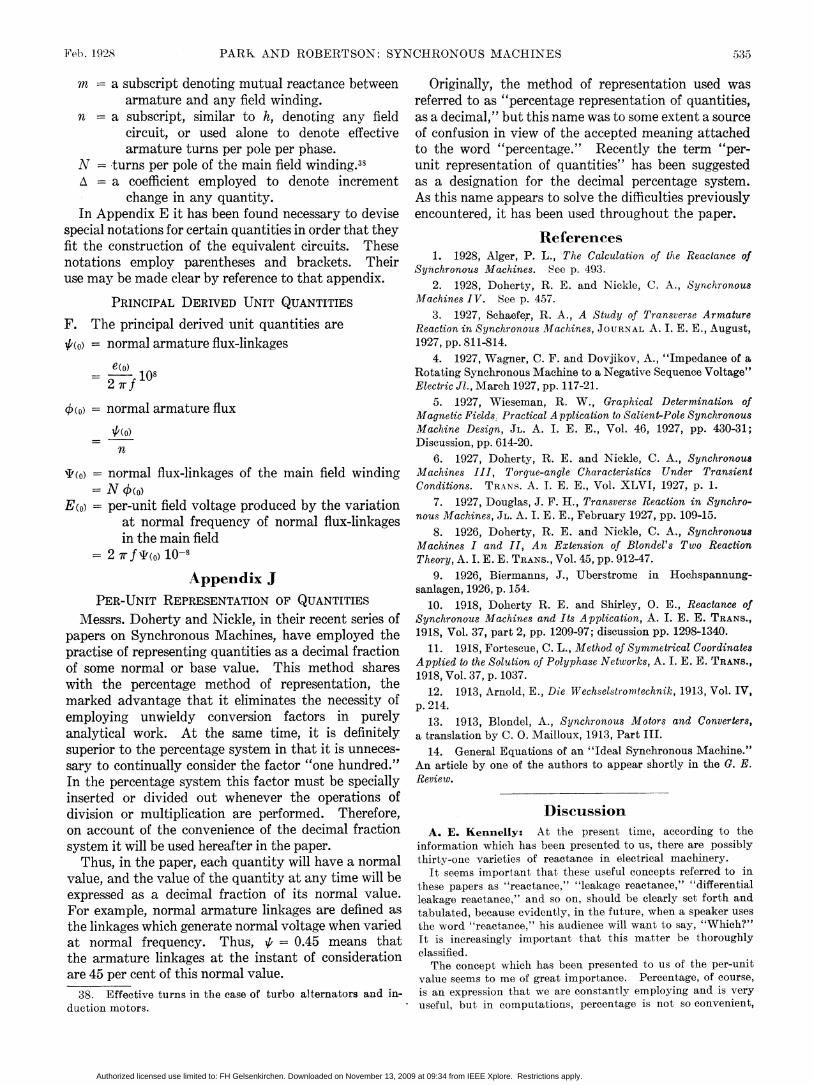
Feb. 1928 PARK AND ROBERTSON: SYNCHRONOUS MACHINES 535
m a subscript denoting mutual reactance between Originally, the method of representation used wasarmature and any field winding. referred to as "percentage representation of quantities,
n a subscript, similar to h, denoting any field as a decimal," but this name was to some extent a sourcecircuit, or used alone to denote effective of confusion in view of the accepted meaning attachedarmature turns per pole per phase. to the word "percentage." Recently the term "per-
N -turns per pole of the main field winding.33 unit representation of quantities" has been suggestedA = a coefficient employed to denote increment as a designation for the decimal percentage system.
change in any quantity. As this name appears to solve the difficulties previouslyIn Appendix E it has been found necessary to devise encountered, it has been used throughout the paper.
special notations for certain quantities in order that they Referencesfit the construction of the equivalent circuits. These Thencesnotations employ parentheses and brackets. Their 1. 1928 Alger, P. L., The Calculation of the Reactance of
Synchronous Machines. See p. 493.use may be made clear by reference to that appendix. 2. 1928, Doherty, R. E. and Nickle, C. A., Synchronous
PRINCIPAL DERIVED UNIT QUANTITIES Machines IV. See p. 457.F. The prncpa erve niqanii3. 1927, Schaefer, R. A., A Study of Transverse Armature
F. The principal derived unit quantities are Reaction in Synchronous Machines, JOURNAL A. I. E. E., August,,(o) = normal armature flux-linkages 1927, pp. 811-814.
e(o)4. 1927, Wagner, C. F. and Dovjikov, A., "Impedance of a
= o°10 Rotating Synchronous Machine to a Negative Sequence Voltage"2 7r f Electric Jl., March 1927, pp. 117-21.
normal armature)flux 5. 1927, Wieseman, R. W., Graphical Determination of¢(0)=normal armature flux Magnetic Fields. Practical Application to Salient-Pole Synchronous
O(o) Machine Design, JL. A. I. E. E., Vol. 46, 1927, pp. 430-31;Discussion, pp. 614-20.
6. 1927, Doherty, R. E. and Nickle, C. A., SynchronousTto) = normal flux-linkages of the main field winding Machines III, Torque-angle Characteristics Under Transient
= N 0(o) Conditions. TRANS. A. I. E. E., Vol. XLVI, 1927, p. 1.
E(o) -per-unit field voltage produced by the variation 7. 1927, Douglas, J. F. H., Transverse Reaction in Synchro-at normal frequency of normal flux-linkages nous Machines, JL. A. I. E. E., February 1927, pp. 109-15.
in the main field 8. 1926, Doherty, R. E. and Nickle, C. A., Synchronou8Machines I and II, An Extension of Blondel's Two Reaction
= wf''(0) 1O-8 Theory, A. I. E. E. TRANS., Vol. 45, pp. 912-47.
Appendix J 9. 1926, Biermanns, J., Uberstrome in Hochspannung-PER-UNIT REPRESENTATION OF QUANTITIES sanlagen, 1926, p. 154.
PER-UNIT REPRESENTATION OF QUANTITIES 10. 1918, Doherty R. E. and Shirley, 0. E., Reactance ofMessrs. Doherty and Nickle, in their recent series of Synchronous Machines and Its Application, A. I. E. E. TRANS.,
papers on Synchronous Machines, have employed the 1918, Vol. 37, part 2, pp. 1209-97; discussion pp. 1298-1340.practise of representing quantities as a decimal fraction 11. 1918, Fortescue, C. L., Method of Symmetrical Coordinatesof some normal or base value. This method shares Applied to the Solution of Polyphase Networks, A. I. E. E. TRANS.,of some normal or base value. This methodl shares 1918 vol. 37,p 1037.
with the percentage method of representation, the 19 .13 d,p1 .,12. 1913, Arnold, B., Te Wechselstromtechn2k, 1913, Vol. IV,marked advantage that it eliminates the necessity of p. 214.employing unwieldy conversion factors in purely 13. 1913, Blondel, A., Synchronous Motors and Converters,analytical work. At the same time, it is definitely a translation by C. 0. Mailloux, 1913, Part III.superior to the percentage system in that it is unneces- 14. General Equations of an "Ideal Synchronous Machine."sary to continually consider the factor "one hundred." An article by one of the authors to appear shortly in the G. E.In the percentage system this factor must be specially Review.inserted or divided out whenever the operations ofdivision or multiplication are performed. Therefore, Discussionon account of the convenience of the decimal fraction A. E. Kennelly: At the present time, according to thesystem it will be used hereafter in the paper. information which has been presented to us, there are possibly
Thus, in the paper, each quantity will have a normal thirty-one varieties of reactance in electrical machinery.value, and the value of the quantity at any time will be It seems important that these useful concepts referred to in
flthese papers as "reactanee," "leakage reactance," "differentialexpressed as a decimal fraction of its normal value, leakage reacetance," and so on, should be clea.rly set forth andFor example, normal armature linkages are defined as tabula,ted, because evidently, in the future, when a speaker usesthe linkages which generate normal voltage when varied the word "reactance," his audience will want to say, "Which?"at normal frequency. Thus, ,6 = 0.45 means that It is increasingly important that this matter be thoroughlythe armature linkages at the instant of consideration classified.
The concept which has been presented to us of the per-unitare 45 per cent of this normal value, value seems to me of great importance. Percentage, of course,
38. Effective turns in the case of turbo alternators and in- is an expression that we are constantly employing and is veryduction motors. .useful, but in computations, percentage is not so convenient,
Authorized licensed use limited to: FH Gelsenkirchen. Downloaded on November 13, 2009 at 09:34 from IEEE Xplore. Restrictions apply.