#139 awa news feb 2018
TRANSCRIPT
What a great start to the
year, two months of a full
newsletter, prepared well in
advance of the final date
and packed with infor-
mation, I believe, for most
of our readers. Thanks to all
of you who are submitting
the articles which make this
newsletter so great.
I must say, there have been
times when I have felt total-
ly frustrated, as do probably
many editors of small publi-
cations like this, when I
have had to scrounge the
internet searching for arti-
cles to fill the pages.
Fortunately there are many
publications out there that
are free to use, or simply
require authorisation from
the authors, and many
times it has been those that
have filled the pages.
Of course, it is always bet-
ter to have articles that are
home produced, because
they are more relevant to
the readership than are
articles imported.
My late Father used to
write short story articles
for Readers Digest and
many a time I can recall
him sitting at the dining
room table pouring over his
pages, with the proverbial
scrap bin next to him, more
often that not half full with
crumpled pages. All of his
short stories were hand
written with an expensive
Schaefer Ink pen that he
bought especially for his
writing. He had the most
neat and accurate hand
writing that I can ever re-
call seeing. It was almost
like perfect calligraphy.
After a few years, he
bought a Remington Elec-
tric type writer, which pro-
duced as much scrap as
what his hand writing did
at first, but certainly in-
creased the speed at which
his documents could be
produced.
I cannot say that this is
where I developed any de-
gree or will to produce publi-
cations of any kind, because
at that stage I did not even
know what he was writing
about.
Such a perfectionist was he,
that when he retired from
the working world, he be-
came an instructor at the
Technical college in Ndola
Zambia in sheet metal work-
ing and welding, and wrote
his City and Guilds exam
with his first students at the
age of sixty, because he
could.
I think many of us have peo-
ple that have inspired us to
do and be better. I have had
many such Elmer's in my life
that have inspired me to do
better, especially in repair
and restoration of old boat
anchors.
Perhaps there is something
of my late Dad deep inside.
Best 73
DE Andy ZS6ADY AWA Committee:
∗ President and Western
Cape—John ZS1WJ
∗ VicePresident—
Renato ZS6REN
∗ Technical Advisor—
Rad ZS6RAD
∗ Secretary/PRO—
Andy ZS6ADY * KZN—Don ZS5DR
* Historian—
Oliver ZS6OG
* Member—Jacques
ZS6JPS
AWA Website 2
On My Bench 2-4
A simple RF
Volt Meter
5-8
RF Sampler &
Demodulator
9-10
CW Activity
Day
11
Notices 12
Inside this issue:
Reflections:
Newsletter The Antique Wireless Association of Southern Africa
February 2018 # 139
A Mem-ber of the
SARL
WIKIPEDIA
Amateur radio: Amateur radio operators use their amateur radio station to make contacts with individual hams as well as participating in round table discussion groups or "rag chew sessions" on the air. Some join in regu-larly scheduled on-air meetings with other amateur radio operators, called "nets" (as in "networks"), which are moderated by a station referred to as "Net Control".[26] Nets can allow operators to learn procedures for emer-gencies, be an informal round table, or cover specific interests shared by a group. Amateur radio operators, using battery- or generator-powered equipment, often provide essential communica-tions services when regular channels are unavailable due to natural disaster or other disruptive events. Many amateur radio operators participate in radio contests, during which an individual or team of operators typically seek to contact and exchange information with as many other amateur radio stations as possible in a given period of time. In addition to contests, a number of Amateur radio operating award schemes exist, some-times suffixed with "on the Air", such as Summits on the Air, Islands on the Air, Worked All States and Jambo-ree on the Air. For an Interesting read, go to Wikipedia and search Vintage Amateur Radio. You will be pleasantly surprised.
Page 2 Newsletter
AWA Website
Jacques ZS6JPS, sent in a request about the website and some informaon on updang informaon on the website.
One of the points made at eh AGM last year was to try and increase acvity on the website so that it would be become one of
the prime areas for communicaon within the AWA. The following are points Jacques submi&ed:
This morning I processed some updates on some of the website's widgets/gadgets, and had a quick look to see what can be up-dated on the site. Below are the areas I've identified, with guidelines on how users can submit/upload the info to encourage members to make use of the site and areas in need of input:
- Forum Various forum headings and topics which can be very helpful and fun. We have a swop shop, Net Topic suggestion list, model reviews, general discussion, etc. Users need to log in in order to post in the forum. - "Radios" Tab Any user can submit a radio model to the online "museum". They should use the "Submit a model to the museum" link on the left-hand user menu once logged in. Over the years I've submitted around 35 entries, however none from other users unfortunately. - "Articles" Tab Users should use the "Submit an Article" link on the left-hand user menu once logged in. - "Shack Photos" Users should use the "Upload photos to the shack gallery" link on the left-hand user menu once logged in. - "Coming Events" & "Latest News" (separate tabs) Any member can send us the info on upcoming events and latest news which they would like to list. Other sections which I have kept well updated, but always open to more input from members, are as follows: "Links Tab" Users should use the "Submit a Web Link" link on the left-hand user menu once logged in. "Downloads" Users should use the "Upload Docs to Downloads" link on the left-hand user menu once logged in. We look forward to seeing more members signing in on the website and making it more active. ______________________________________________________________________________________________________
On My Bench Renato Bordin ZS6REN
On my bench. A boatanchor restorer/valve experimenter’s bench power supply. I got tired of hauling out my 110V transformer when needed or wiring up transformers back to back when isolation was re-quired and then powering my bench HT power supply off these arrangements. One spark and shock too many prompted me to build an all in one bench power supply So there you have it. I’m a home brewing junkie. I love repairing and restoring old test gear and get deeply concerned if I have-n’t been shocked every few weeks or the soldering iron gets cold. Enough of this chit chat, let’s get on with the power supply. This particular power supply was built for service when repairing old test equipment and boat anchor wireless with the follow-ing features – The mains isolated from the load was first on the list of PSU requirements. Some Heathkit and Hallicrafters pieces I have re-quire 115Vac. So second on the list is a stepdown transformer fed from the isolation transformers. This consists of two trans-formers back to back. To achieve isolation, I tied the secondary’s of the two transformers together to end up with mains 220V in, (17V secondary feeding the 17V secondary of the second transformer) and isolated 220V output on the primary of the second transformer. Not an ideal solution since two 200VA transformers gets a little heavy but that’s what I had available. A third, 115V output trans-former is fed from the isolated 220V, all adequately fused on the front panel. The isolation transformer can either be fed from incoming mains or switched for external Variac input.
Page 3 Newsletter
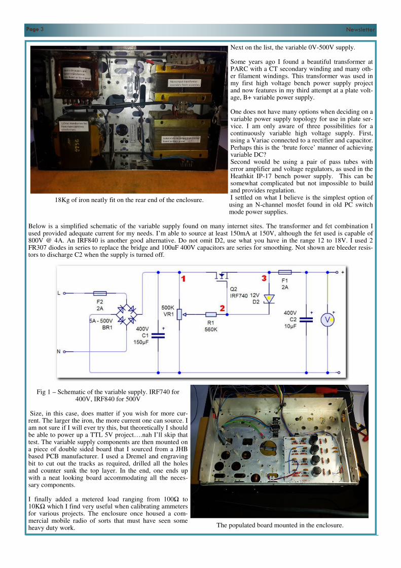
Next on the list, the variable 0V-500V supply. Some years ago I found a beautiful transformer at PARC with a CT secondary winding and many oth-er filament windings. This transformer was used in my first high voltage bench power supply project and now features in my third attempt at a plate volt-age, B+ variable power supply. One does not have many options when deciding on a variable power supply topology for use in plate ser-vice. I am only aware of three possibilities for a continuously variable high voltage supply. First, using a Variac connected to a rectifier and capacitor. Perhaps this is the ‘brute force’ manner of achieving variable DC? Second would be using a pair of pass tubes with error amplifier and voltage regulators, as used in the Heathkit IP-17 bench power supply. This can be somewhat complicated but not impossible to build and provides regulation. I settled on what I believe is the simplest option of using an N-channel mosfet found in old PC switch mode power supplies.
Below is a simplified schematic of the variable supply found on many internet sites. The transformer and fet combination I used provided adequate current for my needs. I’m able to source at least 150mA at 150V, although the fet used is capable of 800V @ 4A. An IRF840 is another good alternative. Do not omit D2, use what you have in the range 12 to 18V. I used 2 FR307 diodes in series to replace the bridge and 100uF 400V capacitors are series for smoothing. Not shown are bleeder resis-tors to discharge C2 when the supply is turned off.
Fig 1 – Schematic of the variable supply. IRF740 for 400V, IRF840 for 500V
Size, in this case, does matter if you wish for more cur-rent. The larger the iron, the more current one can source. I am not sure if I will ever try this, but theoretically I should be able to power up a TTL 5V project….nah I’ll skip that test. The variable supply components are then mounted on a piece of double sided board that I sourced from a JHB based PCB manufacturer. I used a Dremel and engraving bit to cut out the tracks as required, drilled all the holes and counter sunk the top layer. In the end, one ends up with a neat looking board accommodating all the neces-sary components. I finally added a metered load ranging from 100Ω to 10KΩ which I find very useful when calibrating ammeters for various projects. The enclosure once housed a com-mercial mobile radio of sorts that must have seen some heavy duty work.
18Kg of iron neatly fit on the rear end of the enclosure.
The populated board mounted in the enclosure.

Page 4 Newsletter
But after drilling and filing all the holes, a coat of spray paint made all the difference. In fact, the paint and 15A socket are the only items not found at any of the flea markets.
Testing the completed PSU and ready for some labelling.
Well there you have it, a homebrew power supply sourced almost entirely from flea market scoops. Thank you to all the clubs and organisers that host these events. Be rest assured of my patronage and I hope that this will inspire some of you to build something.
There’s nothing revolutionary about this power supply, but I can say that almost all of the components are bits and pieces
found at flea markets. PARC produced the enclosure a few years ago; WR the meters, capacitors and a few other fragments.
Gordon, at the East rand gathering, has wonderful terminals and switches, not to mention Hans’s lucky packet bins that always
produce desirable components that I know will be needed some day.
Some of the components even travelled from as far as Harrismith, and many of my buds have juicy inventories in their garages
- or know that I’m always after bits so keep an eye out for components, scrap boards, old gear etc. These “Agents” sniff out
parts and I’m delighted when the phone rings from my troops, I know a visit is due with an empty boot.
Page 5 Newsletter
A Simple RF Voltmeter
Subtitle:Subtitle:Subtitle:Subtitle: Something old and something new!Something old and something new!Something old and something new!Something old and something new!
Introduction When working with RF equipment the loading of the circuitry when measuring voltage can be a problem. In many cases the voltmeter might have a sensitivity of only 20kΩ per volt and this can cause incorrect readings if the circuit is high impedance, such as grid bias measurement. Although modern DVMs offer high input resistance for dc voltage they fall down when high frequency AC signals are applied as the rectifiers within them are limited to about 20kHz.
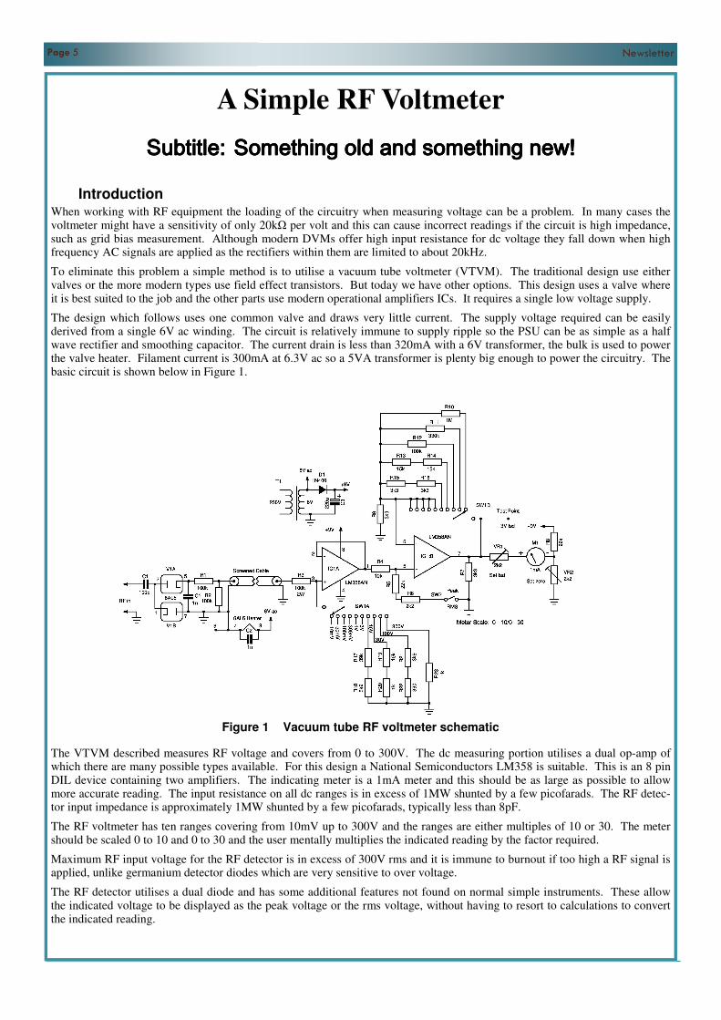
To eliminate this problem a simple method is to utilise a vacuum tube voltmeter (VTVM). The traditional design use either valves or the more modern types use field effect transistors. But today we have other options. This design uses a valve where it is best suited to the job and the other parts use modern operational amplifiers ICs. It requires a single low voltage supply.
The design which follows uses one common valve and draws very little current. The supply voltage required can be easily derived from a single 6V ac winding. The circuit is relatively immune to supply ripple so the PSU can be as simple as a half wave rectifier and smoothing capacitor. The current drain is less than 320mA with a 6V transformer, the bulk is used to power the valve heater. Filament current is 300mA at 6.3V ac so a 5VA transformer is plenty big enough to power the circuitry. The basic circuit is shown below in Figure 1.
Figure 1 Vacuum tube RF voltmeter schematic
The VTVM described measures RF voltage and covers from 0 to 300V. The dc measuring portion utilises a dual op-amp of which there are many possible types available. For this design a National Semiconductors LM358 is suitable. This is an 8 pin DIL device containing two amplifiers. The indicating meter is a 1mA meter and this should be as large as possible to allow more accurate reading. The input resistance on all dc ranges is in excess of 1MW shunted by a few picofarads. The RF detec-tor input impedance is approximately 1MW shunted by a few picofarads, typically less than 8pF.
The RF voltmeter has ten ranges covering from 10mV up to 300V and the ranges are either multiples of 10 or 30. The meter should be scaled 0 to 10 and 0 to 30 and the user mentally multiplies the indicated reading by the factor required.
Maximum RF input voltage for the RF detector is in excess of 300V rms and it is immune to burnout if too high a RF signal is applied, unlike germanium detector diodes which are very sensitive to over voltage.
The RF detector utilises a dual diode and has some additional features not found on normal simple instruments. These allow the indicated voltage to be displayed as the peak voltage or the rms voltage, without having to resort to calculations to convert the indicated reading.
Page 6 Newsletter
The various voltage ranges are catered for by a switch with ten positions. The ranges are amplified on the lower ranges and attenuated on the upper ranges. The range switch is a dual gang ten position wafer switch with some ranges using dc gain and the others using dc attenuation.
A front panel pot (VR2) allows the setting of the zero position and a second variable resistor (VR1) sets the full scale deflec-tion. (This variable resistor is inside the cabinet as it only will require adjusting if V1 is changed). The full scale deflection on the 3V range is set by VR1. Calibration requires a variable dc supply of 10V, thereafter all the other ranges should fall within 2%.
RF detector The RF detector is a separate item from the main unit and is connected by shielded cables with suitable plugs to the main unit. The RF head should be in a metal screened tube with a probe tip and a grounding lead. The connection between the RF head and the main unit should be via screened cable for both the dc output signal and the heater supply. The screen should be grounded at both ends.
The RF detector uses a dual diode as a full wave voltage doubler. The EB91 (6AL5) is a very low input capacitance valve, only 3.6pF per section. It will operate up to 700 MHz according to the GE data sheet and can detect signals as low as 10mV.
In order to reduce the contact potential, (which all valve rectifiers suffer from causing a small residual output voltage without an input signal), the heater is run at a lower voltage to reduce this effect. This is provided by the 6V transformer secondary rather than the normal 6.3V. It is also essential to connect pin 6 of the EB91 (6AL5) to ground as this is an internal shield to reduce coupling between the two diodes. RF grounding should be by very short leads.
The input capacitor C1 to the RF detector needs to be adequately rated for the voltage used, especially if the circuit being measured is powered by a high dc voltage. A 1kV mica or ceramic capacitor is recommended.
The output of the RF detector passes via an attenuator to reduce the detected voltage by a factor of two (provided by R1 / R2 in the RF head). The two diodes form a voltage doubler with an output dc voltage which is 2.828 times the rms input voltage. This makes measuring very low RF voltages easier. To convert the peak voltage obtained to the equivalent rms (only for a true sinusoidal input signal) a second switch (SW2) is used to apply an attenuator to the output signal of the first operational ampli-fier stage. The shunt resistor lowers the peak voltage to the rms voltage by switching into circuit R5 and R6 connected in se-ries. These with the 10kΩ series resistor (R4) give the rms value. If this function is not required these additional components can be omitted.
Main Unit The RF head connects to the main unit and supplies a dc voltage directly related to the RF input. To explain the workings of the unit first assume the RF head provides an output on the lowest range. This is 10mV fsd and as this is a very small voltage it is difficult to measure accurately. Hence, for the lowest ranges the signal is buffered by a voltage follower consisting of one half of the LM358 IC. The fsd of the metering section was chosen to be 3V dc for various reasons. To make the 10mV input signal equal to 3V dc requires amplification. This is performed by the second half of the LM358. It is a non-inverting amplifi-er where the gain is set by two resistors. The output of the IC is fed back to the inverting input and attenuated by the series resistor. For the 10mV range this is R10 (1MW) and with R9 it provides a gain of 300. The other lower ranges follow the same approach. The second range is 30mV and it requires a gain of 100 to bring it to 3V fsd.
The five lowest ranges have gain setting resistors to make the input equal to 3V. But from the 3V range upwards no gain is required and the range switch (SW1B) reconfigures the amplifier as a voltage follower with a gain of 1.
The first half of the range switch (SW1A) is also used to process the input signal from the RF head. For the ranges 10mV to 3V it is a normal voltage follower with a gain of 1. But for the upper ranges (10V to 300V) it serves to switch in various atten-uator networks to hold the dc output voltage to a maximum of 3V.
On the 10V range the signal needs to be reduced to 3V fsd and this is a ratio of 3 / 10 = 0.333:1. Resistor R3 in series is shunt-ed to ground by a resistor value to provide the correct ratio. As the shunt resistor value required is a non-standard value it is made up from two resistors connected in series. For the 10V range the shunt resistor required is 42.9kΩ and this consists of a 39kΩ and a 3k9Ω in series. The other higher ranges also have the same arrangement. On the 300V fsd range the divider ratio is 100:1.
These resistors and the series resistors for SW1B need to be close tolerance types and 2% tolerance metal film resistors of 1/4Ω is the best choice. The only resistor which needs a higher wattage rating is R3 (100kΩ) and a PRO-2 metal film resistor is the best choice. These are slightly bigger than a normal 1/2Ω resistor and can dissipate 2W.
The use of SW2 and resistors R5 / R6 convert the peak dc voltage to the rms voltage.
Construction Details The VTVM should be constructed in a metal case with all grounding points taken with minimum lead lengths to the case or chassis. Stray ac fields and RF can upset the working so attention to eliminating these will require adequate screening, filtering and decoupling of power cords etc. The printed circuit board (shown later) has a grounding track which connects all the
Page 7 Newsletter
ground points together. The board should be mounted on short metal pillars with M3 screws to provide an adequate low in-ductance ground.
The lead lengths of the RF detector should be as short as possible to eliminate stray inductance. The input probe should con-nect directly to the input blocking capacitor C1 with very short leads if the highest frequency of operation is desired.
The multi-pole wafer switch and the valve base (socket) for V1 should be ceramic or some other good insulator. Leakage cur-rents on these components can alter the readings and accuracy.
The choice of connectors can be BNC panel mount or as the constructor prefers. BNC is preferred as then normal ‘scope probes can be connected allowing simpler measurements. By disconnecting the RF head the main unit serves as an accurate dc voltmeter.
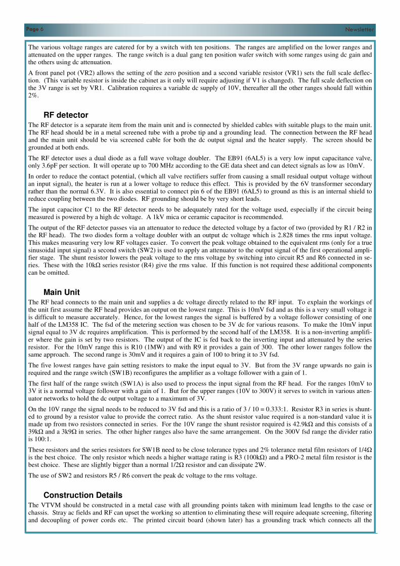
Printed circuit details are shown in Figure 2 & 3. The board is 83.8mm x 63.5mm (3.3” x 2.5”) and is single sided. As the printed copy will not be exactly correct it is necessary to ‘fine tune’ the dimensions using a photocopier. Print the bottom cop-per tracks and measure the board dimensions obtained. Adjust the copier ratio to bring it to the correct size. The pin spacing of IC1 is exactly 0.1” (2.54mm) by 0.3” (7.62mm).
Calibration Method To calibrate the dc ranges firstly ensure the meter is correctly zeroed by the mechanical adjuster, then switch on and ground the dc input to the main unit by disconnecting the RF head. Select the 10mV range and set the meter to zero with the zero set pot VR2. Allow at least 10 minutes for the unit to stabilise before attempting to set the calibration. The zero setting should be checked before any adjustment or measurement is made to ensure an accurate result.
Set the range switch to 10V. Connect a 10V dc voltage to the dc input connector. Connect an accurate voltmeter to the test point and ensure this reads 3.0V. Then adjust variable resistor VR1 to obtain full scale deflection on the meter. All the other ranges should now be within 2% or better of fsd for each range. By selecting another range, say 1V, and setting the dc supply to the same full scale voltage we can check the calibration. The accuracy is entirely defined by the tolerance of the resistors used in the attenuator and gain networks. With 2% resistors the accuracy at worst case will be ±4%.
To check the calibration of the RF detector requires a signal generator and a terminating resistor to suit the generator imped-ance. As most signal generators do not give more than +20dBm (100mW in 50Ω) this is a fairly small RF voltage. To check the calibration connect a 50Ω dummy load termination to one side of a BNC Tee piece and the signal generator to the other and connect to the RF detector. For example, an input of 100mW the rms voltage in 50Ω is 2.234V. Hence, 1.5V rms equates to 45mW in 50Ω and 1V peak indicated is 10mW.
Figure 2 Printed circuit board layout Viewed from bottom
Page 8 Newsletter
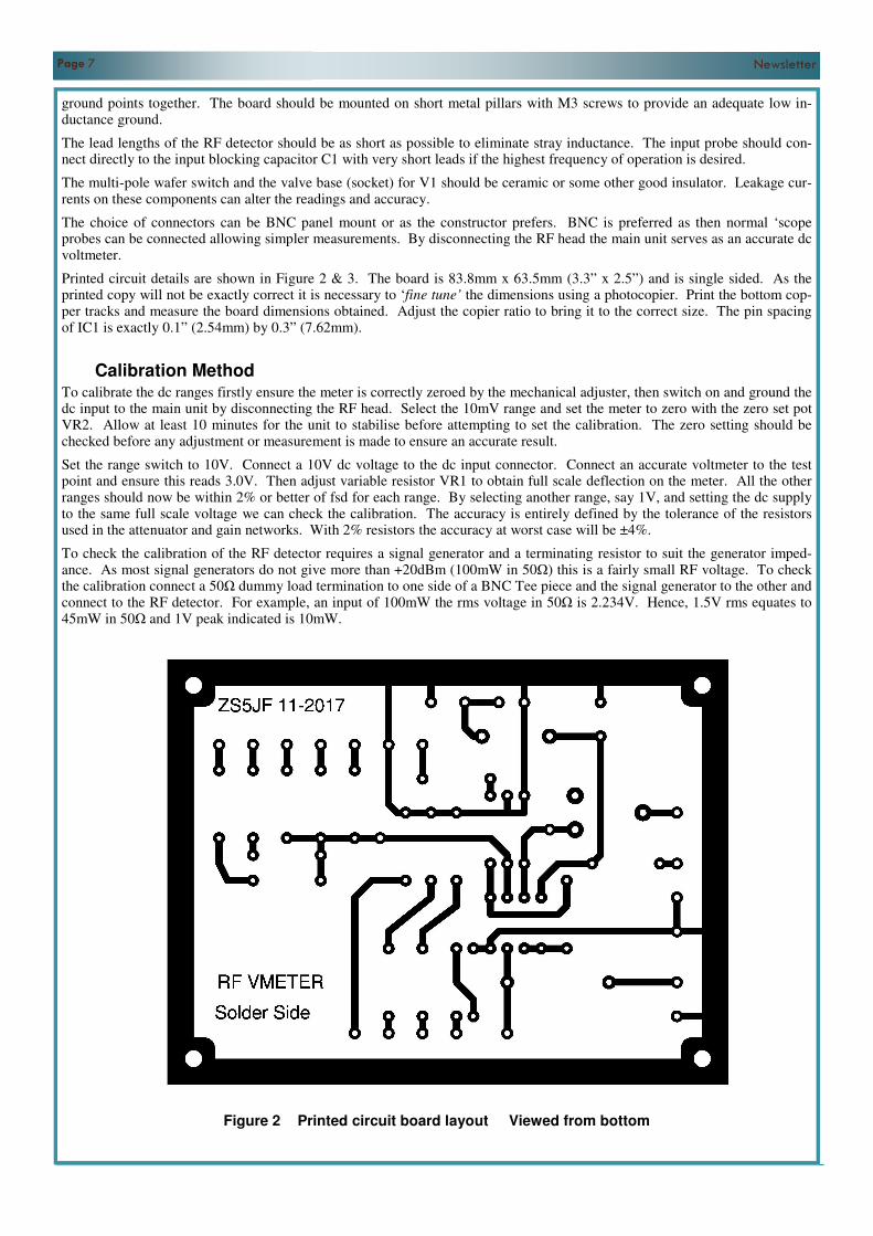
Figure 3 Component Layout Top view _______________________________________________________________________________________________
The Heathkit Challenge John ZS1WJ
As the new President of the AWA I would like to introduce a project whereby members of the AWA can get involved in the restoration of some of the really nostalgic radios of the 60’s & 70’s. For the majority of Hams of the 60’s & 70’s era, Heathkit was the be all of Amateur radio and it also taught those of us who could afford them the art of constructing your own station and getting the pleasure out of using it when completed. We learnt how to recognize components, use test equipment, layout of components, winding coils and most important of all HOW TO SOLDER. The project I envisage is to find and restore as many Heathkit HW-100, HW-101, SB-101 & SB-102 ‘s that we can find and bring them back to life. This can be done individually or in teams of two or three. The restoration will need to be documented ie; Start- photos of the rig as acquired- the rebuild with lots of photos and write ups – and the final product. The time frame for this project will be – completion by end August 2019, judging and testing during Sept/Oct 2019 and final results at the 2019 AGM. There will be two prizes 1st Place – R2000.00 2nd Place – R1000.00 We may however find that other Members and Organisations would like to come aboard and add to the prizes.
Page 9 Newsletter
RF Sampler and Demodulator RF Sampler and Demodulator RF Sampler and Demodulator RF Sampler and Demodulator
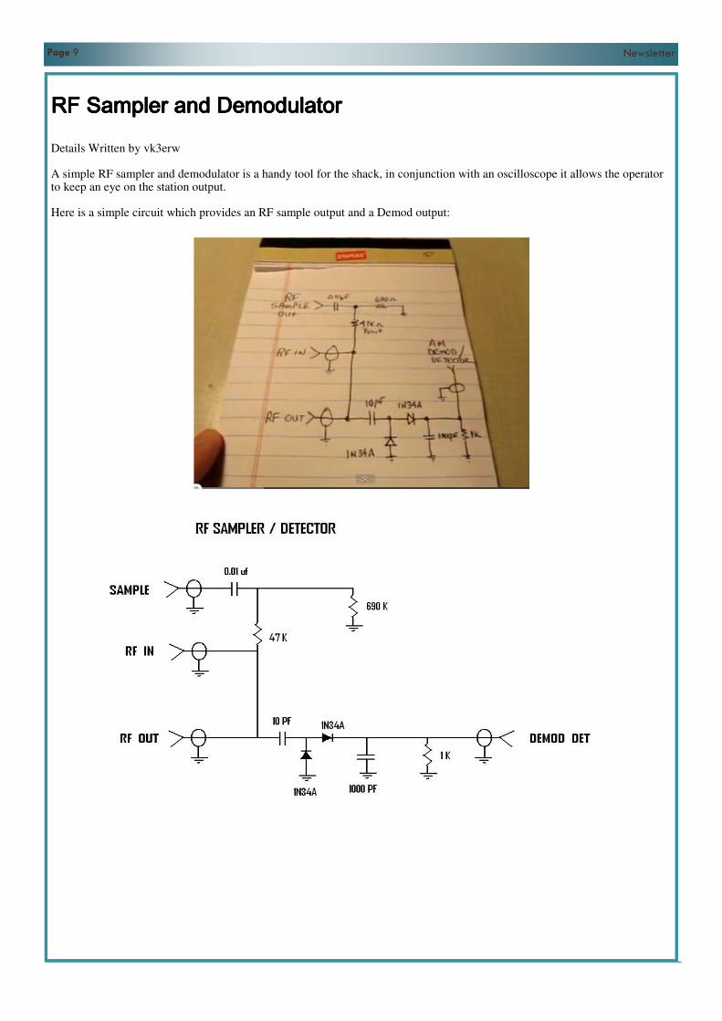
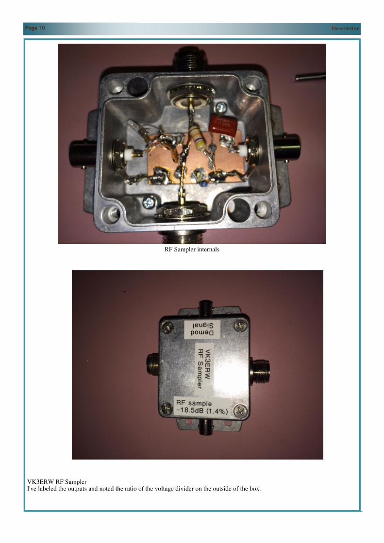
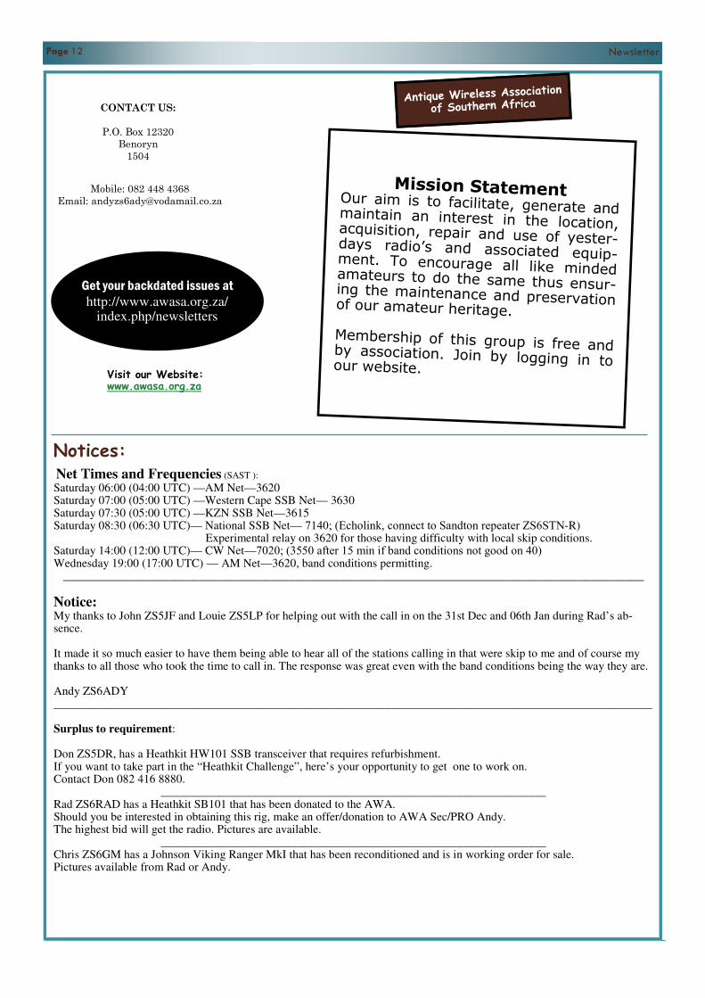
Details Written by vk3erw A simple RF sampler and demodulator is a handy tool for the shack, in conjunction with an oscilloscope it allows the operator to keep an eye on the station output. Here is a simple circuit which provides an RF sample output and a Demod output:
Page 10 Newsletter
RF Sampler internals
VK3ERW RF Sampler I've labeled the outputs and noted the ratio of the voltage divider on the outside of the box.

Page 11 Newsletter
Anque Wireless Associaon CW Acvity Day
1. Aim
The aim of the CW Acvity Day is for parcipants to contact as many amateurs as possible on the 20, 40 and
80 m amateur bands.
2. Date and Time
13:00 – 15:00 UTC (15:00—17:00 SAST) on Sunday 4 February 2018.
3. Frequencies
14 000 to 14 060 kHz; 7 000 to 7 040 kHz and 3 510 to 3 560 kHz
4. Categories
4.1 Single Operator All Band, Low Power (maximum 100 W)
4.2 Single operator All Band, QRP (maximum 5 W)
4.3 Single Operator Single Band, Low Power (maximum 100 W)
4.4 Single operator Single band, QRP (maximum 5 W)
5. Exchange
RST, operators name and Grid Square locator
6. Scoring
Contacts count 1 point for low power, 2 points for QRP.
7. Awards
Cerficates are awarded to the first places and the highest single band score.
8. Log Sheets
Log sheets must be submi&ed by Monday 20 February 2017 to [email protected]
Page 12 Newsletter
CONTACT US:
P.O. Box 12320
Benoryn
1504
Mobile: 082 448 4368
Email: [email protected]
Get your backdated issues at http://www.awasa.org.za/
index.php/newsletters
Visit our Website: www.awasa.org.za
Antique Wireless Association
of Southern Africa
Mission Statement Our aim is to facilitate, generate and maintain an interest in the location, acquisition, repair and use of yester-days radio’s and associated equip-ment. To encourage all like minded amateurs to do the same thus ensur-ing the maintenance and preservation of our amateur heritage. Membership of this group is free and by association. Join by logging in to our website.
Notices: Net Times and Frequencies (SAST ):
Saturday 06:00 (04:00 UTC) —AM Net—3620 Saturday 07:00 (05:00 UTC) —Western Cape SSB Net— 3630 Saturday 07:30 (05:00 UTC) —KZN SSB Net—3615 Saturday 08:30 (06:30 UTC)— National SSB Net— 7140; (Echolink, connect to Sandton repeater ZS6STN-R) Experimental relay on 3620 for those having difficulty with local skip conditions. Saturday 14:00 (12:00 UTC)— CW Net—7020; (3550 after 15 min if band conditions not good on 40) Wednesday 19:00 (17:00 UTC) — AM Net—3620, band conditions permitting.
__________________________________________________________________________________________________
Notice: My thanks to John ZS5JF and Louie ZS5LP for helping out with the call in on the 31st Dec and 06th Jan during Rad’s ab-sence. It made it so much easier to have them being able to hear all of the stations calling in that were skip to me and of course my thanks to all those who took the time to call in. The response was great even with the band conditions being the way they are. Andy ZS6ADY _____________________________________________________________________________________________________ Surplus to requirement: Don ZS5DR, has a Heathkit HW101 SSB transceiver that requires refurbishment. If you want to take part in the “Heathkit Challenge”, here’s your opportunity to get one to work on. Contact Don 082 416 8880.
_________________________________________________________________ Rad ZS6RAD has a Heathkit SB101 that has been donated to the AWA. Should you be interested in obtaining this rig, make an offer/donation to AWA Sec/PRO Andy. The highest bid will get the radio. Pictures are available.
_________________________________________________________________ Chris ZS6GM has a Johnson Viking Ranger MkI that has been reconditioned and is in working order for sale. Pictures available from Rad or Andy.