118-12 jenkins county k-12 section 23 0110 mechanical general provisions · 2015-09-02 · section...
TRANSCRIPT

118-12 Jenkins County K-12
School Code: 682-0117
MECHANICAL GENERAL PROVISIONS 23 0110 - 1
SECTION 23 0110
MECHANICAL GENERAL PROVISIONS
PART 1 - GENERAL
1.1 RELATED DOCUMENTS:
A. Drawings and general provisions of the Contract, including General and Special Conditions
and Division 1 Specification Sections, apply to this Section.
B. It is recognized that separate sub-contracts may be instituted by THIS CONTRACT'S
GENERAL CONTRACTOR with others. It is the responsibility of THIS CONTRACT'S
GENERAL CONTRACTOR to completely inform, coordinate and advise those sub-
contractors as to all of the requirements, conditions and information associated with
providing and installing their portion of the total job.
1.2 IMPOSED REGULATIONS:
A. Applicable provisions of the State and Local Codes and of the following codes and standards
in addition to those listed elsewhere in the specifications are hereby imposed on a general
basis for mechanical work. In each case, the prevailing edition shall be the current adopted
edition of the state where the project is located.
1. International Mechanical Code.
2. International Gas Code.
3. International Energy Conservation Code.
4. International Fire Code.
1.3 SCOPE OF WORK:
A. Provide all labor, materials, equipment and supervision to construct complete and operable
mechanical systems as indicated on the drawings and specified herein. All materials and
equipment used shall be new, undamaged and free from any defects.
1.4 EXISTING SERVICES AND FACILITIES:
A. Damage to Existing Services: Existing services and facilities damaged by the Contractor
through negligence or through use of faulty materials or workmanship shall be promptly
repaired, replaced, or otherwise restored to previous conditions by the Contractor without
additional cost to the Owner.
B. Interruption of Services: Interruptions of services necessary for connection to or modification
of existing systems or facilities shall occur only at prearranged times approved by the Owner.
Interruptions shall only occur after the provision of all temporary work and the availability of
adequate labor and materials will assure that the duration of the interruption will not exceed
the time agreed upon.
118-12 Jenkins County K-12
School Code: 682-0117
MECHANICAL GENERAL PROVISIONS 23 0110 - 2
C. Removed Materials: Existing materials made unnecessary by the new installation shall be
removed, shall remain the property of the Owner and shall be stored at a location and in a
manner as directed, or, if classified by the Owner's authorized representative as unsuitable for
further use, shall become the property of the Contractor and shall be removed from the site.
1.5 PRODUCT WARRANTIES:
A. Provide manufacturer's standard printed commitment in reference to a specific product and
normal application, stating that certain acts of restitution will be performed for the Purchaser
or Owner by the manufacturer, when and if the product fails within certain operational
conditions and time limits. Where the warranty requirements of a specific specification
section exceed the manufacturer's standard warranty, the more stringent requirements will
apply and modified manufacturer's warranty shall be provided. In no case shall the
manufacturer's warranty be less than one (1) year.
1.6 PRODUCT SUBSTITUTIONS:
A. General: Materials specified by manufacturer's name shall be used unless prior approval of
an alternate is given by addenda. Requests for substitutions must be received in the office of
the Architect at least 10 days prior to opening of bids.
PART 2 - PRODUCTS
2.1 GENERAL MECHANICAL PRODUCT REQUIREMENTS:
A. Standard Products: Provide not less (quality) than manufacturer's standard products, as
specified by their published product data. In addition to the indication that a particular
product/model number is acceptable, comply with the specified requirements. Do not assume
that the available off-the-shelf condition of a product complies with the requirements; as an
example, a specific finish or color may be required.
B. Uniformity: Where multiple units of a general product are required for the mechanical work,
provide identical products by the same manufacturer, without variations except for sizes and
similar variations as indicated.
C. Product Compatibility, Options: Where more than one product selection is specified, either
generically or proprietarily, selection is Purchaser's or Installer's option. Provide mechanical
adaptations as needed for interfacing of selected products in the work.
D. Equipment Nameplates: Provide a permanent operational data nameplate on each item of
power operated mechanical equipment, indicating the manufacturer, product name, model
number, serial number, speed, capacity, power characteristics, labels of tested compliance,
and similar essential operating data.
E. Locate nameplates in easy-to-read locations. When product is visually exposed in an
occupied area of the building, locate nameplate in a concealed position (where possible)
which is accessible for reading by service personnel.
118-12 Jenkins County K-12
School Code: 682-0117
MECHANICAL GENERAL PROVISIONS 23 0110 - 3
PART 3 - EXECUTION
3.1 PRODUCT INSTALLATION, GENERAL:
A. Except where more stringent requirements are indicated, comply with the product
manufacturer's installation instructions and recommendations, including handling, anchorage,
assembly, connections, cleaning and testing, charging, lubrication, startup, test operation and
shut-down of operating equipment. Consult with manufacturer's technical experts, for
specific instructions on unique product conditions and unforeseen problems.
B. Protection and Identification: Deliver products to project properly identified with names,
models numbers, types, grades, compliance labels and similar information needed for distinct
identifications; adequately packaged or protected to prevent deterioration during shipment,
storage and handling. Store in a dry, well ventilated, indoor space, except where prepared
and protected by the manufacturer specifically for exterior storage.
C. Permits and Tests: Provide labor, material and equipment to perform all tests required by the
governing agencies and submit a record of all tests to the Owner or his representative. Notify
the Architect five days in advance of any testing.
END OF SECTION 23 0110

118-12 Jenkins County K-12
School Code: 682-0117
MECHANICAL STANDARDS 23 0120 - 1
SECTION 23 0120
MECHANICAL STANDARDS
PART 1 - GENERAL
1.1 RELATED DOCUMENTS:
A. Drawings and general provisions of the Contract, including General and Special Conditions
and Division 1 Specification Sections, apply to this Section.
1.2 QUALITY ASSURANCE:
A. Industry Standards: It is a general requirement that mechanical work comply with applicable
requirements and recommendations of standards published by listed agencies and trade
associations, except to the extent more detailed and stringent requirements are indicated or
required by governing regulations.
B. Listing of Associations, Standards, and Abbreviations:
1. AGA American Gas Association
1515 Wilson Blvd.
Arlington, VA 22209
2. AMCA Air Movement & Control Association
30 W. University Dr., Arlington Heights, IL 60004
302/394-0150
3. ARI Air-Conditioning and Refrigeration Institute
4301 North Fairfax Drive, Suite 425, Arlington, VA
22203
703/524-8800
4. ASHRAE American Society of Heating, Refrigerating &
Air Conditioning Engineers, Inc.
1791 Tullie Circle, NE, Atlanta, GA. 30329
404/636-8400
5. AWS American Welding Society, Inc.
2501 NW 7th St., Miami, FL 33125
305/642-7090
6. CISPI Cast Iron Soil Pipe Institute
2020 K. St., NW, Washington, DC
202/233-4536
7. NEBB National Environmental Balancing Bureau
1611 North Kent St.,
Arlington, VA 22209
8. NEC National Electrical Code by NFPA
9. NEMA National Electrical Manufacturers Association
1300 N 17th Street, Suite 1847
Rosslyn, VA 22209
703/841-3200
10. NFPA National Fire Protection Association

118-12 Jenkins County K-12
School Code: 682-0117
MECHANICAL STANDARDS 23 0120 - 2
407 Atlantic Ave.,
Boston, MA 02210
617/482-8755
11. SMACNA Sheet Metal & Air Conditioning Contractors National
Association, Inc.
8224 Old Courthouse Rd., Tysons Corner
Vienna, VA 22180
703/790-9890
12. TIMA Thermal Insulation Manufacturers Association
7 Kirby Plaza
Mt. Kisco, NY 10549
912/241-2284
13. UL Underwriters' Laboratories, Inc.
207 East Ohio St.,
Chicago, IL 60611
312/642-6969
PARTS 2 AND 3 - PRODUCTS AND EXECUTION
A. Not applicable,
END OF SECTION 23 0120

118-12 Jenkins County K-12
School Code: 682-0117
MECHANICAL COORDINATION 23 0210 - 1
SECTION 23 0210
MECHANICAL COORDINATION
PART 1 - GENERAL
1.1 RELATED DOCUMENTS:
A. Drawings and general provisions of the Contract, including General and Special Conditions
and Division 1 Specification Sections, apply to this Section.
1.2 QUALITY ASSURANCE:
A. Coordinate the actual location of all mechanical work visible in finished spaces with the
Architect/Engineer. This includes air distribution devices, exposed ductwork, thermostats,
humidistats, switches, sensors, etc.
PART 2 - PRODUCTS
2.1 MECHANICAL PRODUCT COORDINATION:
A. Power Characteristics: Refer to the electrical sections of the specifications and the electrical
drawings for the power characteristics available for the operation of each power driven item
of equipment. The electrical design was based on the typical power requirements of the
equipment manufacturers scheduled or specified. Any modifications to the electrical system
which are required due to the use of an approved equivalent manufacturer shall be made at no
additional cost to the owner. All changes must be clearly documented and submitted for
review by the Architect/Engineer prior to purchasing equipment. Coordinate purchases to
ensure uniform interface with electrical work. The mechanical contractor shall furnish a
detailed list of equipment electrical characteristics to the electrical contractor for the purpose
of preparing the coordination affidavit required by Division 26.
B. Coordination of Options and Substitutions: Where the contract documents permit the
selection from several product options, and where it becomes necessary to authorize a
substitution, do not proceed with purchasing until coordination of interface of equipment has
been checked and satisfactorily established.
C. Firestopping: Refer to architectural drawings for the locations of all fire rated ceilings, floors
and walls. The contractor shall furnish detailed shop drawings of all firestopping details to be
used for both piping and ductwork. All firestopping details shall be U.L. listed and subject to
approval by the Authority having jurisdiction.
PART 3 - EXECUTION

118-12 Jenkins County K-12
School Code: 682-0117
MECHANICAL COORDINATION 23 0210 - 2
3.1 INSPECTION AND PREPARATION:
A. Substrate Examination: The Installer of each element of the mechanical work must examine
the condition of the substrate to receive the work, and the conditions under which the work
will be performed, and must notify the Contractor in writing of conditions detrimental to the
proper completion of the work. Do not proceed with the work until unsatisfactory conditions
have been corrected in a manner acceptable to the Installer.
B. Do not proceed with the installation of sleeves, anchors, hangers, roof penetrations and
similar work until mechanical coordination drawings have been processed and released for
construction. Where work must be installed prior to that time in order to avoid a project
delay, review proposed installation in a project coordination meeting including all parties
involved with the interfacing of the work.
3.2 CUTTING AND PATCHING:
A. Structural Limitations: Do not cut structural framing, walls, floors, decks and other members
intended to withstand stress, except with the Architect's or Engineer's written authorization.
B. Where authorized, cut opening through concrete (for pipe penetrations and similar services)
by core drilling or sawing. Do not cut by hammer-driven chisel or drill.
C. Other work: Do not endanger or damage other work through the procedures and processes of
cutting to accommodate mechanical work. Review the proposed cutting with the Installer of
the work to be cut, and comply with his recommendations to minimize damage. Where
necessary, engage the original Installer or other specialists to execute the cutting in the
recommended manner.
D. Where patching is required to restore other work, because of either cutting or other damage
inflicted during the installation of mechanical work, execute the patching in the manner
recommended by the original Installer. Restore the other work in every respect, including the
elimination of visual defects in exposed finishes, as judged by the Architect. Engage the
original Installer to complete patching of the following categories of work:
1. Exposed concrete finishes and exposed masonry.
2. Waterproofing and vapor barriers.
3. Roofing, flashing and accessories.
4. Interior exposed finishes and casework, where judged by the Architect to be difficult to
achieve an acceptable match by other means.
3.3 COORDINATION OF MECHANICAL INSTALLATION:
A. General: Sequence, coordinate and integrate the various elements of mechanical work so that
the mechanical plant will perform as indicated and be in harmony with the other work of the
building. The Architect/Engineer will not supervise the coordination, which is the exclusive
responsibility of the Contractor. Comply with the following requirements:
1. Install piping, ductwork and similar services straight and true, aligned with other work
and with overhead structures and allowing for insulation. Conceal where possible.

118-12 Jenkins County K-12
School Code: 682-0117
MECHANICAL COORDINATION 23 0210 - 3
2. Arrange work to facilitate maintenance and repair or replacement of equipment. Locate
services requiring maintenance on valves and similar units in front of services requiring
less maintenance. Connect equipment for ease of disconnecting, with minimum of
interference with other work.
3. Equipment located above ceilings shall be installed in a position and elevation which
allows complete and adequate maintenance access through the ceiling grid or access
panel while standing safely on a ladder. If this is not possible, a suitable maintenance
platform must be provided per IMC.
4. Give the right-of way to piping systems required to slope for drainage (over other service
lines). Piping shall be located to avoid interference with ductwork and light fixtures.
5. Store materials off the ground and protected from standing water and weather.
B. Drawings: Conform with the arrangement indicated by the contract documents to the greatest
extent possible, recognizing that portions of the work are shown only in diagrammatic form.
Where coordination requirements conflict with individual system requirements, comply with
the Architect's decision on resolution of the conflict.
C. Electrical Work: Coordinate the mechanical work with electrical work, and properly
interface with the electrical service. In general, and except as otherwise indicated, install
mechanical equipment ready for electrical connection. Refer to electrical sections of the
specifications for electrical connection of mechanical equipment.
D. Duct Smoke Detectors: All HVAC duct smoke detectors, including smoke detectors for
smoke dampers, shall be furnished by Division 26 and installed by Division 23. In buildings
equipped with a fire alarm system, all duct smoke detectors must be compatible with the fire
alarm system and must be connected to the fire alarm system for notification. All fire alarm
wiring and associated devices shall be furnished and installed by the fire alarm system
installer. Each smoke detector shall be wired into the respective fan control circuit to
automatically shut down the fan upon sensing products of combustion.
E. Utility Connections: Coordinate the connection of mechanical systems with exterior
underground utilities and services. Comply with the requirements of governing regulations,
franchised service companies and controlling agencies. Provide a single connection for each
service except where multiple connections are indicated.
3.4 COORDINATION OF MECHANICAL START-UP:
A. Seasonal Requirements: Adjust and coordinate the timing of mechanical system start-ups
with seasonal variations, so that demonstration and testing of specified performance can be
observed and recorded. Exercise proper care in off-season start-ups to ensure that systems
and equipment will not be damaged by the operation.
B. Painting and Air Distribution: Coordinate the initial cleaning and start-up of the air
distribution system, to occur prior to preparatory cleaning and general interior painting and
decorating on the project. The HVAC system should not be operated until drywall work is
completed. Drywall dust must not be allowed to contaminate the interior of air handing units
and ductwork. Use high efficiency temporary filters until project closeout.
END OF SECTION 23 0210
118-12 Jenkins County K-12
School Code: 682-0117
MECHANICAL SUBMITTALS 23 0220 - 1
SECTION 23 0220
MECHANICAL SUBMITTALS
PART 1 - GENERAL
1.1 RELATED DOCUMENTS:
A. Drawings and general provisions of the Contract, including General and Special Conditions
and Division 1 Specification Sections, apply to this Section.
1.2 SUBMITTAL FORMS AND PROCEDURES:
A. The purpose of submittals is to demonstrate to the Architect/Engineer that the Contractor
understands the design concept. The Architect/Engineer's review of such drawings,
schedules, or cuts shall not relieve the Contractor from responsibility for deviation from
drawings or specifications unless he has, in writing, called the Architect/Engineer's attention
to such deviations at the time of submission, and has received from the Architect/Engineer, in
writing, permission for such deviations. All submittals must be completely checked by the
Contractor prior to submission for review.
B. Hard Copy Submittals: Submittal data shall be placed in one or more hard-back 3-ring
binders, arranged and labeled according to specification section. Each binder shall contain a
title page and table of contents. Provide separator tabs, and label by specification section.
Make note in the table of contents, any drawings that accompany the submittal. Title page
shall contain Project Name, Contractor’s Name, Division 23 Superintendent’s name,
Suppliers and point of contact for each, and date. Except as otherwise indicated in other
sections, submit 5 complete copies. Quantity indicated does not include copies required for
regulatory agencies.
C. Electronic Submittals: If the Architect agrees to allow electronic submittals via an on-line
information management product such as “Submittal Exchange,” etc., all electronic submittal
files shall be organized to match the bid documents for specification section and name. Each
submittal file shall be complete for each specification section. Multiple partial submittals per
specification section will be rejected. Make note in the table of contents, any drawings that
accompany the submittal. Title page shall contain Project Name, Contractor’s Name,
Division 23 Superintendent’s name, Suppliers and point of contact for each, and date.
D. Submittals shall be made for all items contained in the following specification sections:
1. Mechanical Identification
2. Mechanical Pipe, Tube, and Fittings
3. Mechanical Hangers and Supports
4. Ductwork and Accessories
5. Air Distribution
6. Fans
7. Kitchen Hood Ventilation System
8. Dust Collection System
9. Welding Exhaust System

118-12 Jenkins County K-12
School Code: 682-0117
MECHANICAL SUBMITTALS 23 0220 - 2
10. Electric Heaters
11. Air Treatment Systems
12. Air Conditioners
13. Heat Pumps
14. Energy Recovery Ventilators
15. HVAC Control System
16. Mechanical Sound, Vibration, Wind and Seismic Control
17. Mechanical Testing, Adjusting, Balancing
18. Mechanical Commissioning
E. Response to Submittals: A Submittal Review Report shall be issued by the
Architect/Engineer with the following classifications for each item:
1. "No Exceptions Taken": No corrections, no marks. Contractor shall submit copies for
distribution.
2. "Make Corrections Noted": A few minor corrections. Items may be ordered as
marked up without further resubmission. Submit copies for distribution.
3. "Revise and Resubmit": Minor corrections. Item may be ordered at the Contractor's
option. Contractor shall resubmit drawings with corrections noted.
4. "Rejected": Major corrections or not in accordance with the contract documents. No
items shall be ordered. Contractor shall correct and resubmit drawings.
PART 2 - PRODUCTS
2.1 SUBMITTAL REQUIREMENTS:
A. General: Each specification section shall list the required submittal items. All submittal
items shall conform to the requirements listed below. For each major section of submittal
data, include a summary page which lists items and model numbers for each piece of
equipment.
B. Shop Drawings: Prepare mechanical shop drawings to accurate scale except where
diagrammatic representations are specifically indicated. Show clearance dimensions of
critical locations, and show dimensions of spaces required for operation and maintenance of
equipment. Show piping connections and other service connections, and show interface with
other work including structural support. Indicate by note, the portions of mechanical work
shown on the shop drawings which deviated from the indication of work in the contract
documents, and explain the reasons for the deviations. Show how such deviations coordinate
with interfacing deviations on shop drawings for other portions of the work, currently or
previously submitted.
C. Manufacturer's Data: Where pre-printed data is submitted for more than one distinct product,
size, type, material, trim, accessory group or other variation, mark submitted copy with black
pen to indicate which of the variations is to be provided. Delete or mark-out significant
portions of preprinted data which are not applicable. Where operating ranges are shown,
mark data to show portion of range required for project application. Expansion or elaboration
of standard data to describe a non-standard product must be processed as a shop drawing
submittal. For each product include the manufacturer's production specifications, installation
or fabrication instructions, nearest source of supply (including telephone number), sizes,
weights, speeds, operating capacities, piping and service line connection sizes and locations,
118-12 Jenkins County K-12
School Code: 682-0117
MECHANICAL SUBMITTALS 23 0220 - 3
statements of compliance with required standards and governing regulation (include
manufacturer's signed statements if not covered in printed data), performance data (where
applicable) and similar information needed to confirm compliance with the requirements.
D. Certifications: Where specifically indicated, submit with notarized execution.
E. Test Reports: Submit test reports which have been signed and dated by the firm performing
the test and prepared in the manner specified in the standard or regulation governing the test
procedures as indicated.
F. Manufacturer's Product Warranties: Where pre-printed and published warranty includes
substantial deviation from required warranty (as judged by the Architect or Engineer),
product is automatically disqualified from use on the project, except where manufacturer
prepares and issues a specific product warranty on the product, stating that it is in lieu of the
published warranty, and is executed by an authorized officer, and complies with the
requirements. Warranties shall comply with the requirements of individual specification
section where those requirements exceed the manufacturer's standard warranty.
PART 3 - EXECUTION
3.1 CLOSEOUT REQUIREMENTS:
A. Operating Instructions: Submit manufacturer's operating instructions for each item of
mechanical equipment and supplement with additional project application instructions where
necessary. Prepare and submit specific operating instructions for charging, start-up, control
or sequencing of operation, phase or seasonal variations, shut-down, safety and similar
operational instructions. Prepare in typewritten form in completely explained and easily
understood English language.
B. Maintenance Manuals: Organize each copy of the required system maintenance manuals to
include an index followed by thumb-tab marked sections for each of the following:
1. System operating instructions.
2. Emergency instructions including addresses and telephone numbers of service sources.
3. Regular system maintenance procedures including lubrication.
4. Spare parts listing and stocking recommendations.
5. Inspection, adjusting, rebalancing, cleaning, parts replacement, and similar maintenance
instructions and recommendations, including the proper use of tools and accessories.
6. Valve schedule and control diagram for each system.
7. Manufacturer's data for each operating item in each system.
8. Manufacturer's product warranties and guarantees relating to the system and equipment
items in the system.
9. Corrected or approved issues of submittal items relating to the system.
10. Bind each maintenance manual in one or more vinyl-covered, 2", 3-ring binder, plus
pocket-folder type binders for folded drawings, and mark the back spine of each binder
with system identification and volume number.
C. Maintenance Materials: Deliver to Owner’s representative at the location as directed, in
containers or packages suitable for storage and fully identified.

118-12 Jenkins County K-12
School Code: 682-0117
MECHANICAL SUBMITTALS 23 0220 - 4
D. Guarantees: Where indicated as "Certified", provide guarantee which, in addition to
execution by an authorized officer of each guarantor, is attested to by the Secretary of each
guarantor and bears the corporate seal.
END OF SECTION 23 0220
118-12 Jenkins County K-12
School Code: 682-0117
MECHANICAL IDENTIFICATION 23 0230 - 1
SECTION 23 0230
MECHANICAL IDENTIFICATION
PART 1 - GENERAL
1.1 RELATED DOCUMENTS:
A. Drawings and general provisions of the Contract, including General and Special Conditions
and Division 1 Specification Sections, apply to this Section.
1.2 QUALITY ASSURANCE:
A. Manufacturers: Firms regularly engaged in the manufacture of identification systems
required for this product.
B. Submittals: Submit manufacturer's data on materials and submit a sample of each type
required.
PART 2 - PRODUCTS
2.1 MECHANICAL IDENTIFICATION MATERIALS:
A. Engraved Plastic-Laminate Signs:
1. General: Provide engraving stock melamine plastic laminated, complying with FS L-
P-387, in the sizes and thicknesses indicated, engraved with engraver's standard letter
style of the sizes and wording indicated, black with white core, letter color, except as
otherwise indicated, punched for mechanical fastening except where adhesive mounting
is necessary because of substrate.
2. Thickness: 1/16 inch, except as otherwise indicated.
3. Fasteners: Self-tapping stainless steel screws, except contact type permanent adhesive
where screws cannot or should not penetrate the substrate.
2.2 LETTERING AND GRAPHICS:
B. General: Coordinate names, abbreviations and other designations used in the mechanical
identification work, with the corresponding designations shown, specified or scheduled.
Provide numbers, lettering recommended by manufacturers or as required for proper
identifications and operation/maintenance of the mechanical systems and equipment.
C. Multiple Systems: Where multiple systems of the same generic name are shown and
specified, provide identification which indicates the individual system number as well as the
service; as examples, Heat Pump No. HP-1, Exhaust Fan No. EF-1.

118-12 Jenkins County K-12
School Code: 682-0117
MECHANICAL IDENTIFICATION 23 0230 - 2
PART 3 - EXECUTION
3.1 APPLICATION AND INSTALLATION:
A. Coordination: Where identification is to be applied to surfaces which require insulation,
painting and other covering or finish, install identification after completion of covering or
painting.
B. Mechanical Equipment Identification: Install an engraved plastic laminate sign on or near
each major item of mechanical equipment and each operational device, as specified herein if
not otherwise specified for each item or device. Provide signs for all major items of
mechanical equipment.
END OF SECTION 23 0230

118-12 Jenkins County K-12
School Code: 682-0117
MECHANICAL WORK CLOSEOUT 23 0240 - 1
SECTION 23 0240
MECHANICAL WORK CLOSEOUT
PART 1 - GENERAL
1.1 RELATED DOCUMENTS:
A. Drawings and general provisions of the Contract, including General and Special Conditions
and Division 1 Specification Sections, apply to this Section.
1.2 DOCUMENTATION PROCEDURES:
A. Signed Commitments: Do not proceed with transfer of mechanical plant to the Owner for
operation until warranties, performance certifications and similar commitments to be signed
by Contractor and other entities have been executed and transmitted to Architect (for Owner's
records).
1.3 RECORD DRAWINGS:
A. Explanation: Except where otherwise indicated, mechanical drawings (contract drawings)
prepared by Architect/Engineer, contract/drawings, are diagrammatic in nature and may not
show locations accurately for various components of mechanical systems. Shop drawings,
including coordination drawings, prepared by Contractor shall show certain portions of work
more accurately to scale and location, and in greater detail.
B. General Recording Procedure: Maintain a white-print set, blue-line or black-line, of
mechanical contract drawings and shop drawings in clean, undamaged condition, for mark-up
of actual installations which vary substantially from the work as shown. Mark-up whatever
drawings are most capable of showing the installed conditions accurately; however, where
shop drawings are marked, record a reference note on appropriate contract drawing. Mark
with erasable pencil and use multiple colors to aid in the distinction between work of separate
mechanical systems. In general, record every substantive installation of mechanical work
which previously is either not shown or shown inaccurately, but in any case record the
following:
1. Aboveground piping, both exterior and interior, drawn to scale and fully dimensioned.
2. “Mechanical Project Record" shall be maintained as part of the "Project Record"
specified in Division 1.
PART 2 – PRODUCTS
2.1 NOT APPLICABLE:
PART 3 - EXECUTION

118-12 Jenkins County K-12
School Code: 682-0117
MECHANICAL WORK CLOSEOUT 23 0240 - 2
3.1 CLOSEOUT PROCEDURES:
A. General Coordination: Sequence closeout procedures properly, so that work will not be
endangered or damaged, and so that every required performance will be fully tested and
demonstrated.
B. System Performance Test Run: At the time of mechanical work closeout, check each item in
each system to determine that it is set for proper operation. With Owner's representative and
Architect/Engineer present, operate each system in a test run of appropriate duration to
demonstrate compliance with performance requirements. During or following test runs, make
final corrections or adjustments of system to refine and improve performances wherever
possible, including noise and vibration reductions, elimination of hazards, better response of
controls, signals and alarms, and similar system performance improvements. Provide testing
or inspection devices as may be requested for Architect's/Engineer's observation of actual
system performances. Demonstrate that controls and items requiring service or maintenance
are accessible. Test run shall be scheduled to coincide with Engineer's final inspection of the
mechanical work.
C. Cleaning and Lubrication: After final performance test run of each mechanical system, clean
system both externally and internally. Clean dirt and debris from air handling systems and
install new filters. Flush piping system by operating drains and similar means, and clean
strainers and traps. Lubricate both power and hand operated equipment and remove excess
lubrication. Touch-up minor damage to factory painted finishes and other painting specified
as mechanical work; refinish work where damage is extensive.
D. General Operating Instructions: In addition to specified training of Owner's operating
personnel specified in individual mechanical sections, and in addition to preparation of
written operating instructions and compiled maintenance manuals specified, provide general
operating instructions for the total mechanical plant. Conduct a walk-through explanation
and demonstration for orientation and education of Owner's personnel to be involved in
continued operation of building and its mechanical plant.
1. Describe each basic mechanical system and how its control system functions, including
flow adjustments, temperature control and similar operations.
2. Explain and point out identification system, displayed diagrams, signals, alarms and
similar provisions of the work.
3. Describe basic sequencing requirements and interlock provisions for system start-up,
phasing, coast-down, shut-down and seasonal operations.
4. Emphasize emergency procedures and safety provisions for protection of equipment and
safety of occupants during equipment malfunction, disasters, power failures and similar
unusual circumstances, and describe system limitations and precautions including
weather adjustments.
5. Outline basic maintenance procedures.
E. Demonstrate what adjustments have been made and can continue to be made to reduce noise
and vibration, improve system output, decrease energy consumption and similar performance
improvements.
F. Point out operational security provisions, safety, unavoidable hazards and similar operator
limitations. Display and conduct a "thumb-through" explanation of maintenance manuals,

118-12 Jenkins County K-12
School Code: 682-0117
MECHANICAL WORK CLOSEOUT 23 0240 - 3
record drawings, meter readings and similar service items.
G. Construction Equipment: After completion of performance testing and Owner's operating
instructions and demonstrations, remove installers tools, test facilities, construction
equipment and similar devices and materials used in execution of the work but not
incorporated in the work.
3.2 CONTINUED SYSTEM OPERATIONS:
A. Final Acceptance: At time of substantial completion of mechanical work, Owner's operating
personnel will take over operation of mechanical systems. However, until time of final
acceptance, respond promptly with consultation and services on whatever operation or
maintenance problems may remain or arise in continued operation of mechanical plant.
END OF SECTION 23 0240
118-12 Jenkins County K-12
School Code: 682-0117
MECHANICAL PIPE, TUBE AND FITTINGS 23 0310 - 1
SECTION 23 0310
MECHANICAL PIPE, TUBE AND FITTINGS
PART 1 - GENERAL
1.1 RELATED DOCUMENTS:
A. Drawings and general provisions of the Contract, including General and Special Conditions
and Division 1 Specification Sections, apply to this Section.
1.2 QUALITY ASSURANCE:
A. Industry Standards:
1. Qualify welding procedures, welders and operators in accordance with ASME B31.1 for
shop and project site welding of piping work.
2. Certify welding of piping work using the Standard Procedure Specifications by, and
welders tested under supervision of, the National Certified Pipe Welding Bureau.
B. SUBMITTALS:
1. Submit manufacturer's data, welding certifications, test reports, and product warranties as
applicable for all piping materials.
PART 2 - PRODUCTS
2.1 PIPING MATERIALS:
A. General: Provide pipe and tube of the type, joint type, grade, size and weight (wall thickness
or Class) indicated for each service. Where type, grade or class is not indicated, provide
proper selection as determined by Installer for installation requirements and comply with
governing regulations and industry standards.
B. Copper Tube: ASTM B88-89 Type with wall thickness as recommended by equipment
manufacturer, except as otherwise indicated.
C. Plastic Pipe: PVC-WATER: ASTM D2466-88
2.2 PIPE/TUBE FITTINGS:
A. General: Provide factory-fabricated fittings of the type, materials, grade, class and pressure
rating indicated for each service and pipe size. Provide sizes and types matching pipe, tube
valve or equipment connections in each case. Where not otherwise indicated, comply with
governing regulations and industry standards for selections, and with pipe manufacturer's
recommendations where applicable.
118-12 Jenkins County K-12
School Code: 682-0117
MECHANICAL PIPE, TUBE AND FITTINGS 23 0310 - 2
B. Soldering Materials: Except as otherwise indicated, provide soldering materials as
determined by the Installer to comply with installation requirements.
1. Tin-Antimony Solder: ASTM B 32, Grade 95TA.
C. Solvent Cement for PVC Joints: D2564-88.
D. Pipe Sleeves:
1. Iron Pipe Sleeves: Fabricate from Schedule 40 galvanized steel pipe; remove burrs.
2. Sheet Metal Pipe Sleeves: Fabricate from galvanized sheet metal closed with lock-seam
joints. For following pipe sizes provide gauge indicated: 3 inch pipe and smaller, 20
gauge; 4 to 6 inch pipe, 16 gauge; over 6 inch pipe, 14 gauge.
3. Pipe Sleeve Caulking: 3M Fire Barrier Caulk, CP25N/S, or equal by STI or Grabber.
PART 3 - EXECUTION
3.1 INSTALLATION:
A. General: Install pipe, tube and fittings in accordance with recognized industry practices
which will achieve permanently-leakproof piping systems, capable of performing each
indicated service without piping failure. Install each run with a minimum of joints and
couplings, but with adequate and accessible unions for disassembly and maintenance/
replacement of valves and equipment. Reduce sizes (where indicated) by use of reducing
fittings. Align piping accurately at connections, within 1/16" misalignment tolerance.
1. Comply with ASME B31.1 Code for Pressure Piping.
B. Locate piping runs as indicated on the drawings. Route vertically and horizontally (pitched to
drain) and avoid diagonal runs wherever possible. Orient horizontal runs parallel with walls
and column lines. Locate runs as shown, or described by diagrams, details and notations or,
if not otherwise indicated, run piping in the shortest route which does not obstruct usable
space or block access for servicing the building and its equipment. Where possible, locate
insulated piping for 1.0" clearance outside insulation. Changes in direction shall be made
with fittings.
C. Piping System Joints: Provide joints of the type indicated in each piping system.
D. Soldered Joints: Solder copper tube and fitting joints where required, in accordance with
recognized industry practice. Cut tube ends squarely, ream to full inside diameter, and clean
outside of tube ends and inside of fittings with steel wool. Apply solder flux to joint areas of
both tubes and fittings. Insert tube full depth into fitting and solder in manner which will
draw solder full depth and circumference of joint. Wipe excess solder from joint before it
hardens. Use a non-corrosive paste flux and wire solder composed of 95 percent tin and 5
percent antimony.
E. Plastic Pipe/Tube Joints: Comply with manufacturer’s instructions and recommendations and
with applicable industry standards.
118-12 Jenkins County K-12
School Code: 682-0117
MECHANICAL PIPE, TUBE AND FITTINGS 23 0310 - 3
F. Pipe Sleeves: Install pipe sleeves of the types specified wherever piping passes through the
walls, floors or structural members of the work. Provide sleeves of adequate size, accurately
centered in pipe runs. Size sleeves so that piping and insulation will have free movement in
the sleeve, including allowance for thermal expansion. Where insulation includes a vapor
barrier covering provide sleeve with sufficient clearance for installation of vapor barrier.
Install length of sleeve equal to thickness of construction penetrated, except extend floor
sleeves 0.25 inches above floor finish. Provide temporary support of sleeves during
placement of concrete and other work around sleeves and provide temporary closure to
prevent concrete and other materials from entering pipe sleeves.
1. Sleeve Type: At interior partitions and ceilings, install sheet metal sleeves.
2. Sleeve Type: At exterior penetrations both above and below grade, install iron pipe
sleeves.
3. Sleeve Type: Except as otherwise specified, install steel pipe sleeves.
4. Caulk pipe sleeves at exterior penetrations and at other locations where indicated.
Provide sufficient quantities of oakum and lead to make permanent weather-tight closure
between sleeve and piping, slightly recessed at exposed surface.
3.2 CLEANING, FLUSHING AND INSPECTING:
A. General: Clean exterior surfaces of installed piping systems of superfluous materials and
prepare for application of specified coatings.
B. Flush out piping system with clean water before proceeding with required tests. Inspect each
run of each system for completion of joints, supports and accessory items.
3.3 PIPING TESTS:
A. General: Provide temporary equipment for testing, including pump and gages. Test piping
systems before insulation is installed wherever feasible, and remove control devices before
testing. Test each natural section of each piping system independently, but do not use piping
system valves to isolate sections where test pressure exceeds valve pressure rating.
1. Required test period is 2 hours.
B. Unless otherwise specified for specific systems, test each pressurized piping system at 150%
of operating pressure indicated, but not less than 100 psig test pressure.
C. Observe each test section for leakage at end of test period. Test fails if leakage is observed or
if pressure drop exceeds 5% of test pressure.
D. Repair piping systems sections which fail the required piping test, by disassembly and re-
installation, using new materials to the extent required to overcome leakage. Do not use
chemicals, stop-leak compound, mastics, or other temporary repair methods.
END OF SECTION 23 0310
118-12 Jenkins County K-12
School Code: 682-0117
MECHANICAL HANGERS AND SUPPORTS 23 0320 - 1
SECTION 23 0320
MECHANICAL HANGERS AND SUPPORTS
PART 1 - GENERAL
1.1 RELATED DOCUMENTS:
A. Drawings and general provisions of the Contract, including General and Special Conditions
and Division 1 Specification Sections, apply to this Section.
1.2 SUBMITTALS:
A. Provide manufacturer's data, test reports, and product warranties on all items.
PART 2 - PRODUCTS
2.1 HANGERS AND SUPPORTS:
A. General: Except as otherwise indicated, provide factory-fabricated piping hangers and
supports of the type specified complete with bolts and washers. Comply with the
manufacturer's published product information. Size hangers and supports properly for piping
and weight of the medium being transported. Provide insulation shields for all insulated
piping.
B. Hangers for refrigerant lines shall be copper plated band type with adjusting nut; Grinnell,
Fig. CT-69, B-Line Fig. B3172CT, or equivalent by Michigan Hanger, PHD Manufacturing
or Hubbard Enterprises/Holdrite.
C. Hangers for HVAC drain piping shall be the standard clevis type B-Line Fig. B3100 or
equivalent by Grinnell, Michigan Hanger, PHD Manufacturing or Hubbard
Enterprises/Holdrite.
PART 3 - EXECUTION
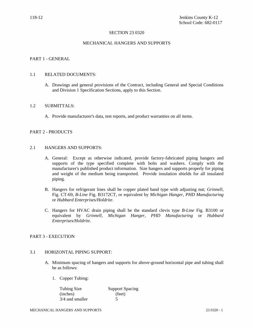
3.1 HORIZONTAL PIPING SUPPORT:
A. Minimum spacing of hangers and supports for above-ground horizontal pipe and tubing shall
be as follows:
1. Copper Tubing:
Tubing Size Support Spacing
(inches) (feet)
3/4 and smaller 5
118-12 Jenkins County K-12
School Code: 682-0117
MECHANICAL HANGERS AND SUPPORTS 23 0320 - 2
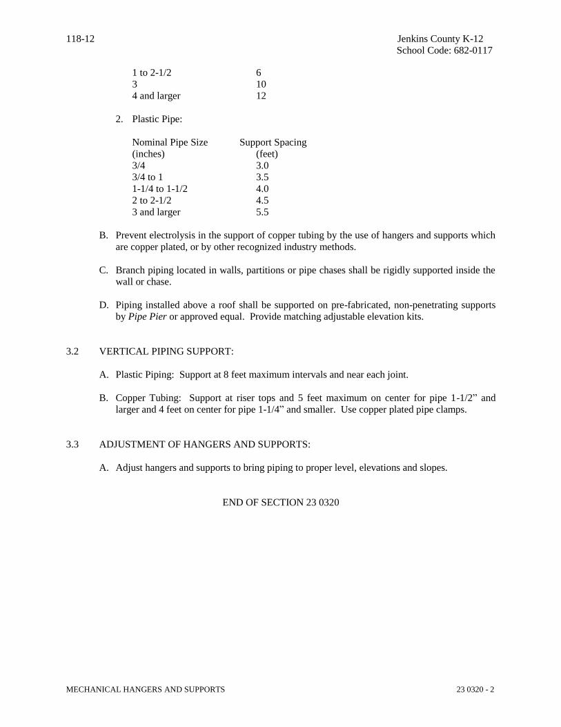
1 to 2-1/2 6
3 10
4 and larger 12
2. Plastic Pipe:
Nominal Pipe Size Support Spacing
(inches) (feet)
3/4 3.0
3/4 to 1 3.5
1-1/4 to 1-1/2 4.0
2 to 2-1/2 4.5
3 and larger 5.5
B. Prevent electrolysis in the support of copper tubing by the use of hangers and supports which
are copper plated, or by other recognized industry methods.
C. Branch piping located in walls, partitions or pipe chases shall be rigidly supported inside the
wall or chase.
D. Piping installed above a roof shall be supported on pre-fabricated, non-penetrating supports
by Pipe Pier or approved equal. Provide matching adjustable elevation kits.
3.2 VERTICAL PIPING SUPPORT:
A. Plastic Piping: Support at 8 feet maximum intervals and near each joint.
B. Copper Tubing: Support at riser tops and 5 feet maximum on center for pipe 1-1/2” and
larger and 4 feet on center for pipe 1-1/4” and smaller. Use copper plated pipe clamps.
3.3 ADJUSTMENT OF HANGERS AND SUPPORTS:
A. Adjust hangers and supports to bring piping to proper level, elevations and slopes.
END OF SECTION 23 0320
118-12 Jenkins County K-12
School Code: 682-0117
DUCTWORK AND ACCESSORIES 23 2110 - 1
SECTION 23 2110
DUCTWORK AND ACCESSORIES
PART 1 - GENERAL
1.1 RELATED DOCUMENTS:
A. Drawings and general provisions of the Contract, including General and Special Conditions
and Division 1 Specification Sections, apply to this Section.
1.2 QUALITY ASSURANCE:
A. Industry Standards:
1. Comply with SMACNA (Sheet Metal and Air Conditioning Contractor's National
Association) recommendations for fabrication, construction and details and installation
procedures, except as otherwise indicated.
2. Comply with ASHRAE (American Society of Heating, Refrigerating and Air
Conditioning Engineers) recommendations, except as otherwise indicated.
3. Provide composite ductwork insulation (insulation, coverings, sealers, mastics and
adhesives) with flame-spread rating of 25 or less and a smoke-developed rating of 50 or
less, as tested by ASTM E84 (NFPA 255) method.
4. Provide duct connectors which comply with applicable portion of UL 181 and bear label
of Underwriter's Laboratories.
1.3 SUBMITTALS:
A. Provide manufacturer's data, test reports, and product warranties as applicable for all items.
PART 2 - PRODUCTS
2.1 ABOVE GROUND DUCTWORK:
A. General: Galvanized steel ductwork shall be used for all supply, return, exhaust, and
ventilation ducts except as indicated otherwise by the contract documents. Black steel
ductwork shall be used for kitchen hood exhaust. Stainless steel duct shall be used for
dishwasher exhaust and fume hood exhaust. Preinsulated flexible duct shall be used to make
final concealed connections to diffusers, registers, and grilles. Length of flexible duct shall
not exceed five feet.
B. Galvanized Steel Ductwork: Ducts shall be fabricated from G90 galvanized sheet steel
complying with ASTM A527 and A525, lockforming quality. Concealed round ducts shall
be the spiral seam type or snap-lock type with matching fittings.
C. Black Steel Ductwork: Kitchen hood exhaust ducts shall be fabricated from 16 gauge black
118-12 Jenkins County K-12
School Code: 682-0117
DUCTWORK AND ACCESSORIES 23 2110 - 2
steel.
D. Stainless Steel Ductwork: Exposed ducts shall be fabricated from Type 316 stainless steel,
sheet form, with No. 4 finish.
E. Flexible Ducts: Flexible ducts shall be U.L. Listed as Class 1 Flexible Air Duct Material and
shall comply with NFPA Standards 90A and 90B. Duct shall be a factory fabricated
assembly composed of a polymeric liner duct bonded permanently to a coated spring steel
wire helix and supporting a fiberglass insulating blanket with a minimum R-value of 4.2.
Low permeability outer vapor barrier of fiberglass reinforced film laminate shall complete the
assembly. Duct shall be suitable for low and medium pressure systems and shall carry a full
5-year warranty. For all flexible duct connections to diffusers, registers and grilles, provide
rigid elbow brace accessory with one duct diameter centerline radius. Acceptable
manufacturers are Atco, Flexmaster, Genflex and Thermaflex.
2.3 DUCTWORK ACCESSORIES:
A. General: Except as otherwise indicated for each ductwork accessory, provide metal type,
gauge, weight, construction and reinforcing as required by size limitations, and applicable
SMACNA standards, including fittings, supports and appurtenances.
B. Flexible Connectors: Provide flexible connectors between supply and return duct
connections to equipment and as otherwise indicated on the drawings. Flexible connector
shall be constructed of neoprene permanently attached to 3 inch wide metal bands.
Connector shall be UL listed and shall be as manufactured by Durodyne, Ventfabrics or
Young Regulator.
C. Balancing Dampers: Provide single blade dampers for round ducts and rectangular ducts less
than 12” as indicated on the drawings. Dampers shall be constructed of galvanized steel.
Damper shall be installed complete with locking quadrants. For rectangular ducts 12” and
wider, provide opposed-blade type dampers constructed of galvanized steel mounted in a
galvanized steel channel frame. Blade spacing shall not exceed 6” and the top and bottom
edges of the blades shall be crimped to stiffen the blades. Damper blades shall be
interconnected by rods and linkages to provide simultaneous operation of all blades. Damper
shall be provided with an extended rod to permit installation of a damper regulator. Dampers
shall be as manufactured by Air Balance, Arrow, Dowco, Jer-Air, National Controlled Air,
Ruskin, Phillips-Aire, Safe-Air and United.
D. VAV Dampers: VAV dampers shall consist of a minimum 22 gauge galvanized steel damper
blade mounted in a minimum 18 gauge galvanized steel housing with crimped ends and a 24
VAC reversible electric actuator. Power supply shall be 120 VAC. A matching remote
adjustable space temperature sensor and integral entering air temperature sensor shall control
the damper position to maintain room setpoint. Provide all accessories for complete, stand-
alone operation. Dampers shall be by Carrier, Trane and York.
E. Round Take-Offs: Round take-offs shall be made using collars constructed of galvanized
steel equipped gasket flange and manual balancing damper with 2 inch handle standoff. Do
not furnish extractors or air scoops. Take-offs from low pressure rectangular trunk ducts
shall have 45 degree entry. Takeoffs shall be by Celcon, Crown, Flexmaster, Jer-Air,
Metalcraft, Sheet Metal Connectors, Thermaflex and United.
118-12 Jenkins County K-12
School Code: 682-0117
DUCTWORK AND ACCESSORIES 23 2110 - 3
F. Rectangular Take-Offs: Rectangular take-offs shall be made using collars constructed of
galvanized steel equipped with gasket flange and manual balancing damper with 2 inch
handle standoff. Do not furnish extractors or air scoops. All takeoffs shall have 45 degree
entry. Takeoffs shall be by Celcon, Crown, Flexmaster, Jer-Air, Metalcraft, Sheet Metal
Connectors, Thermaflex and United.
G. Fire Dampers (Walls and Floors): Provide curtain type, hinged blade, vertical and/or
horizontal mounting fire dampers, suitable for duct penetration or opening protection as
required on the drawings. Style ‘A’ dampers shall be used at wall register/grille locations.
Style ‘B’ dampers shall be used at duct penetrations. Dampers shall meet the requirements of
NFPA 90A and UL-555. Frame shall be minimum 20 gauge galvanized steel with 165
degree F fusible link. Blades shall be minimum 24 gauge galvanized steel. Dampers shall be
as manufactured by Air Balance, Greenheck, Nailor, National Controlled Air, Phillips-Aire,
Prefco, Ruskin, Safe-Air and United.
H. Smoke Dampers: Provide UL Classified Low Leakage smoke dampers suitable for duct
penetration or opening protection as required on the drawings. Dampers shall meet the
requirement of NFPA 90A and UL-555S. Frame shall be minimum 16 gauge galvanized
steel. Blades shall be minimum 14 gauge galvanized steel airfoil design with silicon rubber
edge seals, Leakage Class 1. The assembly shall include a 120 VAC 2-position actuator,
power-to-open, spring-to-close. Interlock with the building fire alarm system to close on an
alarm condition. Smoke detectors will be furnished and installed by Division 26. Dampers
shall be as manufactured by Air Balance, Greenheck, Nailor, National Controlled Air,
Phillips-Aire, Prefco, Ruskin, Safe-Air and United.
I. Access Doors: Duct access doors shall be provided at all fire dampers, smoke dampers,
combination fire/smoke dampers, and at control items mounted within ducts. Access doors
shall be the double-wall insulated type constructed of galvanized steel not less than 24 gauge
for the door and 22 gauge for the frame. Insulation shall be 1 inch thick and shall be rigid
and self-sealing. Doors shall have cam locks on at least two sides. Frame shall have
knockover edges for attachment to duct by preening and a vinyl gasket shall be provided
between duct and frame. Doors shall be as large as possible and as close as possible to the
item served. Door shall be by Air Balance, Greenheck, Nailor, National Controlled Air,
Phillips-Aire, Prefco, Ruskin, Safe-Air and United.
2.4 DUCTWORK INSULATION:
A. General: Refer to the mechanical plans for duct insulation types and locations. Insulation
shall be as manufactured by Certainteed, Knauf, Manville and Owens Corning.
B. Duct Wrap: Type “A” Duct wrap shall be 2” thick, 0.75 pcf density, blanket type fiberglass
insulation with vapor barrier and minimum R-Value of 6.7.
C. Duct Liner: Type “A” Duct liner shall be 1” thick, 1.5 pcf density, flexible black fiberglass
with minimum R-Value of 3.6.
D. Duct Board: Exterior board type insulation shall be 2” thick, 3 pcf density with minimum R-
Value of 8.0. Insulating board shall be faced with foil reinforced Kraft (FRK) vapor barrier.
E. Kitchen Hood Exhaust Duct Insulation: All kitchen hood exhaust ductwork shall be
insulated with two layers of flexible fire-rated duct wrap suitable for zero clearance to
118-12 Jenkins County K-12
School Code: 682-0117
DUCTWORK AND ACCESSORIES 23 2110 - 4
combustibles.
F. Ductwork Insulation Accessories: Provide mechanical fasteners as recommended by the
insulation manufacturer.
G. Ductwork Insulation Compounds: Provide cement, adhesives, coatings, sealers, protective
finishes, and similar compounds as recommended by the insulation manufacturer for the
applications indicated.
2.5 MISCELLANEOUS MATERIALS:
A. General: Provide miscellaneous materials and products of the types and sizes indicated and
where not otherwise indicated, provide type and size required to comply with ductwork
system requirements including proper connection of ductwork and equipment.
B. Duct Sealant: Duct Sealant for above ground ductwork shall be a mastic suitable for the
pressure classification in accordance with SMACNA HVAC Duct Construction Standard".
All joints and seams shall be sealed.
C. Ductwork Support Materials: Provide hot-dipped galvanized steel rods, fasteners, anchors,
straps, angles and trim for support of ductwork. Wires shall not be acceptable. Ductwork
installed above a roof shall be supported on pre-fabricated, non-penetrating supports by Pipe
Pier or approved equal. Provide matching adjustable elevation kits.
D. Weatherproof Coating: Ductwork exposed outside shall be completely coated with
weatherproof mastic coating suitable for metal ductwork and thermal insulation. The coating
shall have a white color with service temperature range of -20° to 180°F, nonflammable when
wet, maximum flame spread rating of 15, smoke developed rating of zero. Alternatively,
insulate exterior ductwork with “Techna-Duc” pre-manufactured, interlocking, insulated
panel system by PTM Manufacturing or equal.
2.6 DUCT FABRICATION:
A. Shop fabricate ductwork in 4, 8, 10, or 12 foot lengths, unless otherwise indicated or required
to complete runs. Pre-assemble in the shop to the greatest extent possible, so as to minimize
field assembly of systems. Disassemble systems only to the extent necessary for shipping
and handling. Match-mark sections for re-assembly and coordinated installation.
B. Fabricate ductwork with joints, seams and reinforcements as required in the latest edition of
SMACNA HVAC Duct Construction Standards, 2” static pressure rating.
C. Fabricate duct fittings to match adjoining ducts and to comply with duct requirements as
applicable to fittings. Elbows shall be either the curved radius type or the square type with
turning vanes. Curved radius elbows shall have a centerline radius equal to 1.5 times the duct
width. Curved radius elbows with square throats shall not be acceptable.
D. Fabricate ductwork with accessories installed during fabrication to the greatest extent
possible. Where ducts are specified to lined, make allowances for the thickness of the liner.
Duct sizes shown on the drawings are clear, inside dimensions.

118-12 Jenkins County K-12
School Code: 682-0117
DUCTWORK AND ACCESSORIES 23 2110 - 5
E. Kitchen hood exhaust ductwork and dishwasher exhaust ductwork and joints and seams shall
have liquid-tight continuous external weld per NFPA-96.
PART 3 - EXECUTION
3.1 INSTALLATION OF DUCTWORK:
A. General: Assemble and install ductwork in accordance with the latest edition of SMACNA
HVAC Duct Construction Standards and with recognized industry practices which will
achieve air tight noiseless systems, capable of performing each indicated service. Install each
run with a minimum of joints. Align ductwork accurately at connections, and with internal
and external surface smooth. Support ducts rigidly with suitable ties, braces, hangers and
anchors of the type which will hold ducts true-to-shape and prevent buckling. Hanger
locations shall be coordinated with the building structure and finish conditions.
B. Complete fabrication of work at the project as necessary to match shop fabricated work and
accommodate installation requirements.
C. Locate ductwork runs, except as otherwise indicated, vertically and horizontally and avoid
diagonal runs wherever possible. Locate runs as indicated by plans, diagrams, details and
notations or, if not otherwise indicated, run ductwork in the shortest route which does not
obstruct usable space or block access for servicing the building and its equipment.
Coordinate the layout with piping, lighting layouts and similar finished work and plumbing
risers. Duct layouts shown are diagrammatic and actual location of duct shall be field
verified and coordinated by the duct fabricator prior to beginning fabrication of duct systems.
D. Duct collars shall be provided where ducts pass through walls and partitions which extend
full height to the underside of the roof structure. Collars shall be fabricated from 22 gauge
galvanized steel sheet. Duct collars shall be provided on both sides of walls and partitions,
except collar shall be omitted on that side of the wall where registers and grilles are installed.
Flanges shall be installed tight against the wall. The space between the duct and the wall
shall be packed with mineral wool.
E. Coordinate duct installations with installation of accessories, dampers, equipment, controls
and other associated work of the ductwork system.
F. Route kitchen hood and dishwasher exhaust ductwork as directly as possible. Horizontal
ductwork must slope minimum ¼” per foot to drain toward the hoods. Do not create dips and
traps which can collect residue. Branch ducts bottoms must connect flush to main duct
bottoms. Provide NFPA-96 removable duct access doors every twelve feet and at changes in
direction. Access doors shall be sized to permit duct cleaning. Conform to NFPA-96 for
locations and installation details. At each exhaust fan, install an approved flexible duct
connection.
3.2 INSTALLATION OF INSULATION:
A. Duct Wrap: Wrap shall be wrapped around duct work with all circumferential joints butted
and longitudinal joints overlapped a minimum of 2”. Adhere insulation to duct with 4” strips
of fire resistant adhesive at 8” on centers. On circumferential joints, the 2” flange on the
118-12 Jenkins County K-12
School Code: 682-0117
DUCTWORK AND ACCESSORIES 23 2110 - 6
facing shall be taped with minimum of 3” wide foil reinforced Kraft tape. On longitudinal
joints the overlap shall be taped with a minimum 3” wide foil reinforced Kraft tape. On ends
of insulation use 3” wide foil reinforced Kraft tape to fasten insulation ends to duct. For duct
widths 24” and greater, provide additional mechanical fasteners on 18” centers on the bottom
of the duct to prevent sagging. Insulate that part of the supply diffusers above the ceiling so
that there is no uncovered metal surface subject to condensation. Provide taped-on 12”x12”
squares of insulation over damper regulators located above ceilings.
B. Duct Liner: Liner shall be applied to the flat sheet with 100% coverage of fire resistant
adhesive. The duct liner shall be cut to assure snug corner closing joints. The black surface
of the liner shall face the air stream. On horizontal runs, tops of ducts over 12” in width and
sides over 16” in height shall be additionally secured with welded pins and speed clips or
gripnails spaced on a maximum of 16” pin centers. On vertical runs, welded pins and speed
clips or gripnails shall be spaced on maximum 16 inch pin centers on all widths over 12”.
Pins shall start within 2” of the leading edge of each section. Pins shall be cut close to the
speed clip. Clips shall be drawn flush only and not so as to compress the liner. Coat all
exposed edges and the leading edge of all cross joints with fire resistant sealant.
C. Duct Board: Board shall be applied using mechanical fasteners such as weld pins or stick
clips on 12” centers and not less than 3” from each edge or corner of the board. Apply
additional pins or clips where required to hold the insulation tightly against the duct surface.
Apply round vapor seal FRK pressure-sensitive patches to each fastener. Apply 5” wide
pressure-sensitive joint sealing tape to match jacket at all insulation edges and butt joints.
3.3 CLEANING AND PROTECTION:
A. Clean ductwork internally, unit-by-unit as it is installed, of dust and debris. Clean external
surfaces of foreign substances which might cause corrosive deterioration of the metal or,
where ductwork is to be painted, might interfere with painting or cause paint deterioration.
B. Temporary Closure: At ends of ducts which are not connected to equipment or air
distribution devices at the time of ductwork installation, provide temporary closure of
polyethylene film or other covering which will prevent the entrance of dust and debris.
END OF SECTION 23 2110
118-12 Jenkins County K-12
School Code: 682-0117
AIR DISTRIBUTION 23 2210 - 1
SECTION 23 2210
AIR DISTRIBUTION
PART 1 - GENERAL
1.1 RELATED DOCUMENTS:
A. Drawings and general provisions of the Contract, including General and Special Conditions
and Division 1 Specification Sections, apply to this Section.
1.2 QUALITY ASSURANCE:
A. Titus is the Basis of Design manufacturer for grilles, registers and diffusers. Equivalent
equipment by Carnes, Krueger, Metalaire, Nailor and Price that meets performance,
capacity, space and other requirements of the design documents shall be acceptable.
B. Greenheck is the Basis of Design manufacturer for louvers. Equivalent equipment by Arrow,
Penn, Louvers And Dampers, Ruskin and United Enertech that meets performance, capacity,
space and other requirements of the design documents shall be acceptable.
C. Industry Standards: Comply with National Fire Protection Association Standard No. 90A, as
applicable to construction and installation of required devices.
1.3 SUBMITTALS:
A. Provide manufacturer's data, test reports, and product warranties for all items as applicable.
PART 2 - PRODUCTS
2.1 GRILLES, REGISTERS, AND DIFFUSERS:
A. Ceiling Diffusers: T-bar lay-in style diffusers shall be the full 2x2 face type with round neck,
three or four cones, and one-way, two-way, three-way, or four-way throw as indicated.
Diffusers shall be of stamped aluminum construction with white finish. Do not furnish
dampers.
B. Perforated Face Diffusers: Diffusers shall be the square type with removable face. Diffusers
shall have fully adjustable, 3-way or 4-way pattern control element and opposed blade
damper. Face finish shall be white and interior shall be flat black. The face shall fit into a
2'x2' T-bar ceiling grid.
C. Ceiling Return/Exhaust Grilles: Eggcrate grilles shall be all aluminum construction with ½”
square eggcrate louvers, 1” deep, with white finish. All 1'x2', 2'x2', and 2'x4' grilles in lay-in
ceilings shall be the lay-in type. All other sizes shall have a flanged frame.

118-12 Jenkins County K-12
School Code: 682-0117
AIR DISTRIBUTION 23 2210 - 2
D. Wall Return/Exhaust Grilles: Horizontal fixed-blade grilles shall be of extruded aluminum
construction with 45 degrees blades on 3/4 inch centers and white finish.
E. Heavy Duty Return/Exhaust Grilles: Heavy duty grilles shall have minimum 18 gauge steel
frames and 1/8 inch face bars at 40 degree deflection with white finish.
F. Filter Grilles: Shall be the same as return air registers and grilles with the addition of a
hinged face and rack for 1 inch thick filters.
2.2 LOUVERS:
A. Stationary Louvers: Louvers shall be the drainable-blade type of minimum 0.081" thick
extruded aluminum construction, 6" deep, with a full jamb section and channel frame. Blades
shall be set at 40 on 5 inch centers. Provide a removable aluminum insect screen on the
inside face of the louver. Finish shall be a factory applied primer suitable for field painting.
PART 3 - EXECUTION
3.1 INSTALLATION:
A. General: Install devices as detailed on the drawings and in accordance with manufacturer's
written instructions and in accordance with recognized industry practices.
B. Coordinate with other work, including ductwork and ductwork accessories and ceiling system
as necessary to interface installation of grilles and diffusers properly with other work.
C. Ceiling mounted devices to be installed in lay-in tile ceilings shall be compatible with
24"x24" or 24"x48" T-bar grid as applicable. Refer to Architectural Reflected Ceiling Plans
for exact locations of grilles, registers and diffusers. For flush mounted devices in T-bar
ceilings, special care shall be taken to install devices in the center of ceiling tiles. Sagging
will not be permitted. Provide rear sheet metal angle bracing.
END OF SECTION 23 2210
118-12 Jenkins County K-12
School Code: 682-0117
FANS 23 2310 - 1
SECTION 23 2310
FANS
PART 1 - GENERAL
1.1 RELATED DOCUMENTS:
A. Drawings and general provisions of the Contract, including General and Special Conditions
and Division 1 Specification Sections, apply to this Section.
1.2 QUALITY ASSURANCE:
A. Greenheck is the Basis of Design manufacturer. Equivalent equipment manufactured by
Acme, Carnes, Cook, Penn, Stanley and Twin City that meets performance, capacity, space
and other requirements of the design documents shall be acceptable.
B. Industry Standards:
1. Provide fans which bear Air Movement and Control Association (AMCA) certified
performance rating seals.
2. Provide fan components which have been listed and labeled by Underwriters'
Laboratories.
3. Comply with applicable portion of National Electrical Manufacturer's Association
standards for motors.
1.3 SUBMITTALS:
A. Provide manufacturer's data, test reports, and product warranties on all items.
PART 2 - PRODUCTS
2.1 WALL MOUNTED PROPELLER EXHAUST FANS:
A. Provide wall mounted propeller type fans of the size and type as shown on the drawings. Fan
shall be direct driven or belt driven as indicated with continuous duty motors resiliently
mounted in a basket and guard meeting OSHA requirements. Propeller blades shall be
statically and dynamically balanced. Fan panels shall have a deep spun steel venturi and
welded corners. Provide ECM motor. Provide disconnect switch, motor side fan guard,
gravity wall shutter and mounting sleeve. Install fan behind stationary louver. Provide speed
controllers for direct drive fans.
2.2 ROOF MOUNTED CENTRIFUGAL EXHAUST FANS:

118-12 Jenkins County K-12
School Code: 682-0117
FANS 23 2310 - 2
A. Provide roof mounted centrifugal fans of the size and type as scheduled on the drawings.
Fans shall be constructed with watertight housing capable of resisting specified wind loads
per Section 239110 and shall be direct or belt-driven as indicated. Motor shall be in a
compartment out of the air stream. Housings shall be minimum 16 gauge spun aluminum.
Fan wheel shall be of aluminum, dynamically and statically balanced, non-overloading
backward-curved blades mounted on steel shaft. Equip with self-aligning heavy-duty
bearings designed for end thrust and lubricated for a minimum of 10 years usage at operating
temperatures of -65 to 100 degrees F. Provide vibrationless lubricated ball bearing motor
with integral thermal overload protection and electrical disconnect switch under ventilator
cap. Provide ECM motor. Provide aluminum bird screen, backdraft dampers, and matching
roof curb.
2.3 IN-LINE CENTRIFUGAL FANS:
A. Provide an in-line centrifugal fan of the size and type as scheduled on the drawings. Fan
housing shall be heavy-gauge painted steel. Fans shall be direct or belt-driven as indicated
with aluminum centrifugal wheels with backwardly inclined, non-overloading blades. Inlets
shall be deep spun for nonturbulent entrance. Provide a 100% gasketed panel to permit
access to interior, and provide an internal terminal box mounted on the exterior. Provide
ECM motor. Provide disconnect switch, backdraft damper and hanger brackets with
vibration isolators.
2.4 FLY FANS:
A. Provide wall mounted fly fans over the interior of doors as shown on the drawings. Capacity
shall be as scheduled on the drawings. Cabinet shall be manufactured of one-piece molded
high density polycarbonate. Fan motor shall be continuous duty type with permanently
lubricated sealed ball bearings, totally enclosed, resilient mounting and thermal overload
protection. Provide adjustable intake louvers and adjustable air directional control vanes at
outlet nozzle. Provide beige finish and micro switch for automatic on/off control.
2.5 FUME HOOD EXHAUST FANS:
A. Provide a high-plume laboratory exhaust system of the size and type as scheduled on the
drawings. Fan housing shall be welded steel with a minimum of 4 mils of Hi-Pro Polyester
Resin. No uncoated metal fan parts shall be acceptable. A high velocity conical discharge
nozzle shall be supplied by the fan manufacturer and be designed to provide at least 3000
FPM. Discharge stack caps or hinged covers, impeding exhaust flow shall not be permitted.
Provide housing drain for removal of rain and condensation. A bolted and gasketed access
door shall be supplied in the fan housing allowing for impeller inspection or removal of
impeller, shaft and bearings without removal of the fan housing. Fan shall be mounted on
factory curb / equipment support and the installed assembly shall be rated for specified wind
loads per Section 239110 with no additional supports (guy wires). Fan impeller shall be
centrifugal, backward inclined, with non-stall characteristics. The impeller and assembly shall
be electronically balanced both statically and dynamically per AMCA. Fan impeller shall be
manufactured of aluminum (AMCA class B spark resistant), fully welded and coated with a
minimum of 4 mils of Hi-Pro Polyester resin. Belts shall be sized for a minimum of 150% of
the motor horsepower and drives shall be supplied with a minimum of two operating belts.

118-12 Jenkins County K-12
School Code: 682-0117
FANS 23 2310 - 3
Fan shaft bearings shall be ball or roller pillow block type and be sized for an L-10 life of no
less than 100,000 hours. Bearings shall be fixed to the fan shaft using concentric mounting
locking collars, which reduce vibration, increase service life, and improve serviceability.
Bearings that use set screws shall not be allowed. Bearings shall have extended lube lines.
Provide ECM motor. Provide fan with external disconnect switch in weathertight enclosure.
2.6 RESIDENTIAL RANGE HOODS:
A. Residential range hoods shall be the steel shell type with mitered sides and hemmed bottom
suitable for mounting under a wall cabinet. Hoods shall be 30 inches wide and shall have a
75 watt light with safety lens, light switch, 190 cfm 2-speed fan with rocker switch, washable
aluminum filter, polymeric fan blades, backdraft damper, 7” round duct connection. Hoods
shall have a finish selected by the Architect.
B. Each hood shall have a pre-engineered, pre-assembled, wet chemical automatic fire
extinguisher unit consisting of an extinguisher kit, a piping kit, and a detection kit. All
components shall be installed in the hood and wall cabinet. The extinguisher kit shall have a
pressurized storage cylinder with chemical agent, pressure gauge, valve assembly, micro
switch, cable adjuster, spring, and mounting bracket. The piping kit shall consist of rigid
piping and flexible hose with two system appliance nozzles equipped with adjustable swivels
and full cone spray pattern. The detection kit shall consist of cable, corner pulleys, and four
reusable link detectors. Provide an alarm horn and necessary shutoff devices to automatically
shut off all power to the range. Provide a contact for connection to the building Fire Alarm System.
Installation shall be in accordance with the manufacturer’s instructions.
PART 3 - EXECUTION
3.1 INSTALLATION OF FANS:
A. General: Except as otherwise shown or specified, install fans in accordance with
manufacturer's written instructions and in accordance with National Electrical Code (NEC)
and recognized industry practices.
B. See section 238110 for fan controls.
3.2 TESTING:
A. After installation of fans has been completed, test each unit to demonstrate proper operation
at performance requirements specified, including, but not limited to, proper rotation of
impeller. When possible, field correct malfunctioning units, then retest to demonstrate
compliance. Replace units which cannot be satisfactorily corrected.
END OF SECTION 23 2310

118-12 Jenkins County K-12
School Code: 682-0117
KITCHEN HOOD VENTILATION SYSTEM 23 2510 - 1
SECTION 23 2510
KITCHEN HOOD VENTILATION SYSTEM
PART 1 - GENERAL
1.1 RELATED DOCUMENTS:
A. Drawings and general provisions of the Contract, including General and Special Conditions
and Division 1 Specification Sections, apply to this Section.
B. Refer to Food Service bid documents for related mechanical contractor work.
1.2 QUALITY ASSURANCE:
A. Captive-Air is the Basis of Design manufacturer. Equivalent equipment manufactured by
Accurex and Greenheck shall be acceptable.
B. Industry Standards:
1. Hoods shall be ETL Listed and NSF Listed.
2. Provide components and assemblies which have been labeled by Underwriter's
Laboratories (UL).
3. Comply with the requirements of the National Fire Protection Association (NFPA) for
fabrication and installation. Specifically comply with NFPA 96, Standard for Ventilation
Control and Fire Protection of Commercial Cooking Operation and with NFPA 17A,
Wet Chemical Extinguishing System.
1.3 SUBMITTALS:
A. General: Provide manufacturer's data, certificates, test reports, and product warranties as
applicable for all items.
B. Shop Drawings: Submit dimensioned fabrication drawings for equipment including plans,
elevations, and sections, at minimum scale of 3/4" = 1' -0", showing materials and gauges
used. Submit dimensioned shop drawings for installation of hood fire protection system.
Submit wiring diagrams.
PART 2 - PRODUCTS
2.1 KITCHEN HOODS:
A. Type I Grease Filter Exhaust Hoods: The hood shall be, where exposed, stainless steel type
304 with #4 finish. All joints and seams shall have full liquid tight external welds. Visible
welds shall be ground smooth, and if stainless steel, be polished to a #4 finish. The hood
shall be the box type with vertical sides. The hood shall have integral exhaust duct collar(s).
118-12 Jenkins County K-12
School Code: 682-0117
KITCHEN HOOD VENTILATION SYSTEM 23 2510 - 2
Each hood shall have a filter housing of the same material as the hood complete with ETL
Listed stainless steel 2 inch thick panel type grease filters the full length. Filters shall be a
single-stage baffle design with minimum 90% grease extraction efficiency at 7 microns. The
filter housing shall be equipped with a pitched drip tray the full length of the hood with
grease cups for easy removal and daily cleaning. Hoods with ceiling makeup air plenum
shall have double wall insulated front.
2.2 HOOD ACCESSORIES:
A. Electrical: U.L. listed, four foot, two-lamp, recessed fluorescent light fixtures for grease use
shall be installed on six or seven foot centers and completely wired to a J-box on the top of
the hood. Provide an integral Kitchen Hood Demand Control Ventilation System to
automatically reduce exhaust and supply airflows based on demand. Fan speed shall be based
on sensing exhaust duct temperature. Provide variable speed drives for each fan. Provide an
integral heat sensor and associated controls to automatically turn on and off fan(s) based on
demand. Provide a 6”x6” wall mounted recessed control panel with light switch and fan
switch. EF and MAH shall be controlled by the fan switch. This control panel shall be
mounted 48” AFF. Additional control devices shall be mounted in another recessed control
panel located near the ceiling. All conduit shall be run in a concealed manner.
B. Duct Collars: The U.L. Labeled exhaust duct collars must be installed at the factory and it is
the responsibility of the contractor to verify the location of the duct collars to avoid
interference with the structure or other obstructions. The exhaust ducts and supply ducts shall
fit inside the duct collars of the hood and be seated, but not welded, into the holding clips
provided.
C. Makeup Air Plenum: Provide a matching ceiling mounted stainless steel makeup air plenum
with full length, full perimeter perforated face discharge panels, internal insulation and
supply air duct collars for up to 90% makeup air. Discharge velocity shall be in the range of
140-160 fpm. Provide an adjacent air conditioning plenum for conditioned air alongside the
makeup air plenum. See plans for details. The overall width of the plenum shall be
minimum 18 inches all around. Provide a 12”x12” open area on each end of the plenum for
installation of a utility chase by other trades. The chase areas shall be covered with a
removable stainless steel panel.
D. Panels: Furnish a stainless steel fascia panel around entire hood to extend the hood surface 6
inches above the finished ceiling. Panel finish shall match the hood finish.
E. Fire Protection System:
1. Furnish a wet chemical system providing complete fire protection of duct, hood, and
cooking equipment surfaces. Installation shall be in compliance with chemical
manufacturer's U.L. Listing. All piping shall be run in a concealed manner. Piping
extending up through chase to duct and hood nozzles shall be fitted with sleeves forming
grease tight joints. Exposed piping of surface protection nozzles shall have stainless steel
sleeves with chrome plated elbows.
2. System shall be activated by fusible links connected to an automan release. Fit automan
release with an electric double-pole, double-throw microswitch for control circuit.
Makeup Air Heater supply fan shall be shut down when fire protection system is
activated, leaving the exhaust fan running.
3. Provide a U.L. listed mechanical gas valve, to provide automatic gas fuel shutoff for all

118-12 Jenkins County K-12
School Code: 682-0117
KITCHEN HOOD VENTILATION SYSTEM 23 2510 - 3
gas operated appliances protected by the system. The valve shall incorporate a manual
reset.
4. Provide auxiliary factory installed relays to automatically trip shunt trip safety devices for
electrically operated appliances protected by the system. The devices shall be as
indicated on the electrical drawings. Also provide a relay to automatically signal the
building fire alarm system.
5. The chemical cylinders and controls shall be located in fire control cabinet wall mounted
in the Kitchen near the ceiling. Provide a remote manual pull station and interlock with
system.
2.3 EXHAUST FANS:
A. The exhaust fan shall be U.L. listed for grease duct use and shall be the upblast type of spun
aluminum construction with belt-driven fan with backward-inclined or airfoil blades only,
containing a built-in grease trough and having a completely isolated motor compartment and
hinged frame. Provide ECM motor. No birdscreens or backdraft dampers will be permitted
per NFPA 96. Furnish an 18 gauge galvanized curb, minimum 18 inches high, to raise fan
discharge 40 inches minimum above the roof surface.
B. Provide a variable frequency drive to vary the speed of the fan in response to the Kitchen
Hood Demand Control Ventilation System furnished with the kitchen hood. Fan motor shall
be suitable for inverter duty. Provide external disconnect switch in weathertight enclosure,
dual drive grooves, one set of spare belts, stainless steel fasteners, stainless steel shaft, wiring
pigtail and non-stick wheel coating.
2.4 MAKEUP AIR HEATERS:
A. Makeup Air Heater shall be the outdoor type with direct-fired gas heat and shall be ETL
listed. Unit shall be horizontal downblast type as shown on drawings. Unit shall be of
internal frame type construction with G90 galvanized steel frames and panels. Metal-to-
metal surfaces exposed to weather shall be sealed. All components shall be accessible
through removable or hinged doors. Unit casing shall be insulated with 1 inch fiberglass liner
in accordance with NFPA 90A and tested to meet UL 181 erosion requirements. Secure
insulation with waterproof adhesive and permanent mechanical fasteners.
B. Provide filter rack with pleated minimum MERV 7 filters. Do not exceed 550 PFM face
velocity. Provide weather hood with birdscreen mounted at the intake. Provide automatic
two-position damper. Provide downturn plenum with duct flanges.
C. Centrifugal fans shall be double width, double inlet. Fan and motor shall be mounted on a
common base with vibration isolators. Fan wheels shall be statically and dynamically
balanced. Ground and polished steel fan shafts shall be mounted in permanently lubricated
ball bearings or ball bearing pillow blocks. Bearings shall be selected for minimum L10 life
in excess of 100,000 hours at maximum cataloged speeds. Motors shall comply with EPAct
standards for ODP and TE enclosures. Motors shall be permanently lubricated, heavy-duty
type, matched to the fan load. Drives shall be sized for a minimum of 150% driven HP. 10
HP and less shall have an adjustable drive pulley. Provide built-in variable frequency drive
and inverter duty fan motor for VAV operation.
D. All internal electrical components shall be prewired for single point power connection.

118-12 Jenkins County K-12
School Code: 682-0117
KITCHEN HOOD VENTILATION SYSTEM 23 2510 - 4
Control center shall include a motor starter, control circuit fusing, control transformer for 120
VAC circuit, integral door interlocking disconnect switch and terminal strip. Provide
adjustable overload protection and single phase protection.
E. Roof curbs shall be furnished under Section 23 9110.
F. Direct-fired natural gas system shall have a draw-through design and field adjustable burner
baffles. Gas trains up to 400,000 Btu/hr shall include a direct spark ignition system. Gas
trains greater than 400,000 Btu/hr shall include a pilot ignition system with digital coded fault
indicator. Dual safety valves shall be industrial duty and use 120VAC control signals.
Temperature control shall incorporate an electronic modulation control system. On a call for
heat from a unit mounted ductstat, controls shall modulate the burner between 50% and
100%, as required. All controls and sensors required for a complete, operable system shall be
furnished and installed under this section.
PART 3 - EXECUTION
3.1 INSTALLATION:
A. Installer shall examine roughed-in mechanical and electrical services, and installation of
floors, walls, columns, ceilings, and other conditions under which food service equipment
work is to be installed; verify dimensions of services and substrates before fabricating work.
Notify Contractor of unsatisfactory conditions for proper installation of equipment. Do not
proceed with fabrication and installation until unsatisfactory dimensions and conditions have
been corrected in a manner satisfactory to the installer. Control wiring and devices for
complete, operable systems shall be provided and installed under the Mechanical
specifications. Wiring shall be installed in conduit provided and installed under the Electrical
specifications.
B. Exhaust Fan and Makeup Air Heater shall be furnished and installed as a packaged assembly.
3.2 TESTING:
A. Test each item of operational equipment to demonstrate that it is operating properly, and that
controls and safety devices are functioning. Repair or replace equipment which is found to
be defective in its operation including units which are below capacity or operating with
excessive noise or vibration. At the time of installation, an authorized dealer of the chemical
system shall complete and certify the system.
END OF SECTION 23 2510

118-12 Jenkins County K-12
School Code: 682-0117
DUST COLLECTION SYSTEM 23 2710 - 1
SECTION 23 2710 - DUST COLLECTION SYSTEM
PART 1 - GENERAL
1.01 RELATED DOCUMENTS:
A. Drawings and general provisions of the contract, including General and Special Conditions
and Division 1 Specification Sections, apply to this section.
1.02 QUALITY ASSURANCE:
A. The existing dust collector and return air bag filter assembly shall be relocated as shown on
the plans.
B. Industry Standards:
1. System installation shall conform to NFPA 664 - Prevention of Fires and Explosions in
Wood Processing and Woodworking Facilities.
2. System installation shall conform to NFPA 650 - Pneumatic Conveying Systems for
Handling Combustible Particulate Solids.
3. System installation shall conform to NFPA 91 - Exhaust Systems for Air Conveying of
Materials.
1.03 SUBMITTALS:
A. Provide manufacturer's data, test reports, and product warranties.
PART 2 - PRODUCTS
2.01 DUST COLLECTION SYSTEM:
A. Dust collection exhaust ductwork shall be spiral seam galvanized steel, minimum 18 gauge,
class 2 industrial grade per NFPA 91, SMACNA and Industrial Ventilation with welded
joints, matching fittings and paint-grip finish.
B. Provide necessary collars, hoods, etc. as required to connect to the woodworking equipment.
Provide a lockable blast gate in each branch duct. Locate midway between the trunk duct and
equipment connection.
C. Each branch duct shall connect to the trunk at a 45 degree angle. Use long sweep elbows.
D. Locate the existing return air bag filter assembly indoors and connect to dust collector with
full size duct.
118-12 Jenkins County K-12
School Code: 682-0117
DUST COLLECTION SYSTEM 23 2710 - 2
PART 3 - EXECUTION
3.01 INSPECTION:
A. Installer must examine areas and conditions under which dust collection system is to be
installed and notify Contractor in writing of conditions detrimental to proper completion of
work. Do not proceed with work until unsatisfactory conditions have been corrected in a
manner acceptable to Installer.
3.02 INSTALLATION:
A. General: Connect ductwork to mechanical equipment in manner shown, and comply with
equipment manufacturer's instruction where not otherwise indicated.
3.03 TESTING:
A. Upon completion of installation of equipment and system, start-up and operate system to
demonstrate compliance with design requirements.
END OF SECTION 23 2710

118-12 Jenkins County K-12
School Code: 682-0117
WELDING EXHAUST SYSTEM 232720 - 1
SECTION 232720 - WELDING EXHAUST SYSTEM
PART 1 - GENERAL
1.1 RELATED DOCUMENTS:
A. Drawings and general provisions of the Contract, including General and Special Conditions
and Division 1 Specification Sections, apply to this Section.
1.2 QUALITY ASSURANCE:
A. Car-mon is the Basis of Design manufacturer. Equivalent equipment manufactured by
ACME, Engwald, and Lincoln Environmental Systems shall be acceptable.
B. Industry Standards:
1. System installation shall conform to NFPA 91 - Exhaust Systems for Air Conveying of
Materials.
1.3 SUBMITTALS:
A. Provide manufacturer's data, test reports, and product warranties.
PART 2 - PRODUCTS
2.1 WELDING EXHAUST SYSTEM:
A. Exhaust ductwork shall be spiral seam galvanized steel, minimum 18 gauge, Class 1
Industrial Grade per NFPA 91, SMACNA and Industrial Ventilation with welded joints,
matching fittings and paint-grip finish. Use long sweep elbows. Duct joints and seams shall
be sealed with heat shrink sleeves.
B. Hoses shall be flexible polyester fabric that is flame retardant, oil resistant and spatter
resistant with extra durable wearstrip. Provide one 12 foot long hose per booth, sized per
drawings. Provide adaptors as needed.
C. Suction heads shall be Model M welding fume receptor formed of high impact rated non-
conductive ABS thermoset polymer compound. Fume receptor to be provided with integral
swivel collar, omni-directional mount, circular magnetic base, convenience handle and
collector screen of corrosion resistant metal. Provide Model MD hand damper with locking
quadrant and is built into the swivel collar of welding fume receptor. Provide adaptors as
needed.
D. Accessories: Provide clean-out kit for end of fume hood exhaust run.
A. Welding Exhaust Fans: Fans shall be utility set type with side intake and up discharge as
Master
WELDING EXHAUST SYSTEM 232720-2
shown on drawings. Fan housing to be aerodynamically designed with high-efficient inlet,
engineered to reduce incoming turbulence. Housing shall be continuously welded heavy
gauge steel and all interior and exterior surface steel shall be coated with a minimum of 2-
4mils of polyester urethane. Housing and bearing support shall be constructed of welded
structural steel members to prevent vibration and rigidly support the shaft and bearings. Belt
guard and shaft guard shall be included to completely cover the motor pulley and belt. Fan
wheel shall be radial type. Fan is to have AMCA Class B spark rating. Fan shall be roof
mounted on an equipment base per section 239110. Fan to be provided with unit mounted
disconnect.
PART 3 - EXECUTION
3.1 INSPECTION:
A. Installer must examine areas and conditions under which welding exhaust system is to be
installed and notify Contractor in writing of conditions detrimental to proper completion of
work. Do not proceed with work until unsatisfactory conditions have been corrected in a
manner acceptable to Installer.
3.2 INSTALLATION:
A. General: Connect ductwork to mechanical equipment in manner shown, and comply with
equipment manufacturer's instruction where not otherwise indicated.
3.3 TESTING:
A. Upon completion of installation of equipment and system, a factory representative shall start-
up and operate the system to demonstrate compliance with design requirements.
END OF SECTION 232720
118-12 Jenkins County K-12
School Code: 682-0117
ELECTRIC HEATERS 23 3110 - 1
SECTION 23 3110
ELECTRIC HEATERS
PART 1 - GENERAL
1.1 RELATED DOCUMENTS:
A. Drawings and general provisions of the Contract, including General and Special Conditions
and Division 1 Specification Sections, apply to this Section.
1.2 QUALITY ASSURANCE:
A. QMark is the Basis of Design manufacturer. Equivalent equipment by Berko, Chromalox,
Markel, Reddi, Raywall and Warren that meets performance, capacity, space and other
requirements of the design documents shall be acceptable.
B. Industry Standards: Each unit shall be U.L. listed.
PART 2 - PRODUCTS
2.1 MATERIALS AND EQUIPMENT:
A. Wall Heaters: Wall heaters shall be the surface mounted fan-forced type. Provide accessory
mounting kits as applicable. The heating section shall consist of a steel chassis with heating
element, fan and motor, fan control, thermostat, and thermal cutout. Heater section shall be
completely prewired. The element shall be the fin-tube type enclosed in a steel sheath. The
fan motor shall be impedance protected, permanently lubricated type totally enclosed motor.
Fan control shall be bi-metallic, snap-action type delay switch. Thermal cutout shall also be
bi-metallic, snap-action type. The front cover shall be heavy gauge steel with a baked enamel
finish. Heaters shall have built-in thermostat and disconnect switch.
B. Cabinet Heaters: Cabinet heaters shall be blow-thru type with front discharge and front inlet.
Cabinet shall be heavy gauge steel with baked enamel finish, configured for fully recessed
ceiling mounting. Provide mounting flange. Motor and fans shall be direct drive connected
and mounted as a single assembly on a rigid frame. Motors shall be 2-speed, resiliently
mounted with automatic reset motor overload protection. Heating elements shall be fin-tube
type with steel sheath. Provide fan-delay switch, built-in circuit breakers, and built-in low
voltage transformer. Provide integral thermostat.
C. Unit Heaters: Unit heaters shall be the propeller fan, horizontal discharge type with
adjustable louvers. Heating elements shall be the fin-tube type with steel sheath. Cabinet
shall be heavy gauge steel with baked enamel finish. Provide bracket for wall mounting.
Motor and fans shall be direct drive. Motors shall be the permanently lubricated, resiliently
mounted, totally enclosed type with a thermal overload protection with automatic reset.
Provide integral thermostat. Provide built-in disconnect switch.
118-12 Jenkins County K-12
School Code: 682-0117
ELECTRIC HEATERS 23 3110 - 2
PART 3 - EXECUTION
3.1 INSTALLATION:
A. Install heaters in accordance with the manufacturer's instructions.
END OF SECTION 23 3110

118-12 Jenkins County K-12
School Code: 682-0117
AIR TREATMENT SYSTEMS 23 4320 - 1
SECTION 23 4320
AIR TREATMENT SYSTEMS
PART 1 - GENERAL
1.1 RELATED DOCUMENTS:
A. Drawings and general provisions of the Contract, including General and Special Conditions
and Division 1 Specification Sections, apply to this Section.
1.2 QUALITY ASSURANCE
A. Global Plasma Solutions is the Basis of Design manufacturer. Equivalent systems
manufactured by Aerisa, AtmosAir, BioClimatic or Plasma Air that meets performance,
capacity, space and other requirements of the design documents shall be acceptable.
B. Equipment shall be warranted by the manufacturer against defects in material and
workmanship for a period of twelve months after shipment or eighteen months from owner
acceptance, whichever occurs first. Labor to replace equipment under warranty shall be
provided by the owner or installing contractor
1.3 SUBMITTALS
A. Provide manufacturer's data, test reports, and product warranties. The following information
shall be included in the submittal:
1. Schedule of air treatment systems indicating unit designation and number of each type
required for each unit/application.
2. Data sheet for each type of air treatment systems and accessories furnished indicating
construction, sizes, and mounting details.
3. Performance data for each type of air treatment system furnished.
4. Indoor Air Quality calculations using the formulas within ASHRAE Standard 62.1 to
validate acceptable indoor air quality at the quantity of outside air scheduled.
5. Product drawings detailing all physical, electrical and control requirements.
PART 2 - PRODUCTS
2.1 MATERIALS AND EQUIPMENT:
A. General: Air treatment systems shall be the needle-point, bi-polar ionization type. Provide
an air treatment system for every HVAC unit scheduled on the plans unless noted otherwise
on the plans.
B. The Bi-Polar Ionization system shall be capable of:

118-12 Jenkins County K-12
School Code: 682-0117
AIR TREATMENT SYSTEMS 23 4320 - 2
1. Effectively killing microorganisms downstream of the bi-polar ionization equipment
(mold, bacteria, virus, etc.).
2. Controlling gas phase contaminants generated from human occupants, building structure
and furnishings.
3. Capable of reducing static space charges.
4. Increasing the interior ion levels, both positive and negative, to a minimum of 1000
ions/cm³
C. The air treatment system shall be designed such that it may fit into any scheduled mounting
configuration including ductless mini-split units. If the ionization device is to be mounted in
the ductless mini-split units, the air treatment system shall be powered from the ductless
mini-split control board without having to require revised fusing in ductless mini-split device.
D. The air treatment system shall operate in a manner such that equal amounts of positive and
negative ions are produced. Uni-polar ion devices shall not be acceptable. Air exchange
rates may vary through the full operating range of a constant volume or VAV system. The
quantity of air exchange shall not be increased due to requirements of the air treatment
system. The air treatment system shall not have a maximum velocity profile.
E. Air treatment systems shall not require preheat protection when the relative humidity of the
entering air exceeds 85%. Relative humidity from 0 - 100% shall not cause damage,
deterioration or dangerous conditions within the air treatment system. Air treatment systems
shall be capable of wash down duty.
F. Each air treatment system with bi-polar ionization output shall include the required number of
electrodes and power generators sized to the air handling equipment capacity per the
manufacturer’s recommendations.
G. Electrodes shall be energized when the main unit disconnect is turned on and the fan is
operating. Internal circuitry shall be provided to sense airflow across the electrode output.
H. HVAC Equipment: Mount the air treatment system(s) at the supply fan inlet and wire it to
equipment control power (24VAC) as instructed by the air treatment manufacturer’s
instructions. Each unit shall be designed with a stainless steel casing; integral illuminated
on/off switch, two 2.5mm DC power jacks, high voltage output indication light and dry
contacts to prove ion output is operating properly. The dry contacts shall close to prove the
air treatment system is working properly and may be daisy chained in series such that only
one dry contact per RAC is required to interface to a future EMCS.
I. Ionization Requirements: Air treatment systems with bi-polar ionization output shall be
capable of controlling gas phase contaminants and shall be provided for all equipment listed
above. The air treatment system shall consist of bi-polar plasma generator and power supply.
The air treatment system shall be installed where indicated on the plans or specified to be
installed. The device shall be capable of being powered by DC power or 24VAC or 94VAC
to 264VAC without the use of an external transformer. Air treatment systems requiring
isolation transformers shall not be acceptable. The ionization output shall be controlled such
that an equal number of positive and negative ions are produced. Imbalanced levels shall not
be acceptable. Ionization output from each electrode shall be a minimum of 5 million
ions/sec when tested at 2”from the ionization generator.

118-12 Jenkins County K-12
School Code: 682-0117
AIR TREATMENT SYSTEMS 23 4320 - 3
J. Ozone Generation: The operation of the electrodes or bi-polar ionization units shall conform
to ASHRAE Standard 62.1 with respect to ozone generation. There shall be no ozone
generation during any operating condition, with or without airflow.
K. Electrical Requirements: Wiring, conduit and junction boxes shall be installed within
housing plenums in accordance with NEC NFPA 70. Plasma generator shall accept an
electrical service of 24 VAC or 100 VAC to 240VAC, 1 phase, 50/60 Hz. The contractor
shall coordinate electrical requirements with air purification manufacturer during submittals.
L. Control Requirements:
1. All air treatment systems shall have internal short circuit protection, overload protection,
and automatic fault reset.
2. Integral airflow sensing shall modulate the plasma output as the airflow varies or stops.
3. Follow all manufacturer IOM instructions during installation.
4. All air treatment systems shall have a means to interface with a future EMCS. Either a 0-
10VDC output or dry contacts shall be acceptable to prove operation.
PART 3 - EXECUTION
3.1 GENERAL:
A. The Contractor shall be responsible for maintaining all air treatment systems until the Owner
accepts the building.
3.2 INSTALLATION:
A. All equipment shall be assembled and installed in a workman like manner to the
satisfaction of the owner, architect, and engineer.
B. Any material damaged by handling, the mechanical contractor, at no cost to the owner, shall
replace water or moisture.
C. All equipment shall be protected from dust and damage on a daily basis throughout
construction.
3.3 TESTING
A. Upon completion of installation of equipment and system, start-up and operate system to
demonstrate compliance with design requirements.
B. A qualified representative from the manufacturer shall inspect the installation of the air
treatment system to ensure installation in accordance with manufacturer's recommendation.
C. Perform a test of ion production in all HVAC systems equipped with air treatment devices.
Conduct tests in spaces served by HVAC systems equipped with air treatment devices. Test
must show ion levels with air treatment systems ‘off’ and ‘on.’ Submit a typed report prior to

118-12 Jenkins County K-12
School Code: 682-0117
AIR TREATMENT SYSTEMS 23 4320 - 4
system commissioning.
3.4 TRAINING
A. A manufacturer's authorized representative shall provide training of Owner's personnel in the
proper operation and maintenance of all equipment.
END OF SECTION 23 4320

118-12 Jenkins County K-12
School Code: 682-0117
AIR CONDITIONERS 23 5310 - 1
SECTION 23 5310
AIR CONDITIONERS
PART 1 - GENERAL
1.1 RELATED DOCUMENTS:
A. Drawings and general provisions of the Contract, including General and Special Conditions
and Division 1 Specification Sections, apply to this Section.
1.2 QUALITY ASSURANCE:
A. Manufacturers:
1. Carrier is the Basis of Design manufacturer for Rooftop Air Conditioners. Equivalent
equipment manufactured by Trane or Johnson that meets performance, capacity, space
and other requirements of the design documents shall be acceptable.
B. Industry Standards:
1. Comply with applicable provisions of NFPA Standards 90A pertaining to construction
and installation of rooftop air conditioners.
2. Provide units which shall comply with applicable portions of UL 465, and with electrical
components that bear UL labels.
3. Units shall be rated and certified in accordance with ARI Standard 210 and 270 as
applicable.
4. Comply with installation requirements of ANSI/ASHRAE 15; Safety Code for
Mechanical Refrigeration.
5. Extended Warranty: In addition to the standard one-year warranty on all components,
compressors shall bear an additional four-year manufacturer's warranty against material
and design defects.
1.3 SUBMITTALS:
A. Provide manufacturer's data, test reports, and product warranties for all items as applicable.
PART 2 - PRODUCTS
2.1 ROOFTOP AIR CONDITIONERS:
A. General: Units shall be one-piece construction, UL certified, complete with refrigerant and
ready to operate as year-round air conditioning systems. Units shall be complete with
compressors, coils, gas heat, fans, casings, filters and controls. Provide adaptive
dehumidification system capable of operating in normal cooling, subcooling and hot gas
reheat modes.
118-12 Jenkins County K-12
School Code: 682-0117
AIR CONDITIONERS 23 5310 - 2
B. Compressor(s) shall be the scroll type and shall be provided with crankcase heaters and
constant pressure lubrication. Compressor(s) shall be isolated from the frame by resilient
mounts. Provide low ambient controls. Factory charge with HFC refrigerant. Systems
scheduled on the plans for Staged Air Volume shall be equipped with minimum 2-stage
control.
C. Indoor and outdoor coils shall be constructed of copper tubes with aluminum fins
mechanically bonded to the tubes. The coils shall be factory pressure and leak tested at not
less than 425 psig.
D. Fans shall be balanced statically and dynamically, and fan bearings shall be permanently
lubricated types. Fan motors shall have built-in overload protection. Outdoor fans shall be
the direct-drive propeller type. Indoor fans shall be the centrifugal belt-driven type mounted
on vibration isolators. Systems scheduled on the plans for Staged Air Volume shall be
equipped with variable frequency drives and inverter duty fan motors.
E. Outdoor unit casings shall be constructed of galvanized sheet steel and of modular
construction, rigidly braced and reinforced with steel angle framework and of sufficient
strength to prevent bending during rigging. Treat surface and finish corrosive-resistant steel
panels with manufacturer's standard baked seal against weather and air leakage with gaskets.
Thermally insulate the interior casing in contact with the airstream with 1 inch glass fiber.
Design top panels for proper drainage. Fasten top panels to be easily individually removable
for complete access to components from the top of the unit and seal the top against air and
water leakage with gasketing. Provide drains on both sides of the condenser section and
provide a utility connection opening within unit curb connections. Connectors occurring in
wet areas such as the outdoor fan section shall be factory or field weatherproofed. Provide
units with condenser coil guards and hinged access doors. Provide motorized outdoor air
damper.
F. Roof curbs shall be furnished under Section 23 9110.
G. Air filters shall be located inside the air conditioner casing and shall be pleated minimum
MERV 7.
H. Provide units with controls equipped with time-delay devices with the capability to prevent
short cycling of compressor(s) and to ensure staged starting of dual compressor units.
Provide units with 24 volt internal control wiring with plug-in type relays for reliability and
ease of maintenance. Each unit shall have high pressure stats, low pressure stats, loss of
charge protection, indoor coil freeze stats and current and temperature-sensitive overload
devices.
I. Gas-fired heaters shall be the induced draft combustion type for use with natural gas. Heat
exchanger and burners shall be aluminized steel. Gas burner controls shall include automatic
safety pilot, redundant automatic gas valves, manual gas cock, and pressure regulator.
Ignition shall be direct spark type with intermittent pilot with 100% shutoff. Induced draft
blower shall provide pre-purge and shall be provided with a proving switch to prevent burner
operation if venter is not in operation. Provide fan switch and limit control to delay the fan
until heat is available and to continue fan operation until heat is dispersed. Limit switch shall
shut the burners down in case of failure of operating controls.
J. HVAC drain piping shall be schedule 40 PVC pipe with socket type fittings and solvent

118-12 Jenkins County K-12
School Code: 682-0117
AIR CONDITIONERS 23 5310 - 3
cement joints. Piping exposed above the roof shall receive two coats of white latex paint for
UV protection. Provide non-penetrating neoprene roof pedestal pipe supports with clamps on
maximum five foot spacing.
K. Provide unit manufacturer's 7-day programmable digital wall mounted automatic changeover
heating/cooling combination thermostat/humidistat with system switch, fan switch, timed
override button, night setback operation and battery-backup. Cooling and heating staging
shall match the unit capabilities. During occupied hours, supply fans shall run continuously,
outside air dampers shall be open, and DX cooling and gas heating modes shall cycle as
needed to maintain space temperature setpoint. During unoccupied hours, supply fans shall
run intermittently and outside air dampers shall be closed. Units shall operate in
dehumidification mode whenever indoor relative humidity exceeds 60% (adjustable) and
force the unit into full cooling until the indoor relative humidity falls below 55% (adjustable).
During dehumidification mode, DX hot gas reheat shall operate to maintain the indoor
setpoint. Provide adjustable temperature setpoint limits. Provide all sensors, devices, etc.
required for a complete, operational system. The controller shall be DDC and have a BACnet
interface for connection to a future EMCS. Provide an ‘Enable/Disable’ relay for connection
to the HVAC Control System (see section 238110).
PART 3 - EXECUTION
3.1 INSPECTION:
A. Installer must examine areas and conditions under which air conditioning units are to be
installed and notify the Owner in writing of conditions detrimental to the proper completion
of the work. Do not proceed with the work until the unsatisfactory conditions have been
corrected in a manner acceptable to Installer.
3.2 INSTALLATION OF AIR CONDITIONERS:
A. Install units where shown, in accordance with equipment manufacturer's written instructions
and recognized industry practices, to insure that units comply with requirements and serve
intended purposes.
B. Coordinate with other work, including structural, ductwork, piping and electrical work, as
necessary to interface installation of units with other work. Control wiring and devices for
complete, operable systems shall be provided and installed under the Mechanical
specifications. Wiring shall be installed in conduit provided and installed under the Electrical
specifications.
3.3 TESTING:
A. Upon completion of installation of air conditioning units and connection to the completed air
distribution system, start-up and test equipment in accordance with manufacturer's
recommendations. Operate units to demonstrate capability and compliance with
requirements. Where possible, field-correct malfunctioning units, then retest to demonstrate
compliance.
118-12 Jenkins County K-12
School Code: 682-0117
AIR CONDITIONERS 23 5310 - 4
END OF SECTION 23 5310

118-12 Jenkins County K-12
School Code: 682-0117
HEAT PUMPS 23 6110 - 1
SECTION 23 6110
HEAT PUMPS
PART 1 - GENERAL
1.1 RELATED DOCUMENTS:
A. Drawings and general provisions of the Contract, including General and Special Conditions
and Division 1 Specification Sections, apply to this Section.
1.2 QUALITY ASSURANCE:
A. Manufacturers:
1. Amana is the Basis of Design manufacturer for Thru-Wall Heat Pumps. Equivalent
equipment manufactured by American Air Filter, LG, General Electric, Trane or York
that meets performance, capacity, space and other requirements of the design documents
shall be acceptable.
2. Daikin is the Basis of Design manufacturer for Ductless Heat Pumps. Equivalent
equipment manufactured by LG or York that meets performance, capacity, space and
other requirements of the design documents shall be acceptable.
B. Industry Standards:
1. Comply with applicable provisions of NFPA Standard 90A pertaining to construction and
installation of air conditioning units.
2. Provide units which shall comply with applicable portions of UL 465, and with electrical
components that bear UL labels.
3. Units shall be rated and certified in accordance with ARI Standard 240, 270 or 380 as
applicable.
4. Comply with installation requirements of ANSI/ASHRAE 15; Safety Code for
Mechanical Refrigeration.
C. Extended Warranty: In addition to the standard one-year warranty on all components,
compressors shall bear an additional four-year manufacturer's warranty against material and
design defects.
1.3 SUBMITTALS:
A. Provide manufacturer's data, test reports, and product warranties for all items as applicable.
PART 2 - PRODUCTS
2.1 THRU-WALL HEAT PUMPS:
118-12 Jenkins County K-12
School Code: 682-0117
HEAT PUMPS 23 6110 - 2
A. General: Each unit shall be a complete, self-contained, packaged heating/cooling unit with
compressor, refrigerant circuits, full refrigerant charge, evaporator and condenser coils,
indoor and outdoor fans, electric heaters, filters, built-in room temperature controls, front
panel, wall sleeve and outdoor grille.
B. The chassis shall slide into the wall sleeve and shall house the refrigeration section and the
fans/heater/controls section. The compressor shall be fully hermetic with internal and
external vibration isolation. Coils shall consist of seamless copper tubing with aluminum
fins. All refrigerant piping, devices, and accessories shall be pre-piped and fully charged
with HFC refrigerant.
C. The fan motor shall be The PSC type, double shaft, totally enclosed, permanently lubricated,
multiple speed. The evaporator fan shall be a dynamically balanced single inlet, squirrel cage
blower with corrosion resistant finish. The condenser fan shall be a dynamically balanced
propeller type with corrosion resistant finish. Outside air intake shall be blanked off.
D. The wall sleeve and front panel shall be a polymeric material. The front panels shall have
louvers in the front surface. The aluminum discharge grille shall be invertible to allow
horizontal or vertical air delivery. The filter shall be the one-piece type with cleanable frame
and foam filter. The outdoor grille shall be the standard architectural type with finish
selected by the Architect.
E. Provide unit manufacturer's 7-day programmable digital wall mounted automatic changeover
heating/cooling thermostat with system switch, fan switch, timed override button, night
setback operation and battery-backup. During occupied hours, supply fans shall run
continuously and DX cooling and gas heating modes shall cycle as needed to maintain space
temperature setpoint. During unoccupied hours, supply fans shall run intermittently. Provide
all sensors, devices, etc. required for a complete, operational system.
F. Provide integral defrost control and outdoor thermostat. Provide automatic reset thermal and
overload protection. Electrical connection shall be hard wired with matching electrical
subbase. Provide the following special features: indoor trim strips, universal drain kit, energy
management relay. The energy management relay shall be connected to the HVAC Control
System (see section 238110).
2.2 DUCTLESS HEAT PUMPS:
A. General: Indoor and outdoor units shall be a matched pair of one manufacturer rated for
operation together by the manufacturer's published literature. The system shall be furnished
complete with packaged indoor unit, packaged outdoor unit, refrigerant lines and all
necessary controls and accessories for a complete, operational system.
B. Outdoor units shall consist of hermetic scroll compressors(s) with crankcase heaters,
automatically reversible oil pump, internal and external motor protection, outdoor fan(s) of
the propeller type with direct drive factory lubricated motor(s) and outdoor coil all housed in
a heavy duty steel casing with baked enamel factory-applied finish. Indoor units (air
handlers) shall be the horizontal wall mounted type complete with statically and dynamically
balanced centrifugal direct drive fan, indoor coil, electric heater, standard filters, expansion
valves and relays, and controls all housed in a factory-fabricated and insulated steel housing
with baked enamel finish. Provide single point power connection.
118-12 Jenkins County K-12
School Code: 682-0117
HEAT PUMPS 23 6110 - 3
C. Unit controls and protective devices shall include high pressure stat, loss of charge pressure
stat, suction line accumulator and pressure relief device. Motor compressors shall have a
thermal and current sensitive overload device. The outdoor unit shall have short cycle
protection and safety lock-out compressor protection. Automatic defrost controls shall be
provided. Factory charge with HFC refrigerant.
D. Refrigerant piping shall be hard drawn seamless copper tubing suitable for a working
pressure of 300 psig. Fittings shall be wrought copper or brass suitable for use with high
temperature solder and designed for 300 psig working pressure. Suction line insulation shall
be closed cell foam plastic insulation.
E. Provide matching wall mounted thermostat. Provide an ‘on/off’ relay for connection to the
HVAC Control System (see section 238110).
F. HVAC drain piping shall be Schedule 40 PVC pipe with socket type fittings and solvent
cement joints. Insulate with 1 inch thick fiberglass with vapor barrier.
PART 3 - EXECUTION
3.1 INSPECTION:
A. Installer must examine areas and conditions under which heat pumps are to be installed and
notify the Contractor in writing of conditions detrimental to the proper completion of the
work. Do not proceed with the work until the unsatisfactory conditions have been corrected
in a manner acceptable to Installer.
3.2 INSTALLATION OF HEAT PUMPS:
A. Install heat pumps where shown, in accordance with equipment manufacturer's written
instructions and recognized industry practices, to insure that units comply with requirements
and serve intended purposes.
B. Coordinate with other work, including structural, ductwork, piping and electrical work, as
necessary to interface installation of heat pumps with other work. Control wiring and devices
for complete, operable systems shall be provided and installed under the Mechanical
specifications. Wiring shall be installed in conduit provided and installed under the Electrical
specifications.
C. Piping: Refrigerant line joints shall be brazed with silver solder. Lines shall be sized,
installed and insulated in accordance with equipment manufacturer's instructions. Suction
line insulation joints shall be sealed with an adhesive recommended by the insulation
manufacturer. All refrigerant line insulation exposed to weather shall be protected with a
weatherproof coating supplied by the insulation manufacturer. Suction and hot gas line sets
shall be secured together with plastic ties. Tape or coated wire shall not be allowed. Hot gas
lines located within walls shall also be insulated for vibration isolation. Bare copper piping
shall not be allowed to come in contact with masonry, mortar, or steel items. Condensate
lines shall be installed with traps and vents in each line. Pipe supports shall be on maximum 6
foot centers on horizontal lines. Open ends of lines and connection fittings of equipment shall
be properly capped or plugged during construction to protect from damage and entry of dirt
118-12 Jenkins County K-12
School Code: 682-0117
HEAT PUMPS 23 6110 - 4
or foreign material. Ductless AH piping in finished spaces must be concealed in walls.
D. Exposed piping and conduit inside finished spaces will not be permitted under any
circumstances. Furnish and install metal stud chase walls with gypsum board surfaces
painted to match surrounding walls if necessary.
3.3 TESTING:
A. Upon completion of installation of heat pumps and connection to the completed air
distribution system, start-up and test equipment in accordance with the manufacturer's
recommendations. Operate units to demonstrate capability and compliance with
requirements. Where possible, field-correct malfunctioning units, then retest to demonstrate
compliance.
END OF SECTION 23 6110

118-12 Jenkins County K-12
School Code: 682-0117
ENERGY RECOVERY VENTILATORS 23 7110 - 1
SECTION 23 7110
ENERGY RECOVERY VENTILATORS
PART 1 - GENERAL
1.1 RELATED DOCUMENTS:
A. Drawings and general provisions of the Contract, including General and Special Conditions
and Division 1 Specification Sections, apply to this Section.
1.2 DESCRIPTION:
A. The ventilators shall be 100% outdoor air units designed to provide a continuous supply of
conditioned, filtered ventilation air.
1.3 QUALITY ASSURANCE:
A. Greenheck is the Basis of Design manufacturer for Energy Recovery Ventilators. Equivalent
equipment by Aaon, Modine or Valent that meets performance, capacity, space and other
requirements of the design documents shall be acceptable.
B. Industry Standards:
1. Comply with applicable provisions of NFPA 90A pertaining to construction and
installation of air conditioning units.
2. Comply with applicable provisions of UL465, and provide UL labels for electrical
components.
3. Comply with installation requirements of ANSI/ASHRAE 15; Safety Code for
Mechanical Refrigeration.
4. Extended Warranty: In addition to the standard one-year warranty on all components,
compressors shall bear an additional four-year manufacturer's warranty against material
and design defects.
1.4 SUBMITTALS:
A. Provide manufacturer's data, test reports, and product warranties as applicable.
PART 2 - PRODUCTS
2.1 SINGLE PACKAGE UNITS:
A. Units shall be single packaged type air conditioning units specifically engineered and
designed for 100% outdoor air conditioning. The unit shall use DX cooling with modulating
hot gas reheat, gas heat and energy recovery to deliver conditioned, dehumidified and filtered

118-12 Jenkins County K-12
School Code: 682-0117
ENERGY RECOVERY VENTILATORS 23 7110 - 2
ventilation air. The units shall be completely factory assembled, piped, fully charged, wired
for single point power supply, and tested. All controls shall be factory installed and preset to
the design conditions, ready for start-up.
B. Cabinet: The cabinet shall be constructed of 14-gauge satin coated sheet metal with a 12-
gauge base. Hinged access doors shall be 2 inch double wall construction with flush mounted
cam latch mechanisms, safety door holders and raised compression gaskets. The inner wall
shall be minimum 22-gauge galvanized steel. The roof assembly shall also be weatherproof
double wall construction. Cabinet finish shall be the manufacturer’s standard. Insulation
shall be minimum 1 inch thick fiberglass board suitable for 250°F operating temperature and
5000 fpm air velocity. The surface shall be protected with a reinforcing mesh. The unit shall
have a built-in hinged door electrical control panel in a separate compartment from the
airstream. The enclosure shall be rated NEMA 4. The unit shall have a built-in filter rack
with a separate hinged access door. The outdoor air inlet shall have an extruded aluminum
storm-proof louver with 45 degree blades and ½ inch bird screen. Rooftop units shall have a
positive weather-tight seal consisting of a roof curb with a continuous surface for seating on a
roof curb gasket.
C. Coils: Evaporator coils, hot gas reheat coils and condenser coils shall be ½ inch seamless
copper tubes mechanically expanded with aluminum fins, 16 gauge galvanized steel casing
and end plates with plated hardware. Coils shall be factory leak tested at minimum 400 psig
air pressure in a water bath. Evaporator coils shall be minimum six rows deep with
maximum air velocity of 500 fpm. Provide a sloped, self-draining IAQ drain pan under the
entire evaporator coil. The pan shall be 20-gauge stainless steel. Hot gas reheat coils shall be
factory-installed.
D. Refrigerant System: Compressors shall be the digital scroll type, suction gas cooled, suitable
for HFC refrigerant, equipped with internal thermal protection, service valves and resilient
type external mounting. The refrigerant circuit shall have an in-line solder type liquid line
filter drier, liquid and moisture indicator, hot gas bypass, suction accumulator, receiver with
pressure relief valve set at 400 psig and a thermostatic expansion valve. Tamper-proof,
hermetically sealed, non-adjustable high and low pressure controls and service valves shall be
installed using Schraeder type valves. Factory charge with HFC refrigerant.
E. Condenser Fan Section: Condenser fans shall be of the direct-driven propeller type, mounted
for vertical air discharge. The motor shall be inherently protected permanently lubricated
with sealed ball bearings and built-in overload protection. Condenser coil guard shall be
heavy gauge welded steel with baked-on epoxy coating.
F. Evaporator Fan Section: The evaporator supply fan shall be forward curved or plenum belt-
driven type DWDI mounted on a solid steel shaft supported by sealed ball bearings. Fan
drive shall be belt driven type with adjustable speed motor pulley. Fan shall be statically and
dynamically balanced and tested. Provide grease-lubricated, self–aligning ball bearings with
200,000 hours average life. The motor shall be an open drip-proof, induction type with class
B insulation and adjustable base.
G. Filters: Supply air and return air filters shall be the pleated type, minimum MERV 7.
Outside air filter shall be aluminum mesh. Provide an aluminum channel frame with drain
holes. Velocity shall not exceed 500 fpm.
H. Gas Heater: Provide manufacturer's stainless steel heat exchanger, burners and drip pan.
Heaters shall be AGA certified for natural gas operation. Units shall be complete with

118-12 Jenkins County K-12
School Code: 682-0117
ENERGY RECOVERY VENTILATORS 23 7110 - 3
factory-installed power venter and sealed collection chamber, overheat control, automatic gas
valve, safety pilot with 100% shut-off, pressure regulator, and manual shut-off valve.
Controls shall include automatic electric pilot re-ignition and built-in low-voltage
transformer. Power vented units shall also have a combustion air pressure safety switch.
I. Energy Recovery Section: The unit shall have a factory mounted and tested energy recovery
wheel mounted in a rigid frame containing the wheel drive motor, drive belt, wheel seals and
bearings. The wheel shall be rated in accordance with ARI 1060 and shall bear the ARI
certification symbol. The wheel shall be constructed of light weight polymer material with
permanently bonded desiccant coating. Wheel media shall be cleanable using hot water or
light detergent without degrading the efficiency. The exhaust fan shall be the backward
inclined type. Fan and motor shall be dynamically balanced. Include a backdraft damper.
J. Makeup Air Damper: Provide a factory-installed, parallel blade, two-position motorized
damper. The damper shall be fully open when the unit fan is running and completely closed
when the unit fan is off.
K. Controls: The control panel shall be built-in within a separate compartment not in the supply
airstream. Fan motors and compressor motors shall be controlled by contactors and shall be
protected with solid state adjustable trip overloads. Provide a low enthalpy cut-out, auxiliary
heating control interlock, condenser fan motor low ambient control, and built-in cool/reheat
outdoor air thermostat. An auto-reset voltage monitor shall be provided to shut down
electrical system in response to temporary voltage fluctuation or phase loss. Provide a power
block terminal and dry contacts for alarm and fan interlock. Connections shall be provided
for remote on/off control and firestat. All wires shall be in a wire duct. Compressors shall
have a time delay relay to prevent short-cycling. Provide all sensors, devices, etc. required
for a complete, operational system. The controller shall be DDC and have a BACnet
interface for connection to a future EMCS. Provide an ‘on/off’ relay for connection to the
HVAC Control System (see section 238110).
PART 3 - EXECUTION
3.1 INSPECTION:
A. Installer must examine areas and conditions under which units are to be installed and notify
the Contractor in writing of conditions detrimental to the proper completion of the work. Do
not proceed with the work until the unsatisfactory conditions have been corrected in a manner
acceptable to Installer.
3.2 INSTALLATION:
A. Install units where shown, in accordance with equipment manufacturer's written instructions
and recognized industry practices, to insure that units comply with requirements and serve
intended purposes.
B. Coordinate with other work, including structural, ductwork, piping and electrical work as
necessary to interface installation of ventilation units with other work. Control wiring,
conduit and devices for complete, operable systems shall be provided and installed under the
Mechanical specifications.

118-12 Jenkins County K-12
School Code: 682-0117
ENERGY RECOVERY VENTILATORS 23 7110 - 4
3.3 TESTING:
A. Upon completion of installation and connection to the completed air distribution system,
start-up and test equipment in accordance with the manufacturer's recommendations. Operate
units to demonstrate capability and compliance with requirements. Where possible, field-
correct malfunctioning units, then retest to demonstrate compliance.
END OF SECTION 23 7110

118-12 Jenkins County K-12
School Code: 682-0117
HVAC CONTROL SYSTEM 23 8110 - 1
SECTION 23 8110
HVAC CONTROL SYSTEM
PART 1 - GENERAL
1.1 RELATED DOCUMENTS:
A. Drawings and general provisions of the Contract, including General and Special Conditions
and Division 1 Specification Sections, apply to this Section.
1.2 DESCRIPTION OF WORK:
A. The extent of the HVAC Control System is as shown on the drawings and as specified herein.
The control system shall consist of programmable time controls which shall control the
automatic start up and shutdown of HVAC equipment as described below. The control
system shall also include night setback thermostats and override timers where indicated. All
control wiring and devices shall be 24 volt.
B. The HVAC Control System shall also serve to provide global HVAC Emergency Shutdown
of all connected HVAC equipment via a manual switch located in the High School
Administration Area. HVAC systems shall automatically restart when switch is turned back
‘ON.’
1.3 QUALITY ASSURANCE:
A. Provide automatic time control devices manufactured by Paragon, Johnson, Tork, Powers or
Honeywell.
B. Industry Standards: Provide products with UL labels.
1.4 SUBMITTALS:
A. Submit shop drawings, manufacturer's data, operating instructions, maintenance manuals and
wiring diagrams for mechanical control systems.
PART 2 - PRODUCTS
2.1 CONTROL PANELS:
A. A control panel shall be provided for each control zone. The panel shall be constructed of
code gauge galvanized steel with hinged cover and chrome latch and lock. Provide finish
similar to panelboards. Size enclosure to accommodate programmable time controls and
associated relays, etc., as applicable. Each panel shall contain programmable 7-day time
controls with push-button timed override. Provide all required relays, contactors,

118-12 Jenkins County K-12
School Code: 682-0117
HVAC CONTROL SYSTEM 23 8110 - 2
transformers, etc. for a 24 volt control system. Power to each control panel shall be 120 volt.
Inside each panel, provide a typed list of all connected equipment and sequence of operation.
Also furnish a wiring diagram inside each panel.
2.2 CONTROL WIRING:
A. All control wiring shall be 24 volt and shall be run in EMT conduit. For each mechanical
system, install a 24 volt random start relay in the thermostat circuit.
2.3 INPUT DEVICES:
A. Room thermostats and humidistats shall be furnished by the mechanical equipment
manufacturer.
B. Night setback thermostats shall be the single stage, 24 volt digital, heating-only type with
blank face and tamper-proof setpoint.
C. Carbon dioxide sensors shall be the infrared type.
PART 3 - SEQUENCE OF CONTROLS:
3.1 Control panels shall control the startup and shutdown of all mechanical equipment. Each panel
shall have an override timer for usage during scheduled "OFF" hours and a night setback
thermostat which shall override the time control and bring all heating equipment on as necessary
to maintain a minimum temperature of 60 degrees F in the building. Control zones shall be as
follows:
A. CP-100 Control Panel:
1. All Rooftop Air Conditioners (RAC) serving Wing 100 will be controlled by their own
local programmable thermostats.
2. Exhaust Fans (EF) will be turned On/Off by a programmable time clock located in the
Control Panel.
3. All RAC and EF will be connected to the HVAC Emergency Shutdown Switch.
B. CP-200 Control Panel:
1. All Thru-Wall Heat Pumps (THP) serving Wing 200 will be controlled by their own local
thermostats.
2. Energy Recovery Ventilator (ERV) will be controlled by its own local controller.
3. THP units will be Enabled/Disabled via built-in energy management relays by a
programmable time clock located in the Control Panel.
4. ERV will be Enabled/Disabled by the same time clock.
5. All THP and ERV will be connected to the HVAC Emergency Shutdown Switch.
C. CP-300 Control Panel:
1. All Thru-Wall Heat Pumps (THP) serving Wing 300 will be controlled by their own local
118-12 Jenkins County K-12
School Code: 682-0117
HVAC CONTROL SYSTEM 23 8110 - 3
thermostats.
2. Energy Recovery Ventilator (ERV) will be controlled by its own local controller.
3. THP units will be Enabled/Disabled via built-in energy management relays by a
programmable time clock located in the Control Panel.
4. ERV will be Enabled/Disabled by the same time clock.
5. All THP and ERV will be connected to the HVAC Emergency Shutdown Switch.
D. CP-400 Control Panel:
1. All Thru-Wall Heat Pumps (THP) serving Wing 400 will be controlled by their own local
thermostats.
2. Energy Recovery Ventilator (ERV) will be controlled by its own local controller.
3. THP units will be Enabled/Disabled via built-in energy management relays by a
programmable time clock located in the Control Panel.
4. ERV will be Enabled/Disabled by the same time clock.
5. All THP and ERV will be connected to the HVAC Emergency Shutdown Switch.
E. CP-500 Control Panel:
1. All Rooftop Air Conditioners (RAC) serving Wing 500 will be controlled by their own
local programmable thermostats.
2. Exhaust Fans (EF) will be turned On/Off by a programmable time clock located in the
Control Panel.
3. Kitchen Hood Exhaust Fan and Makeup Air Heater (MAH) will be controlled by the
kitchen hood demand control ventilation system.
4. All RAC, EF and MAH will be connected to the HVAC Emergency Shutdown Switch.
F. CP-600 Control Panel:
1. All Rooftop Air Conditioners (RAC) serving Wing 600 will be controlled by their own
local programmable thermostats.
2. Exhaust Fans (EF) will be turned On/Off by a programmable time clock located in the
Control Panel.
3. All RAC and EF will be connected to the HVAC Emergency Shutdown Switch.
G. CP-800 Control Panel:
1. All Rooftop Air Conditioners (RAC) serving Wing 800 will be controlled by their own
local programmable thermostats.
2. Exhaust Fans (EF) will be turned On/Off by a programmable time clock located in the
Control Panel.
3. All RAC and EF will be connected to the HVAC Emergency Shutdown Switch.
H. CP-900 Control Panel:
1. All Thru-Wall Heat Pumps (THP) serving Wing 900 will be controlled by their own local
thermostats.
2. Energy Recovery Ventilator (ERV) will be controlled by its own local controller.
3. THP units will be Enabled/Disabled via built-in energy management relays by a
programmable time clock located in the Control Panel.
4. ERV will be Enabled/Disabled by the same time clock.
5. All THP and ERV will be connected to the HVAC Emergency Shutdown Switch.

118-12 Jenkins County K-12
School Code: 682-0117
HVAC CONTROL SYSTEM 23 8110 - 4
I. CP-1000 Control Panel:
1. All Thru-Wall Heat Pumps (THP) serving Wing 1000 will be controlled by their own
local thermostats.
2. Energy Recovery Ventilator (ERV) will be controlled by its own local controller.
3. THP units will be Enabled/Disabled via built-in energy management relays by a
programmable time clock located in the Control Panel.
4. ERV will be Enabled/Disabled by the same time clock.
5. All THP and ERV will be connected to the HVAC Emergency Shutdown Switch.
J. CP-1100 Control Panel:
1. All Thru-Wall Heat Pumps (THP) serving Wing 1100 will be controlled by their own
local thermostats.
2. Energy Recovery Ventilator (ERV) will be controlled by its own local controller.
3. THP units will be Enabled/Disabled via built-in energy management relays by a
programmable time clock located in the Control Panel.
4. ERV will be Enabled/Disabled by the same time clock.
5. All THP and ERV will be connected to the HVAC Emergency Shutdown Switch.
3.2 Consult with Owner and program all HVAC thermostats and time clocks as directed.
PART 4 - EXECUTION
4.1 INSTALLATION:
A. Control Panels and Wiring: Coordinate exact location with the electrical drawings. All
control wiring, devices, and conduit associated with the mechanical control system shall be
furnished and installed under the Mechanical Specifications.
B. The mounting height of each wall mounted control device shall comply with ADA for
maximum side reach. The device shall be at 48” maximum above the floor.
4.2 TESTING:
A. After completing installation of the mechanical control system, test each system to insure that
the heating and air conditioning equipment is controlled properly. Test each night setback
thermostat by adjusting the setpoint as required to insure that it will override the time control
and activate the heating equipment. After test, adjust setpoint back to 60 degrees F. Instruct
the Owner as to the proper operation and adjustments of the mechanical control systems.
END OF SECTION 23 8110

118-12 Jenkins County K-12
School Code: 682-0117
MECHANICAL SOUND, VIBRATION, WIND AND SEISMIC CONTROL 23 9110 - 1
SECTION 23 9110
MECHANICAL SOUND, VIBRATION, WIND AND SEISMIC CONTROL
PART 1 - GENERAL
1.1 SCOPE OF WORK:
A. Furnish all labor, materials, tools and equipment and perform all work necessary to complete
the installation of the systems required by these specifications and as detailed on the
drawings.
B. All foundations and supports required for the installation of Division 23 equipment shall be
furnished by the Division 23 contractor shall unless specifically specified otherwise.
C. The following criteria applies to all mechanical systems and components:
1. Wind Pressure Velocity: 122 MPH
2. Seismic Design Category: C
3. Importance Factor: 1.0
D. Based on the criteria listed above, no seismic restraints are required.
1.2 RELATED DOCUMENTS:
A. The drawings and general provisions of this division of the Contract, including the General
and Special Conditions and Division 1 Specifications, apply to this Section.
1.3 QUALITY ASSURANCE:
A. Codes and Standards: The installation of the mechanical systems shall be installed in
accordance with the following codes and standards:
1. 2012 International Building Code (IBC)
2. ASHRAE
B. The mechanical sound, vibration and wind control equipment and products shall be sized and
provided by one of the manufacturers listed below.
C. Kinetics Noise Control is the Basis of Design manufacturer. Equivalent equipment by
AeroSonics, MGM Products, Mason, Vibration Eliminator, Vibro-Acoustics and Vibration
Mountings and Controls that meets performance, capacity, space and other requirements of
the design documents shall be acceptable.
D. The manufacturer and/or his representative shall select all vibration isolation products in-
accordance with the Vibration Isolation Schedule listed in these specifications. All products
shall provide the specified deflection as indicated based on the actual equipment weights and
installation requirements of the approved equipment. The manufacturer shall provide
118-12 Jenkins County K-12
School Code: 682-0117
MECHANICAL SOUND, VIBRATION, WIND AND SEISMIC CONTROL 23 9110 - 2
installation instructions for all provided isolators, wind restraints and bracing. Locations of
vibration isolation products shall be coordinated with equipment details shown on the
drawings and also as specified in these specifications for maximum support locations for
piping and other equipment.
E. Submittals:
1. The contractor shall submit for approval by the engineer all products intended to be used
to meet the requirements of these specifications. Submittal data shall include a proposed
schedule for vibration isolation products, manufacturer’s data and cut sheets of the
specific vibration isolation or sound barrier materials. Proposed vibration isolation
schedule shall list all equipment specified to be isolated, the equipment weight, proposed
isolator type or base type, number of isolators required, spring or isolator color, and
deflection of the spring or vibration isolator based on the equipment weight.
2. The contractor shall submit for approval by the engineer, wind anchorage requirements
for all equipment and curbs. Anchorage calculations shall be prepared by a registered
engineer in the state where the project will be constructed. The engineer shall stamp
calculations. Wind anchorage requirements shall be submitted for all curb mounted
equipment and roof mounted equipment. Fasteners shall be selected and detailed for curb
connections to the building structure and also for equipment connections to the curb.
Calculations shall be based on the approved equipment for the project.
PART 2 - PRODUCTS
2.1 GENERAL:
A. All equipment shall be mounted or suspended from approved foundations and supports as
specified herein or as detailed on the drawings.
B. The vibration isolation products and systems shall have a deflection as recommended by the
manufacturer but not less than the deflection indicated in the Vibration Isolation Schedule.
2.2 ISOLATOR TYPES:
A. Type 4 - Floor-Mounted Equipment: Vibration isolators shall be free standing, un-housed,
laterally stable springs wound from high strength spring steel. Springs shall have a lateral
stiffness greater than 0.8 times the rated vertical stiffness and shall be designed to provide up
to 50% overload capacity. Springs shall be selected to provide operating static deflections
shown on the Vibration Isolation Schedule or as indicated on the project documents. Springs
shall be color coded or otherwise identified to indicate load capacity. In capacities up to 5,000
lbs., springs shall be replaceable. In capacities over 5,000 lbs., springs shall be welded to the
top and bottom load plate assemblies. Springs shall be assembled between a top and bottom
steel load plate. The upper load plate shall be provided with steel leveling bolt lock nut and
washer for attachment to the supported equipment. The lower load plate shall have a non-skid
noise isolation pad bonded to the bottom and have provisions for bolting the isolator to the
supporting structure.
B. Type 10 - Suspended Equipment, Piping and Ductwork: Vibration Isolators shall consist of a
steel spring and neoprene element in series mounted in a stamped or welded steel bracket for
118-12 Jenkins County K-12
School Code: 682-0117
MECHANICAL SOUND, VIBRATION, WIND AND SEISMIC CONTROL 23 9110 - 3
insertion into the hanger rod assembly. The elastomer insert shall be neoprene, molded from
oil resistant compounds and shall be color coded to indicate load capacity and selected to
operate within its published load range. The steel spring shall consist of large diameter
laterally stable steel springs assembled into formed or welded steel housing assemblies
designed to limit movement. Springs shall have a lateral stiffness greater than 0.8 times the
rated vertical stiffness and shall be designed to provide up to 50% overload capacity. The
steel bracket shall be fabricated from steel and provided with a corrosion resistance finished.
The hanger bracket shall be designed to carry a 500% overload without failure and to allow a
support rod misalignment through a 30-degree arc without metal-to-metal contact or other
short circuit. The hanger bracket shall incorporate spring caps with indexed steps, which
correspond to the washer diameter of the hanger rod to keep the rod centered in the spring
cap.
2.3 BASES, RAILS AND CURBS:
A. Type C - Vibration isolation rails shall be extruded aluminum or G90 galvanized steel
consisting of a lower support rail, upper support rail, steel springs located between the
support rails and a continuous weatherproof seal located between the upper and lower support
rails. Vibration isolation rails shall be fabricated and designed to be installed and secured on
top of the roof curb specified herein. Isolation rails shall provide continuous support for the
roof-mounted equipment. Isolation rails shall be designed and engineered to provide
isolation against casing radiated vibration and structure born vibration from rotating
equipment. The steel springs shall consist of large diameter laterally stable steel springs that
have a lateral stiffness greater than 1.0 times the rated vertical stiffness and shall be designed
to provide up to 50% overload capacity. Isolation rails shall have seismic restraints
fabricated and attached to the isolation rail assembly to resist the horizontal forces. Seismic
restraints shall be certified by the manufacturer and stamped by a registered engineer.
Isolation rail assemblies shall include supply and return duct block-outs as an integral part of
the isolation rail assembly. Springs must be removable and adjustable without disturbing the
roof while equipment is in place.
B. Type E - Roof Curbs: Roof curbs for roof mounted equipment shall meet all factory OEM
design specifications. Curb height shall be determined per unit to ensure minimum 8 inch
clearance above finished roof surface. Curbs shall be fabricated from G90 galvanized steel
fully welded at each corner. Curbs shall be fabricated from a minimum of 18-gage steel or
heavier as required to support the intended equipment and shall have fully mitered corners
and base plates to secure curb to the support roof steel. Curbs shall be reinforced with
internal steel angles to provide a rigid support for the equipment and shall be insulated with a
minimum of 1-½ inch thick 3 lb. density, fiberglass insulation. Curbs shall have a wood
nailer attached to the curb for securing the equipment. Curbs shall be wind rated for the
installation in accordance with the International Building Code. A licensed registered
engineer shall stamp curb design and engineering calculations to show compliance to the
International Building Code. Kitchen hood ventilation curbs shall also meet requirements of
NFPA 96.
2.4 SOUND CONTROL PRODUCTS:
A. Acoustical Sound Barrier:
1. Acoustic Sound Barrier shall be constructed of vinyl material with a reinforced fiberglass

118-12 Jenkins County K-12
School Code: 682-0117
MECHANICAL SOUND, VIBRATION, WIND AND SEISMIC CONTROL 23 9110 - 4
screen loaded with barium sulfate, 1.0 lb/sf. Tensile strength shall be 300 lb/inch and tear
strength shall be 100 lbs/inch.
2.5 VIBRATION ISOLATION SCHEDULE FOR MECHANICAL SYSTEMS:
Equipment Type Isolator Type Base Type Deflection
In-line Suspended Fans Type 10 None 1.0”
Rooftop Air Conditioners Type 4 Type C/E 2.0”
Rooftop Makeup Air Heater Type 4 Type C/E 2.0”
Rooftop Fans None Type E None
Energy Recovery Ventilators Type 4 Type C/E 2.0”
PART 3 - EXECUTION
3.1 GENERAL:
A. If the equipment provided is not furnished with integral structural steel supports, mounting
feet or lifting lugs, the contractor shall provide miscellaneous steel shapes as required to
install or suspend the equipment and attach the vibration isolation or seismic restraints as
specified herein.
B. Support steel shall include but not be limited to rails, brackets, angles, channels, and similar
components.
C. All equipment specified to be isolated shall be installed and isolators shall be attached to the
building structure or floor and the vibration isolators shall be adjusted and leveled so that the
vibration isolators are performing properly.
D. All vibration isolation products and sound control products shall be installed as outlined in
the manufacturer’s printed installation instructions.
E. For equipment scheduled to receive external vibration isolation, all factory-installed internal
vibration isolation shall be locked down.
END OF SECTION 23 9110

118-12 Jenkins County K-12
School Code: 682-0117
MECHANICAL TESTING, ADJUSTING, BALANCING 23 9210 - 1
SECTION 23 9210
MECHANICAL TESTING, ADJUSTING, BALANCING
PART 1 - GENERAL
1.1 RELATED DOCUMENTS:
A. Drawings and general provisions of the Contract, including General and Special Conditions
and Division 1 Specification Sections, apply to this Section.
1.2 QUALITY ASSURANCE:
A. General: An independent test agency shall perform the TAB work as described herein. The
agency shall have a minimum of 3 years of successful TAB experience on projects of similar
size and scope. The name of the test agency and proof of satisfactory performance on 5
previous projects in the form of projects referenced shall be submitted to the Architect for
approval within 30 days after receipt of the construction contract.
B. Test Agency: A firm with membership in the Associated Air Balance Council (AABC) or
certified by the National Environmental Balancing Bureau (NEBB) in those testing and
balancing disciplines similar to those required for this project, who is not the Installer of the
system to be tested, and is otherwise independent of the project.
C. Compliance: Comply with AABC standards or NEBB's Procedural Standards for
Testing-Adjusting-Balancing of Environmental Systems as applicable to mechanical air
systems and associated equipment apparatus.
D. Industry Standards: Comply with ASHRAE (American Society for Heating, Refrigeration
and Air Conditioning Engineers, Inc.) recommendations pertaining to measurements,
instruments, and testing, adjusting, and balancing except as otherwise indicated.
1.3 SUBMITTALS:
A. Submit 5 copies of a certified test report signed by the TAB supervisor who performed the
TAB work. Test reports shall be submitted prior to the final inspection of mechanical work.
B. Include identification and types of instruments used and their most recent calibration date
with submission of final test report.
C. In addition to Air Balance and operational data required to be submitted, the report shall
include any observation of unusual noise or vibration observed and any malfunction of
adjustable devices encountered during the TAB work.
1.4 JOB CONDITIONS:
A. Do not proceed with testing, adjusting and balancing work until the work to be TAB'ed has

118-12 Jenkins County K-12
School Code: 682-0117
MECHANICAL TESTING, ADJUSTING, BALANCING 23 9210 - 2
been completed and is operable. Do not proceed until work scheduled for TAB'ing is clean
and free from debris, dirt, and discarded building materials.
PART 2 - PRODUCTS
2.1 PATCHING MATERIALS:
A. Except as otherwise indicated, use the same products as used by original Installer for patching
holes in insulation, ductwork and housing which may have been cut or drilled for test
purposes, including access for test instruments, attaching jigs and similar purposes.
2.2 TEST INSTRUMENTS:
A. Utilize test instruments and equipment for the TAB work required, of the type, precision and
capacity as recommended in AABC standards or NEBB's Procedural Standards for
Testing-Adjusting-Balancing of Environmental Systems.
PART 3 - EXECUTION
3.1 TESTING:
A. Tester must examine the installed work and conditions under which testing is to be done to
ensure that work has been completed, cleaned and is operable. Notify the Contractor in
writing of conditions detrimental to the proper completion of the test-adjusting-balancing
work. Do not proceed with the TAB work until unsatisfactory conditions have been corrected
in a manner acceptable to Tester.
B. Test, adjust, and balance mechanical air systems. At a minimum, the report shall document
the following:
1. CFM for all diffusers, grilles and registers.
2. CFM for all AH, ERV units.
3. Maximum and minimum CFM for all RAC, EF-1 and MAH units.
4. CFM for all fans including static pressure setpoints.
5. Entering air / leaving air temperatures (DB/WB) for all cooling coils.
6. Calculated cooling coil capacities.
7. Entering air / leaving air temperatures for all heating coils.
8. Calculated heating coil capacities.
C. Airflows shown on drawings are provided as a guide to achieve uniform room temperature
throughout the building. Field correct as required to suite room condition. Any substantial
alteration shall be called to the engineer's attention.
D. Prepare a report of test results, including instrumentation calibration reports, in the form
recommended by the applicable standards.
E. Patch holes in insulation, ductwork and housing, which have been cut or drilled for test
118-12 Jenkins County K-12
School Code: 682-0117
MECHANICAL TESTING, ADJUSTING, BALANCING 23 9210 - 3
purposes, in a manner recommended by the original Installer.
F. Mark equipment settings, including manual damper control positions, and similar controls
and devices, to show final settings at completion of TAB work. Provide marking with paint
or other suitable permanent identification materials.
END OF SECTION 23 9210

118-12 Jenkins County K-12
School Code: 682-0117
Mechanical Commissioning 23 9310-1
SECTION 23 9310
MECHANICAL COMMISSIONING
PART 1 - GENERAL
1.1 RELATED DOCUMENTS:
A. Drawings and general provisions of the Contract, including General and Supplementary
Conditions and other Division 1 Specification Sections, apply to this Section.
1.2 SUMMARY:
A. This Section includes general requirements that apply to implementation of commissioning.
B. All HVAC systems shall be commissioned in their entirety.
1.3 DEFINITIONS:
A. CxA: Commissioning Authority. The designated person that plans, schedules, and
coordinates the commissioning team to implement the commissioning process.
B. Systems, Subsystems, and Equipment: Where these terms are used together or separately,
they shall mean "as-built" systems, subsystems, and equipment.
C. TAB: Testing, Adjusting and Balancing.
1.4 COMMISSIONING TASKS:
A. Develop and implement a Commissioning Plan.
B. Verify installation and performance of commissioned systems.
C. Verify that training requirements are completed.
D. Complete a summary Commissioning Report.
1.5 COMMISSIONING TEAM:
A. Commissioning Authority: The CxA will be a mechanical engineer certified CxA employed
by Dulohery Weeks but not a member of the design team for this project. There is no
additional cost for this service.
B. Members Appointed by Contractor: Individuals, each having authority to act on behalf of the
entity he or she represents, explicitly organized to implement the commissioning process
through coordinated actions. The commissioning team shall consist of, but not be limited to,

118-12 Jenkins County K-12
School Code: 682-0117
Mechanical Commissioning 23 9310-2
representatives of the Contractor, including project superintendent, mechanical contractor,
TAB contractor and controls contractor.
1.6 CONTRACTOR RESPONSIBILITIES:
A. Provide utility services required for the commissioning process.
B. The Contractor shall assign representatives with expertise and authority to act on behalf of
the Contractor and schedule them to participate in and perform commissioning team activities
including, but not limited to, the following:
1. Schedule the Commissioning Kickoff Meeting with Dulohery Weeks near midpoint of
construction (prior to HVAC equipment start-up).
2. Participate in construction-phase coordination meetings.
3. Document that work is complete and systems are operational according to the Contract
Documents, including calibration of instrumentation and controls.
4. Complete Pre-Functional Performance Checklists and submit to CxA for review.
5. Participate in Functional Performance Testing by providing personnel to operate
equipment/controls and TAB contractor to verify measurements.
6. Provide technicians who are familiar with the construction and operation of installed
systems and who shall participate in testing of installed systems, subsystems, and
equipment.
7. Evaluate performance deficiencies identified in test reports and, in collaboration with
entity responsible for system and equipment installation, recommend corrective action.
1.7 CxA RESPONSIBILITIES:
A. Organize and lead the commissioning team.
B. Prepare a construction-phase Commissioning Plan. Collaborate with the Contractor to
develop test and review procedures. Include design changes and scheduled commissioning
activities coordinated with overall Project schedule. Identify commissioning team member
responsibilities for performance of each commissioning task.
C. At the beginning of the construction phase, conduct a Commissioning Kickoff Meeting for
the purpose of reviewing the commissioning activities and establishing tentative schedules.
D. Prepare project-specific Pre-Functional Performance Checklists for commissioned
equipment. Initial completion of these checklists will be by the Contractor.
E. Conduct field visits as needed to review the installation for conformance with the design
documents prior to functional performance testing.
F. Review the completion of the Pre-Functional Construction Checklists. The contractor will be
responsible for completing the Pre-Functional Performance Test Checklists and will submit
to the CxA for review.
G. Schedule, direct, witness, and document Functional Performance Tests with the Contractor
providing personnel to operate equipment and controls. Note these findings in the Issues Log.
H. Issue Commissioning Issues Log and deficiency lists from field visits.

118-12 Jenkins County K-12
School Code: 682-0117
Mechanical Commissioning 23 9310-3
I. Issue a final Commissioning Report describing the results of the commissioning process and
action items requiring further attention.
END OF SECTION 23 9310