11 computer networks and internets, 5e. 22 12.2 internet access technology: upstream and downstream...
TRANSCRIPT

11
Computer Networks and Internets, 5e

22
12.2 Internet Access Technology: Upstream and Downstream
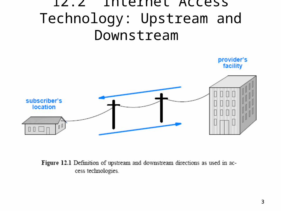
• Internet access technology refers to a data communications system that connects an Internet subscriber to an ISP – such as a telephone company(DSL) or cable company
• How is access technology designed?• Most Internet users follow an asymmetric pattern
– a subscriber receives more data from the Internet than sending• a browser sends a URL that comprises a few bytes
• in response, a web server sends content
• Upstream to refer to data traveling from a subscriber to an ISP
• Downstream to refer to data traveling from an ISP in the Internet to a subscriber
• Figure 12.1 illustrates the definitions
3
12.2 Internet Access Technology: Upstream and Downstream
3

44
12.3 Narrowband and Broadband Access Technologies
• A variety of technologies are used for Internet access• They can be divided into two broad categories based on the
data rate they provide– Narrowband– Broadband
• In networking terms, network bandwidth refers to data rate• Thus, the terms narrowband and broadband reflect industry
practice– 12.3.1 Narrowband Technologies – 12.3.2 Broadband Technologies

55
12.3 Narrowband and Broadband Access Technologies
• 12.3.1 Narrowband Technologies – refers to technologies that deliver data at up to 128 Kbps– For example, the maximum data rate for dialup noisy phone lines is
56 Kbps and classified as a narrowband technology– Figure 12.2 (below) summarizes the main narrowband access
technologies

66
12.3 Narrowband and Broadband Access Technologies
• 12.3.2 Broadband Technologies – generally refers to technologies that offer high data rates, but the
exact boundary between broadband and narrowband is blurry• many suggest that broadband technologies deliver more than 1 Mbps
• but this is not always the case, and may mean any speed higher than dialup
– Figure 12.3 (below) summarizes the main broadband access technologies

7
Narrowband vs Broadband

8
Internet connection—narrow or broadband


10
Local Loop Technologies
• Electric local loop(POTS lines): Voice, ISDN, DSL• Optical local loop: Fiber Optics services such as FiOS • Satellite local loop: communications satellite and cosmos
Internet connections of satellite television (DVB-S) • Cable local loop: Cablemodem • Wireless local loop (WLL): LMDS, WiMAX, GPRS, HSDPA,
DECT

1111
12.4 The Local Loop and ISDN • Local loop describes the physical connection between a
telephone company Central Office (CO) and a subscriber– consists of twisted pair and dialup call with 4 KHz of bandwidth
• It often has much higher bandwidth; a subscriber close to a CO may be able to handle frequencies above 1 MHz
• Integrated Services Digital Network (ISDN)– ISDN offers three separate digital channels– designated B, B, and D (usually written 2B + D)
• The 2 B channels (each 64 Kbps) are intended to carry digitized voice, data, or compressed video– Both of the B channels can be combined or bonded to produce a
single channel with an effective data rate of 128 Kbps
• The D channel (16 Kbps) is used as a control channel• Newer local loop technologies provide higher data rates at
lower cost, relegating ISDN to a few special cases• ISDN has little niche market in US, pretty popular in Japan &
Europe
1212
12.5 Digital Subscriber Line (DSL) Technologies
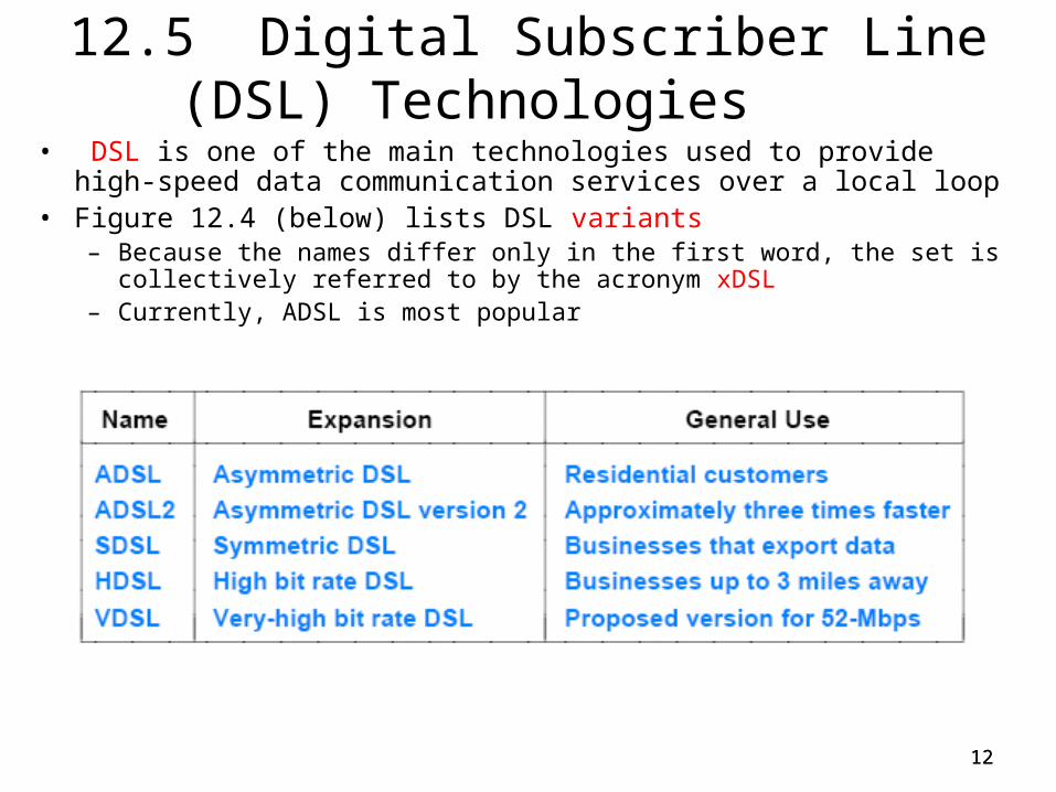
• DSL is one of the main technologies used to provide high-speed data communication services over a local loop
• Figure 12.4 (below) lists DSL variants– Because the names differ only in the first word, the set is collectively referred
to by the acronym xDSL– Currently, ADSL is most popular

1313
12.5 Digital Subscriber Line (DSL) Technologies
• ADSL is the most widely deployed variant– and the one that most residential customers use
• ADSL uses FDM to divide the bandwidth of the local loop into three regions– one of the regions corresponds to traditional analog phone service,
which is known as Plain Old Telephone Service (POTS)– and two regions provide data communication
• Figure 12.5 (below) illustrates how ADSL divides bandwidth

1414
12.6 Local Loop Characteristics and Adaptation
• ADSL technology is complex – because no two local loops have identical electrical characteristics
• ADSL is adaptive– That is, when a pair of ADSL modems are powered on, they probe
the line between them to find its characteristics– agree to communicate using techniques that are optimal for the line
• ADSL uses Discrete Multi Tone modulation (DMT)– that combines frequency division multiplexing and inverse
multiplexing techniques
• FDM in DMT is implemented by dividing the bandwidth into 286 separate frequencies called sub-channels– 255 sub-channels allocated for downstream data transmission– 31 allocated for upstream data transmission

1515
12.6 Local Loop Characteristics and Adaptation
• Two of the upstream channels are reserved for control information
• There is a separate modem running on each sub-channel, which has its own modulated carrier– Carriers are spaced at 4.1325 KHz intervals to keep the signals from
interfering with one another
• To guarantee that its transmissions do not interfere with analog phone signals– ADSL avoids using the bandwidth below 26 KHz
• Two ends assess the signal quality at each frequency– Use the quality to select a modulation scheme– If a particular frequency has a high signal-to-noise ratio
• ADSL selects a modulation scheme that encodes many bits per baud
– If the quality on a given frequency is low• ADSL selects a modulation scheme that encodes fewer bits per baud
1616
12.7 The Data Rate of ADSL
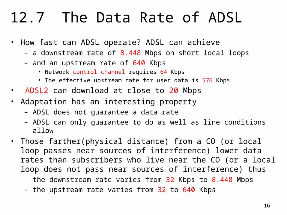
• How fast can ADSL operate? ADSL can achieve – a downstream rate of 8.448 Mbps on short local loops
– and an upstream rate of 640 Kbps• Network control channel requires 64 Kbps• The effective upstream rate for user data is 576 Kbps
• ADSL2 can download at close to 20 Mbps• Adaptation has an interesting property
– ADSL does not guarantee a data rate
– ADSL can only guarantee to do as well as line conditions allow
• Those farther(physical distance) from a CO (or local loop passes near sources of interference) lower data rates than subscribers who live near the CO (or a local loop does not pass near sources of interference) thus– the downstream rate varies from 32 Kbps to 8.448 Mbps
– the upstream rate varies from 32 to 640 Kbps

1717
12.8 ADSL Installation and Splitters
• Analog phones operate at frequencies below 4 KHz– lifting a receiver can generate noise that interferes with DSL signals
• ADSL uses an FDM device known as a splitter – It divides the bandwidth by passing low frequencies to one output
and high frequencies to another– A splitter is passive; it does not require power– A splitter is usually installed at the location where the local loop
enters a residence or business
• Figure 12.6 illustrates the connection• A variation of ADSL wiring (DSL-lite) has become popular
– it does not require a splitter to be installed on the incoming line– a subscriber can install DSL by plugging a splitter into a wall jack
and plugging a telephone into the splitter

18
12.8 ADSL Installation and Splitters
18

1919
12.9 Cable Modem Technologies
• A variety of wireless and wired technologies have been developed for use in the local loop
• An alternative access technology that uses the wiring already in place for cable television
• It is also known as Community Antenna TeleVision (CATV)• It uses FDM to deliver TV signals over coaxial cable
– CATV is not available in all countries
• Coaxial cable has high bandwidth and is less susceptible to electromagnetic interference than twisted pair
• CATV systems use FDM to deliver many channels– In CATV the bandwidth is insufficient to handle a FDM scheme that
extends a channel to each user– Using a separate channel per subscriber does not scale


21
Home Network connection

2222
12.10 The Data Rate of Cable Modems
• How fast can a cable modem operate?– In theory, a cable system can support data rates of 52 Mbps
downstream and 512 Kbps upstream.
• In practice, the rate can be much less• The data rate of a cable modem only pertains to
communication between the local cable office and the subscriber's site
• The bandwidth is shared among a set of N subscribers (the size of the set is controlled by the cable provider)– sharing the bandwidth with other subscribers can be a disadvantage
• because the effective data rate available to each individual subscriber varies over time
– if N subscribers share a single frequency• the amount of capacity available to an individual subscriber will be 1/N
23
Cable Infrastructure

2424
12.11 Cable Modem Installation
• Cable modem installation is straightforward• Cable modems attach to the cable wiring directly• The FDM hardware in existing cable boxes and cable
modems guarantees that data and entertainment channels will not interfere with one another

2525
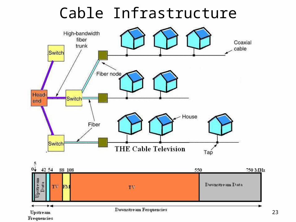
12.12 Hybrid Fiber Coax (HFC)
• HFC can provide high-speed data communications – a HFC system uses a combination of optical fibers and coaxial cables– fiber used for the central facilities and coax used for connections to
individual subscribers
• An HFC system is hierarchical– It uses fiber optics for the portions that require the highest bandwidth– and it uses coax for parts that can tolerate lower data rates
• Trunk to refer to the high-capacity connections between the cable office and each neighborhood area
• Feeder circuit to refer to the connection to an individual subscriber– Trunk connections can be up to 15 miles long– Feeder circuits are usually less than a mile

26
12.12 Hybrid Fiber Coax
26

2727
12.13 Access Technologies That Employ Optical Fiber
• There are available a variety of technologies that either employ optical fiber in a hybrid system or deploy optical fiber all the way to each subscriber
• Figure 12.8 summarizes names of key technologies

2828
12.13 Access Technologies That Employ Optical Fiber
• Fiber To The Curb (FTTC)– it uses optical fiber for high capacity trunks– the idea is to run optical fiber close to the end subscriber– and then use copper for the feeder circuits– it uses two media in each feeder circuit to allow the cable system to
provide an additional service, such as voice
• Fiber To The Building (FTTB)– it will use optical fiber to allow high upstream data rates for businesses
• Fiber To The Home (FTTH)– uses optical fiber to deliver higher downstream data rates to residential
subscribers– The emphasis is on many channels of entertainment and video
• Fiber To The Premises (FTTP)– A generic term, FTTP, encompasses both FTTB and FTTH

2929
12.14 Head-End and Tail-End Modem Terminology
• An access technology requires a pair of modems– with one at the subscriber's site and one at the provider's site
• Head-end modem to refer to a modem used at the CO– Head-end modems are not individual devices– Instead, a large set of modems is built as a unit that can be
configured, monitored, and controlled together– A set of head-end modems used by a cable provider is known as a
Cable Modem Termination System (CMTS)
• Tail-end modem to refer to a modem used at the subscriber• Data Over Cable System Interface Specifications (DOCSIS)
– specifies both the format of data that can be sent as well as the messages that are used to request services (e.g., pay-per-view)

3030
12.15 Wireless Access Technologies
• How to provide access in rural areas?– Imagine a farm or remote village many miles from the nearest city– The twisted pair wiring used to deliver telephone service to such
locations exceeds the maximum distance for technologies like ADSL– Rural areas are least likely to have cable television service
• Even in suburban areas, technologies like ADSL may have technical restrictions on the type of line they can use– it may be impossible to use high frequencies on telephone lines that
contain loading coils, bridge taps, or repeaters
• Local loop technology may not work on all lines– To handle special cases, a variety of wireless access technologies
have been explored– Figure 12.9 lists a few examples

31
12.15 Wireless Access Technologies
31

32
Wireless connections

33
Satellite connection
3434
12.16 High-Capacity Connections at the Internet Core
• Access technologies handle the last mile(sometimes called as First mile) problem– where the last mile is defined as the connection to a typical
residential subscriber or a small business
• An access technology provides sufficient capacity for a residential subscriber or a small business– the term Small Office Home Office (SOHO) is used to refer them
• Connections to large businesses or connections among providers require substantially more bandwidth
• Core refers to connections at the backbone of Internet• Core technologies refers to high-speed technologies• Figure 12.10 shows the aggregate traffic from the Internet to
the provider

35
12.16 High-Capacity Connections at the Internet Core
35

3636
12.16 High-Capacity Connections at the Internet Core
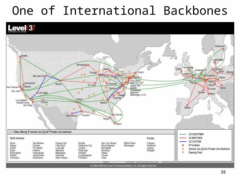
• What technology can a provider use to move data a long distance at a rate of 10 Gbps?– The answer lies in a point-to-point digital circuit leased from a
telephone company– High-capacity digital circuits are available for a monthly fee, and can
be used to transfer data
• Telephone companies have the authority to install wiring that crosses municipal streets
• A circuit can extend between two buildings, across a city, or from a location in one city to a location in another– The fee charged depends on the data rate of the circuit and the
distance spanned

37
38
One of International Backbones

3939
12.17 Circuit Termination, DSU/CSU, and NIU
• To use a leased digital circuit, one must agree to follow the rules of the telephone system– including adhering to the standards that were designed for
transmitting digitized voice
• Computer industry and the telephone industry developed independently– Standards for telephone system digital circuits differ from those used
in the computer industry– A special piece of hardware is needed to interface a computer to a
digital circuit provided by a telephone company– Known as a Data Service Unit/Channel Service Unit (DSU/CSU)
• Device contains two functional parts, usually combined into a single chassis
– The CSU portion of the DSU/CSU device handles line termination and diagnostics

4040
12.17 Circuit Termination, DSU/CSU, and NIU
• A CSU also contains a loopback test facility – that allows the CSU to transmit a copy of all data that arrives across
the circuit back to the sender without further processing
• We need to prevent excessive 1s– having too many contiguous 1 bits would mean excessive current on
the cable– To prevent problems, a CSU can either use
• an encoding that guarantees a balance (e.g., a differential encoding)
• or a technique known as bit stuffing
• The DSU portion of a DSU/CSU handles the data– It translates data between the digital format used on the carrier's
circuit and the digital format required by the customer's computer

4141
12.17 Circuit Termination, DSU/CSU, and NIU
• The interface standard used on the computer side depends on the rate that the circuit operates– If the data rate is less than 56 Kbps, the computer can use RS-232– For rates above 56 Kbps, the computer must use interface hardware
that supports higher speeds (e.g., use RS-449 or V.35 standards)
• One additional piece of equipment may be used– known as Network Interface Unit (NIU), sometimes as Smartjack
• NIU forms a boundary between equipment owned by the telco and equipment provided by the subscriber– The telephone company refers to the boundary as the demarc
• A digital circuit needs a DSU/CSU at each end– It translates between the digital representation used by phone
companies and the digital representation used by the computer industry

42
CSU/DSU for T1 connection
(T1)

4343
12.18 Telephone Standards for Digital Circuits
• A digital circuit leased from a telco follows the same digital transmission standards that the telco uses to transport digital phone calls
• In the USA, standards for digital telephone circuits were given names that consist of the letter T followed by a number– One of the most popular is known as T1– Many small businesses use a T1 circuit to carry data
• T-standards are not universal– Japan adopted a modified version of the T-series standards– Europe chose a slightly different scheme; it uses the letter E
• Figure 12.11 lists the data rates of several digital circuit standards

44
12.18 Telephone Standards for Digital Circuits
44

4545
12.19 DS Terminology and Data Rates • The data rates of T standards have been chosen so they
can each handle multiple voice calls– Note that the capacity of circuits does not increase linearly with their
numbers– For example, the T3 standard defines a circuit with much more than
three times the capacity of T1
• Telcos may lease circuits with lower capacity than those listed in the figure– they are known as fractional T1 circuits
• To multiplex multiple phone calls onto a single connection– known as Digital Signal Level standards or DS standards
• For example, DS1 denotes a service that can multiplex 24 phone calls onto a single circuit

4646
12.20 Highest Capacity Circuits (STS Standards)
• Telephone companies use the term trunk – to denote a high-capacity circuit, and have created a series of
standards for digital trunk circuits
• Synchronous Transport Signal (STS) standards specify the details of high-speed connections
• Figure 12.12 summarizes the data rates associated with various STS standards– All data rates in the table are given in Mbps, for easy comparison– Note that data rates for STS-24 and above are greater than 1 Gbps

47
12.20 Highest Capacity Circuits (STS Standards)
47

4848
12.21 Optical Carrier Standards
• Telcos define an equivalent set of Optical Carrier (OC) standards
• Figure 12.12 gives the names for optical standards as well as for copper standards
• One should observe a distinction between the STS and OC terminology:– the STS standards refer to the electrical signals used in the digital
circuit interface (i.e., over copper)– the OC standards refer to the optical signals that propagate across
the fiber
4949
12.22 The C Suffix • The STC and OC terminology described above has one
additional feature not shown in Figure 12.12– an optional suffix of the letter C, which stands for concatenated
• The suffix denotes a circuit with no inverse multiplexing– an OC-3 circuit can consist of three OC-1 circuits operating at
51.840 Mbps each– or it can consist of a single OC-3C (STS-3C) circuit that operates at
155.520 Mbps
• Is a single circuit operating at full speed better than multiple circuits operating at lower rates?– The answer depends on how the circuit is being used
• In general, having a single circuit operating at full capacity provides more flexibility – and eliminates the need for inverse multiplexing equipment

5050
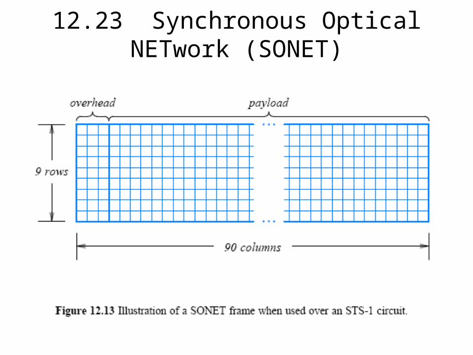
12.23 Synchronous Optical NETwork (SONET)
• Telcos defined a broad set of standards for digital transmission– In North America, the standards are known by the term Synchronous
Optical NETwork (SONET)– In Europe they are known as the Synchronous Digital Hierarchy
(SDH)
• SONET specifies some details, such as – how data is framed– how lower-capacity circuits are multiplexed into a high-capacity circuit– how synchronous clock information is sent along with data
• Figure 12.13 shows the SONET frame format used on an STS-1 circuit
51
12.23 Synchronous Optical NETwork (SONET)
51

52
SONET