1 thevenin voltage equivalents w thevenin invented a model called a thevenin source for representing...
Post on 20-Dec-2015
224 views
TRANSCRIPT
1
Thevenin Voltage Equivalents Thevenin invented a model called a Thevenin
Source for representing a complex circuit using• A single “pseudo” source
• A single “pseudo” resistance The Thevenin source, Vth, with its associated
resistance, Rth, “looks” to the load on the circuit like the actual complex combination of resistances and sources.
This model can be used interchangeably with the more complex circuit when doing analysis.
2
The Function Generator Model
Vs
FREQ = VAMPL = VOFF =
0
Rs
50
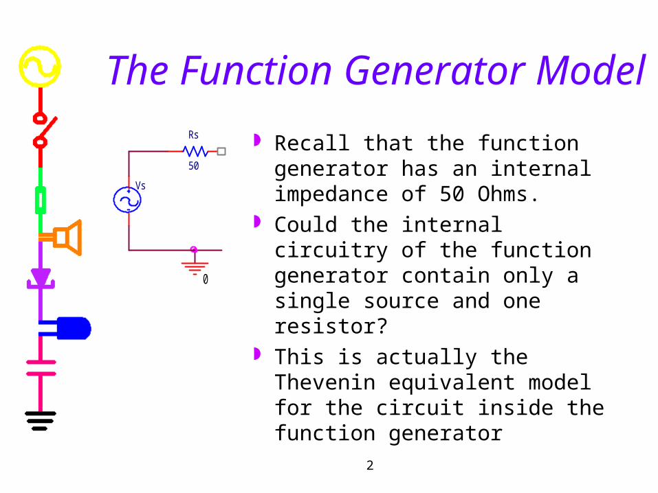
Recall that the function generator has an internal impedance of 50 Ohms.
Could the internal circuitry of the function generator contain only a single source and one resistor?
This is actually the Thevenin equivalent model for the circuit inside the function generator

3
Thevenin Model
Vs
FREQ = VAMPL = VOFF = RL
Rs
0
Load ResistorRth
Vth
FREQ = VAMPL = VOFF =
0
RL

4
Note:
We might also see a circuit with no load resistor, like this voltage divider.
R2
0
R1
Vs
FREQ = VAMPL = VOFF =

5
Thevenin Method
Find Vth (open circuit voltage)• Remove load if there is one so that load is open• Find voltage across the open load
Find Rth (Thevenin resistance)• Set voltage sources to zero (current sources to open) –
in effect, shut off the sources• Find equivalent resistance from A to B
Vth
FREQ = VAMPL = VOFF =
0
RL
Rth
A
B

6
Find Vth
Remove Load
RL
0
Vo
0Vdc
R4R2
R1 R3
0
Vo
0Vdc
R4R2
R1 R3
A AB B

7
Find Vth
Let Vo=12, R1=2k, R2=4k, R3=3k, R4=1k
V Bk
k kV
1
1 31 2 3
V Ak
k kV
4
4 21 2 8
V th V A V B V 8 3 5

8
Find Rth
Short out the voltage source (turn it off) & redraw the circuit for clarity.
0
R4R2
R1 R3
A BR3 R4
R2R1A
B
9
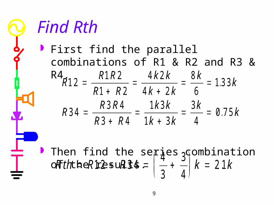
Find Rth First find the parallel combinations of R1 & R2
and R3 & R4.
Then find the series combination of the results.
RR R
R R
k k
k k
kk1 2
1 2
1 2
4 2
4 2
8
61 3 3
.
RR R
R R
k k
k k
kk3 4
3 4
3 4
1 3
1 3
3
40 7 5
.
R th R R k k
1 2 3 44
3
3
42 1.
10
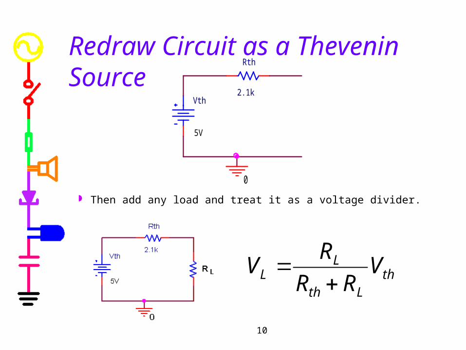
Redraw Circuit as a Thevenin Source
Then add any load and treat it as a voltage divider.
0
Vth
5V
Rth
2.1k
thLth
LL V
RR
RV

11
Thevenin Method Tricks
Note• When a short goes across a resistor, that resistor
is replaced by a short.• When a resistor connects to nothing, there will
be no current through it and, thus, no voltage across it.
R

12
Thevenin Applet (see webpage)
Test your Thevenin skills using this applet from the links for Exp 3
13
Does this really work?
To confirm that the Thevenin method works, add a load and check the voltage across and current through the load to see that the answers agree whether the original circuit is used or its Thevenin equivalent.
If you know the Thevenin equivalent, the circuit analysis becomes much simpler.
14
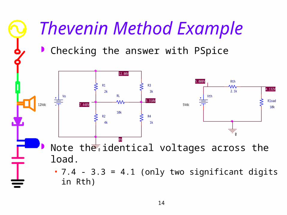
Thevenin Method Example Checking the answer with PSpice
Note the identical voltages across the load.• 7.4 - 3.3 = 4.1 (only two significant digits in Rth)
R3
3kVth
5Vdc
0
7.448V
0V
4.132V
3.310VVo
12VdcRload
10k
R1
2k
12.00V
RL
10kR2
4k
5.000V Rth
2.1k
R4
1k
0