1. technical specifications - sgcworld.com · on the ft817, a convenient place to route the switch...
TRANSCRIPT
FT817 ADSP2 Installation Low Power Board Catalog Number 70-11
SGC Inc. SGC Building, 13737 SE 26th St. Box 3526 Bellevue, WA. 98009 USA Fax: 425-746-6384, Tel: 425-746-6310 or 1-800-259-7331
E-mail: [email protected] • World Wide Web: www.sgcworld.com ©April 2003 SGC Inc
This document describes procedures that could result in voiding of the warranty of your radio.
If these procedures are not precisely and properly carried out, it could result in a radio that does not work or is damaged.
Furthermore, while reasonable efforts have been made to assure the accuracy of this information, it is possible that there are some errors, or that your radio is of a slightly different version than the one used for testing and thus, differences may exist. You are expected to take total responsibility for your own actions.
It is assumed that anyone following suggestions made in this document is already thoroughly familiar with the technologies and techniques involved and possesses the necessary skill and knowledge to make their own judgment as to the appropriateness and validity of the information.
If you choose to do the installation outlined, you do so at your own risk. You are solely responsible for any damage, voiding of warranty, or other harm that may come about by following these procedures. It is very strongly recommended that, if you maintain your own radio, you thoroughly familiarize yourself with the transceiver service manual.
If you don't have one, get one!
CAUTION: Soldering and desoldering of very small Surface Mount Components may be required to perform this installation
IMPORTANT NOTE: Support for the ADSP2 board will be provided by SGC exclusively by email. Please write to [email protected] for assistance if needed.
1. Technical Specifications
Specification Low Audio High Audio Size 1.7 X 1.475” 2.645 X 1.475” Weight 0.6 oz 1.1 oz Audio Limits Min Input 10 mv RMS 100 mv RMS Max Input 150 mv RMS 5 volt RMS Max Output .5 v RMS 9 v RMS Power Output 5 Watts RMS Current Consumption idle 80 mA 110 mA full out 80 mA 500 mA X1 X2 Noise Reduction 13 dB 26 dB Time Delay 6.5 ms 13 ms Tone Rejection -50 dB -65 dB Filters (3dB Bandwidth) Voice 300-2100 Hz CW Wide 400-900 Hz CW Narrow 600-700 Hz Out of Band Rejection -45 dB
FT817 ADSP2 Installation Low Power Board Catalog Number 70-11
SGC Inc. SGC Building, 13737 SE 26th St. Box 3526 Bellevue, WA. 98009 USA Fax: 425-746-6384, Tel: 425-746-6310 or 1-800-259-7331
E-mail: [email protected] • World Wide Web: www.sgcworld.com ©April 2003 SGC Inc
2. Preparation The ADSP2 installation provides you with an unprecedented ADSP capability, far beyond what you can find on most amateur radio transceivers.
Every possible effort has been made to provide you with a simple, easy to use product. One where you can concentrate on your communication and not on fiddling with knobs. SGC’s ADSP2 will give you years of service improving your ability to communicate.
¨ Prepare your work area
¨ Assemble your tools and parts
ADSP2 board ADSP2 switch assembly Double-stick tape for mounting the board Tools for disassembling your transceiver soldering iron suitable for working with Surface Mount Devices
3. Install the ADSP2 Board
¨ Open your transceiver
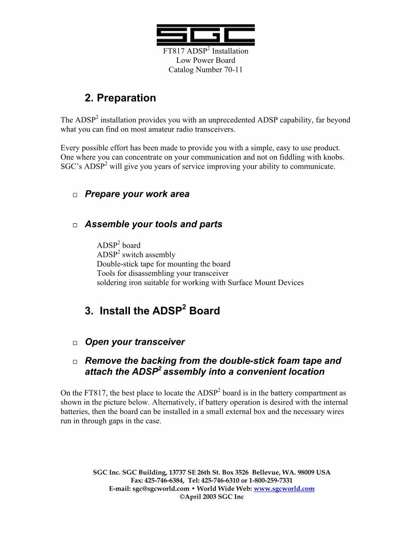
¨ Remove the backing from the double-stick foam tape and attach the ADSP2 assembly into a convenient location
On the FT817, the best place to locate the ADSP2 board is in the battery compartment as shown in the picture below. Alternatively, if battery operation is desired with the internal batteries, then the board can be installed in a small external box and the necessary wires run in through gaps in the case.
FT817 ADSP2 Installation Low Power Board Catalog Number 70-11
SGC Inc. SGC Building, 13737 SE 26th St. Box 3526 Bellevue, WA. 98009 USA Fax: 425-746-6384, Tel: 425-746-6310 or 1-800-259-7331
E-mail: [email protected] • World Wide Web: www.sgcworld.com ©April 2003 SGC Inc
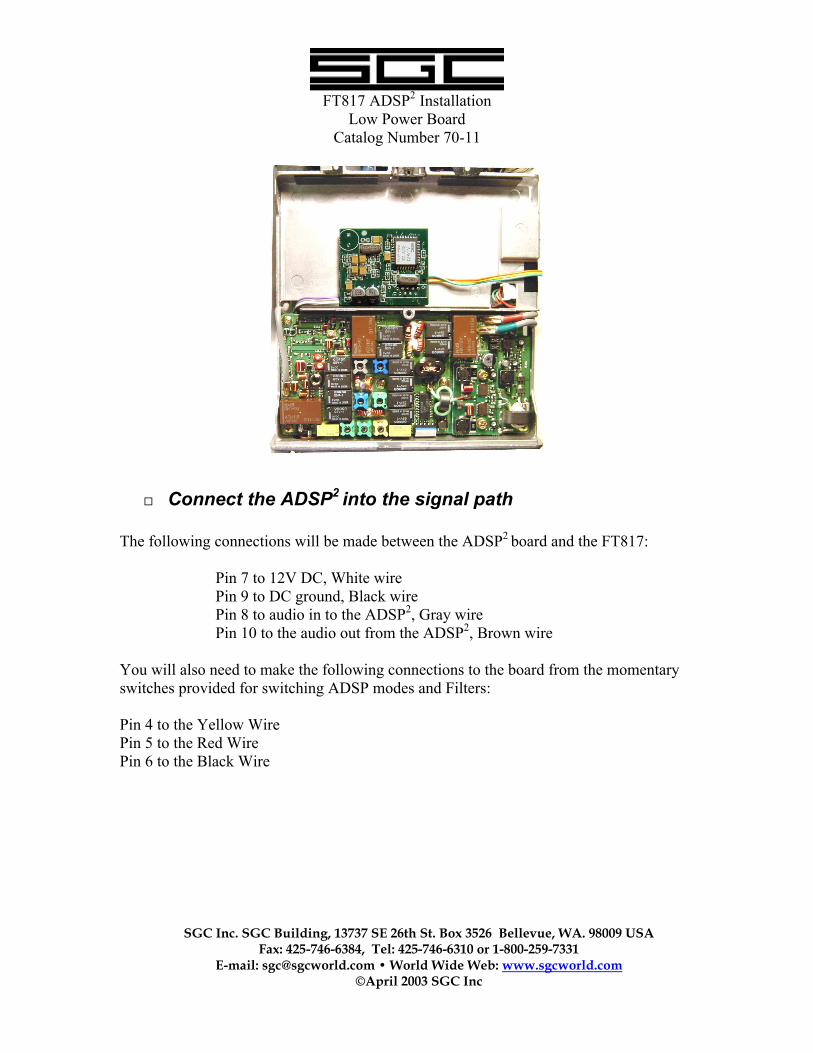
¨ Connect the ADSP2 into the signal path The following connections will be made between the ADSP2 board and the FT817:
Pin 7 to 12V DC, White wire Pin 9 to DC ground, Black wire Pin 8 to audio in to the ADSP2, Gray wire Pin 10 to the audio out from the ADSP2, Brown wire
You will also need to make the following connections to the board from the momentary switches provided for switching ADSP modes and Filters: Pin 4 to the Yellow Wire Pin 5 to the Red Wire Pin 6 to the Black Wire
FT817 ADSP2 Installation Low Power Board Catalog Number 70-11
SGC Inc. SGC Building, 13737 SE 26th St. Box 3526 Bellevue, WA. 98009 USA Fax: 425-746-6384, Tel: 425-746-6310 or 1-800-259-7331
E-mail: [email protected] • World Wide Web: www.sgcworld.com ©April 2003 SGC Inc
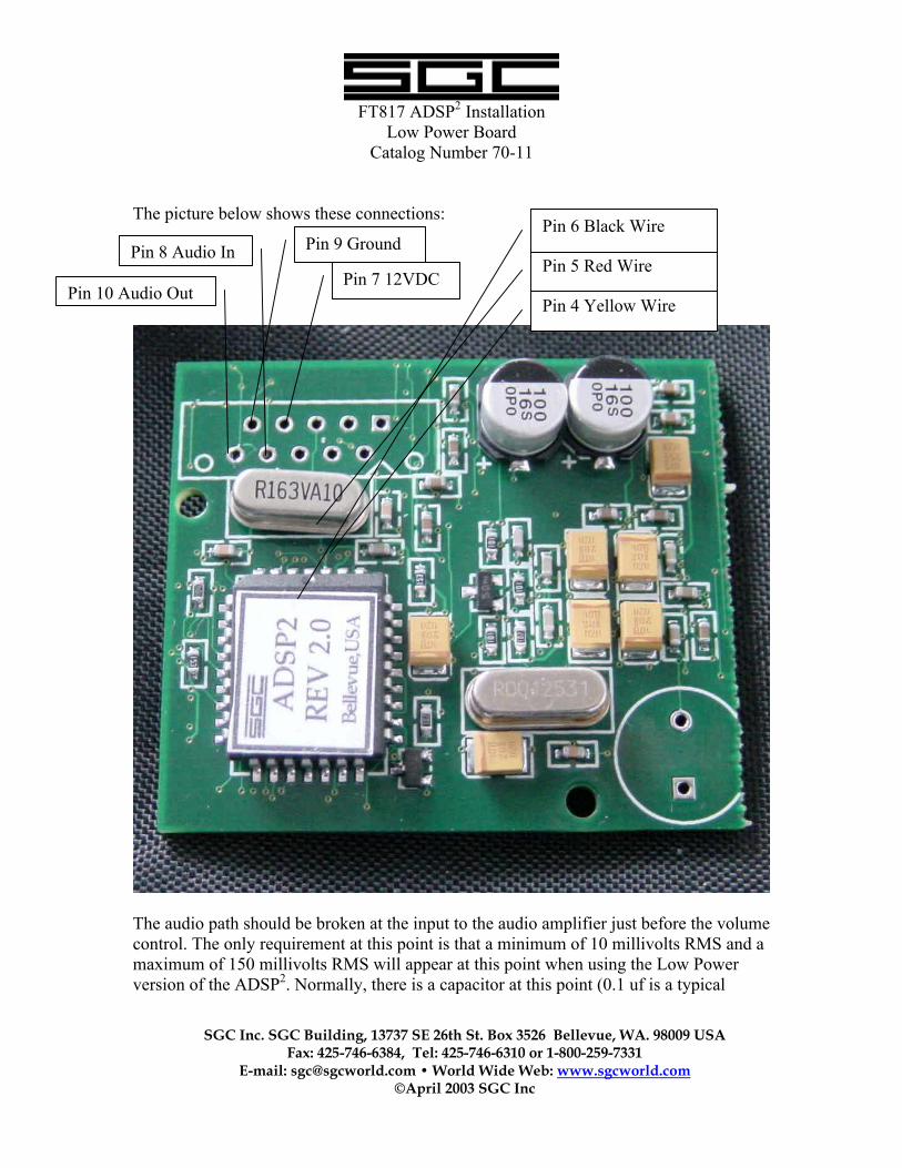
The picture below shows these connections:
The audio path should be broken at the input to the audio amplifier just before the volume control. The only requirement at this point is that a minimum of 10 millivolts RMS and a maximum of 150 millivolts RMS will appear at this point when using the Low Power version of the ADSP2. Normally, there is a capacitor at this point (0.1 uf is a typical
Pin 4 Yellow Wire
Pin 5 Red Wire
Pin 6 Black Wire
Pin 10 Audio Out
Pin 8 Audio In
Pin 7 12VDC
Pin 9 Ground
FT817 ADSP2 Installation Low Power Board Catalog Number 70-11
SGC Inc. SGC Building, 13737 SE 26th St. Box 3526 Bellevue, WA. 98009 USA Fax: 425-746-6384, Tel: 425-746-6310 or 1-800-259-7331
E-mail: [email protected] • World Wide Web: www.sgcworld.com ©April 2003 SGC Inc
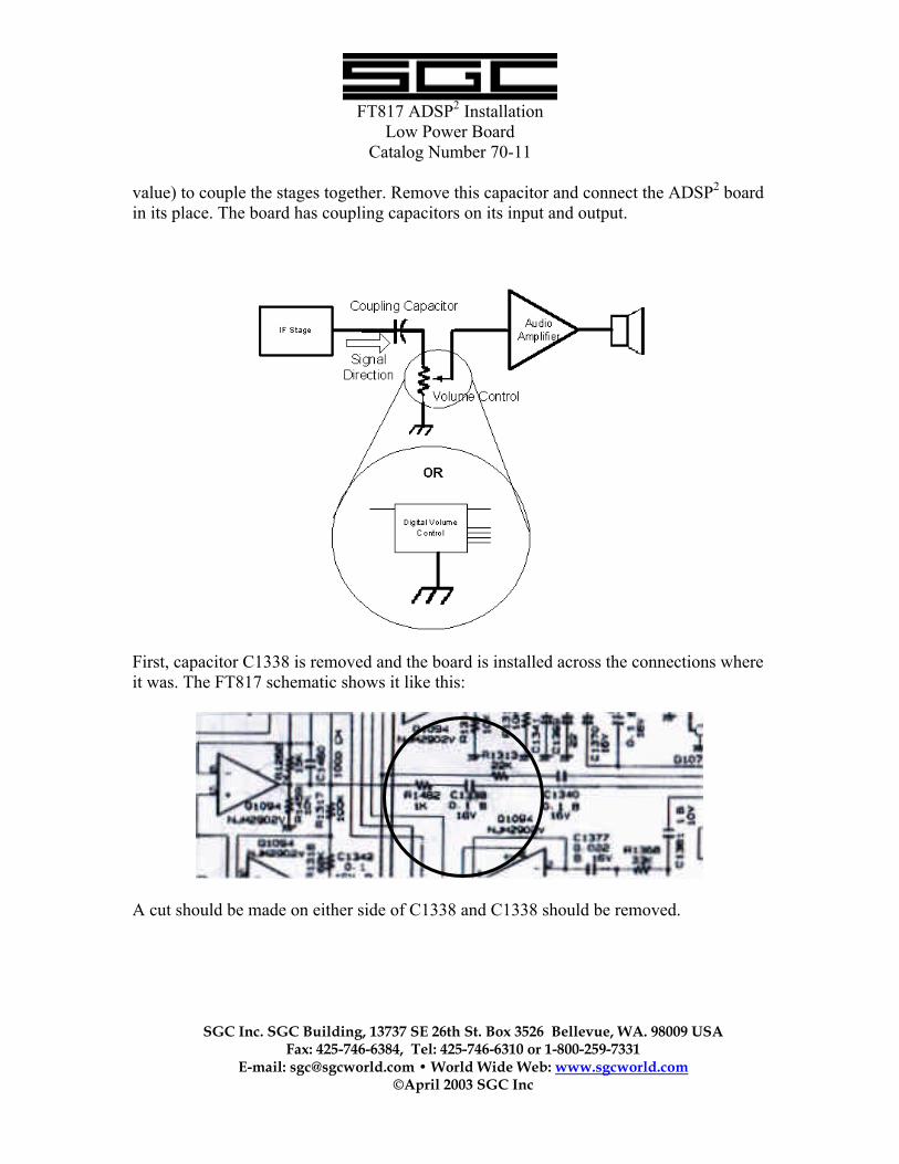
value) to couple the stages together. Remove this capacitor and connect the ADSP2 board in its place. The board has coupling capacitors on its input and output.
First, capacitor C1338 is removed and the board is installed across the connections where it was. The FT817 schematic shows it like this:
A cut should be made on either side of C1338 and C1338 should be removed.
FT817 ADSP2 Installation Low Power Board Catalog Number 70-11
SGC Inc. SGC Building, 13737 SE 26th St. Box 3526 Bellevue, WA. 98009 USA Fax: 425-746-6384, Tel: 425-746-6310 or 1-800-259-7331
E-mail: [email protected] • World Wide Web: www.sgcworld.com ©April 2003 SGC Inc
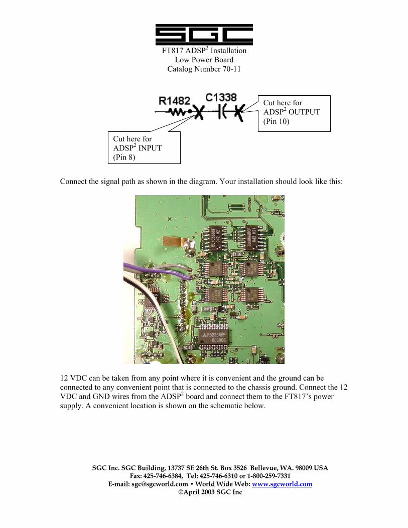
Connect the signal path as shown in the diagram. Your installation should look like this:
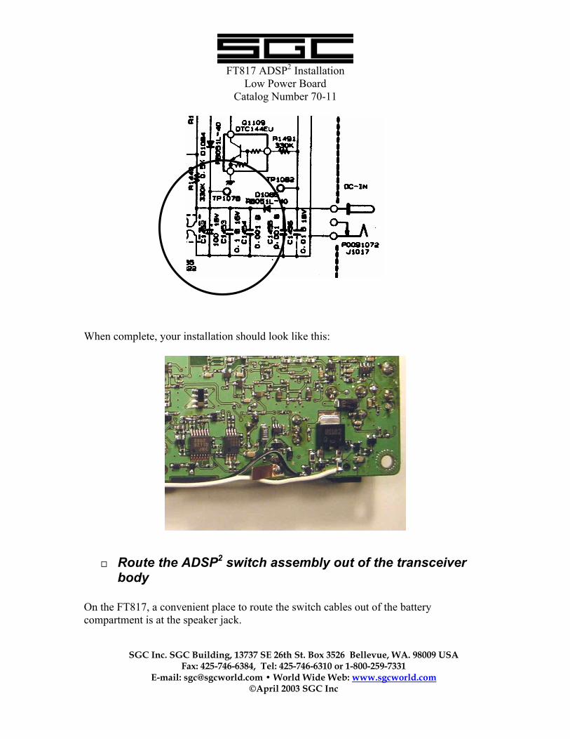
12 VDC can be taken from any point where it is convenient and the ground can be connected to any convenient point that is connected to the chassis ground. Connect the 12 VDC and GND wires from the ADSP2 board and connect them to the FT817’s power supply. A convenient location is shown on the schematic below.
Cut here for ADSP2 OUTPUT (Pin 10)
Cut here for ADSP2 INPUT (Pin 8)
FT817 ADSP2 Installation Low Power Board Catalog Number 70-11
SGC Inc. SGC Building, 13737 SE 26th St. Box 3526 Bellevue, WA. 98009 USA Fax: 425-746-6384, Tel: 425-746-6310 or 1-800-259-7331
E-mail: [email protected] • World Wide Web: www.sgcworld.com ©April 2003 SGC Inc
When complete, your installation should look like this:
¨ Route the ADSP2 switch assembly out of the transceiver body
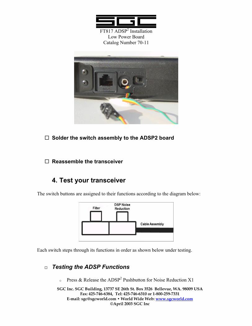
On the FT817, a convenient place to route the switch cables out of the battery compartment is at the speaker jack.
FT817 ADSP2 Installation Low Power Board Catalog Number 70-11
SGC Inc. SGC Building, 13737 SE 26th St. Box 3526 Bellevue, WA. 98009 USA Fax: 425-746-6384, Tel: 425-746-6310 or 1-800-259-7331
E-mail: [email protected] • World Wide Web: www.sgcworld.com ©April 2003 SGC Inc
¨ Solder the switch assembly to the ADSP2 board
¨ Reassemble the transceiver
4. Test your transceiver The switch buttons are assigned to their functions according to the diagram below:
Each switch steps through its functions in order as shown below under testing.
¨ Testing the ADSP Functions
o Press & Release the ADSP2 Pushbutton for Noise Reduction X1
FT817 ADSP2 Installation Low Power Board Catalog Number 70-11
SGC Inc. SGC Building, 13737 SE 26th St. Box 3526 Bellevue, WA. 98009 USA Fax: 425-746-6384, Tel: 425-746-6310 or 1-800-259-7331
E-mail: [email protected] • World Wide Web: www.sgcworld.com ©April 2003 SGC Inc
o Press & Release the ADSP2 Pushbutton for Noise Reduction X2 o Press & Release the ADSP2 Pushbutton for No Reduction o Repeat several times to verify operation
¨ Testing the Filter Functions
o Press & Release the Filter Pushbutton for the Voice Filter o Press & Release the Filter Pushbutton for the Wide CW Filter o Press & Release the Filter Pushbutton for the Narrow CW Filter o Press & Release the Filter Pushbutton for No Filter o Repeat several times to verify operation
FT817 ADSP2 Installation Low Power Board Catalog Number 70-11
SGC Inc. SGC Building, 13737 SE 26th St. Box 3526 Bellevue, WA. 98009 USA Fax: 425-746-6384, Tel: 425-746-6310 or 1-800-259-7331
E-mail: [email protected] • World Wide Web: www.sgcworld.com ©April 2003 SGC Inc
5. Installing the Switches The switches may be installed in any convenient location. The specific choice of switches was made to make it easy to mount on nearly any transceiver. Some people have chosen to install their switches on the side of the unit, others have preferred to top, and some on the front. Your specific installation will determine what the best location is. SGC welcomes any suggestions regarding these switches to improve their installation and operation. CAUTION: Overdriving the ADSP2 module may cause distortion. Backing off the level of the input signal will avoid it. SPECIAL NOTE: SGC is constantly seeking to improve the accuracy and ease of use of it’s technical documentation. Any suggestions for improving this document will be much appreciated by SGC Management.

FT817 ADSP2 Installation Low Power Board Catalog Number 70-11
SGC Inc. SGC Building, 13737 SE 26th St. Box 3526 Bellevue, WA. 98009 USA Fax: 425-746-6384, Tel: 425-746-6310 or 1-800-259-7331
E-mail: [email protected] • World Wide Web: www.sgcworld.com ©April 2003 SGC Inc

FT817 ADSP2 Installation Low Power Board Catalog Number 70-11
SGC Inc. SGC Building, 13737 SE 26th St. Box 3526 Bellevue, WA. 98009 USA Fax: 425-746-6384, Tel: 425-746-6310 or 1-800-259-7331
E-mail: [email protected] • World Wide Web: www.sgcworld.com ©April 2003 SGC Inc