1 siemens practices a30808-x5130-8120-1-8928 1 ...pdf.textfiles.com/manuals/telecom-s-z/siemens...
TRANSCRIPT

Siemens PracticesInstallation Series
:A30808-X5130-8120-1-8928
1
Issue 1, May 1986 ’1!
Issued by Office Systems Group5500 Broken Sound Boulevard N.W., Boca Raton, Florida 33431--___________-Siemcns Information Systems, Inc.
(305) 994-8100 l Telex: 515052- - - - - - ..- - - - - -
Printed in U.S.A.
SATURN IIE EPABX A 3 0 8 0 8 X 5 1 3 0 - 8 1 2 0 - 1 - 8 3 2 8Installation Test Procedures Issue 1, May 1906
SECTION PAGE
l.CO INTRDCUCTlON . . . . . . . . . . . . ; . . . . . . . . . . . . . .1-lPurpose . . . . . . . . . . . . . . . . . . . . . . . . . . . . . . . . . . l-lscope . . . . . . . . . . . . . . . . . . . . . . . . . . . . . . . . . . . . 1- lSiemens SATURN IIE Practices . . . . . . . . . . . . . . . . . l-lSiemens Customer Support Services. . . . . . . . . . . . l-l
2.00 PREP/%KGXIY ACTIVITY . . . . . . . . . . . . . . . . . . . 2 - 1Cener21. . . . . . . . . . . . . . . . . . . . . . . . . . . . . . . . . . 2 - 1Test Equipment Required. . . . . . . . . . . . . . . . . . . . 2- lHandling Precautions for PC& with
MOS Integrated Circuiis. . . . . . . . . . . . . . . . . . . . . 2- lPC6 Removal and Replacement Guidelines. . . . . . . 2 - 1Initial Visual Inspection Procedures. . . . . . . . . . . . . . 2 - 1
3.CO GROUND TESTS . . . . . . . . . . . . . . . . . . . . . . . . . . 3-lG e n e r a l . . . . . . . . . . . . . . . . . . . . . . . . . . . . . . . . . . . 3- lSystem Ground Test. . . . . . . . . . . . . . . . . . . . . . . . . 3 - 1Shelf Ground Continuity Test. . . . . . . . . . . . . . . . . . 3 - 1
4.00 POWER-UP TESTS . . . . . . . . . . . . . . . . . . . . . . . . 4-lG e n e r a I. . . . . . . . . . . . . . . . . . . . . . . . . . . . . . . . . . 4-1Power-Up/Output Voltage Tests. . . . . . . . . . . . . . . . 4- l
5.00 OPERATING PROGRAM LOAD!NG . . . . . . . . . . . . 5 - 1G e n e r a l . . . . . . . . . . . . . . . . . . . . . . . . . . . . . . . . . . . 5 - 1Loading Operafing Dis!~. . . . . . . . . . . . . . . . . . . . . . 5-lInputting CMU Data to Floppy Disk. . . . . . . . . . . . . 5- l
&CO ON-FINE DlAGrGxTlC TESTS . . . . . . . . . . . . . . . 6 - 3G e n e r a l . . . . . . . . . . . . . . . . . . . . . . . . . . . . . . . . . . . 6-lConnection of Maintenance Phone
and Modem . . . . . . . . . . . . . . . . . . . . . . . . . . . . . . 6- lMDF Cross-Connecting Prccedures. . . . . . . . . . . . . 6 - 1System Diagnostic Tests; . . . . . . . . . . . . . . . . . . . . 6-12
7.CO INSTALLATION TEST PRCCEDURES CHEC#L!ST 7-lG e n e r a l . . . . . . . . . . . . . . . . . . . . . . . . . . . . . . . . . . . 7-l
l=lGURE PAGE
2.00 Signal Cab!e Distribution for the SATURN IIESystem (Basic Cabinet). . . . . . . . . . . . . . . . .
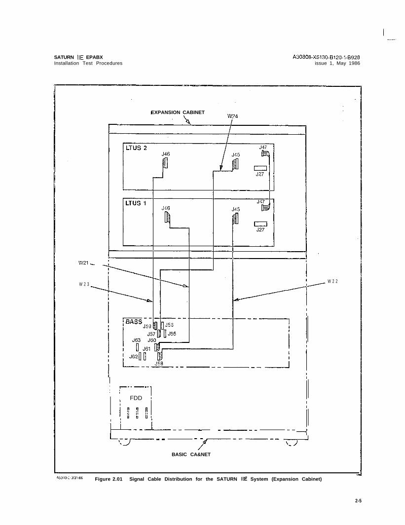
2.01 Signal Cable Distribution for the SATURN IIESystem (Expansion Cabinet). . . . . . . . . . . . .
2.02 Power/Ground Distribution for the SATURN IIESystem (Basic Cabinet). . . . . . . . . . . . . . . . .
2.03 Power/Ground Distribution for the SATURN IIESystem (Expansion Cabinet) . . . . . . . . . . . . .
3.00 System Ground Test Connections ..........3.01 Shelf Ground Continuity Test Connections. . . .4.00 Location of Input Voltage Connectors on
Basic Backplane. . . . . . . . . . . . . . . . . . . . . .4.01 Location of Input Voltage Connectors on
LTU Backplane . . . . . . . . . . . . . . . . . . . . . . .5.00 Floppy Disk and Storage Envelope . . . . . . . . .5.01 Power System Unit (Front View). . . . . . . . . . . .5.02 Floppy Disk Loading Procedures. . . . . . . . . . .5.03 CIOP Printed Circuit Board . . . . . . . . . . . . . . .6.00 Maintenance Phone and Maintenance-Related
Cress-Connections . . . . . . . . . . . . . . . . . . . .6.01 Modem Cross-Connections . . . . . . . . . . . . . . .
. 2 - 4
2 - 5
2 - 6
2 - 73 - 23 - 3
. . 4 - 5
. 4 - 65- l5-45 - 55 - 6
6 - 26-z
6.02 Single -Line Telephone Cross-ConnectionsUsing SLMA PCB . . . 6-3
6.03 Single -Line Telephone Cross-ConnectionsU s i n g SLAi6 P C B
6.04 Siemens Digital Teiephone Cross-ConnectionsU s i n g S L M D P C B . .
6.05 SATURN Attendant Console Cross-Connections6 .06 CO and CID Trunk Cross-Connec i ions .6.07 Two-Wire (Type I) E&M Trunk Cross-Connec?ions6.08 Four-Wire (T;lce I) E&M Trunk Cross-Connections
6 - 3
6 3G - 4E-5G - 5G - S_.
6.09 Two-Wire (Type II) E&M Trunk Cross-Connections . 6-66.10 Four-Wire (?ype II) E&M Trunk Cross-Connections . 6-76.i l Recorded Anncuncement (DID and Tie Trunk
Vacant Number Intercept, and ACDA n n o u n c e m e n t Service) Cross-Connect ions 6-7
6.12 Code Ca!ling (With or Without Answerback)Cross-Connections . . 6-8
6 . 1 3 D i a l C i c i a t i o n (DTMF) Cross-Conneci ions. 6-86.14 Music-en-Hold Cross-Connections Using
TMBA4 PCB . . . . 6-96.15 Music-on-Ho!d Cross-Connecticns Using
SLMAISLA16 PCB . . . . . . 6-96.16 Paging With Answerback Cross-Connections 6-106.17 Paging Without Answerback Cross-Connections. . 6-106.18 Universal Night Answer (UNA) Cross-Connections E-116.49 Attendant Conscie Keypad and Fcaturo
Button Depiassion Ssquonce G-:3620 Siemens DYIiD Te!ephono Buttcn Ccpressicn
Sequence . . . . . . . . . . . . . . 6-216.21 Siemens JR-DYAD Te!ephone Euitcn
Depression Sequence . . 6-23
1.00 Mnemonics Used in This Practice . . . . . . . . . . . . . . l-l2.CO PCB and Powar Supply Removal Guidelines . . . . . 2 - 22.01 Visual Inspeciion . . . . . . . . . . . . . . . . . . . . . . . . . . . 2 - 33.00 System Ground Test. . . . . . . . . . . . . . . . . . . . . . . . . 3- l3.01 Shelf Ground Continuity Test . . . . . . . . . . . . . . . . . . 3 - 14.00 Power-Up/Output Voitnge Test . . . . . . . . . . . . . . . . . 4- l5.00 Loading Procedures fcr Operating Disk. . . . . . . . . . 5 - 25.01 CIOP DIP Swiich Settings . . . . . . . . . . . . . . . . . . . . 5 - 35.02 LED Display Values for Leading Errors . . . . . . . . . . 5 - 46 . 0 0 T o n e G e n e r a t o r T e s t . . . . . . . . . . . . . . . . . . . . . . . . 6 - 1 36.01 Tone Genera:or Test I\!umbers . . . . . . . . . . . . . . . . G - i 36.02 DTMF Receiver Test . . . . . . . . . . . . . . . . . . . . . . . . G - 1 46.03 Station Line Test. . . . . . . . . . . . . . . . . . . . . . . . . . . 6 - 1 46 . 0 4 D T M F P a d T e s t . . . . . . . . . . . . . . . . . . . . . . . . . . . . 6 - 1 56 . 0 5 C o n s o l e T e s t . . . . . . . . . . . . . . . . . . . . . . . . . . . . . . . 6 - 1 66.06 Attendant Console Displayable Characters. . . . . . . 6 - 1 96.07 Siemens Digital Telephone - DYAD Button Test 6-206.08 Siemens Digital Telephone - JR-DYAD
Button Test . . . . .6.09 Siemens Digiial Telephone -DYAD Display Test6 . 1 0 S i e m e n s D i g i t a l T e l e p h o n e D i s p l a y a b l e
Characters . .6 . 1 1 O u t g o i n g T r u n k T e s t .6 . 1 2 P l a c i n g C i r c u i t ( s ) I n - S e r v i c e6 . 1 3 T a k i n g C i r c u i t ( s ) O u t - o f - S e r v i c e7.CO Insta!lation T e s t P r o c e d u r e s C h e c k l i s t
G-226 - 2 4
6 - 2 56 - 2 66 - 2 76 - 2 7
7- l

SATURN IIE EPABXinstallation Test Procedures
A30808-X5130-0120-l-0928Issue 1, May 1986 .
1 . 0 1 Purpose. The equipment comprising the SATURN IiE(SATURN Ii-Expanded) System is compleYely tested at the fac-tory prior to shipment. The inspections and tests covered inthis practice verify that the EPABX equipment has beenproperly installed; ensure that no damage wasIncurred dur-ing transit; and confirm that the sysiem is completely opera-tional. Table 1.00 defines the mnemonics usedthroughout ih ispractice.
CAUTION
lnstalbtion test procedures on the SATL’RN I/E EPABXmust be performed only by Siemer;s ceti i f ied personnel.
1 . 0 2 Sccpe. This practice is divided into the following sec-tions which are presented in the sequential order of per-for-mance after initial installation of a SATURN IIE System. Whenadditional equipment is installed to an existing and activeSATURN IIE System, it is the responsibility of craft person-nel to determine the sequential order of the test procedurescontained in tihese sections.
ACD Au;omai ic Cafl DisiributionALiVl AlarmASCII American Standard Code for Information lntarchangeCIOP Controller/Input-Ouiput PrccessorCMU Customer Memory Updatec o Central OfficeCONF Conference ModuleC O T Central Office TrunkDCI Data Communication InterfaceDID Direct Inward DialingD I P Dual lnline PackageD P Dial PulseD T E Da?a Terminal EquipmentD T M F Dual Tone MultifrequencyE I A Electronics Industries AssociationE P A B X Electronic Private Automatic Branch ExchangeFDD Floppy Disk DriveIRAM Input Random Access MemoryL T U Line/Trunk UnitL T U P S Line/Trunk Unit Power SupplyLED Light-Emitting DiodeMCA Memory Control and AttenuationMDF Main Distribution FrameMEM3 25Gkb MemoryMEM4 1Mb MemoryMOS Metal Oxide SemiconductorMRA Material Return Authorization.M S M Memory Support ModuleM T C E Maintenance00s Out-of-ServiceORAM Output Random Access MemoryP A B X Private Automatic Branch ExchangePCB Printed Circuit BoardP E N Port Equipment NumberPIMD Premium Instrument Module DigitalPSC Parallel/Serial ConverterPSU Power Supply Unit
a. Section l.CO - Introductionb. Section 2.00 - Preparatory Act ivi iyc. Section 3.00 - Ground Testsd. Section 4.00 - Power-Up Testse. Section 5.00 - Operating Program Loadingf. Section 6.80 - On-Lina Diagnostic Tesisg. Section 7.00 - lnstallaticn Test Procedures
Checklist
7 . 0 3 Siemens SATURN IIE Prac:iccs. The practices, issuenumbers and dates for the SATURN IIE EPABX are lists3 in theP r a c t i c e s D o c u m e n t a t i o n I n d e x A.30808~X5130-AlgO- * -E987 A l -ways refer to the !aiest issue of the application indcx to ob-tain the latest issue number of a practice.
724 S iemens Cus;oma: Sqpsrt Serv ices. Sicrnonsmaintains a nationwide network cf field service offices. Con-tact the Siemens regional oif ice for any engineering es-sistance that may be requked.
TaS!e 1.00 Mnemonics Used in This Practice
DEFiN1TfON
i - i

SATURN IIE EPABXInstallation Test Procedures
.
Table 1.00 Mnemonics Used in This Practice (Continued)
[\fiNEMDNIC * D E F I N I T I O N
R A U P Remote Access Unit/PortsRGEN Ring GeneratorS-416 Subscriber Line Module Analog - 16 linesSLMA Subscriber Line Module AnalogSLMA-S Subscriber Line Module Analog - StationSLMD Subscriber Line Module DigitalS M X T G Signal Multiplexer/Tone GeneratorSPC Stored-Program-ControlledS P G Single Point GroundTMBA-2 Two-Wire E&M TrunkTMBA-4 Four-Wire E&M TrunkTMBM Central Office TrunkTMIE Direct Inward Dialing TrunkTMS Transmission Measuring SetT S T A P P Test - ApparatusTSTDIAG Test - Maintenance DiagnosticT T Y TeletypewriterUNA Universal Night AnswerZUNA Zoned Universal Night Answer-48PS -48Vdc Power Supply
l-2 (2 pages)

SATURN IIE EPABX A30808-X5130-B120-l-8928Installation Test Procedures Issue 1, May 1986
2 . 0 1 General. This section describes the test equipment re-quired to perform the installation test procedures, handlingprecautions for Printed Circuit Boards (PCBs) with Metal Ox-ide Semiconductor (MOS) integrated circuits, guidelines forremoval and replacement of PCBs and powei supplies, andinitial visual inspection procedures.
2.02 Test Equipment Required. The following test equip-ment is required to perform the procedures contained in thispractice:
a. Digital Multimeter. A digital multimeter of gocd com-mercial quality with an accuracy of + 1.0% or better.The digital multimeter is used to perform the groundtests and output voltage tests.
b . Maintenance Test Phone. For both Dial Pulse (DP) andDual Tone Multifrequency (DTMF) systems, a lineman’stest set or a single line te!ephone. A modular jack(MTCE PHONE) is provided on the front panal of thePSU for conneci ing the maintenance test phone whenequipped with a modular plug. When the maintenancetest phone is not equipped with a modular plug, a sta-tion appearance can be used via the Main Distribu-tion Frame (MDF). The mainienance test phone is usedto perform the on-line diagnostic tests.
c. Data Service Terminal. A Keyboard-Send-Receive(KSR) daia terminal equipped with a standard ASCIIkeyboard and an EIA RS-232C interface (Silent 700Series - Model 743 KSR - Texas Instruments, orequivalent). The data service terminal is used to inputinstallation dependent data (i.e., system data base) intosystem memory when the standard data base formatis supplied with the SATURN IIE System.
d. -Transmission Measuring Set. A transmission measur-ing set (TMS) used to measure the transmission qual-ity of a trunk or station (Hewlett Packard HP-355iA orequivalent). Refer to the manual On-Line DiagnostiCTests, Outgoing Trunk Test and Station Line Tosl.
2.03 handling Precautions for PCBs wifh MCS Integmt-ed Circuiklt is important that craft personnel handling FCBswith MOS integrated circuits free themselves from electrostaticcharge by touching a grounded cabinet frame before handlingsuch PCEs, or by wearing grounded wrist straps. Failur:, toobserve this practice may result in damage to MO3 PCBsdue to electrostatic discharge.
WARNING
lirazardous voltages exist r&h.% the eqo&ment cabins?.B e e x t r e m e l y c a r e f u l w h e n perr”orming fcsa-incjtroubleshooting procedures with the oquipmcr;tpanel(s) removed.
2 . 0 4 PCB Removal and P,ep!acemenZ Guide%% In manyinstances during testing, the corrective action for a procedurein which the proper verification was not obtained requires thata PCB or a power supply be removed and replaced with aspare. Tablo 2.00 provides the guidelines that shou!d be o!)-served when removing and rep!acing PCBs and powor SI:;X-plies in an active sysicm.
2.05 lnifial Visual kspactizn Procedurx. The visu’al in-spection procedures contained in Tab!e 2.01 must be psrfcrmcdto ensure that the equipment comprising the SATURN ItE Sys-tem has been properly installed and configured to meet theinstallation requirements. Before proceeding wiih the visual in-spections, the front, rear and side panels of the cabinei shouldbe removed to allcw thorough inspection of the equipment.
2 - 1

-
Table 2.00 PC3 and Power Supply Remcval Guidelines
I’AODIJLE OR SERVEC” SPECIALUNIT S T A T E INSTRUCTKWIS
CIOP NACONF . NADTMF 0 0 sFDDO, FDDl NALTUC f NAL T U P S l NAMCAMEM3 kzMEM4 NAM S M l NAMSM Baitery l NAPIMD 0 0 sPSC NAPSU NARAUP NASLAl6 00sSLMA-0 0 0 sSLMA-S 003SLMD 0 0 sS M X T G
ESTMBA-2TMBA-4 0 0 sTMBM 0 0 sTMIE 0 0 s-48PS.l NA-48PSt f NA
* Optional depending upon customer/system requirements.NA = Not Applicable; 00s = Out-of-Service
Notes 1 and 2Notes 1 and 2Note 3NoneNote 4Note 5Notes 1 and 2Notes 1 and 2Notes 1 and 2Note 1Note 6Note 3Notes 1 and 2Note 7Notes 1 and 2Note 3Note 3Note 3Note 3Notes 1 and 2Note 3Note 3No?e 3Note 3Note 8Noie 3
Notes:
1 . System outage (halts call processing). Set BASIC PS circuit breaker on PSU to off.2 . Open FDD and remove floppy disk before removing PCB. After new PCB is inserted, reinsert floppy disk, close
FDD, set BASK PS circuit breaker on PSU to on, and press reset switch on CIOP3 . VVait for in-process ca! ls i0 complete.4 . Removal places one-half of ports in shelf out-of-service.5 . Before removal, set related LTUPS circuit breaker on PSU to off. Removal places all ports in shelf out-of-service.6 . Battery may be replaced with power applied to system.7. System outage (halts call processing). Before removal, set all circuit breakers to off, open FDDs and remove flop-
py disks. After replacement, reinsert floppy disks, close FDDs, set circuit breakers to on, and press reset switchon CIOR
8 . Set related circuit breaker on PSU to off. May halt call processing depending upon system configuration andtraffic. If there are two -48Vdc power supplies (where system includes an Expansion Cabinei), the remaining sup-ply may have sufficient capacity to support system operation.
A30808-X5130-8120-l-8928Issue 1, May 1986
2 - 2

I .-
A30808-X5130-B120-l-8928Issue 1, May 1986
SATURN IIE EPABXInstallation Test Procedures
Table 2.01 Visual Inspection
S T E P VISUAL INSPECTION REFERENCE
1 Check that the cabinet ac power cord is not connected to anelectrical outlet.
2 Check that the -48Vdc power supply is strapped for SATURN IIE EPABX Installation11OVac or 22OVac. Procedures Practice (Section 4.00)
3 Check that all circuit breakers on the Power System Unit SATURN IIE EPABX Installation(PSU) are in the OFF position and fuses inserted. Procedures Practice (Section 4.00)
4 If the MSM is installed, check that the Battery Packk is not SATURN IIE EPABX Installationconnected but inserted into corresponding position. Also Procedures Practice (Section 4.00)check that the PSU is strapped for MSM operation.
5 Check that each PCB in the system is withdrawn from itsbackplane connector.
6 Check that the DIP switch settings for the CIOP board are set SATURN IIE EPABX Installationto meet the operating characteristics of the particular data Procedures Practice (Section 4.00)service terminal to be used to input the installation-dependentdata(i.e.,data base) into system memory when the standarddata base format is supplied with the SATURN IIE System.
7 Check that each trunk-type PCB (i.e., T M E M , TMIE, TMBA-2 SATURN IIE EPABX Installationand/or TMBA-4) is properly strapped according to the Procedures Practice (Section 4.00)operating characteristics of the trunk facility of the CentralOffice (CO) or distant PABX.
8 Chec!c that the intercabinet signal and power/ground cabling Figures 2.00 through 2.03arrangements are complete and all connectors are firmly seat-ed according to the referenced illustrations (Figures 2.00through 2.03).
9 Check that Berg Clips are on pins 27 and 28 of unused SATURN IIE EPABX Installationsignal cable connectors on basic shelf. Procedures Practice (Section 4.00)
2 - 3

w 3 w13
-
I I
SATURN IIE EPABX,xtal lat ion Test Procedures
A30808-X5130-B120-l-5928Issue 1, May 1986
Figure 2.00 Signal Cable Distribution for the SATURN IIE System (Basic Cabinet)
SATURN IIE EPABXInstallation Test Procedures
A30808-X5130-B120-l-8928issue 1, May 1986
W 2 3
EXPANSION CABINET\
I --- ---: ] 1
FDD :
, i;wi!
i-L--i-- - _-__ --LiTJ-. - - -r----- *
W 2 2
BASIC CA&NET
A5040-2.313186 Figure 2.01 Signal Cable Distribution for the SATURN IIE System (Expansion Cabinet)
2-5

SATURN IIE EPABXtnstallation Test Procedures
A30808-X5130-8120-1-8928Issue 1, May 1986
LTUSOLINE TRUNK UNIT SHELF J42
J43r JPL
Jl
BASSBASIC SHELF
E l a - - - -J46
J47
E2
05039.1..wmG Figure 2.02 Power/Ground Distribution for the SATURN IIE System (Basic Cabinet)
2-6

A30808-X5130-B120-l-8920Issue 1, May 1986
EXPANSION CABINET REF.
L--M--e--\- - - - -,-,- - - - - -
- - - - -
BASIC‘CABINET REF.
A5U38-1-4:3:86 Figure 2.03 Power/Ground Distribution for the SATURN IIE System (Expansion Cabinet)
2-7 (2-8 blank)

SATURN IIE EPABX A30808-X5130-B120-l-8928Installation Test Procedures issue 1. May 1986
3 . 0 1 General. The SATURN HE System must be connectedt o a n e a r t h g r o u n d ( i . e . , m e t a l l i c c o l d w a t e r p i p e o r m a s t e r g r o u n dbusbar) in addition to the safety ground in the ac power cord.A G-gauge (twisted copper wire) conductor should be connect-e d b e t w e e n t h e g r o u n d i n g l u g E 5 l o c a t e d o n t h e b o t t o m o f t h ecabinet frame and the snlccted earth ground (refer to Section3.00 in the SATURN HE EPABX Installation Procedures prac-tice for details). The following tests must be performed to en-sure that proper earth ground connections have beenaccomplished, and that ground connections within the cabineta s s e m b l y h a v e n o t b e e n d a m a g e d o r l o o s e n e d d u r i n g s h i p m e n t .
WARNiNG
Hazardous voltsgos txkt within the equipment csbinef. Ee
extremely ca-ej’Ll when performing t~s%i~g/l’roubiesh~otingprocedures with the equipment panel(s) removed.
3 . 0 2 System Grcund Test. Before proceeding with the test’procedures indicated in Table 3.00, check that the earthground connections are secure and ground conductors arefirmly positioned on grounding lug E5 at ihe bottom of thecabinet frame.
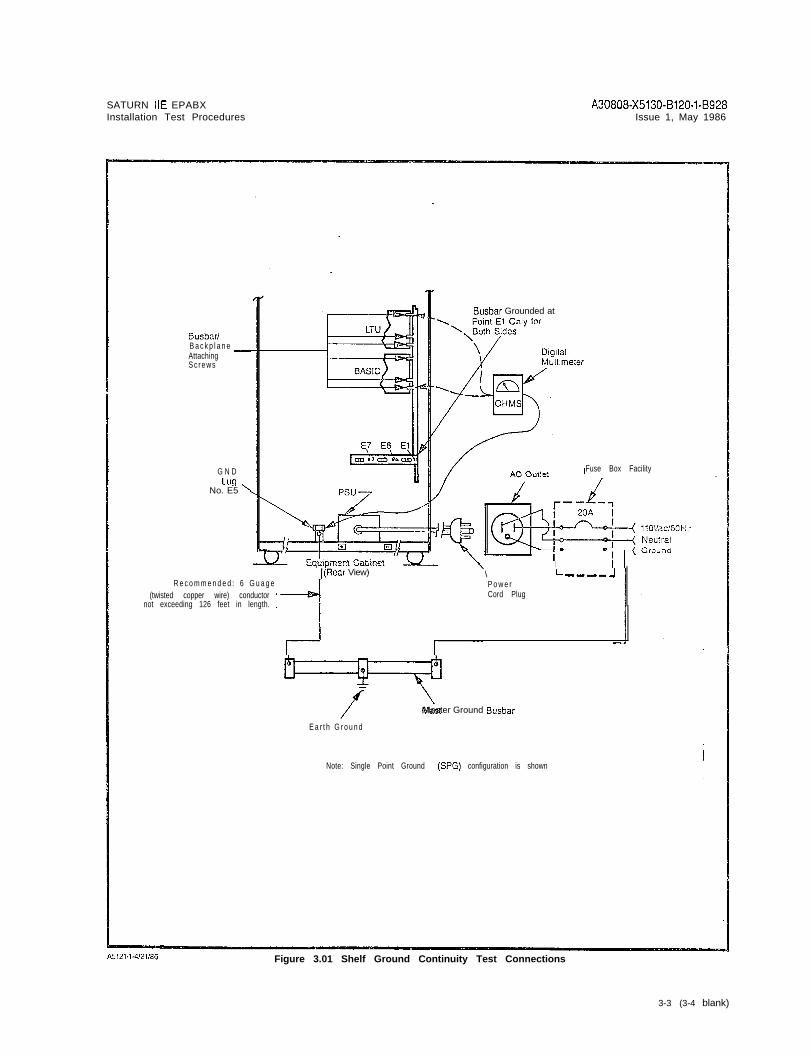
3 . 0 3 Shelf Ground Continuity Test. Each LTU shelf assem-bly within the cabinet assembly is grounded via two verticalbusbars. Beiore proceeding with the test procedures indicat-ed in Table 3.01, check that each shelf backplane is iniercon-netted with the busbar flanges and adequately secured intoposition.
Table 3.00 System Ground Test
PROCEDURE VERlFlCATlON IF VERlFlCATIONIS NOT OBTAINED
.l If connected, remove ac power cordfrom commercial power outlet.
2 Short digital multimeter tesi leadstogether and noie resistance of testl e a d s .
3 Set digital multimeter to lowest Resistance measured should be If a reading greater ihan 2 ohms isresistance range and connect its betweem 0 and 2 ohms greater than obtained, the faulty ground con-leads between the U-ground pin of the measured test lead resistance. nection must be isolated and cor-the ac power cord and the U-ground rected befora continuing wi?h thesocket in the commercial power installation test procedureso u t l e t ( r e f e r t o F i g u r e 3 . 0 0 f o r d e t a i l s ) .
4 Repeat procedure with second ac Same as step 3 above. Same as step 3 above.power cord if optional expansioncabinet is incorporated into system.
Table 3.01 Shelf Ground Continuity Test
STEP PROCEDURE VERIFICATION IF VERIFICATiONIS NOT OBTAINED
1 If connected, remove ac power cordfrom commercial power outlet.
2 Set digital multimeter to lowest Resistance measured should be If a reading greator than 1 ohm isresistance range and connect its between 0 and 1 ohm greater than obtained, the faulty ground connec-leads between ground lug E5 located the measured multimeter test lead tion must be corrected before con-at the bottom of the cabinet frame, resistance. tinuing the installation test pro-and one of the busbar/backplane cedures.attaching screws for each existingLTU shelf (refer to Figure 3.01)
3- l

SATURN IIE EPABX A30808-X5130-B120-l-8928Installation Test Procedures Issue 1, May 1986
BASIC CabinetG N DL U G
F u s e B o x Facility
(ES) ,
5, B D
Power co
PSUf llOVAC~$GOi-fZ
El El NeulralG r o u n d
hlatn Cabmel(Rear View)
R e c o m m e n d e d : B - g a u g e(iwtsted Copper Wire)
conductor not exceedmgi26 feet m length.
I (Ootlonall
I.1
fMaster Ground Busbar
Earth Ground Note: Single Point Ground (SPG) configuration IS shown
Figure 3.00 System Ground Test Connections
3 - 2
SATURN IIE EPABXInstallation Test Procedures
A30808-X5130-8120-1-8928Issue 1, May 1986
Busbar/B a c k p l a n e -AttachingS c r e w s
G N DLug
No. E5 ’
7-
R e c o m m e n d e d : 6 G u a g e(twisted copper wire) conductor
not exceeding 126 feet in length.
I(Rear View)
Busbar Grounded at
Fuse Box Facility
\IL ---_ -I
P o w e rCord Plug
7Master Ground Busbar
E a r t h G r o u n d
Note: Single Point Ground (SPG) configuration is shown
Figure 3.01 Shelf Ground Continuity Test Connections
3-3 (3-4 blank)

I -_
SATURN IIE EPABXinstallation Test Procedures
A30808-X5130-BlZO-l-8928Issue 1, May 1986
SECTION 4.00 POWER-UP TESTS
4 . 0 1 General. The SATURN IIE System makes use of dis-tributed power in the equipment cabinet. Several power sup-plies are used in the system. These power supplies provide+5Vdc, -SVdc, +12Vdc, -12Vdc, -48Vdc, 90Vac-20Hz ringingvoltage and message waiting voltage, from a 11OVac 60Hzinput power source. After satisfactorily performing the groundtests indicaied in Section 3.00, the following tests must be per-formed to ensure that proper power cable connections havebeen accomplished and that the power supplies inside thecabinet assembly have not been damaged during shipment.
WARNING
Hazardous voltages exist within the equipment cabinet. Beextremely careful when performing testin@roubkshootjng’pmcedures with the equipment panel(s) removed.
4 . 0 2 Power-Up/Output Voltage Tests. Before proceeding withthe test procedures indicated in Table 4.00, check that all pow-er cable assemblies are properly secured into their correspond-i n g l o c a t i o n s . N o t e t h a t t h e t e s t p r o c e d u r e s i n T a b l e 4 . 0 0 i n c l u d ep r o c e d u r e s f o r t e s t i n g t h e o p t i o n a l M S M , w h e n e q u i p p e d i n t h esystem.
Table 4.60 Power-Up/Output Voltage Test
YiEP PROCEDtJRE
f not previously done, extract each‘CB in the system from its respec-ive backplane connector in basicmd LTU shelves.
Check that all circuit breakers on the‘SU are in the off positions and that311 fuses are inserted in their cor-,esponding locations.
Jsing the digital multimeter (or an3c polarity indicator), verify that the:ommercial ac power receptacleJsed for powering the systsm has theIroper polarity.
Connect the ac power cord(s) to thezommercial ac power receptacle(s).
?lace the following circuit breakerson the PSU to the on (up) position:
a) Basic PSb) -48PSOc) -48PSl (if equipped)d) LTUPSO (if equipped)e) LTUPSl (if equipped)9 LTUPS2 (if equipped)
If the optional MSM module isequipped in the system, proceed 2sfollows:
2) If not previously done, connectand insert battery pack intothe MSM assembly.
b)Press the BATTERY TESTswitch on the PSU andrelease after verification hasbeen obtained.
VERIFICATION
‘olarity indication must coincide with=igures 3.00 and 3.01.
The associated green LED shouldlight steadily.
IF VERIFICATIONIS NOT 08TAlNED
if polarity indication does not coin-cide, correct before proceeding withthe remainder of test in this lable.
If the green LED remains cxtin-guished, the battery pack is belowacceptable voltage limits. Let MSMcharge battery pack and retry test af-ter 30 minutes have elapsed. If greenLED remains extinguished, the bat-tery pack is defective and requiresreplacement.
‘l-1

SATURN IlE EPABXInstallation Test Procedures
A30808-X5130-8120-1-8928issue 1, May 1986
Table 4.00 Power-Up/Output Voltage Test (Continued)
SE? PROCEDURE VEfiIFICATION IF VERIFICATIONIS NOT OBTAINED
c) On the PSU, place the circuit The red LED designated BATTERY If the red LED remains extinguished,breaker designated BASIC PS TEST.should be steadily lit. replace the MSM.in the off (down) position.
The red BATTERY TEST LED should1d) On the PSU, place the circuit If the red LED remains steadily lit,
breaker designated BASIC PS be extinguished. either the cabinet ac power cord isto the on (up) position. not connected to the commercial ac
power receptacle or a local ac pow-er failure has occurred.
7 Set digital multimeter to appropriate N O T Edc voltage scale for the following If further troubleshooting informationtests. is required during these testing
procedures, refer to SATURN IIEEPABX Maintenance andTroubleshooting Practice.
8 A To measure the unloaded basic shelfinput voltages, proceed as follows:
a) On basic backplane shown in Voltage measured should read be- If reading is not within tolerance, ad-Figure 4.00, take reading be- tween +4.5 and +5.5 Vdc. just +5V ADJUST potentiometer ontween terminal El, E2, E3 or PSU. If still out-of-tolerance replaceE4 and ground. PSU.
b) On basic backplane connector Voltage measured should read bo- If reading is not within to!erance,J46, shown in Figure 4.00, take tween -43 and -53Vdc. check the -48P-BASIC fuse in PSU.readings beiween pins 2 and 3. If fuse is good, replace -48PSO.
c) Set digital multimeter to ap- Voltage measured should be be- If the voltage is not present, checkpropriate Vat scale and take tween 75 and 100 Vat. and replace RGEN fuse or RAC BAS-reading between pins 1 and 2 IC fuse on PSU. If fuses are good,of J46. r e p l a c e R G E N P C B . I f v o l t a g e s t i l l n o t
present, replace PSU.
d ) S e t d i g i t a l m u l t i m e t e r t o a p p r o p r i -ate Vdc scale and take readingsbetween the following pins onbasic backplane connector J47(shown in Figure 4.00):
1) Pins 1 and 3.
2) Pins 2 and 3.
Voltage measured should be be- If reading is not within tolerance,tween -4.9 and -5.2Vdc replace the PSU.
Voltage measured should be be- If reading is not within tolerance,tween -43 and -53Vdc check the -488 BASIC fuse on PSU.
If the fuse is good, replace -48PS0.
e) On basic backplane connectorJ48, shown in Figure 4.00, takereadings between the followingpins:
1) Pins 1 and 4.
2) Pin 2 or 3 and pin 4.
3) Pins 4 and 5.
Voltage measured should read be- If reading is not within tolerance,tween -11.3 and -12.7Vdc. replace the PSU.
Voltage measured should be be- If reading is not within tolerance,tween +11.3 and +12.7Vdc. replace the PSU.
Voltage measured should be be- If reading is not within tolerance,tween 4.85 and 5.15Vdc. check that J16 on the rear panel of
the PSU is strapped to the MSM ter-minal. If the strap is in place, replacethe MSM.

I -
SATURN IIE EPABXInstallation Test Procedures
A3G808-X5130-B120-1-B928Issue 1, May 1986
lbb!c 4.00 Power-Up/Output Voltage Test (Continued)
S T E P FROCEDUEE V E R I F I C A T I O N IF VERIFICATIONIS NOT OBTAINED .
f) Connect positive lead of digital Voltage measured should read + If reading is not 0.05 Vdc, adjust +5Vmultimeter to pin 5 of connec- 0.05Vdc. ADJUST potentiometer on PSU. Iftor J48 and negative lead to adjustment is not effective, replaceterminal El on basic back- PSU.plane. (Refer to Figure 4.00.)
813 After satisfactorily completing step8A, proceed as follows to measurethe loaded basic shelf input voltages.
a) On the PSU, place the circuit The MSM red LED designated BAT-breaker designa?ed BASIC PS TERY TEST should be steadily lit.in the off (down) position.
b) Plug all previously extractedPCBs on the basic shelf intotheir respective backplaneconnectors.
c) On the PSU, place the circuit The MSM red LED designated BAT-breaker designated BASIC PS TERY TEST should be extinguished.in the on (up) position.
d) Repeat measuring procedures Same verification as in steps 8A a)on basic backplane connectors through e), except that -t-S!/& at ter-J46, J47, J48 and terminals minal El should read between 4.85El-E4 as indicated in step 8A. and 5.15Vdc under load.
9A To measure the unloaded LTU shelfi n p u t v o l t a g e s ( i f a p p l i c a b l e ) , p r o c e e das follows:
a) On the LTU backplane con-nector J42,shown in Figure4.01,take a reading betweenthe following pins:
1) Pins 1 and 3. Voltage measured should be be- If reading is not within to!e:ance, ad-tween +4.5 and +5.5Vdc. just +5V ADJUST potentiometer on
LTUPS. If the adjustment does notbring voltage into tolerance,replaceL T U P S .
2) Pins 3 and 5.
3) Pins 3 and 4.
Voltages measured should be be- If reading is not within tolerance,tween -4.9 and -5.2Vdc. replace appropriate LTUPS.
Voltage measured should be be- If reading does not coincide withtween -43 and -53Vdc. verification reading, check the -48P
LTU fuse on PSU. If fuse is good,replace -48PS0.
4) Set digital multimeter toread Vat and connect be-tween pins 2 and 3.
Vo l t age measu red shou ld be be - I f vo l t age i s not p resent ,tween 75 and 1OOVac. check/replace RGEN fuse or RAC
LTUO fuse on PSU. If fuses are good,replace PSU.
b) Set digital multimeter to ap-propriate Vdc scale.
C) On LTU backplane connectorJ43,shown in Figure 4.01, takea reading between the follow-ing pins:
4 - 3

SATURN IIE EPABXInstallation Test Procedures
A30808-X5130-B120-l-6928Issue 1, May 1986
Table 4.00 Power-Up/Output Voliagc? Test (Continued)
S T E P PROCEDURE VEFllFlCATlON IF VERIFICATIONIS NOT OBTAINED
1) Pins 1 and 3. Voltage measured should read be- If reading is not within tolerance, ad-tween +4.5 and +5.5Vdc. just +5V ADJUST potentiometer on
L T U P S O . I f a d j u s t m e n t d o e s n o t b r i n gthe voltage into tolerance, replaceL T U P S O .
2) Pins 1 and 2. Voltage measured should read be- If reading is not within tolerance,tween -43 and -53Vdc. replace -48PS0. If voltage not
present, check -488 LTUO fuse onPSU. If fuse is good, replace 48PS0.
3) Pins 1 and 4. Voltage measured should read be- If reading is not within tolerance,tween +11.3 and +12,7Vdc. replace LTUPSO.
4) Pins 1 and 5. Voltage measured should read be- If reading is not within tolerance,-. t t ieen -11.3 and -12.7Vdc. replace LTUPSO.
d) On LTU backplane connector Voltage measured should read be- If reading is not within tolerance,J44 shown in Figure 4.01, take tween +4.5 and +55Vdc. check +5V cabling between be-a reading between pins 1 and tween basic shelf and LTU2 or pins 1 and 3.
98 Repeat steps 9A a) through d) for ex-pansion cabinet LTU shelf voltages(if applicable) substituting -48PSl for48Vdc power supply and appropriateLTUPS.
9C After satisfactorily completing steps9A and 96, proceed 2s follows tomeasure the loaded LTU shelf inputvoltages:
a) On the PSU, place the circuitbreakers designatedLTUPSO,LTUPSl,and LTUPS2in the off (down) positions.
b) Plug all previously extractedPCBs on the LTU shelves intotheir respective backplaneconnectors.
c) On the PSU, place the circuitbreakers designated LTUPSO,LTUPSl , and LTUPS2 in theon (up) positions.
d) Repeat measurements on LTU Voltages measured should be withinbackplane connectors J42, same tolerances except +5Vdc sup-J43, and J44 per step 9A. ply should read between 4.85 and
5 . 1 5 V d c .
4-4

I
SATURN IIE EPABXlnstallatlon Test Proccdurcs
A30808-X5130-8120-1-8928Issue I, May 1986
J46/P46
J47/P47
Figure 4.00 Location of Input Voltage Connectors 011 Basic Bockplnnc

SATURN IIE EPABX A30808-X5130-8120-1-8928nstallation Test Procedures Issue 1, May 1986
i---I
I
:42/?42
J43/P43
J44lP44
Figure 4.0.1 Location cf Input Vol tage Connectors on LTU Dackp!ane
SATURN IIE EPABX A30808-X5130-B120-l-8928Installation Test Procedures Issue 1, May 1986
5 . 0 1 General. The SATURN IIE EPABX is a Stored-Program-Controlled (SPC) system. The system is shipped with two iden-tical floppy disks that contain the basic operating and theinstallation-dependent data. The operating program uses theinstallation-dependent data, commonly referred to as the sys-tem data base, to complete and process calls as required bythe customer. This information includes such items as thenumber of station lines and trunks in the system, as well astheir operating characteristics.
The exact equipment configuration of the SATURN IIE Sys-tem must be defined in the data base in order for the systemto operate properly. Depending on how the system is ordered,the data base is supplied in a standard format or, on request,c a n b e s u p p l i e d c o m p l e t e l y d e f i n e d a n d p r e p a r e d b y S i e m e n s .When the standard data base format is supplied, via theSATURN EPABX Data Base Preparation practice, the equip-ment configuration of the particular installation-site must beevaluated to determine if additional information must be ad-ded to the floppy disks. The floppy disks are updated via aservice terminal. The procedures for defining the data baseand inputting the data to memory are described in theSATURN EPABX Data Base Preparation practice andSATURN EPABX Customer Memory Update (CMU) Proce-dures practice.
5 . 0 2 boadjng Operating D&a. After satisfactoriiy complet-ing the Power-Up/Output Voltage Tests in Section 4.00, the
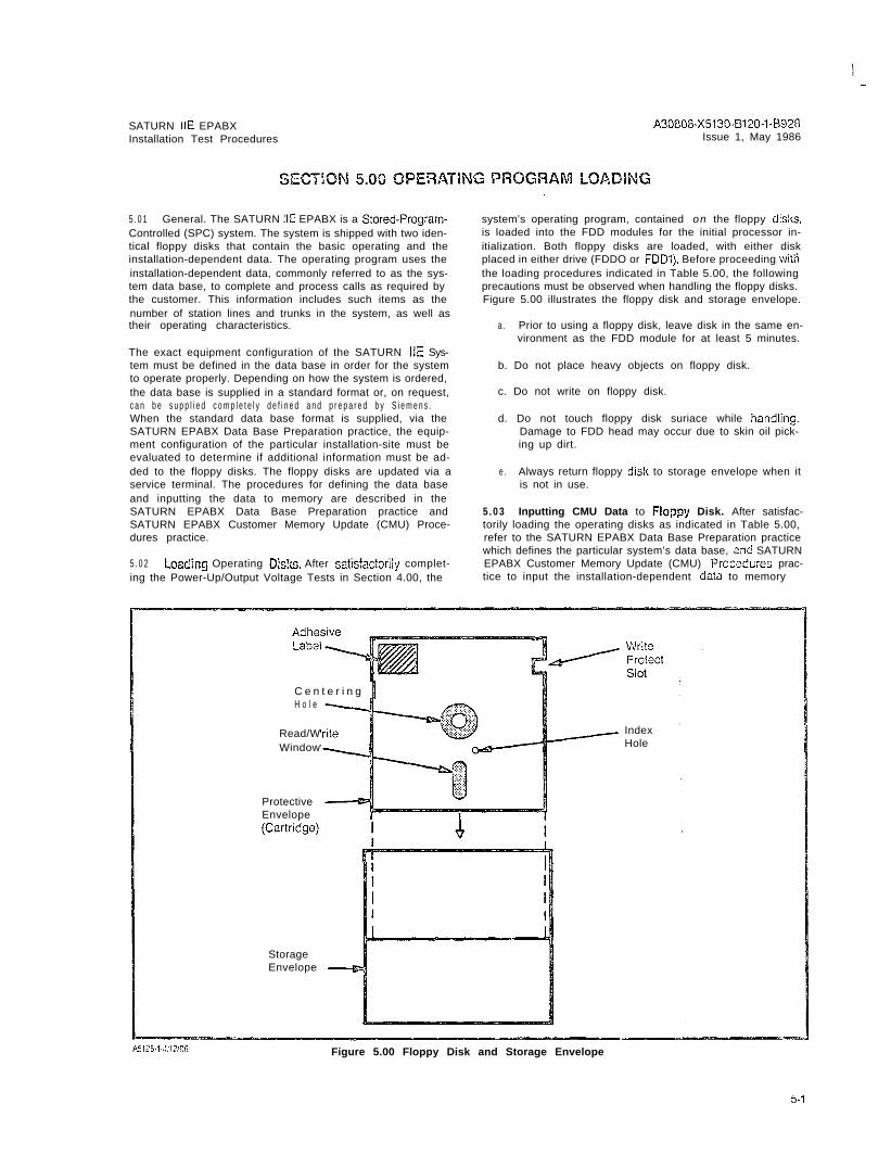
system’s operating program, contained on the floppy Uisks,is loaded into the FDD modules for the initial processor in-itialization. Both floppy disks are loaded, with either diskplaced in either drive (FDDO or FDDI). Before proceeding withthe loading procedures indicated in Table 5.00, the followingprecautions must be observed when handling the floppy disks.Figure 5.00 illustrates the floppy disk and storage envelope.
a . Prior to using a floppy disk, leave disk in the same en-vironment as the FDD module for at least 5 minutes.
b. Do not place heavy objects on floppy disk.
c. Do not write on floppy disk.
d. Do not touch floppy disk suriace while hand!ing.Damage to FDD head may occur due to skin oil pick-ing up dirt.
e . Always return floppy dislc to storage envelope when itis not in use.
5 . 0 3 Inputting CMU Data to F!oppy Disk. After satisfac-torily loading the operating disks as indicated in Table 5.00,refer to the SATURN EPABX Data Base Preparation practicewhich defines the particular system’s data base, and SATURNEPABX Customer Memory Update (CMU) Prccsdures prac-tice to input the installation-dependent da?a to memory
C e n t e r i n g 1H o l e
Read/WWindow
IndexHole
ProtectiveEnvelope
II
StorageEnvelope
Figure 5.00 Floppy Disk and Storage Envelope

SATURN IIE EPABX A3080&X5130-B120-l-8928Installation Test Procedures Issue 1, May 1986
WARNING
Hazardous voltages exist within the equipment cabinet. Be e&e&y careful whenperforming testir;g/~roobleshooting procedur-LJ with the equ&ment panel(s) removed.
Table 5.00 Loading Procedures for Operaling Disk
;TEP PROCEDURE VERIFICATION !F VERIFICATIONIS NOT OBTA!NED
1 On the PSU, shown in Figure 5.01,place the FAtLURE TRANSFERswitch in the AUTO position,
2 Insert a floppy disk into slot openingof each FDD until it stops (Figure 5.02).
NOTE:
Either system disk may be placed ineither FDD.
3 Close FDD latch to secure floppy diskin place.
4 Perform the following operations onthe CIOP PCB (Figure 5.03).
a) Connect service terminal to Set CIOP DlP switches (Figure 5.03)TTY connector on CIOP PCB for service terminal in use per Table(Figure 5.03). 5.01.
b) Depress the reset switch locat- The following ihree messages should If a failure occurs during initia!ization,ed under the CIOP llY con- appear on the service terminal: the LEDs flash a binary value to indi-nectar. Use pencil or other cate loading error as described in Ta-nonmetallic object to depress 1) THE SIB SIDE IS READY FOR ble 5.02.the switch. USE
Should any of the failures described2) READY TO START BOOT in Table 5.02 occur during processor
LOADER initialization, remove the floppy disks
3)“* BOOT LOADER COMPLETE”’from FDDs and insert the spare flop-py disks into the FDDs. If no failures
After the last message, the red cccur, the floppy disks previously re-STO-ST3 LEDs perform a cycling se- moved are defective. If the samequence and the green ACTV LED re- failure occurs, refer to ACTIONmains lit.
cOlumn in Table 5,02
When the loading process is com-plete, the red LEDs stop cycling andone LED remains lit for a few se-conds, then cycling starts again. Thegreen LED (ACTV) remains lit.
If no failures occur during processorinitialization, the four red LEDs displaya code indicating that processor in-itialization has been completed andthe processor is on-line. Concurrent-ly, the service terminal displays soft-ware version, date base version, patchlevel of disk software, site informationand the prompt ENTER PASSWORD.If it is desired to perform CMU proce-dures or clear the alarm stack, enterthe appropriate password. If theproper password is entered, a date-and-time prompt is displayed. If an in-correct password is entered, INVALIDPASSWORD ENTERED is displayed.
5 - 2
SATURN IIE EPABX A30808-X5130-0120-1-8928Installation Test Procedures lssuc 1, May 1936
Table 5.00 Loading Procedures for Operating Disk (Continued)
S T E P PROCEDURE VERlFlCATlON IF VERIFlCAT!ONIS NOT OBTAINED ’
5 If the operating disks that were load-ed did not contain a Siemens-.prepared data base, refer to SATURNEPABX Data Base Preparation prac-tice to define the particular systemdata base, and the SATURN EPABXCustomer Memory Update Proce-dures practice to input the installation-dependen t da ta to the sys temmemory.
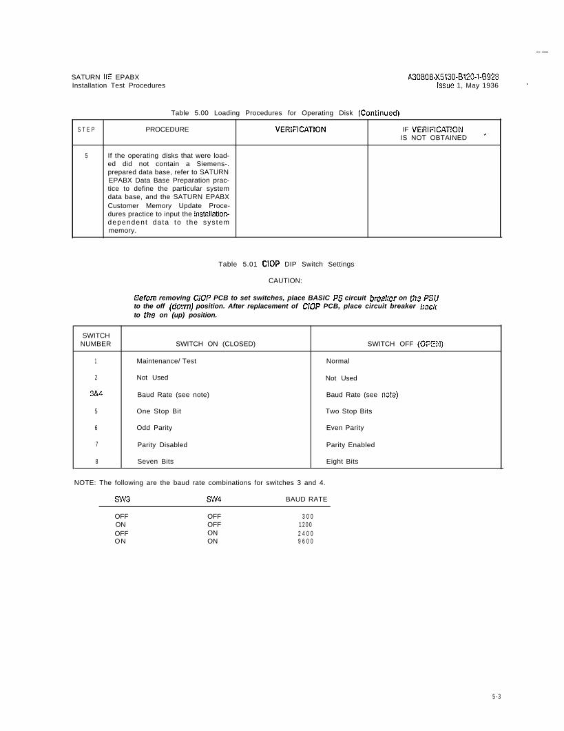
Table 5.01 CIOP DIP Switch Settings
CAUTION:
Before removing GOP PCB to set switches, place BASIC PS circuit brea!:er on lhe PSUto the off (c?own) position. After replacement of ClOP PCB, place circuit breaker backto the on (up) position.
SWITCHNUMBER SWITCH ON (CLOSED) SWITCH OFF (OPZX)
1 Maintenance/ Test Normal
2 Not Used Not Used
3&4 Baud Rate (see note) Baud Rate (see no?e)
5 One Stop Bit Two Stop Bits
6 Odd Parity Even Parity
7 Parity Disabled Parity Enabled
8 Seven Bits Eight Bits
NOTE: The following are the baud rate combinations for switches 3 and 4.
SW3 SW4 BAUD RATE
OFF OFF 3 0 0ON OFF 1 2 0 0OFF ON 2 4 0 0ON ON 9 6 0 0
5 - 3

I’
A30808-X5130-(3120-l-8928Issue 1, May 1986
T a b l e 5 . 0 2 LED Display Values for Loading Errors
HEXCCDE ERRCR DETECTED
0123456
:DEF89AI3
Start of self test not haltedMain processor errorEPROM checksum errorMEM slot 0 low 64k test error8k by 8 static RAM test errorIRAM memory test errorORAM memory test errorSIB side errorGlobal memory errorWatchdog iimer errorSIB serial loopback test errorSIB counter timing test errorStart boot process (self test done)Disk conirol ler errorDrive not ready errorCRC retry errcrs exceed 8
ST0LED
OFF
:zOFFOFFOFFOFFOFFONONONONONONONON
Notes:
I S T 1LED
OFFOFFOFFOFFONON
%ONONON
%FOFFOFFOFF
S T 2LED
OFFOFFONONOFFOFF
%OFFOFFON
%FOFFONON
S T 3LED
OFFONOFFONOFFONOFFONOFFONOFFONOFFONOFFON
ACTION
_._________-________N o t e 1N o t e 1Notes 1 and 3N o i e 1N o t e 1N o t e 1N o t e 1NOieS 1 and 3N o t e 1N o t e 1N o t e 1______-___--___-____--N o t e ‘ 1Note 2Note 2
1 . Upon failure, retry loading procedure. If failure persists, replace CIOP PC3.
2 . Upon failure, retry loading procedure using another set of floppy disks. If failure persists, chcc!i/replace disk drivesand then CIOP PCB, if necessary.
3 . If reload and CIOP PCB replacement (Noie 1) is not effective, replace memory PCBs starting from sloi 0 until failureis no longer present.
Figure 5.01 Po*wr Sys?em Unit (Front View)

I--
SATURN IIE EPABXInstallation Test Procedures
A30808-X5130-6120-1-8928Issue 1, May 1986
LATCHO P E N \
LATCH
CLoSED \
//
?
25
0
WRITEPROTECTNOTCH
FLOPPY
/ DiSi’c
Figure 5.02 Floppy Dish Loading Proceduics

I-
SATURN IIE EPABXInstallation Test Procedures
A30800-X5130-6120-l-8928Issue 1, May 1986
LED
LED(Red)
ST3LED
ACTW rLED
ConnectorService
Terminal
‘witch
Figure 5.03 CIOP Printed Circuit Coard
5-6 (6 pages)

SATURN IIE EPABX A30808-X5130-BlZO-l-8920Installation Test Procedures Issue 1. May 1986
6 . 0 1 General. After satisfactorily loading the cperating diskand inputting CMU data to system memory via a service ter-minal, the operational capability of the system must be veri-fied after the necessary MDF cross-connections areperformed. The SATURN IIE System software contains agroup of system and apparatus (ancillary equipment) diag-nostic test routines which are accessed via the maintenancephone. Resulting visual and/or audible responses from theseon-line diagnostic tests make it possible to verify correct oper-ation or detect and isolate system and apparatus malfunc-tions. If in doubt about a SATURN PCB or apparatusmal iunct ioning, craft personnel should refer to the SATURNIIE EPABX Mainionance and Troubleshooting praciice for fur-ther details. If a SATURN PCB or apparatus is proven to bedefective, craft personnel should proceed according to theinstructions contained in the MRA kit.
6.02 Connecticn of Maintenance Phcne and Modem.Figures 6.00 and 6.01 provide the details for the maintenancephone and modem initial MDF cross-connections. Figure 6.00also identifies the leads used when interfacing other main-tenance related equipment such as a power failure transfersubsystem and dry contact closures for remote minor andmajor alarm indications. Note that such equipment iscustomer-provided and craft personnel should follow themanufacturer’s instructions when installing them. To connectihe maintenance phone and modem, the initial MDF cross-connections aie as fol lows:
a . Maintenance Phone. At the MDF connecting block onwhich PSU cable J13 is terminated, cross-connect theT&R leads of pair number 1 (W/BL- BL/W) to the T&Rleads of the subscriber line circuit assigned for main-tenance purposes (refer to Figure 6.00 for details). Notethat this subscriber line circuit must be classmarkedwith the Maintenance Diagnostic Test (TESTDIAG) andApparatus Test (TSTAPP) features.
b . Modem. From the system T&R connecting block thatallocates system MDF cable J44 from the basic shelf,cross-connect the T&R of pair number 24 (V/BR- BR/V)to the T&R leads of the subscriber line circuit to be usedfor modem application (refer to Figure 6.01 for details).The subscriber line circuit to be used for modem ap-plication must be assigned to a class of service inwhich the Data Line Security (DATASEC) classmark hasbeen enabled.
A f t e r t h e a b o v e i n i t i a l M D F c r o s s - c o n n e c t i o n s h a v e b e e nperformed, the DTMF telephone set to be used as themaintenance phone can be connected to the modularjack designated MTCE PHONE on the PSU if equippedwith a standard modular plug, or connected at the MDFto the T&R leads of the associated subscriber line cir-cuit. Note that if a permanent maintenance phone is
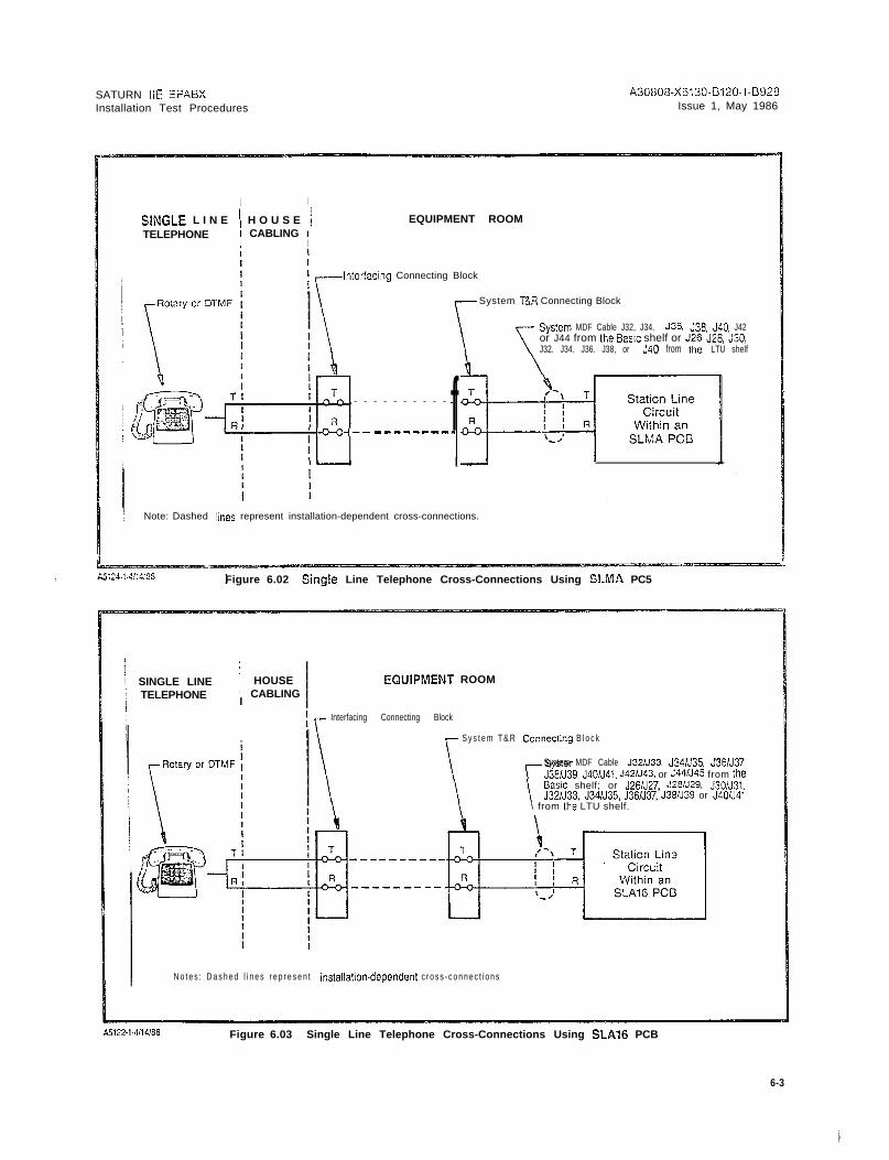
desrred in tho equipment, it may be installed nearthof r o n t o f t h e c a b i n e t , a n d c r o s s - c o n n e c t e d p e r F i g u r e 6 . 0 2 .
6 . 0 3 MDF Cross-Connecting Procedures. After the main- ’tenance phone and modem connections have been complet-ed, perform the necessary MDF cross-connections accordingto the equipment configuration plan. The following il lusira-tions are provided to assist craft personnel in the MDF crossconnections of peripheral interfacing devices:
a .
b .
C .
d .
e .
f .
9.
h .
i .
i
k.
I .
m
n .
0 .
Figures 6.02 and 6.03 - Cross-Connections for rotaryor pushbutton Single Line Telephone Instruments in-terfacing with SLMA-S and SLA16 PCBs, respectively.
Figure 6.04 - Cross-Connections for Siemens DigitalTelephone Interfacing with SLMD PCB.
Figure 6.05 - Cross-Connections for SATURN Atien-dant Console.
Figure 6.06 - Cross-Connections for Central Office(CO) and Direct Inward Dialing (DID) Trunks.
Figure 6.07 - Cross-Connections for Two-Wire (Type I)E&M Tie Trunks.
Figure 6.03 - Cross-Connections for Four-l”dirc (T]peI) E&M Tie Trunks.
Figure 6.09 - Cross-Ccnnections for T;:jo-Wire (T]pe I!)E&M Tie Trunks.
Figure 6.10 - Cross-Connections for Four Wire (TypeII) E&M Tie Trunks.
Figure 6.11 - Cross-Connections for Recorded An-nouncement Equipment (DID and Tie Trunk VacantNumber Intercept, and ACD Announcement Service).
Figure 6.12 - Cross-Connections for Coda CallingEquipment with or without Answerbaclc Capability.
Figure 6.13 -Cross-Connections for DTMF Dial Dicta-tion Equipment.
Figures 6.14 and 6.15 - Cross-Connections for Music-on-Hold Feature via a Music Source, interfacing witha TMBA4 and an SLMA/SLAlG PCB, respectively.
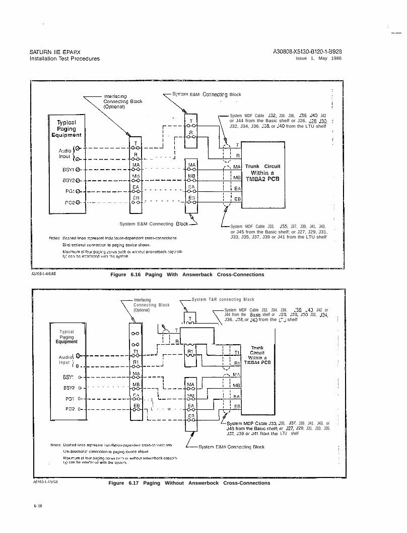
Figure 6.16 - Cross-Connections for Zoned PagingEquipment With Answerback Capability.
Figure 6.17 - Cross-Connections for Zoned PagingEquipment Without Answerback Capability.
Figure 6.18 - Cross-Connections for Zoned UniversalNight Answer (ZUNA or UNA) Signaling Equipment,
6-l

I.-
SATURN IIE EPABX A30808-X5130-B120-l-B928lnstallatlon Test Procedures Issue 1, May 1986
,-Syslein MDF Cable J13
Cross -connec t .to S L M A c i r c u i t d e s i g n a t e df o r t h e m a i n t e n a n c e t e l e p h o n e .
1 PXFER (No&h Ooen1J , I
P X F E R ( N o r m a l l y C l o s e d )
Cross-connect to failure transferrelay(s) subsystem (customer-p r o v i d e d ) .
\$$! > :tG TIP( M a j o r - N C )> R I N G ( M a j o r C o m m o n )
0 1 4D > FUBL TIP (Major-NO)
Dry contact closuresfor remoie miner andm a j o r a l a r m i n d i c a -tions (customer-p r o v i d e d ) .
Syslem Maiafcnancc Connecting Blsck
Figure 6.00 Mainienance Phone and Mainienance-Related Cross-Conneciions
System MDF Cable 144 from Basic Shelf
rSystem T&R Connecting Block
Cross-connect to SLMA circuit idesignated for Modem application. !
Note: The cross-connections shown are used for theRAUP PCB.
Figure G.01 Modem Cross-Connections
SATURN IIE EPABX A30808-X5130-B120-1-6928Installation Test Procedures Issue 1, May 1986
I I
SlNGLE L I N E ’ H O U S E /TELEPHONE ! CABLING I
I
EQUIPMENT ROOM
I
Inlerfacing Connecting Block
System T&R Connecting Block
Sys:em MDF Cable J32, J34. J36. C38. JSO, J42or J44 from the EZISIC shelf or J26, J28, J30,J32. J34. J36. J38, or J40 from tile LTU shelf
- - - - - - - - - - f-+(-Jo--- -________
[ ---I I I
I Note: Dashed lilies represent installation-dependent cross-connections.
Figure 6.02 Sing!e Line Telephone Cross-Connections Using SLMA PC5
SINGLE LINE I HOUSETELEPHONE i CABLING
I
EWIPMENT ROOM
\I
Interfacing Connecting Block
r S y s t e m T & R yecling B l o c k
System MDF Cable J321J33, J34/J35, J3EN37,J381J39, J401J41, J42/J43. or J441J45 from the
\ \ \Basic shelf; or J26N27, J28N29, J3O/J31,J32/J33, J34/J35, J36/J37, J38/J39 or J4O/J41
\ from Lhe LTU shelf.
N o t e s : D a s h e d l i n e s r e p r e s e n t installation-dependent c r o s s - c o n n e c t i o n s
Figure 6.03 Single Line Telephone Cross-Connections Using SLA16 PCB
6-3
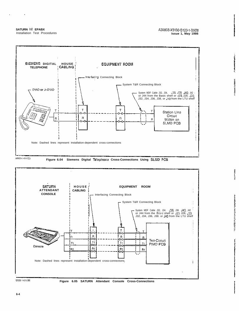
SATURN IIE EPABXInstallation Test Procedures
A30808-X5130-B120-l-8928Issue 1, May 1986
I II
SIEMENS DIGITAL : HOUSE ’ EQUlPMENT FiOOMTELEPHONE ICABLING! .
II II I1
Interfacing Connecting BlockI\ .
DYAD or Jr-DYAD
Figure 6.04 Siemens Digital Te!cphone Cross-Connections Using SLMD PC9
System T&R Connecting Block 1System MDF Cable J32, J34, J36. J38, J40. J42 :or J44 from the Basic shelf or J26, J28, J30, jJ32, J34, J36, J38, or J40 from the LTU shelf
Note: Dashed lines represent installation-dependent cross-connections
SAbRNATTENDANT
CONSOLE
H O U S E i EQUIPMENT ROOMICABLING
Interfacing Connecting Block
System T&R Connecting Block
System MDF Cable J32, J34. J36. J38. J40. J42 ior J44 from the Basic shelf or J25 J28, J30, ;J32, J34, J36, J38. or J40 from the LTU shelf j
Note: Dashed lines represent installation-dependent cross-connections.I
Figure 6.05 SATURN Attendant Console Cross-Connections
6-4

SATURN IIE EPABX A30808-X5130-B120-1-6928Installation Test Procedures Issue 1, May 1986
CENTRALOFFICE
co QP C3DTrunkCircuit
; T R U N K ; CUSTOMER PREMISESI FAClLlTY :I
i
Local Telephone CompanyII Interfacing Connecting Bloc!c
System MDF Cable J32. J34, J35, J38, J40. J42or J44 from the Basic shelf or J26, J28. J30, J32,J34. J36, J38. or J40 from the LTU shelf
L System T&R Connecting Dock
NO!% Dashed lines represcnl ins!allalion-dependenr cross-CCnnEcfions
Figure G.06 63 and DID Trunk Cross-Connections
DISTANTOFFICE
OR SlGNALINGEQUIPMENT
T R U N K i CUSTOMER PREMlSESFACILITV 1
Interfacing Connecting Block
System T&R Connecting Block
ystem MDF Cable J32. J34. J36. J33. J40. J42 or44 from the Dasic shelf or J26. J28. J30. J32, J34,36. J38, or J40 from the LTU shelf
I
i
J39, J41. J43, or‘3. J31, J33. 335.i f
System E&M Connecting Block
Figure 6.07 Two-Wire (Type I) E&M Trunk Cross-Connections
6-5

I-
SATURN IIE EPABXInstallation Test Procedures
A30808-X5130.B120-l-8928Issue 1, May 1986
DISTANT I -l-RUN!< IOFFICE ; FACILITY 1
OR S I G N A L I N G ;EQUIPMENT
I
IIII
CUSTOMER PREMISES
Interfacing Connecilng Block
System T&R Connecting Bloc!c
System MDF Cable J32. J34. J36, J38. J40, J42or J44 from the Basic shelf or J26. J28, J30, J32,J34, J36, J38, or J40 from the LTU shelf
Y L System MDF Cable J33, J35, J37, J39, J41, J43,or J45 from the Basic sheif; or J27. J29, J31, J33,J35. J37, J39 or J41 from the LTU she!f
L System E&M Connecting 6lock
A5135-1-4/W3!3 Figure 6.06 Four-Wire (Type ;) E&M Trunk Cross-Connections
DISTANT I T R U N K fOFFICE t FACILITY :
OFI SIGNALING ( IEQUIPIMENT
I iI t
CUSTOMER PREMISES
Interfacing Connecting Block
~System T&R Connecting B!ock
i
I
a
System MDF Cable J32, J34. J36, J38, J40, J42or J44 from the Basic shelf: or J26. J28. J30, J32,J34, J36. J38, or J40 from the LTU shelf
LoS y s t e m M D F C a b l e J 3 3 , J 3 5 ,or J45 from the Baw shelf; orJ35, J37, J39 or J41 from the
J37.J27,
L T U
J39. J41, J43,J29, J31, J33,shelf
IL-.System E&M. Connecting Elock
Figure 6.09 Two-Wire (Type II) E&M Trunk Cross-Connections
6-6

I--
SATURN IIE EPABX A3080i3-X5130-B120-1-69.28Installation Test Procedures Issue 1, May 1986
DISTANTO F F I C E
OR SIGNALINGEQUIPMENT
I Four-Wire
IType II E&M
Trunkor
SignalingCircuit
-R-
I!Rl
E-
S C-
M-
SE-
TRUNK ;FACiLlTY f
CUSTOMER PfiErvwzs
In:er:ach~g Conneclmg Block
System T&R Connecilng Block
r - - - - - -
I
634. J3S. J30. J40. J42 or J44‘J28.J~O.J32,~34.J3S.J33.
35, J37, J39. J41. JS3. or J457. J29, J31. J33,,‘35, J37, J29
System E&M Connecting Block
E!o!e: Dashed lines represent ins:al!ation-dependent crcc;-connections.
Figure 6.10 Four-Wiro (Type ii) E&M Tiunlc Cross-ConnecZions
Cable J32. J34, J36. J33. J40, J42or J44 from the Basic shelf or J26. J28, J30, J32,J34. J36. J38. or J40 from the LTU shelf
A u d i o Goutput 81
SMl @ -------
S M 2 @- -------
SZl a- ___-----
sz2 a- ------
u
TypicalAnnouncement
Equipment
- S y s t e m M D F C a b l e J 3 3 . J 3 5 , J37, J 3 9 , J4!, J 4 3 ,or J45 from the Basic shelf; or J27, J29. J31. J33.
Some ann~uncemenl machines send both Start Message (SM) and Make J 3 5 , J 3 7 , J 3 9 o r J41 f r o m t h e L T U s h e l fBusy (MB) signals over same par (EAIEB). P
S y s t e m E & M C o n n e c t i n g B l o c k
A5126-l-4,8/86 Figure 6.11 Recorded Announcement (DID and Tie Trunk Vacant Number intercept, andAC3 Announcement Service) Cross-Connections
6 - 7

SATURN IIE EPABXInstallation Test Procedures
A30808-X5130-B120-l-8928Issue 1, May 198G
Connecting Block
System T&R Connecting Block
No:es: Dashed lines represent installation-dependent cross-connectrons
Ei-drrecticnal connection to code calling device for both calling and an-swerback channels shown.
Maximum of one code calling equipment (with or without answerbaclc capa-bility) can be interfaced with the system.
When maintenance procedures are to be performed on code callrng equip-ment, associated trunk circuit must first be taken out-of-service. Failureto observe this will cause users accessing code calling to receive unan-swered ringback tone instead of busy tone.
System MDF Cable J32, J34,J36, J38, J4.0, J42 or J44 from theBasic shelf or J25, J28, J30, J32,J34, J36, J38, or J40 from the LTUsheif
~Il”-i-4:oIES Figure 6.12 Code Cailing (With or Without Answcrba~h) Cross-Comedons
s t e m MDF Cable J32, J34, J36, J38,, J42 or J44 from the Basic shelf or, J28, J30, J32, J34, J36, J38, or J40
m the LTU shelf
Notes: Dashed lines represent installation-dependent cross-connections,
Bi-directional connecction to DTMF dictation equipment shown.
Maximum of four DTMF dial dictation circuits can be interfaced with thesys tem.
When maintenance procedures are to be performed to a dial dictation equip-ment, the associated SLMA crrcuit must first be taken out-of-servrce. Fatlureto observe this will cause users accessing the dial dictation equipment tohunt to an out-of-service device and receive unanswered ringback toneinstead of being routed to an in-service device or receiving busy tone.
Figure 6.13 Dial Dic?ation (DTMF) Cross-Connections

SATURN IIE EPABX A30808-X5130-B120-l-8928Installation Test Procedures Issue 1, May 1988
I n t e r f a c i n gConnectmg Block
System T&R Connecttng 61ocl( I
(Op!lonal) System MDF Cable J32. J34. J36. .Jm. J40. J42 or J44 r
hA---- from the Basic shelf or J26. J28, J33, J32, J34, J3G. J38. j
or J40 from the LTU shelf I
Figure 6.14 Music-cn-Wc!d Cross-Connections Using TMBA4 PC0
System E&M Connecting Block
L System MDF Cable J33: J35, J37, J33. J41, J43. or J45from the @asic shelf; or J27, J29, J31, J33, J35, J37, J39or J41 from the LTU shelf
Notes: Dashed lines represent installation-dependent cross-connections. Broadcast type connection from music sources h o w n . Two k i n d s o f m u s i c s o u r c e c a n b e c r o s s - c o n n e c t e d , c o n -tinuous type and demand type. For continuous mustc, the E&Mleads are not used; and for demand music, the E&M leads are
EQUIPMENT ROOM
T Interfacing Connecting Sloc!c
System T&R Connecting Block
Figure 6.15 Music-on-Hold Cross-Connections Using SLMAiSLAl6 PCB
Music Source
System MDF Cable J32, J34. J36, J36, JSO, J42or J44 from the Basic shelf or J26, J26, J30, J32,J34, J36, J38, or J40 from the LTU shelf
T \a- - - - - ----- - ,--\ T Station LineI 1
CircuitWithin an
SLMAlSLAlG PCB
Notes: Dashed lines represent installation-dependent cross-c o n n e c t t o n s .
System MDF Cable connections are shown for anSLMA PCB. For SLA16 connections, refer to Ftgure6.03.
Only continuous type music sources may be cross-connected.
6-9
A30808-X5130-0120-1-8928issue 1, May 1986
System E&M Connecting Block
System MDF Cable J3.2, J34. J36, J36. J40, J42or J44 from the Basic shelf or J26, J26, J30.J32, J34, J36. J36, or JSO from the LTU shelf
_ _ - - - -
- - - - - - -
-----mm
- - - - - - - -
- - - - - - -
Trunk Circuit
System E&M Connecting Block\ L System MDF Cable J33. J35. J37, J39, J41, J43,or J45 from the Basic shelf; or J27, J29, J31,J33, J35, J37, J39 or J41 from the LTU shelf
A5!59-,-4,9:66 Figure 6.16 Paging With Answerback Cross-Connections
T y p i c a lPaging
Equipment
Audio 8-I n p u t
i 0
BSYl 0
BSY2 0
PGl 0
PG2 0
InterfacingC o n n e c t i n g B l o c k(Optional)
[IO’ used’pJk/--j.,,-I r---m7 -
i-w---1
- - - - - - - - -
S y s t e m T & R c o n n e c t i n g B l o c k
System MDF Cable J32. J34. J36. J36. J40. J42 orJ44 from the Basic shelf or JZG. J28. J30. J32, J34,
/I
J36. J38. or J40 from the LTU shelf
- - 1 L----II
7 L - - w - -IIL---s--
J35, J37, J39. J41. J43, oror J27, J29. J31. J33. J35.LTU shelf
Figure 6.17 Paging Without Answerbock Cross-Connections
6-10

SATURN IIE EPABX A30808-X5130-6120-1-8928Installation Test Procedures Issue 1, May 1986
System T+R Connecting Block I
Interfacing
\Connec t ing B lock
System MDF Cable J32, J34, J36, J38,J40, J42 or J44 from the Basic shelf or
(Optional) J26, J28. J30, J32, J34, J36, J38 or J40 iUNA Signaling Device from the LTU shelf
- - - - - a - - - - - - -
With an- - - - - -SLMAISLAlG PC13
Notes: Dashed lines represent installation-dependent cross-connections.
System MDF Cable connections are shown for an SLMA PCS. For SLA16connections, refer to Figure 6.03.
An AC signaling device operated by 20Hz ringing voltage must be con-nected to an SLMA circuit used for UNA. Each UNA circuit will drive upto four equivalent ringer loads. For installations requiring -48Vdc or a drycontact closure for UNA. appropriate external equipment must be used.
The system will support up to four UNA signaling zones (i.e.; ZUNA); oneSLMA circuit is assigned per zone.
Figure 6.18 Un iversa l N igh t Answer (UNA) Cross -Connec t ions
6-11

SATURN IIE EPAEXInstallation Test Procedures
I-
6 . 0 4 System Diagnostic Tests. After the necessary MDFcross-connections have been completed, the on-line diagnos-tic icsts and procedures are performed to verify the opera-tronal capability of the system. Note that the subsequenton-line diagnostic tests and procedures are presented in thesequence in which they should be performed under normalinsial lat ion conditions. It is the responsibility of craft pers,on-nel to determine the sequence in which such tests and proce-dures should be performed when unusual installationconditions exist. Unless otherwise indicated, these tests canbe performed with SDTs and/or DTMF SLTs.
a . Tone Generator Test. This system diagnostic test rou-tine verifies that each tone provided by the SMXTGPCS is generated properly. In addition, the test alsochecks the connection path(s) through the MemoryTime Switch (MTS). Refer to Table 6.00 for the neces-sary procedures to perform the tone generator test.
b . DTMF Receiver Test. This system diagnostic test rou-tine verifies that a DTMF receiver circuit in a aarticu-lar DTMF PCB is operating properly. The test alsochecks the connection path(s) through the MTS. Referto Table 6.02 for the necessary procedures to performthe applicable DTMF receiver circuit test(s). This testr e q u i r e s a T y p e 2 5 0 0 D T M F P u s h b u t t o n T e l e p h o n e S e t .
c . Station Line Test. This apparatus diagnostic test rou-tine verifies that the supervisory and transmissioncapabilities between an SLMA, SLA16 or SLMD cir-cuit and asscciated staiion or Siemens Digital Tele-phone instrument are operating properly. This test isperformedfrom the station instrument under test andapplies to both single line telephones (rotary or push-button) and Siemens Digital Telephones. Refer to Ta-ble 6.03 for the necessary procedures to perform theapplicable station line test(s).
d . DTMF Pad Test. This apparatus diagnostic test routineverifies that the DTMF keypad performance, includingthe transmission capabilities, of any DTMF pushbutton-type station instrument is operating properly. The testis performed from the station instrument under test andonly applies to single line telephones equipped witha D T M F k e y p a d . N o t e t h a t a S i e m e n s D i g i t a l T e l e p h o n ecannot be used for this test since data, not tones, aretransmitted from the SDTs pushbutton keypad. Referto Table 6.04 for the necessary procedures to performthe applicable DTMF pad test(s).
e . Console Test. This apparatus diagnostic test routineverifies that the data and speech highways to and froman attendant console are operating properly. The testalso verifies that the console LED indicators, alphanu-meric display unit and audible alerting device are oper-
f .
9
h .
i .
j.
A30808-X5130-5120s1-8928Issue 1. May 1986
ating properly. The test is performed from the consoleunder test. Refer to Table 6.05 for the necessary proce-dures to perform the applicable console tes:s.
S i e m e n s D i g i t a l T e l e p h o n e B u t t o n T e s t s . T h e s e a p p a r a -tus diagnostic test routines verify that the signalinghighways to and from Siemens DYAD and JR-DYAD tel-ephones are operating properly. In addition, the testsalso verifv that the LEDs and the audible alert inndevices of the telephones are operating properly. Thetests are performed using the DYAD and JR-DYAD tel-ephones. Refer to Tables 6.07 and 6.08 for the neces-sary procedures to perform the applicable Siemensdigital telephone button tests.
Siemens Digital Telephone Display Test. This appara-tus diagnostic test rouiine verifies that the signalinghighways to and from the Siemens DYAD telephonesare operating properly. In addition, the tests also veri-fy that the alphanumeric display unit and the audiblealerting devices are operating prcperly. The tests areperformed using the DYAD telephones under test.Refer to Table 6.09 for the necessary procsdurcs to per-form the Siemens digital ie!ephone display tests.
Trunk Test. This system diagnostic test verifies that thesupervisory and transmission capabilities of an outgo-ing (or outgoing portion of a two-way) trunk are oper-ating properly. In addiiion, the test also verifies theconnec?ion p a t h ( s ) t h r o u g h t h e M T S . R e f e r t o Tab!o 6 . 1 1for the necessary procedures to perform the eppl ica-ble trunk tests.
Placing Circuit(s) In-Service. This system procedure al-lows craft personnel to place an assigned circuit inservice from an out-of-service state. This procedureworks in parallel with the CMU procedure that changesa circuit’s state. Refer to Table 6.12 for the necessaryprocedures to perform the applicable in-service place-ment of circuits.
Placing Circuit(s) Out-of-Service. This system proce-dure allows craft personnel to place an assigned cir-cuit out-of service from an in-service state. Thisprocedure works in parallel with the CMU procedurethat changes a circuit’s state. Fiefer to Table 6.13 forthe necessary procedures to perform the applicableout-of-service placement of circuits.
WARNING
Hazardous voltages exist Mhin the equipmcnr cebkc?.B e e x t r e m e l y c a r e f u l w h e n p e r f o r m i n g t e s t -i ng / t roub leshoo t i ng p rocedu res w i ih Ehe equ ipmentpanel(s) removed.
G - l ?
SATURN IIE E?ABX A30808-X5130-8120-l-8928Installation Test Procedures issue 1, May 1986
TEP
1 P lace ma in tenance t es t phoneoff-hook.
Dial tone returned.
2 D i a l t h e Diagncstic T e s t A c c e s s C o d e . Recall dial tone returned.
3
4 A
Dial 1 for tone generator test. N o n e .
D i a l 0 0 i f a l l t o n e s a r e t o b e t e s t e d a n dverify that all tones returned are un-dis!orted.
A l l t o n e s a r e r e t u r n e d i n t h e s e q u e n c eshown in Table 6.01 for two secondseach: test repeats until the main-tenance test phone is placed on-hookor hook flashed.
4B D i a l t h e i n d i v i d u a l t e s t n u m b e r s h o w n Chosen tone returned until main- If chcsen tono is returned dictoricd.in Table 6.01 if a particular tone is to tenance test phone is placed on-hco!c retry test two moie times. If distortionbe tested. or hook-flashed. continues, replace the SMXTG PCB
5 A If additional tE?SiS or procedures areto be performed, hook-flash the main-tenance test phone and dial the nextcode (Diagnostic Test Access Code isnot redialed).
Recall dial tone is returned.
56 I f n o a d d i t i o n a l t e s t s o r p r o c e d u r e s a r eto be performed, placa the main-tenance test phone on-hook.
Nono.
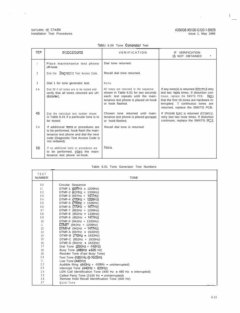
iab:a 6.00 Tone Generator Test
PCDCECURE V E R I F I C A T I O N
T E S TNUMBER
0 00 10 20 30 40 50 60 70 80 91 01 11 21 31 41 51 61 71 81 92 02 12 22 32 42 52 62 7
IF VERIFICATIONIS NOT OBTAINED s
If any tone(s) is returned distortad retrytest two mere times. If distortion con-t i n u e s , r e p l a c e t h e S M X T G P C B . Nctothat the first 16 tones are hardware in-terrupted. if continuous tones arereturned, replace the SMXTG PCB.
Table 6.01 Tone Generator Test Numbers
TONE
Circular SequenceDTMF-1 (697Hz + 1209Hz)DTMF-2 (6Q7Hz + 1336Hz)DTMF-3 (697Hz + 1477Hz)DTMF-4 (77OHz + 1209Hz)DTMF-5 (77OHz + 1336Hz)DTMF-6 (77OHz + 14i7Hz)DTMF-7 (852Hz + 1209Hz)DTMF-8 (852Hz + 1336Hz)DTMF-9 (852Hz + 1477H.z)DTMF-0 (941Hz + 133SHz)DTMF-’ (941Hz + 1209Hz)DTMF-# (941Hz + 14i7Hz)DTMF-A (697Hz + 1633Hz)DTMF-B (770Hz + 1633Hz)DTMF-C (852Hz + 1633Hz)DTMF-D (941Hz -I- 1633Hz)Dial Tone (35OHz + 440Hz)Busy Tone (480Hz +620 Hz)Reorder Tone (Fast Busy Tone)Test Tone (1004Hz @-16dEim)Low Tone (440Hz)Audible Ring (440Hz + 480Hz - uninterrupted)Intercept Tone (440Hz + 620Hz)LDN Call Identification Tone (400 Hz + 480 Hz - interrupted)Called Party Tone (2100 Hz - uninterrupted)Remote Hold Recall Identification Tone (400 Hz)Q u i e t T o n e --_
G - 1 3
I
SATURN IIE EPABX A30808-X5130-B120-l-8928Installation Test Procedures Issue 1, May 1986
S T E P PROCECURE VEFHFICATION
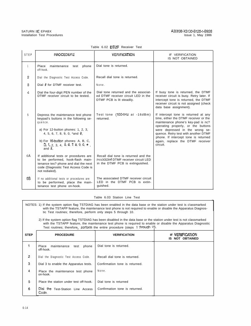
1
5
6A
68
Table 6.02 DTMF Receiver Test
Place maintenance test phoneo f f - h o o k .
D i a l t h e D i a g n o s t i c T e s t A c c e s s C o d e .
Dial # for DTMF receiver test.
Dial the four-digit PEN number of theDTMF receiver circuit to be tested.
Depress the maintenance test phonekeypad’s buttons in the following se-q u e n c e .
Tes t tone (1004Hz a t - 16dBm)returned.
a) For 12-button phones: 1, 2, 3,4, 5, 6, 7, 8, 9, 0, *and #.
b) For 16-button phones: A, B, C,D, 1 , 2, 3, 4, 5, 6, 7 , 8, 9, 0, * ,and #.
If additional tests or procedures areto be performed, hook-flash main-tenance tes? phone and dial the nextcode (Diagnostic Test Access Code isnot redialed).
Recall dial tone is returned and theassociaied DTMF receiver circuit LEDin the DTMF PCB is extinguished.
I f n o a d d i t i o n a l t e s t s o r p r o c e d u r e s a r e The associated DTMF receiver circuitto be performed, place the main- LED in the DTMF PCB is extin-tenance test phone on-hook. guished.
Dial tone is returned.
Recall dial tone is returned.
N o n e .
Dial tone returned and the associat-ed DTMF receiver circuit LED in theDTMF PCB is lit steadily.
IF VERIFICATIONIS NOT OBTAINED
If busy tone is returned, the DTMFreceiver circuit is busy. Retry later. Ifintercept tone is returned, the DTMFreceiver circuit is not assigned (checkdata base assignment).
If intercept tone is returned at anytime, either the DTMF receiver or themaintenance phone’s key-pad is nc?operating properly, or the buttonswere depressed in the wrong se-quence. Retry test with another DTMFphone. If intercept tone is returnedagain, replace the DTMF receivercircuit.
Table 6.03 Station Line Test
NOTES: 1) If the system option flag TSTDIAG has been enabled in the data base or the station under test is c!assmarkedwith the TSTAPP feature, the maintenance test phone is not required to enable or disable the Apparatus Diagnos-tic Test routines; therefore, perform only steps 5 through 10.
2) If the system option flag TSTDIAG has been disabled in the data base or the station under test is not classmarkedwith the TSTAPP feature, the maintenance test phone is required to enable or disable the Apparatus DiagnosticTest routines; therefore, oerform the entire procedure (steps 1 throuqh 11).
STEP
.
PROCEDURE VERIFICATION
Place maintenance test phoneoff-hook.
Dial tone is returned.
D i a l t h e D i a g n o s t i c T e s t A c c e s s C o d e .
Dial 3 to enable the Apparatus tests.
Place the maintenance test phoneon-hook.
Recall dial tone is returned.
Confirmation tone is returned.
N o n e .
Place the station under test off-hook. Dial tone is returned
;:;ethe Test-Station Line Access Confirmation tone is returned.
IF VERIFKATIONIS NOT OBTAINED
1
6 - 1 4

SATURN IIE EPABXInstallation Test Procedures
A30808-X5130-B120-l-8928Issue 1, May 1986 .
Tab!c A.03 Station Line Test fCnntinc)edl
,S T E P PROCEDURE
\-----------I
S T E P FROCEDUZZ VERIFICATTION IF VER!FiCATIONIS NOT OBTAINED ’
7 Place station under test on-hook. Ringing returned. If ringing is not heard, switch the sta-tion instrument to determine if it isdefective. If ringing is still not heard,replace the associated subscriber lineP C B .
8 Pick up handset to answer test ta i l .
9 Verify that the test tone level is cor- Test tone (1004Hz @ -lGdBm) is If the returned test tone level is weak,rect by using a TMS. returned. swap the instrument to determine if it
is defective If the test tone level in-creases considerably, replace the s:a-tion instrument. If test tone levelremains weak, replace the associat-ed subscriber line PCB (SLMA,
1 0 Place station under test on-hoo!(.SLA16 or SLMD).
N o n e .
1 1 I f n o a d d i t i o n a l T e s t r o u t i n e s a r e t o b eperformed, proceed as follows:
Place maintenance test phone Dial tone is returned.off-boo!<.
Dial the Diagnostic Test Access Code Recall dial done is returned,
Dial 2 to disable test routine. N o n e .
Place maintenance phone on-hook. N o n e .
Tab!e 6.04 DTMF Fad Test
NOTES: 1) If the system option flag TSTDIAG has been enabled in the data base or the station under test is classmaikedwith the TSTAPP feature, the maintenance test phone is not required to enable or disable the Apparatus Testroutines; therefore, perform only sieps 5 through 8.
2) If the system option flag TSTDIAG has been disabled in the data base or the station under test is not classmarkedwith the TSTAPP feature, the maintenance test phone is required to enable or disable the Apparatus Test rou-tines; therefore, perform the entire procedure (steps 1 through 9).
VERIFICATION IF VERIFICATIONIS NOT OBTAINED
1 Place maintenance test phone Dial tone is returned.off-hook.
2 D i a l t h e D i a g n o s t i c T e s t A c c e s s C o d e . Recall dial tone is returned.
3 Dial 3 to enable the tests. Confirmation tone returned.
4 P lace ma in tenance tes t phone None .on-hook.
5 Place DTMF station under test Dial tone returned.off-hook.
6 D i a l t h e T e s t D T M F P a d A c c e s s C o d e . Recall dial tone is returned.
6-15

SATURN IIE EPABX A30808-X5130-B120-l-B928instaliation Test Procedures Issue 1, May 1986
Wbtc 6.04 DTMF Pad Test
S T E P PWO@EDWE VERIFICATION IF VERIFICATIGNIS NOT OBTAINED
7 Depress the DTMF keypad buttons in Recall dial tone ceases. After all the If busy tone is returned at any time,the following sequence: DTMFjteypad buttons are depressed e i t h e r t h e D T M F k e y p a d b u t t o n s w e r e
in the sequence indicated, test tone depressed in the wrong sequencetheFor 12-button phones: 1, 2, 3, 4, 5, 6, (1004Hz @ -16dBm) is returned for D T M F k e y p a d o f t h e s t a t i o n u n d e r t e s t7 , 8, 9, 0, 4 and #. one minute. is defective or the subscriber line cir-
cuit is defective.For 16-button phones: A, B, C, D, 1,2, 3, 4, 5, 6, 7, 8, 9, 0, * and #. T o l o c a t e f a i l u r e , r e t r y t e s t t o v e r i f y t h a t
the keypad but tons were no tdepressed out o f sequence. I fproblem persists, swap the station in-s t r u m e n t t o d e t e r m i n e ii i t i s d e f e c t i v e .If problem remains, replace the rp-propriate subscriber line PCB.
8 F;Q;he level of test tone by using If the measured test tone is correctbut is weak, replace the station set.If the measured tone is low, rep!acethe subscriber line PCB SLMA orSLA16).
9 Place DTMF station under test on- N o n e .hook to terminate test.
1 0 If no additional apparatus tests are tobe performed, proceed as foilows:
Place maintenance test phone Dial tone is returned.off-hoo!(.
D i a l t h e D i a g n o s t i c T e s t A c c e s s C o d e . Recall dial tone is returned.
Dial 2 to disable the Apparatus Tests. N o n e .
P lace ma in tenance tes t phone None .on-hook.
Table 6.05 Console Test
N O T E S : 1 ) If the system option flag TSTDIAG has been enabled in the data base, the maintenance test phone is not requiredto enable and disable the Apparatus Test routines; therefore, perform only steps 5 through 9.
2) If the system option flag TSTDIAG has been disabted in the data base, the maintenance test phone is requiredto enable and disable the Apparatus Test routines; therefore, perform the entire procedure (steps 1 through 10).
S T E P PROCEDURE VERIFICATION IF VERIFICATIONIS NO-i- OBTAINED
1 Place maintenance test phone Dial tone is returned.off-hook.
2 D i a l t h e D i a g n o s t i c T e s t A c c e s s C o d e . Recall dial tone is returned.
3 Dial 3 to enable the Apparatus Tests. Confirmation tone is returned.
4 P lace ma in tenance tes t phone None .on-hook.
5 At the Console under test dial the At- Recall dial tone is returned. Also the If reorder tone is returned, the Atten-tendant Console Test access code access code is displayed momentar- dant Console Test routine is in use,when the console is in an idle state. ily, then the display changes to CON- retry later.
SOLE TEST and all button LEDs areextinguished.
6 - 1 6

SATURN IIE EPABX A30808-X5130-B120-l-8928Installation Test Procedures Issue 1, May 1986
Table 6.05 Console Test (Continued)
:TE? PRCCEDURE VERIFICATIDN lF VERlFlCATlONIS NOT OBTAINED +
6 Depress the console’s keypad buttons All digits dialed are displayed (ac- I f p r o p e r v e r i f i c a t i o n i s n o t o b t a i n e d o r
in the following sequence: 1, 2, 3, 4, c u m u l a t e ) . busy tone is returned at any time, the5, 6, 7, 8, 9, 0, * and #. keypad buttons or console buttons
were depressed out of sequence, the7 Depress the console’s feature buttons Each bu t ton LED l i gh ts when console is defective, or P IMD circuit
i n t h e s e q u e n c e s h o w n i n F i g u r e 6 . 1 9 . ’ depressed and extinguishes when the i s d e f e c t i v e . T o i s o l a t e t h e f a i l u r e , r e t r ynext key is depressed. test to verify that the buttons were not
depressed out of sequence.a After the last button in the sequence G r o u p s o f e i g h t o f e a c h o f t h e display- I f p r o p e r v e r i f i c a i i o n i s n o t o b t a i n e d o r
is depressed, depress any console able characters are scrolled in the se- busy tone is returned again, replaceb u t t o n t o i n i t i a t e t h e d i s p l a y t e s t . T h e quence s h o w n i n T a b l e 6 . 0 6 . Ai-ier t h e assoc ia ted PIMD PCB to ver i f yd isp lay can be suspended by last character is displayed (under whether the PIMD circuit or the con-depressing any key on the console score character), the display unit is sole is defective. If proper verificaiionand resumed in the same manner. cleared and the following LEDs is obtained, replace the associa?ed
momentarily light then extinguish in PIMD P C B . I f p r o p e r v e r i f i c a t i o n i s n o tthe following sequence: obiained or busy tone is returned
again, replace the console.a) TRUNK GROUP STATUS 1 -
b) %“RCEc) DESTINATIONd) ALERTe) CW9 MAJ ALMg) MIN ALM
After the above indications are com-pleted the fo!lowing indications occur:
Ringbeck tone is returned.
All LEDs on the display assemblyf l a s h . .
.
After the above indications are com-p l e t e d t h e f o l l o w i n g i n d i c a t i o n s o c c u r :
Ringback tone is returned.
All LEDs on the display assemblyflash.
T h e a u d i b l e a l e r t i n g d e v i c e s o u n d s a ti n t e r v a l s .
REMOVE HANDSET is displayed.
9 Remove and reinsert handset assem- INSERT HANDSET is displayed whilebly to terminate test, or wait 30 se- handset is removed. After handset isconds for test timeout. reinserted, console returns to normal
o p e r a t i o n .
1 0 If no additional apparatus tests are tobe performed, proceed as follows:
Place maintenance test phone Dial tone is returned.off-hook.
D i a l t h e D i a g n o s t i c T e s t A c c e s s C o d e . Recall dial tone is returned.
Dial 2 to disable the Apparatus Tests. N o n e .
P lace ma in tenance tes t phone None .on-hook.
6 - 1 7
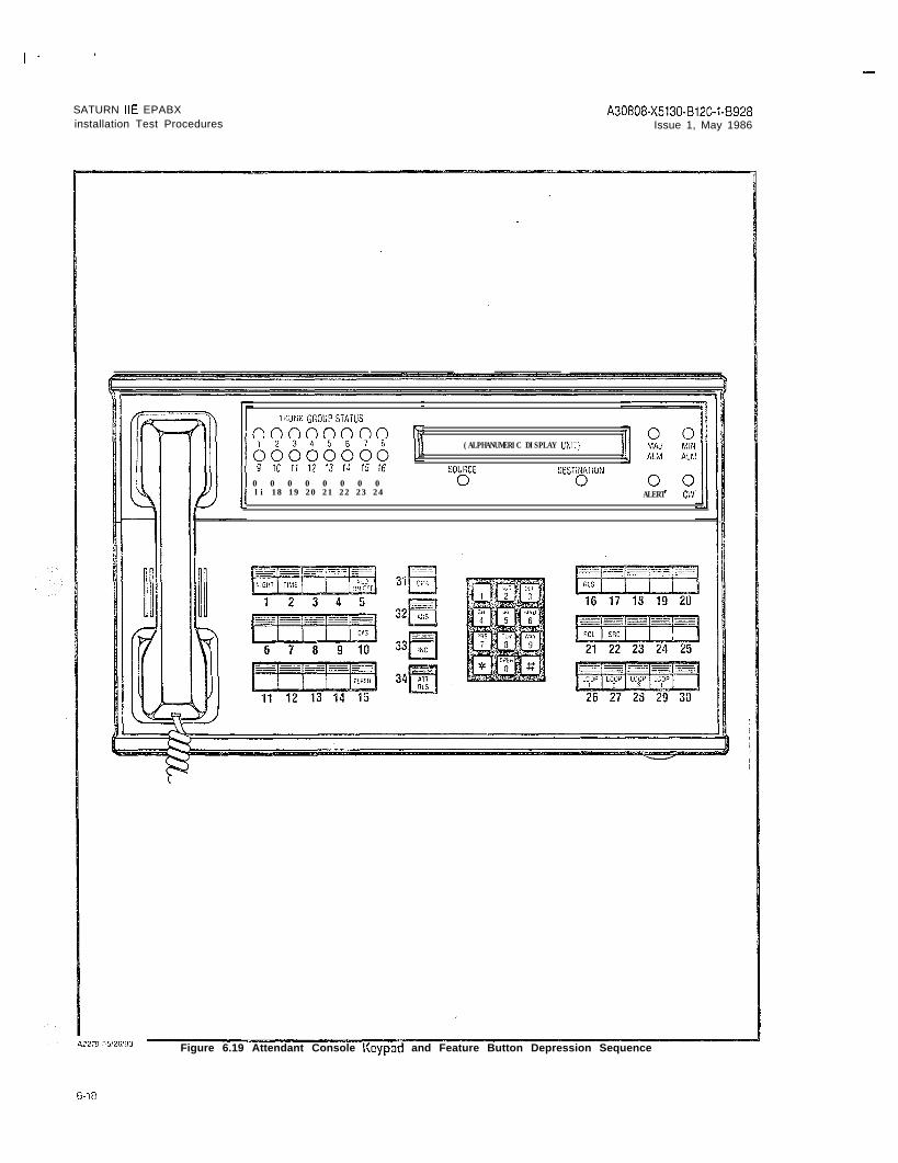
I -
SATURN IIE EPABX A30808-X5130-8120-143928installation Test Procedures Issue 1, May 1986
TRUNK GGOUPSTATUS
nnnnnnnn k(ALPHANUMERIC DISPLAY L'NI;)
SOUlxi OESTIXATION0 0 0 0 0 0 0 0li 18 19 20 21 22 23 24 ALERT CL'1
Figure 6.19 Attendant Console Keypad and Feature Button Depression Sequence

SATURN IIE EPABX A30808-X5130-B120-l-6926Installation Test Procedures Issue 1, May 1986
Table 6.06 Attendant Console Displayable Characters
ORDER
1 .2 .3 .4 .5 .6 .7 .8 .9 .
1 0 .1 1 .1 2 .1 3 .1 4 .1 5 .1 6 .1 7 .181 9 .2 0 .2’:.
2 3 :2 4 .2 5 .2 6 .2 7 .
2 8 .2 9 .3 0 .
3 1 .3 2 .
CHARACTER
I I I I I I ! !;;;;,A!,;;;;
$$$$5$$$o/o o/o 010 o/o o/o o/o o/o %&&&&&&&&I I I I I I I I
( ( ( ( ( ( ( () 1 1 1 1 1 1 1* l * * * l * *
++++++++I I > 9 I 1 3I- - - - - - - -
i i i i i i i i0 0 0 0 0 0 0 01 1 1 1 1 1 1 12 2 2 2 2 2 2 23 3 3 3 3 3 3 34 4 4 4 4 4 4 45 5 5 5 5 5 5 5 6 6 6 6 6 6 6 6
7 7 7 7 7 7 7 78 8 8 8 8 8 8 89 9 9 9 9 9 9 9: : : : : : : :; ; ; ; ; ; ; ;(((((((CTPffSf=>S
? ? ? ? ? ? ? ?OQOQ@@@@
ORDER CHARACTER
3 3 . A A A A A A A A3 4 . BBBBBBBB
c c c c c c c cii: D D D D D D D D
37. E E E E E E E EF F F F F F F F
:i G G G G G G G G4 0 : H H H H H H H H4 1 . I I I I I I I I
4 2 . J J J J J J J J4 3 . K K K K K K I< K4 4 . L L L L L L L L4 5 . MMMMMMMM4 6 . N N N N N N N N4 7 . 0 0 0 0 0 0 0 0
4 8 . P P P P P P P P4 9 . Q Q Q Q Q Q Q Q5 0 . RRRRRRRR5 1 . s s s s s s s s5 2 . T T T T T T T T5 4 . 5 3 . v vvvvvvv uuuuuuuu
5 5 . w w w w w w w w5 6 . x x x x x x x x2; YYYYYYYY
z z z z z z z z5 9 : [ I [ 1 I 1 1 I6 0 .61.
\\\\)))\1 1 I I
6 2 . A A A A ,I> A A A6 3 . ----_---
6 - 1 9

I .
SATURN IIE EPABX A30808-X5130-B120-I-6928Installation Test Procedures Issue 1, May 1986
Table 6.07 Siemcns Digital Telephone - DVAD Dutton Test
NOTES: 1) If the system option flag TSTDIAG has been enabled in the data base or the Siemcns Digital Telephone undertest is classmarked with TSTAPP feature, the maintenance test phone is nbt required to enable or disable theApparatus Diagnostic routines; therefore, perform only steps 5 through 9.
2) If the system option flag TSTDIAG has been disabled in the data base or the Siemens Digital Telephone undertest is not classmarked with the TSTAPP feature. the maintenance test phone is required to enable or disablethe Apparatus Diagnostic routine? s; t herefore, perform the entire procedure (steps 1’ through 10).
STEP
1
2
3
4
5
6
7
8
9
1 0
PROCEDURE . VERIFICATION
‘lace the maintenance test phone,ff-hook.
3ial the Diagnostic Test Access Code.
I ial 3 to enable the Apparatus Diag-lostic Tests.
‘lace ma in tenance tes t phonex+hook.
‘lace Siemens DYAD Telephone,ff-hook.
Dial the Siemens Digital Telephonerest Access Code.
Ieoress the Siemens DYAD Telc-&ne keypad buttons as, fo!lows: 1,3, 3 , 4 , 5 , 6, 7 , 8 , 9 , 0 , * , i?.
Depress the DYAD feature buttons inthe sequence shown in Figure 6.20and according to the Siemens DYADT e l e p h o n e m o d e l .
Place Siemens DYAD Telephone un- Siemens DYAD Telephone returns toder test on-hook to terminate test. normal operation.
If no additional Apparatus DiagnosticT e s t r o u t i n e s a r e t o b e p e r f o r m e d , p r o -ceed as follows:
Place maintenance test phoneoff-hook.
Dial tone is returned.
Dial the Diagnostic Test Access code. Recall dial tone is returned.
Dial 2 to disable the Apparatus Diag-nostic Test.
N o n e .
Place maintenance test phone on-hook.None.
N o n e .
I ial tone is returned.
qecall dial tone is returned.
>onfirmation tone is returned.
U o n e .
I ial tone is returned.
secall dial tone is returned.
The access code is momentarily dis- f reorder tone is returned, the Sie-3layed, then the display unit and but- nens DYAD Telephone Button Test iston LEDs are extinguished. n use, try later.
Button LEDs light when depressedand extinguish when the next buttonis depressed.
After the last button is depressed, thefollowing indications occur:
Ringback tone is returned.
All button LEDs flash.
T h e a u d i b l e a l e r t i n g d e v i c e s o u n d s a ti n t e r v a l s .
TEST COMPLETE is displayed.
IF VERiFICATlONIS NOT OBTAINED
f proper verification is not obtained crxsy tone is returned at eny time,either the keypad buttons cr featuiebuttons were depressed out of se-q u e n c e , t h e DYAD T e l e p h o n e i s defac-tive, or the SLMD circuit is defective.T o i s o l a t e t h e f a i l u r e , r e t r y t e s t t o v e r i -f y t h a t t h e b u t t o n s w e r e n o t d e p r e s s e dDut of sequence.
I f p r o p e r v e r i f i c a t i o n i s n o t o b t a i n e d o rbusy tone is returned again, replacethe Siemens DYAD Telephone undertest with a known good DYAD Tele-phone and retry test. If proper verifi-cation is not obtained or busy tone isreturned again, replace the SLMDPCB.
I -
6 - 2 0

I-
SATURN HE EPABXInstallation Test Procedures
A30808-X5130-8120-1-8928Issue 1, May 1986
IS BUTTOND Y A D
26 BUTTOND Y A D
S E E N O T E
NOTE: These buttons do notcontain LEDs.
SEE NOTE y
/ ’
I
Figure 6.20 Siemens DYAD Telephone Button Depression Sequence
6 - 2 1

SATURN IIE EPABXInstallation Test Procedures
A30808-X5130-BlZO-l-8928Issue 1, May 1986
Table 6.06 Siemcns Digital Telephone - JR-DYAD Button Test
NOTES: 1) If the system option flag TSTDIAG has been enabled in the data base or the Siemens Digital Telephone undertest is classmarked with TSTAPP feature, the maintenance test phone is ‘not required to enable or disable theApparatus Diagnostic routines; therefore, perform only steps‘5 through 9.
2) If the system option flag TSTDIAG has been disabled in the data base or the Siemens Digital Telephone undertest is not classmarked with the TSTAPP feature, the maintenance test phone is required to enab!e or disablethe Apparatus Diagnostic routines; therefore, perfcrm ihe entire procedure (steps 1 through i0).
STEP PROCEDURE VERIFICATION IF VERIFICATIONIS NOT OBTAINED
1 Place the maintenance test phone Dial tone is returned.off-hook.
2 D i a l t h e Diagncstic T e s t A c c e s s C o d e . Recall dial tone is returned.
3 Dial 3 to enable the Apparatus Diag- Confirmation tone is returned.nostic Tests,
4 P lace ma in tenance tes t phone None .on-hook.
5 Place JR-DYAD Telephone off-hook. Dial tone is rereturned.
6 Dial the Siemens Digital Telephone Recall dial tone is returned. If reorder tone is returned, the Sie-Test Access Code. m e n s J R - D Y A D Telephcne B u t t o n T e s t
is in use, try later.
7 Depress the Siemens JR-DYAD Tele- Ii proper verification is net obtainsd orphone keypad buttons as, follows: 1, busy tone is returned at any iime,2, 3, 4, 5, 6, 7, 8, 9, 0, * , #. either the keypad buttons or feature
buttons were depressed out of se-8 Depress the JR-DYAD feature buttons Button LEDs light when depressed quence, the JR-DYAD Telephone is
i n t h e s e q u e n c e s h o w n i n F i g u r e 6 . 2 1 . and extinguish when the next button defective, or the SLMD circuit isis depressed. defective. To isolate the failure, retry
test to verify that the buttons were notAfter the last button is depressed, the depressed out of sequence.following indications occur:
I f p r o p e r v e r i f i c a t i o n i s n o t o b t a i n e d o rRingbac!c tone is returned. busy tone is returned again, replace
All button LEDs flash.t h e S i e m e n s J R - D Y A D T e l e p h o n e u n -der test with a known good JR-DYAD
T h e a u d i b l e a l e r t i n g d e v i c e s o u n d s a tTelephone and retry test. If proper
intervals.verification is not obtained or busytone is returned again, the SLMD cir-cuit is defective and the SLMD PC6requires replacement.
9 Place Siemens JR-DYAD Telephone Siemens JR-DYAD Telephone returnsunder test on-hook to terminate test. to normal operation.
1 0 If no additional Apparatus DiagnosticT e s t r o u t i n e s a r e t o b e p e r f o r m e d , p r o -ceed as follows:
P&tokmaintenance test phone Dial tone is returned.
Dial the Diagnostic Test Access code. Recall dial tone is reiurned.
Dial 2 to disable the Apparatus Diag- N o n e .nostic Test.
P lace ma in tenance tes t phone None .on-hook.
6-22

I -
SATURN IIE EPABX A30808-X5130-B120-l-8928Installation Test Procedures Issue 1, May 1986
N O T E S :* These feature buttons are not testable.
Buttons 9 through 13 do not contain LEDs.
Figure 6.21 Siemeno JR-DYAD Telephone Button Depression Sequence
6-23

I . I-
SATURN IIE EPABXInstallation Test Procedures
A30808-X5130-B120-l-8928Issue 1, May 1986
Table 6.09 Siemens Digital Telephone -DYAD Display Test
NOTES: 1) If the system option flag TSTDIAG has been enabled in the data base or the Siemens Digital Telephone undertest is classmarked with TSTAPP feature, the maintenance test phone is not required to enable or disabie theApparatus Diagnostic routines; therefore, perform only steps 5 through 9.
2) If the system option flag TSTDIAG has been disabled in the data base or the Siemens Digital Telephone undertest is not classmarked with the TSTAPP feature, the maintenance test phone is required to enable or disablethe Apparatus Diagnostic routines; therefore, perform the entire procedure (steps 1 through 10).
XEP PROCEDURE VERIFICATION IF VERIFICATIONIS NOT OBTAINED
1 Place maintenance test phone Dial tone is returned.off-hook.
.
. / ;
2 D i a l t h e D i a g n o s t i c T e s t A c c e s s C o d e . Recall dial tone is returned.
3 Dial 3 to enable the Apparatus Diag- Confirmation tone is returned.nostic test.
4 P lace ma in tenance tes t phone None .on-hcok.
5 P l a c e t h e S i e m e n s D i g i t a l T e l e p h o n e Dial tone returned.under test off-hook.
G Dial the Siemens Digital Telephone Recall dial tone is returned. The Ac- If reorder tone is returned, the Sie-test access code. cess code is momentarily displayed, mens Digital Telephone Display Test
then the display unit clears. is being used, retry later.
7 Depress any button in the Siemens Groups of 16 of each of the displaya- If verification is not obtained, eitherD i g i t a l T e l e p h o n e u n d e r t e s t t o i n i t i a t e ble characters are scrolled in the se- t h e S i e m e n s D i g i t a l T e l e p h o n e o r t h etest. quence s h o w n i n T a b l e 6 . 0 9 . A f t e r t h e SLMD circuit is defective. Replace
last characier (underscore) is dis- Siemens Digital Telephone with a(Note: The display test can be sus- played the following occurs: good one and retry test. If verificationpended any time by depressing any is obtained, replace the Siemens Dig-button. The test can be resumed at Ringback tone is returned. ital T e l e p h o n e .any time in the same manner.)
All button LEDs flash and the audible If verification is still not obtained,alerting device sounds at intervals. replace the SLMD PCS.
TEST COMPLETE is displayed.
8 P l a c e S i e m e n s D i g i t a l T e l e p h o n e on-hook to terminate test or wait 30 se-conds for test timeout.
9 If no additional Apparatus DiagnosticT e s t s a r e t o b e p e r f o r m e d , p r o c e e d a sfollows:
Place maintenance test phone Dial tone returned.off-hook.
D i a l t h e D i a g n o s t i c T e s t A c c e s s C o d e . Recall dial tone is returnedRecall dial tone returned.
Dial 2 to disable the Apparatus Diag- N o n e .nostic Test.
P lace ma in tenance tes t phone None .on-hook.
G - 2 4

i . I
SATURN IIE EPABX A30808-X5130-B120-l-6928Installation Test Procedures Issue 1, May 1986
Table 6.10 Siemens Digital Telephone Displayable Characters
ORDER CHARACTER ORDER CHARACTER
1 . ! ! ! ! ! ! ! ! ! ! ! ! ! ! ! ! 3 3 . A A A A A A A A A A A A A A A A2 . #P It It I, I, ,I 0 0 I, r , 0 I, 0 I, ,I I, 34, B B B B B B B B B B B B B B B B3 . #H#H#####,Y###### 3 5 . c c c c c c c c c c c c c c c c4 . $ssssss$s$s$s$s$ 3 6 . D D D D D D D D D D D D D D D D5 . o/b 010 vo %%%% vo vo o/o %% o/o %% o/o 3 7 . E E E E E E E E E E E E E E E E6 . &&&&&&&&&&.&&&&&& 3 8 . F F F F F F F F F F F F F F F F7. 3 9 . G G G G G G G G G G G G G G G G8 . ;;;;;;;;;1;;;;;; 4 0 . H H H H H H H H H H H H H H H H9 . ))))))))))))))I) 4 1 . I I I I I I I I I I I I I I I I
1 0 . **************** 4 2 . J J J J J J J J J J J J J J J J1 1 . - I - + + + + + + + + + + + + + + + 4 3 . K K K K K K K K K K K K K K K K1 2 . 0000000e00.0.0.. 4 4 . L L L L L L L L L L L L L L L L1 3 . - - - - - - - - - - - - - - - 4 5 . M M M M M M M M M M M M M M M M1 4 . 4 6 . N N N N N N N N N N N N N N N N1 5 . GE;;;;;;;;;;; 4 7 . 0 0 0 0 0 0 0 0 0 0 0 0 0 0 0 01 6 . 0 0 0 0 0 0 0 0 0 0 0 0 0 0 0 0 4 8 . P P P P P P P P P P P P P P P P1 7 . 1 1 1 1 1 1 1 1 1 1 1 1 1 1 1 1 4 9 . QQQQQQQQQQQQQQQQ1 8 . 2 2 2 2 2 2 2 2 2 2 2 2 2 2 2 2 5 0 . RRRRRRRRRRRRRRRR1 9 . 3 3 3 3 3 3 3 3 3 3 3 3 3 3 3 3 5 1 . ssssssssssssssss
2 0 . 4 4 4 4 4 4 4 4 4 4 4 4 4 4 4 4 5 2 . T T T T T T T T T T T T T T T T2 1 . 5 5 5 5 5 5 5 5 5 5 5 5 5 5 5 5 5 3 . u u u u u u u u u u u u u u u u
2 2 . 6 6 6 6 6 6 6 6 6 6 6 6 6 6 6 6 5 4 . vuvvvvuvvvvvuvvv2 3 . 7 7 7 7 7 7 7 7 7 7 7 7 7 7 7 7 5 5 . w w w w w w w w w w w w w w w w2 4 . 8 8 8 8 8 8 8 8 8 8 8 8 8 8 8 8 5 6 . x x x x x x x x x x x x x x x x2 5 . 9 9 9 9 9 9 9 9 9 9 9 9 9 9 9 9 5 7 . YYYYYYYYYYYYYYYY2 6 . . . . * . . . . . . . . . . . .. . . . . . . . . . . . . . . . 5 8 . z z z z z z z z z z z z z z z z2 7 . . . . . . . . . . . . . . . . .2 8 . ~~~~t~~~~i~i~lii
5 9 . 11 1 [ I [ [ [ 11 I[ [ [ [ [G O .
2 9 .\ \ \ > \ \ \ \ \ \ \ \ \ \ :\ \ \
========zz==3 0 . ff~~~,,,,,,,,,,,
6 1 . 1 1 1 I I I 1 1 1 1 1 1 1 1 1 16 2 . AAAAAAAAAAAAAAAA
3 1 . ? ? ? ? ? ? ? ? ? ? ? ? ? ? ? ? 6 3 . - - - - - _ _ _3 2 . Q@Q@@@@@@@@Q@QOQ
6 - 2 5

SATURN IIE EPABX‘nstallation Test Procedures
Table 6.11 Outgoing Trunk Test
A30808-X5130-8120-l-8928Issue 1, May 1986
STEP
1
5
6
7
8 A
8 B
PROCEDURE VERlFiCATlCN
?lace ma in tenance tes t phoneo f f - h o o k .
D i a l t h e Diagnos?ic T e s t A c c e s s C o d e .
Dial 2 to enable trunk test.
Dial the two-digit trunk group number(00 through 31) coniaining the trunkcircuit to be tested.
Dial the two-digit trunk number (00 -99) of the trunk circuit to be tested.
For CO-type trunks (i.e., TMBM PCB),dial the test tone number provided bythe local phone company.
Verify that the returned test tone lev-el is correct, using a TMS.
If additional tests or procedures areto be performed, hook-flash the main-tenance test phone and dial the nextcode (Diagnostic Test Access Code isnot redialed).
I f n o a d d i t i o n a l t e s t s o r p r o c e d u r e s a r eto be performed, place the main-tenance test phone on-hook.
Iial tone is returned.
jecal l dial tone is returned.
done.
done.
20 or PABX dial tone is returned.41~0, the associated irunk circuit LEDIn the trunk PCB is lit steadily to in-licate the trunk has been seizedIutgoing.
Test tone (1004Hz) is returned
Recall dial tone is returned.
N o n e .
IF VERIFICATIONIS NOT OETAINED
I j
If reorder tone is returned, the select-ed trunk circuit is either an incoming-type, invalid, or not assigned (chec!cdata base assignments).
If busy tone is reiurned, the selectedtrunk is in use, retry later.
If CO or PABX dial tone is notreturned, verify trunk MDF cross-connections and attempt to accessCO/PABX trunk using a butt set. If thetrunlc is working properly replace thetrunk PCB under test and retry test.
If the reiurned test tone level is weak,replace PCB with another having thesame characteristics and retry test. Ifreturned test tone level increases con-siderably, trunk PCB is defective andshould be replaced. If the test tonelevel is still weak, contact CO repairservice to verify trunk facility.
i
i
6-26

-
SATURN IIE EPABX A30i308-X5130-B120-1-B928Installation Test Procedures Issue 1, May 1986 .
Table 6.12 Placing Circuit(s) In-Service
STEP PROCEDURE VERIF!CATION IF VERlFlCATIOflIS NOT OBTAiNED *
1 Place maintenance test phone Dial tone is returned.off-hook.
2 D i a l t h e D i a g n o s t i c T e s t A c c e s s C o d e . Recall dial tone is returned.
3 Dial 7 for placing a circuit in-service. N o n e .
4A If a single circuit is to be placed in- Coniirmation tone is returned. If reorder tone is returned, the seleci-service, dial the four digit PEN num- ed circuit is invalid or unassigned.bar of the circuit. Check data base assignments.
45 If all the circuits in a PCB are to be Confirmation tone is returned. If reorder tone is returned the select-placed in-service, dial the first three ed PCB is invalid or unassigneddigits of the PEN number for the PCB Check data base assignments,f o l l o w e d b y d i g i t 8 . F o r a n SLA16, d i a lthe first three digits of the PEN num-ber associated with the first eight cir-cuits followed by an 8, then dial thef i r s t t h r e e d i g i t s o f t h e a s s o c i a t e d P E Nnumber for the second eight circuits(W,X,Y+l) followed by an 8.
5 A If additional t&s or procedures are Recall dial tcne is returned.to be performed, hoolcilash the main-tenance test phcne and dial the nextcode (Diagnostic Test Access Code isnot redialed).
5B I f n o a d d i t i o n a l t e s t s o r p r o c e d u r e s a r e N o n e .to be performed, place the main-tenance test phone on-hook.
Table 6.73 Taking Ci:cuit(s) Out-et-Service
S T E P PROCEDURE VERIFICATION IF VERlFtCATIONIS NOT OBTAINED
1 Place maintenance test phone Dial tone is returned.off-hook.
2 D i a l t h e D i a g n o s t i c T e s t A c c e s s C o d e . Recall dial tone is returned.
3 Dial 8 for placing a circuit out-of- None.service.
4 A
48
If a single circuit is to be placed out- Confirmation tone is returned. If reorder tone is returned, the select-of-service, dial the four digit PEN ed circuit is invalid or unassigned.number of the circuit. Check data base assignments.
If all the circuits in a PCB are to be Confirmation tone is returned. If reorder tone is returned the select-placed out-of-service dial the first ed PCB is invalid or unassigned.t h r e e d i g i t s o f t h e P E N n u m b e r f o r t h e Check data base assignments.P C B f o l l o w e d b y d i g i t 8 . F o r a n SL416,dial the first three digits of the PENnumber associated with the first eightc i r c u i t s f o l l o w e d b y a n 8 , t h e n d i a l t h ef i r s t t h r e e d i g i t s o f t h e a s s o c i a t e d P E Nnumber for the second eight circuits(W,X,Y+l) followed by an 8.
6 - 2 7

I ’
SATURN IIE EPABXinstallation Test Procedures
Table 6.13 Takinq Circuit(s) Out-of-Service IContinucdl
A30808-X5130-8120-1-8928Issue 1, May 1986
. ,
STEP PROCEDURE VERIFICATION IF VERIFICATIONIS NOT OBTAINED
5A If additional tests or procedures are Recall dial tone is returned.to be performed, hook-flash the main-tenance test phone and dial the nextcode (Diagnostic Test Access Code isnot redialed).
5B If no additional tests or procedures are None.to be performed place the main-tenance test phone on-hook. . : j
6-28 (28 pages)

I.--
SATURN IIE EPABX A30808-X5130-B120-143928Installation Test Procedures Issue 1, May 1986
SECTKIN 7.00 INSTALLATION TEST PROCEDURES CHECKLlST
7 . 0 1 General. After performing the installation test proce-dures contained in this practice, each installation test proce-dure performed should be recorded to ensure that all tests
have been completed satisfactorily. Use Table 7.00, Installa-i ion Test. Procedures Checklist, for this purpose. This tablecan be used as a sign-off sheet, if required.
Table 7.00 Installation Test Procedures Checklist
7-l (7-2 bl!nnL,)