1 electric arc welding section 8 unit 25 & 26. 2 introduction a group of fusion welding...
TRANSCRIPT

1
Electric Arc Welding
Section 8Unit 25 & 26

2
Introduction
• A group of fusion welding processes that use an electric arc to produce the heat required for melting the metal.
• Advantages– Inexpensive power source
– Relatively inexpensive equipment
– Welders use standard domestic current.
– Portable equipment is available
– Process is fast and reliable
– Short learning curve
– Equipment can be used for multiple functions
• Electric arc is about 9,000 oF
Electric arc welding

3
Introduction-cont.
• All fusion welding process have thee requirements.– Heat
– Shielding
– Filler metal
• The method used to meet these three requirements is the primary difference between arc welding processes.

4
Arc Welding Requirements
Process Heat ShieldingFillerMaterial
SMAW
GMAW
ElectricArc
ElectricArc
Inert Gas(Flux)
Inert Gas(Cylinder)
StickElectrode
WireElectrode
In this class you will have the opportunity to use two (2) arc welding processes:
– SMAW
– GMAW

5
Eight Additional Electric Arc Welding Processes
1. FCAW
2. GTAW
3. SAW
4. ESW
5. EGW
6. PAW
7. ASW
Flux Core Arc Welding
Gas Tungsten Arc Welding
Submerged Arc Welding
Electroslag Welding
Electrogas Welding
Plasma Arc Welding
Arc Stud Welding
6
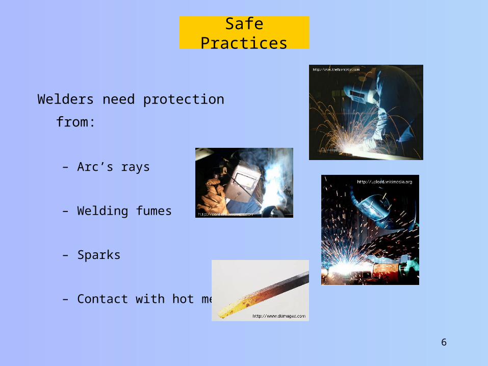
Safe Practices
Welders need protection from:
– Arc’s rays
– Welding fumes
– Sparks
– Contact with hot metal
7
Arc Welding Power Supplies
• The current for arc welder can be supplied by line current or by an alternator/generator.– The amount of heat is determined by the current flow (amps)
– The ease of starting and harshness of the arc is determined by the electrical potential (volts).
• Welding current adjustments can include: – Amperage– Voltage– Polarity– High frequency current– Wave form

8
Arc Welding Power Supplies--cont.
The type of current and the polarity of the welding current are one of the differences between arc welding processes.
– SMAW Constant current (CC), AC, DC+ or DC-
– GMAW Constant voltage (CV) DC+ or DC-
– GTAW Constant Current (CC) ), AC, DC+ or DC-

9
Twelve (12) Considerations When Selecting An Arc Welding Power Supply
1. Maximum Amperage
2. Duty cycle
3. Amperage range
4. Amperage adjustment
mechanism
5. Input power requirements
6. Initial cost and operating cost
7. Size and portability
8. Future needs for a power
supply
9. Available skills
10. Safety
11. Manufacturer's support
12. Open circuit voltage

10
1: Amperage Output
• The maximum output of the power supply determines the thickness of metal that can be welded before joint beveling is required.
• 185 to 225 amps is a common size.• For an individual weld, the optimum
output amperage is determined by the thickness of the metal, the type of joint, welding position and type of electrode.

2: Duty cycle
• The amount of continuous welding time a power supply can be used is determined by the duty cycle of the power supply.
• Duty cycle may be 100%, but usually is less.– Duty cycle is based on a 10 minute
interval.– Many power supplies have a
sloping duty cycle.
• Note in the picture there is a circle around the 75 amp setting. Why is it there?
11
What is the most likely outcome of exceeding a power supply duty cycle?

12
Five Common Output Currents For Arc Welding
1. AC (Alternating Current)
2. DC (Direct Current)
3. ACHF (Alternating Current-High Frequency)
4. PC (Pulsed Current)
5. Square wave
13
Arc Welding Electrical Terms
1. Electrical Circuit
2. Direct current (DC)
3. Alternating current (AC)
4. Ampere
5. Volt
6. Resistance
7. Ohms Law
8. Constant potential
9. Constant current
10. Voltage drop
11. Open circuit voltage
12. Arc voltage
13. Polarity
To understand how an electric arc welder works, you must understand the following thirteen (13) electrical terms.
14
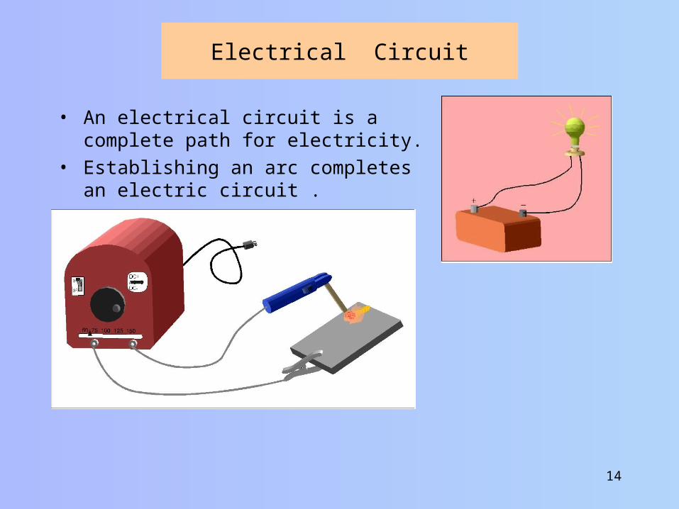
Electrical Circuit
• An electrical circuit is a complete path for electricity.
• Establishing an arc completes an electric circuit .

15
Alternating Current
• Alternating current: The type
of current where the flow of
electrons reverses direction
(polarity) at regular intervals.
• Recommended current for
SMAW general purpose
electrodes and flat position.

16
Direct Current
• Direct current: The type
of current where the flow
of electrons (polarity) is in
one direction.
• Controlling the polarity
allows the welder to
influence the location of
the heat.
• When the electrode is
positive (+) DCRP or
DCEP it will be slightly
hotter than the base
metal.
• When the base metal is positive (+),
DCSP or DCEN, the base metal will be
slightly hotter than the electrode.
• DC current is required for GMAW
• It is frequently used for SMAW

17
Ampere
• Amperes: the unit of measure for current flow.• One ampere is equal to 6.24150948×10¹⁸
electrons passing by a point per second.• Electricity passing through a resistance causes
heat.• An air gap is a high resistance
• The greater the amperage flowing through the resistance (air gap)--the greater the heat.
• The electrode also has resistance.• Excessive amperage for the diameter of the electrode (current
density) over heats the electrode. • Insufficient amperage for the diameter of electrode makes the
electrode hard to start.
What are the characteristics of an electrode that was used with excessive current density?

18
Voltage
• Voltage is the measure of electromotive
force (Emf).
• Emf is measured in units of volts
• The voltage at the electrode for SMAW
determines the ease of starting and the
harshness of the arc.
– Higher voltage = easier starting.
– Starting voltage is called OCV.
• Voltage is adjustable in dual control SMAW machines.
• Changing the voltage adjusts a GMAW machine for different
metal thickness.

19
Resistance
• Def: that characteristic of a material that impedes the flow of an electrical current.
• Measured in units of Ohm’s ( )• When an electrical current passes through a resistance heat
(BTU) is produced.• The amount of heat produced is a function of the amount of
resistance (Ohm’s) and the amount of current (amps).
Is the resistance adjustable in the SMAW process?

20
Ohm’s Law
• Ohm's law states that, in an electrical circuit, the current passing through a material is directly proportional to the potential difference.
• Commonly expressed as:
€
I =E
R
€
E = I R
• Ohm’s law also be used to teach a principle of electrical safety. Amperage is the harmful portion of
electrical current. Rearranging Ohm’s Law for
amperage shows that amperage (current flow) is determined by the voltage divided by the resistance.
The higher the resistance, the less current that will flow for a given voltage.
What does this principle mean for SMAW?
21
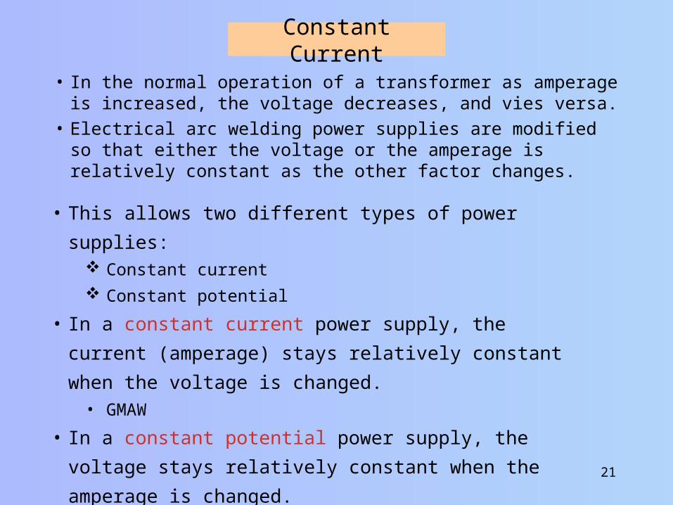
Constant Current
• In the normal operation of a transformer as amperage is increased, the voltage decreases, and vies versa.
• Electrical arc welding power supplies are modified so that either the voltage or the amperage is relatively constant as the other factor changes.
• This allows two different types of power supplies: Constant current
Constant potential
• In a constant current power supply, the current (amperage)
stays relatively constant when the voltage is changed.• GMAW
• In a constant potential power supply, the voltage stays
relatively constant when the amperage is changed.• SMAW

22
Constant Current--cont.
• Characteristics of constant current power supply.• The machine provides a high voltage for striking the arc.
• Open circuit voltage (OCV)
• OCV is not adjustable for most machines
• When the arc is struck the voltage drops to the welding voltage.• Arc voltage
• Arc voltage varies with the arc length.
• As the welding proceeds the current will not vary much as the
arc length changes.

23
Constant Current-cont.
• Increasing the voltage from 20 to 25 volts (25%) only decreases the amperage from 113 to 120 Amp (5.8%).

24
Constant Potential
• The constant potential power supply is modified to produce a relatively constant voltage as the amperage changes.
0
10
20
30
40
50
60
70
80
0 50 100 150 200 250
Anperes
Volts
• Characteristic of GMAW power supplies.

25
Voltage Drop
• Voltage drop is the reduction in voltage in an electrical circuit
between the source and the load.
• Primary cause is resistance.
• When an excessive voltage drop exists, the electrical circuit will
not perform as designed.
– Localized resistance (connection) can cause excessive heat.
– Excessive heat can cause component failure.
• When extra long welding leads are used, the amperage must be
increased to have the same heat at the weld.

26
Joints, Welds & Positions
Butt
Lap
T
Corner
Edge
Electric arc welding uses the same five (5) types of joints and five (5) types of welds and five (5) positions.
Five (5) joints:

27
Joints, Welds & Positions Five types of welds
1. Surface
2. Groove
3. Fillet
4. Plug
5. Slot

28
1. Surface Welds
• Surface welds are welds were a material has been applied to the surface of another material.
May or may not be blended with the work piece.
• Two common applications are for hard surfacing and padding.

29
2. Groove Welds
Groove welds are used to fuse the sides or ends of two pieces of metal.
The primary use of groove welds is to complete butt joints.

30
3. Fillet Welds
Fillet welds have a triangular cross section and are used to fuse two faces of metal that are at a 90 degree angle to each other.
Lap JointOutside Corner T Joint

31
4. Plug Welds
Plug welds are used to attach two surfaces together when a complete joint is not required and the design does not allow for any weld bead outside the dimensions of the metal.
The holes can be made with a drill bit or punch.
The weld is completed by establishing the arc on the bottom plate and then continuing to weld until the hole is full.

32
5. Slot Welds
Slot welds are identical to plug welds except for the shape of the holes. For slot welds, slots are machined or stamped in the upper plate.
They are complete the same as plug welds.

33
Joints, Welds & Positions Arc Welding Positions
HorizontalFlat
Vertical Up
Overhead
Vertical Down

34
Weld Nomenclature
PenetrationBead
Base metal
Joint Angle Reinforcement
Bead
Root FaceExcessive Penetration
Root Opening
35
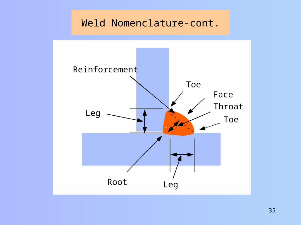
Weld Nomenclature-cont.
Root
Throat
FaceToe
Reinforcement
Leg
Leg
Toe

36
Weld Nomenclature-cont.
• In multiple pass welds, each pass has a specific function.
Tack Weld
Root PassFiller Pass
Cover Pass
• A tack weld is used to hold the joint at the desired gap.
– If it is not used, the heat of the weld will cause the joint to close.
• The filler pass is used to fill in the joint.– A pattern bead or multiple stringer beads will be used.
• The root pass is used to fuse the root of the weld.
– If the root pass does not have adequate penetration, it must be cut or gouged out before the weld is completed.
• The cover pass isn’t used for strength. It is used for appearance and to fill in surface voids.

37
Bead Patterns
• Pattern beads are used whenever a wider bead is needed.– Hardsurfacing
– Filler pass
– Cover pass
– Reduce penetration
• Common patterns:– Circle
– Crescent
– Figure 8

38
Weld Defects
• A weld defect is any physical characteristic in the completed weld that reduces the strength and/or affects the appearance of the weld.
• The mark of a good welder is the ability to identify weld defects and adjust the welding parameters to eliminate them.
• Defects that are not visible must be detect by using destructive or nondestructive testing.
• If the defects in a weld exceed the specifications, the weld must be removed and redone.
• Welds are removed by grinding, gouging and cutting.• Eliminating a weld defect is time consuming and expensive --
you must be able to complete the weld correctly the first time.

39
Common Defects and Causes
The depth of the weld is less than specifications.
Excessive heat
Excessive speed.
The weld metal is not completely fused to base metal or passes are not completely fused.
Description Cause(s)
Incorrect angle
Incorrect manipulation
Insufficient heat
Weld material flows over, but is not fused with the base metal.
Slow speed

40
Common Defects and Causes--cont.
Weld bead does not extend to the desired depth.
Description Cause(s)
Low heat
Long arc
Incorrect joint design
Small indentions in the surface of the weld
Excessive gas in the weld zone.
Moisture
Rust
Dirt
Accelerated cooling
Small voids throughout the weld material.

41
Usually visible cracks on the surface or through the weld
Common Defects and Causes--cont.
Description Cause(s)
Accelerated cooling
Constrained joint
Small weld volume
Cracks in the transition zone between the weld and base metal
Induced hydrogen
Incompatible electrode or wire
Accelerated cooling
Misshapen and/or uneven ripples
Inconstant speed
Incorrect manipulation
Incorrect welder settings

42